JP4121069B2 - Circular cutting method in pavement construction - Google Patents
Circular cutting method in pavement construction Download PDFInfo
- Publication number
- JP4121069B2 JP4121069B2 JP2002233078A JP2002233078A JP4121069B2 JP 4121069 B2 JP4121069 B2 JP 4121069B2 JP 2002233078 A JP2002233078 A JP 2002233078A JP 2002233078 A JP2002233078 A JP 2002233078A JP 4121069 B2 JP4121069 B2 JP 4121069B2
- Authority
- JP
- Japan
- Prior art keywords
- pavement
- lid
- cutting
- manhole
- temporary
- Prior art date
- Legal status (The legal status is an assumption and is not a legal conclusion. Google has not performed a legal analysis and makes no representation as to the accuracy of the status listed.)
- Expired - Lifetime
Links
- 238000005520 cutting process Methods 0.000 title claims description 102
- 238000000034 method Methods 0.000 title claims description 40
- 238000010276 construction Methods 0.000 title claims description 21
- 238000012790 confirmation Methods 0.000 claims description 44
- 238000009434 installation Methods 0.000 claims description 18
- 239000000463 material Substances 0.000 claims description 17
- 238000005553 drilling Methods 0.000 claims description 13
- 238000011900 installation process Methods 0.000 claims description 13
- 238000005429 filling process Methods 0.000 claims description 7
- 230000000149 penetrating effect Effects 0.000 claims description 4
- 239000002344 surface layer Substances 0.000 claims description 3
- 239000010426 asphalt Substances 0.000 description 4
- 238000010586 diagram Methods 0.000 description 4
- 238000005096 rolling process Methods 0.000 description 4
- 230000000694 effects Effects 0.000 description 3
- 238000010438 heat treatment Methods 0.000 description 3
- 239000004570 mortar (masonry) Substances 0.000 description 2
- 229920005989 resin Polymers 0.000 description 2
- 239000011347 resin Substances 0.000 description 2
- 239000000758 substrate Substances 0.000 description 2
- 208000019901 Anxiety disease Diseases 0.000 description 1
- 229910001018 Cast iron Inorganic materials 0.000 description 1
- 230000036506 anxiety Effects 0.000 description 1
- 239000003795 chemical substances by application Substances 0.000 description 1
- 238000004140 cleaning Methods 0.000 description 1
- 238000005056 compaction Methods 0.000 description 1
- 239000010410 layer Substances 0.000 description 1
- 238000005259 measurement Methods 0.000 description 1
- 239000002184 metal Substances 0.000 description 1
- 229910052751 metal Inorganic materials 0.000 description 1
- 239000003973 paint Substances 0.000 description 1
- 230000002093 peripheral effect Effects 0.000 description 1
- 229920003002 synthetic resin Polymers 0.000 description 1
- 239000000057 synthetic resin Substances 0.000 description 1
Images


Landscapes
- Road Paving Structures (AREA)
- Road Repair (AREA)
Description
【0001】
【発明の属する技術分野】
本発明は、マンホールを含む道路における舗装の新設や既設舗装の打換等の舗装工事に際して実施される円形切断方法に関する。
【0002】
【従来の技術】
マンホールが設置してある道路の舗装は、舗装に埋設してある鋳鉄製のマンホール蓋受枠が舗装工事の連続性を分断するので施工能率を下げ、ロードローラなどの転圧機械ではマンホール直近を転圧することができず、手持ちの転圧機で転圧せざるをえず、転圧不足が生じていた。また、舗装を施工する前にマンホール蓋受枠を設置するため、道路の縦断勾配及び横断勾配にマンホール蓋受枠を合わせるのが難しく、段差が生ずる場合があった。
【0003】
そこで、特許第2623490号等に示されるように、マンホール受枠設置に先行してマンホール部分を含めて舗装をおこない、その後にマンホール蓋受枠を設置するという工法が開発された。
【0004】
これらの工法は、図5に示すように、斜壁11を有するマンホール1の開口を仮蓋3等で塞ぎ、開口上を他の道路部分と同様に連続的に舗装2し、舗装完了後にマンホール開口位置の舗装2aを開口の形状に合わせて撤去してマンホール斜壁11上部を露出させ、マンホール蓋受枠10を路面の縦断勾配及び横断勾配に合致するように設置するものである。つまり、舗装工事の完了後にマンホール蓋受枠10を路面に合わせて設置するものであり、従来の工法とはマンホールの蓋受枠の設置手順が逆になっている。したがって、路面にマンホールが存在しないかのように舗装を連続的に施工でき、施工の効率化、及び、マンホール周辺の転圧不足を解消できたのである。
【0005】
この工法において、オーバーレイ舗装や新設舗装のマンホール上部の舗装の撤去においては、ブレーカによる破砕、円形カッターでマンホール周囲を四角形に切断したり、実用新案登録第3010469号公報に開示されるように、油圧ジャッキによってマンホール蓋受枠と舗装を一体的に剥ぎ取ったり、あるいは、特公昭61−25844号公報や特公昭61−33938号公報に開示されるように、円筒型切断機でマンホール周囲を円形に切断することができる。
また、舗装がアスファルト舗装の場合は、加熱によってアスファルト舗装を軟化させて撤去する工法も提案されている。
【0006】
【発明が解決しようとする課題】
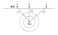
この工法においては、マンホール上は周辺と同様に一様に舗装されるため、舗装完了後はマンホールの位置が目視では確認できなくなる。マンホールの位置を正確に割り出すために、図3に示すように、道路側縁の3箇所の基点(A〜C)からマンホール中心までの距離(L1、L2、L3)を予め計測しておき、舗装完了後に3基点からの距離によって中心位置を割り出して舗装面にマークし、切断や加熱、または剥ぎ取りなどの種々の手段によってマンホール部分の舗装を撤去してマンホールを露出させていた。
【0007】
中心の割り出しには、理論的には3点からの測量を正確におこなえばマンホール中心位置を間違えることはないのであるが、基点の移動などの予測できない事故の発生、また、マンホールが道路中央にあって道路側縁からの距離が長いと、計測誤差が生ずることもあり、舗装を撤去して確認するまで、施工者には中心位置を間違えていないかという不安がつきまとっていた。
本発明は、そのような不安を払拭するため、マンホールの中心位置を確認してから次の工程にはいることができるようにすることである。
【0008】
【課題を解決するための手段】
舗装新設工事は、路面に設置されたマンホールの開口を仮蓋3により閉塞する仮蓋設置工程と、前記仮蓋3の上方を含めて路面を舗装する舗装工程と、切断機でマンホール周囲の舗装4を路面から円形に切断する切断工程と、前記切断された切断舗装部と仮蓋3を撤去する撤去工程と、蓋受枠10を舗装表面と合致するようにマンホールに設置する蓋受枠設置工程と、前記蓋受枠10の周囲に舗装補修材41を充填して周囲の舗装4と一体化する充填工程とから成るところ、本発明が上記課題の解決手段とする技術的構成は次の通りである。
【0009】
即ち、舗装新設工事に関して本発明が第一の手段として構成したところは、前記仮蓋設置工程に際して、仮蓋3は中心位置に中心目印Mを設けており、前記舗装工程の後で前記切断工程の前に、前記仮蓋3の中心部の上方で舗装4を表面から仮蓋3まで穿孔することにより確認孔Eを形成し、該確認孔Eを介して仮蓋3の中心目印Mを確認し、前記切断工程に際して、シャフト支持穴52aを有する中心固定装置5を舗装4の路面に設置し、該シャフト支持穴52aを前記確認孔Eに合致させた状態で、切断機の中心シャフトSを前記シャフト支持穴52aにセットしてマンホール周囲の舗装を円形に切断する点にある。
【0010】
また、舗装新設工事に関して本発明が第二の手段として構成したところは、前記仮蓋設置工程に際して、仮蓋3は中心位置に中心目印Mを設けており、前記舗装工程の後で前記切断工程の前に、前記仮蓋3の中心部の上方で舗装4を表面から仮蓋3まで穿孔することにより確認孔Eを形成し、該確認孔Eを介して仮蓋3の中心目印Mを確認し、前記切断工程に際して、上部開口に向けてテーパ状に広がるシャフト支持穴52aと該シャフト支持穴52aの中心部に連通して底部を貫通する底部穴52bを備えた中心固定装置5を舗装4の路面に設置し、前記底部穴52bと前記確認孔Eを介して仮蓋3の中心目印Mを再確認した後、切断機の中心シャフトSを前記シャフト支持穴52aにセットしてマンホール周囲の舗装を円形に切断する点にある。
【0011】
舗装打換工事は、道路に設置された既存のマンホールの蓋受枠と舗装を撤去する既存物撤去工程と、マンホールの開口を仮蓋3により閉塞する仮蓋設置工程と、前記仮蓋3の上方を含めて路面を舗装する舗装工程と、切断機でマンホール周囲の舗装4を路面から円形に切断する切断工程と、前記切断された切断舗装部と仮蓋3を撤去する撤去工程と、蓋受枠10を舗装表面と合致するようにマンホールに設置する蓋受枠設置工程と、前記蓋受枠10の周囲に舗装補修材41を充填して周囲の舗装4と一体化する充填工程とから成るところ、本発明が上記課題の解決手段とする技術的構成は次の通りである。
【0012】
即ち、舗装打換工事に関して本発明が第一の手段として構成したところは、前記仮蓋設置工程に際して、仮蓋3は中心位置に中心目印Mを設けており、前記舗装工程の後で前記切断工程の前に、前記仮蓋3の中心部の上方で舗装4を表面から仮蓋3まで穿孔することにより確認孔Eを形成し、該確認孔Eを介して仮蓋3の中心目印Mを確認し、前記切断工程に際して、シャフト支持穴52aを有する中心固定装置5を舗装4の路面に設置し、該シャフト支持穴52aを前記確認孔Eに合致させた状態で、切断機の中心シャフトSを前記シャフト支持穴52aにセットしてマンホール周囲の舗装を円形に切断する点にある。
【0013】
また、舗装打換工事に関して本発明が第二の手段として構成したところは、前記仮蓋設置工程に際して、仮蓋3は中心位置に中心目印Mを設けており、前記舗装工程の後で前記切断工程の前に、前記仮蓋3の中心部の上方で舗装4を表面から仮蓋3まで穿孔することにより確認孔Eを形成し、該確認孔Eを介して仮蓋3の中心目印Mを確認し、前記切断工程に際して、上部開口に向けてテーパ状に広がるシャフト支持穴52aと該シャフト支持穴52aの中心部に連通して底部を貫通する底部穴52bを備えた中心固定装置5を舗装4の路面に設置し、前記底部穴52bと前記確認孔Eを介して仮蓋3の中心目印Mを再確認した後、切断機の中心シャフトSを前記シャフト支持穴52aにセットしてマンホール周囲の舗装を円形に切断する点にある。
【0014】
切削オーバーレイ工事は、道路に設置された既存のマンホールの周囲の舗装を切断して蓋受枠を撤去する既存物撤去工程と、マンホールの開口を仮蓋3により閉塞する仮蓋設置工程と、前記仮蓋3の上方を仮舗装して既存の舗装40と同一レベルにする仮舗装工程と、既存の舗装40の表層と前記仮舗装の表面を切削する切削工程と、前記切削面の上にオーバーレイ43を舗装するオーバーレイ工程と、切断機でマンホール周囲のオーバーレイ43及び舗装40を路面から円形に切断する切断工程と、前記切断された切断舗装部と仮蓋3を撤去する撤去工程と、蓋受枠10をオーバーレイ43の表面と合致するようにマンホールに設置する蓋受枠設置工程と、前記蓋受枠10の周囲に舗装補修材41を充填して周囲の舗装と一体化する充填工程とから成るところ、本発明が上記課題の解決手段とする技術的構成は次の通りである。
【0015】
即ち、切削オーバーレイ工事に関して本発明が第一の手段として構成したところは、前記仮蓋設置工程に際して、仮蓋3は中心位置に中心目印Mを設けており、前記オーバーレイ工程の後で前記切断工程の前に、前記仮蓋3の中心部の上方でオーバーレイ43及び舗装40を表面から仮蓋3まで穿孔することにより確認孔Eを形成し、該確認孔Eを介して仮蓋3の中心目印Mを確認し、前記切断工程に際して、シャフト支持穴52aを有する中心固定装置5を舗装4の路面に設置し、該シャフト支持穴52aを前記確認孔Eに合致させた状態で、切断機の中心シャフトSを前記シャフト支持穴52aにセットしてマンホール周囲のオーバーレイ43及び舗装40を円形に切断する点にある。
【0016】
また、切削オーバーレイ工事に関して本発明が第二の手段として構成したところは、前記仮蓋設置工程に際して、仮蓋3は中心位置に中心目印Mを設けており、前記オーバーレイ工程の後で前記切断工程の前に、前記仮蓋3の中心部の上方でオーバーレイ43及び舗装40を表面から仮蓋3まで穿孔することにより確認孔Eを形成し、該確認孔Eを介して仮蓋3の中心目印Mを確認し、前記切断工程に際して、上部開口に向けてテーパ状に広がるシャフト支持穴52aと該シャフト支持穴52aの中心部に連通して底部を貫通する底部穴52bを備えた中心固定装置5を舗装4の路面に設置し、前記底部穴52bと前記確認孔Eを介して仮蓋3の中心目印Mを再確認した後、切断機の中心シャフトSを前記シャフト支持穴52aにセットしてマンホール周囲のオーバーレイ43及び舗装40を円形に切断する点にある。
【0017】
【実施例】
<舗装新設工事>
図1(a)に示すように、マンホール1が設置された道路の舗装にあたり、マンホール斜壁11の開口に仮蓋3を設置してマンホール開口を閉塞する。仮蓋3は、下面にズレ止めの突起31を有しており、中心部には穴30が設けてある。この穴30をテープ等で塞ぎ、仮蓋3の上に舗設される舗装材がマンホール内に落下しないようにすると共に、仮蓋3の中心位置を確認するための目印Mとする。新設舗装の場合、マンホール斜壁11の上端にマンホール蓋受枠が設置されていない状態なので、仮蓋3の上を含めて舗装路面全域を通常の方法で基層及び表層を舗装する。仮蓋3の上に施工された新設の舗装4は、マンホール蓋受枠10を設置する際に除去されるものなので、仮蓋3の表面に舗装材が付着して除去に手間取らないように仮蓋3の上面に剥離剤を塗布したり、剥離紙を貼り付けておき、清掃を容易にして仮蓋3を再使用しやすくする。または、耐熱性を有し、アスファルトの付着がしにくい材質のものを仮蓋とし、使用後、加熱して付着したアスファルトを除去する。
【0018】
図1(b)に示すように新設舗装工事をおこなうと、仮蓋3上も他の部分と同様に一様に舗装されるのでマンホールの位置が舗装4で覆われて判らなくなるので、図3に示すように、道路側端の複数の基点(A,B,C)からマンホール中心までの距離(L1,L2,L3)を測定して記録し、舗装完了後に基点からマンホール中心の位置出しをおこない、舗装面にペイントやチョークなどで中心位置及びマンホール開口の形状をマークとして描く。
新設舗装完了後、舗装面に描かれた中心マークの位置をφ100mmのコアドリルで舗装4を仮蓋3まで切断撤去することにより確認孔Eを穿孔し、該確認孔Eを介して仮蓋3の中心目印Mを視認することにより、マンホールの中心位置であることを確認する。中心目印Mが確認できない場合は、測量ミス等の原因で中心位置を外した可能性があるので、金属探知器などで仮蓋3の周縁位置を複数箇所で確認して中心位置を求める。
【0019】
中心位置を確認したところで、中心固定装置5をコアを抜いた路面に設置する。中心固定装置5は、図4に示すように、基板51の中央に上部開口に向けてテーパ状に広がるシャフト支持穴52aを備え、該シャフト支持穴52aの中心部に連通して底部を貫通する底部穴52bを備えている。
そこで、中心固定装置5の底部穴52bを通してマンホールの中心であることを再確認し、円筒型切断機(図示せず)の中心シャフトSを中心固定装置5のシャフト支持穴52aにセットし、マンホール周囲の舗装4を円形に切断して図1(c)のように舗装を撤去し、マンホールを露出させる。
【0020】
図1(d)に示すように、マンホール斜壁11上にマンホール蓋受枠10の高さを調整するコンクリート製または合成樹脂製の調整リング12を設置し、さらに調整モルタルで微調整してマンホール蓋受枠10を舗装4の表面の縦断勾配及び横断勾配に合致させて設置する。
【0021】
マンホール蓋受枠10の周囲にレジンコンクリート等の舗装補修材41を打設充填し、円弧状の転圧板を有する転圧機で転圧し、周辺の舗装4と一体になるようにする。必要に応じて打設充填した舗装補修材41を加熱養生する。
【0022】
<舗装打換工事>
舗装打換工事においては、マンホール蓋受枠を適宜の方法で撤去して既存の舗装を撤去し、マンホール開口を仮蓋3で閉塞する。その後の手順は上述した舗装新設工事と同様である。
【0023】
<切削オーバーレイ工事>
図2(a)に示すように、道路に設置されているマンホールの蓋を外し、マンホール周囲の舗装40を切断してマンホール蓋受枠を撤去する。マンホール蓋受枠がボルトでマンホール斜壁11に固定されていない場合には、マンホール蓋受枠を実用新案登録第3010469号に示されるようなマンホール蓋受枠剥ぎ取り装置で周囲の舗装と共にマンホール蓋受枠を撤去する。
マンホールの開口を仮蓋3で塞ぎ、その上に砕石を投入し仮舗装40aして既存の舗装40と同一レベルにする。既存の舗装40の表層及びマンホール上の仮舗装40aの表面を切削除去し、切削面43aを形成する。
【0024】
図2(b)に示すように前記切削面43aの上にオーバーレイ43を舗装する。マンホールがオーバーレイ43で覆われてしまい、位置が判らなくなるので、図3に基づいて上述した方法と同様の方法で、道路側端の複数の基点からマンホール中心までの距離を計測しておき、オーバーレイ舗装完了後にマンホールの位置をオーバーレイ43表面にマークを描いておく。ここで一旦交通開放することが可能である。
【0025】
図2(b)に示すように、舗装新設工事と同様に、マークの位置でオーバーレイ43及び舗装40をコアドリルにより表面から仮蓋3まで穿孔し撤去することにより確認孔Eを穿孔し、該確認孔Eを介して仮蓋3の中心目印Mを視認することによりマンホール中心位置を確認し、中心固定装置5を設置する。その際、舗装新設工事と同様に、中心固定装置5の底部穴52bを通してマンホールの中心であることを再確認し、円筒型切断機(図示せず)の中心シャフトSを中心固定装置5のシャフト支持穴52aにセットし、マンホール周囲のオーバーレイ43及び舗装40を円形に切断すると共に撤去し、図2(c)のマンホールを露出させる。
その後、マンホール斜壁11上にマンホール蓋受枠の高さを調整する調整リング12を設置し、さらに調整モルタルで微調整してマンホール蓋受枠10をオーバーレイ43の表面と同一レベルになるように設置する。
【0026】
図2(d)に示すように、マンホール蓋受枠10周囲にレジンコンクリート等の補修材41を打設充填し、円弧状の転圧板を有する転圧機で転圧し、周辺の舗装と一体になるようにする。
【0027】
【発明の効果】
請求項1、3又は5に記載の本発明の円形切断方法によれば、舗装の表面から仮蓋3まで確認孔Eを穿孔し、該確認孔Eを介して仮蓋3の中心目印Mを視認することにより、該確認孔Eが舗装で覆われたマンホールの中心位置にあることを目視で確認するので、中心位置にあると確認された確認孔Eに中心固定装置5を設置し、該中心固定装置5のシャフト用穴52aに切断機の中心シャフトSをセットすることにより、舗装で覆われたマンホールの中心に円形切断の中心を合致させた状態で、安心してマンホール蓋受枠設置工事における舗装撤去のための正確な円形切断をおこなうことができ、やり直しのリスクがないという効果がある。
【0028】
そして、請求項2、4又は6に記載の本発明の円形切断方法によれば、中心固定装置5は、基板51の中央に上部開口に向けてテーパ状に広がるシャフト支持穴52aを備えると共に、該シャフト支持穴52aの中心部に連通して底部を貫通する底部穴52bを備えているので、該底部穴52bと確認孔Eを介して仮蓋3の中心目印Mを確認することにより、該中心固定装置5の設置位置が舗装で覆われたマンホールの中心位置であることを再確認した上で、円形切断を行うことができるという効果がある。
【0029】
【図面の簡単な説明】
【図1】本発明の円形切断方法を用いた舗装新設工事の工程説明図である。
【図2】本発明の円形切断方法を用いた切削オーバーレイ工事の工程説明図である。
【図3】マンホール中心の求め方の説明図である。
【図4】本発明方法に使用する中心固定装置の斜視図と側面図である。
【図5】従来の舗装方法工程説明図である。
【0030】
【符号の説明】
M 中心目印
E 確認孔
1 マンホール
3 仮蓋
4 新設舗装
5 中心固定装置
10 マンホール蓋の受枠
11 斜壁
12 調整リング
40 既存舗装
41 補修材
43 オーバーレイ
52a シャフト用穴
52b 底部穴[0001]
BACKGROUND OF THE INVENTION
The present invention relates to a circular cutting method that is performed at the time of pavement work such as newly installing a pavement on a road including a manhole or replacing an existing pavement.
[0002]
[Prior art]
The pavement of roads where manholes are installed reduces the work efficiency because the cast iron manhole cover frame embedded in the pavement divides the continuity of the pavement work. It was impossible to press, and it was forced to roll with a hand-held compactor, resulting in insufficient rolling. In addition, since the manhole cover receiving frame is installed before the pavement is constructed, it is difficult to match the manhole cover receiving frame to the longitudinal gradient and the crossing gradient of the road, which may cause a step.
[0003]
Therefore, as shown in Japanese Patent No. 2623490, a method has been developed in which paving is performed including the manhole portion prior to installation of the manhole receiving frame, and then a manhole cover receiving frame is installed.
[0004]
As shown in FIG. 5 , these construction methods cover the opening of a
[0005]
In this construction method, in the removal of the pavement at the upper part of the manhole of the overlay pavement and the newly built pavement, crushing with a breaker, cutting the manhole periphery into a quadrangle with a circular cutter, or as disclosed in Utility Model Registration No. 3010469 The manhole cover receiving frame and the pavement are peeled off integrally with a jack, or, as disclosed in Japanese Patent Publication Nos. 61-25844 and 61-33938, the circumference of the manhole is cut into a circle with a cylindrical cutting machine. can do.
Moreover, when the pavement is asphalt pavement, a method of softening and removing the asphalt pavement by heating has been proposed.
[0006]
[Problems to be solved by the invention]
In this construction method, the manhole is paved uniformly in the same manner as the surrounding area, and therefore the position of the manhole cannot be visually confirmed after the paving is completed. In order to accurately determine the position of the manhole, as shown in FIG. 3 , the distances (L1, L2, L3) from the three base points (A to C) on the road side edge to the manhole center are measured in advance. After the pavement was completed, the center position was determined by the distance from the three base points and marked on the pavement surface, and the manhole was exposed by removing the pavement of the manhole part by various means such as cutting, heating, or peeling.
[0007]
To determine the center, theoretically, if the survey from 3 points is performed accurately, the center position of the manhole will not be mistaken. However, an unpredictable accident such as the movement of the base point occurs, and the manhole is located in the center of the road. If the distance from the road edge is long, measurement errors may occur, and until the pavement was removed and confirmed, the installer was worried that the center position was correct.
In order to eliminate such anxiety, the present invention is to make it possible to enter the next step after confirming the center position of the manhole.
[0008]
[Means for Solving the Problems]
The new paving work consists of a temporary lid installation process for closing the opening of the manhole installed on the road surface with the
[0009]
That is, the present invention is configured as the first means for the paving new construction work. In the temporary lid installation process, the
[0010]
In addition, the present invention is configured as the second means for the paving new construction work. In the temporary lid installation step, the
[0011]
The pavement replacement work includes an existing manhole cover receiving frame installed on the road and an existing object removal process for removing the pavement, a temporary lid installation process for closing the manhole opening with the
[0012]
That is, the present invention is configured as the first means for pavement replacement work. In the temporary lid installation process, the
[0013]
Further, the present invention is configured as the second means for the pavement replacement work. In the temporary lid installation step, the
[0014]
The cutting overlay work includes an existing object removal step of cutting off the pavement around an existing manhole installed on the road and removing the lid receiving frame, a temporary lid installation step of closing the opening of the manhole with the
[0015]
That is, the present invention is configured as the first means regarding the cutting overlay work. In the temporary lid installation step, the
[0016]
In addition, the present invention is configured as the second means for the cutting overlay work. In the temporary lid installation process, the
[0017]
【Example】
<New paving construction>
As shown in FIG. 1A, when paving a road where the
[0018]
When a new paving work is performed as shown in FIG. 1 (b), the
After completion of the new pavement, a confirmation hole E is drilled by cutting and removing the pavement 4 to the
[0019]
Now that confirmed the center position, placing the centered fixing
Therefore, it is reconfirmed that it is the center of the manhole through the
[0020]
As shown in FIG. 1D, an
[0021]
A
[0022]
<Pavement replacement work>
In the pavement replacement work, the manhole cover receiving frame is removed by an appropriate method to remove the existing pavement, and the manhole opening is closed with the
[0023]
<Cutting overlay work>
As shown in FIG. 2A, the manhole cover installed on the road is removed, the
Closing the opening of the manhole in the
[0024]
As shown in FIG. 2B, an
[0025]
As shown in FIG. 2 (b), in the same manner as the pavement construction work, a confirmation hole E is drilled by drilling the
Then, established the
[0026]
As shown in FIG. 2 (d), a
[0027]
【The invention's effect】
According to the circular cutting method of the present invention described in
[0028]
According to the circular cutting method of the present invention as set forth in
[0029]
[Brief description of the drawings]
FIG. 1 is a process explanatory diagram of a new pavement construction work using the circular cutting method of the present invention .
FIG. 2 is a process explanatory diagram of a cutting overlay work using the circular cutting method of the present invention .
FIG. 3 is an explanatory diagram of how to obtain the manhole center.
FIG. 4 is a perspective view and a side view of a center fixing device used in the method of the present invention .
FIG. 5 is an explanatory diagram of a conventional paving method process.
[0030]
[Explanation of symbols]
M Center mark
Claims (6)
前記仮蓋設置工程に際して、仮蓋(3)は中心位置に中心目印(M)を設けており、
前記舗装工程の後で前記切断工程の前に、前記仮蓋(3)の中心部の上方で舗装(4)を表面から仮蓋(3)まで穿孔することにより確認孔(E)を形成し、該確認孔(E)を介して仮蓋(3)の中心目印(M)を確認し、
前記切断工程に際して、シャフト支持穴(52a)を有する中心固定装置(5)を舗装(4)の路面に設置し、該シャフト支持穴(52a)を前記確認孔(E)に合致させた状態で、切断機の中心シャフト(S)を前記シャフト支持穴(52a)にセットしてマンホール周囲の舗装を円形に切断することを特徴とする舗装工事における円形切断方法。Temporary lid installation process for closing the opening of the manhole installed on the road surface with the temporary lid (3), paving process for paving the road surface including above the temporary lid (3), and paving around the manhole with a cutting machine ( 4) cutting the road surface into a circle, a cutting process for removing the cut pavement section and the temporary lid (3), and a lid receiving frame (10) installed in the manhole so as to match the pavement surface. In the paving new construction work comprising the lid receiving frame installation process and the filling process of filling the paving repair material (41) around the lid receiving frame (10) and integrating with the surrounding pavement (4),
In the temporary lid installation step, the temporary lid (3) is provided with a center mark (M) at the center position,
After the paving step and before the cutting step, a confirmation hole (E) is formed by drilling the paving (4) from the surface to the temporary lid (3) above the center of the temporary lid (3). The center mark (M) of the temporary lid (3) is confirmed through the confirmation hole (E),
In the cutting step, a center fixing device (5) having a shaft support hole (52a) is installed on the road surface of the pavement (4), and the shaft support hole (52a) is in a state matched with the confirmation hole (E). A circular cutting method in pavement construction, wherein the central shaft (S) of the cutting machine is set in the shaft support hole (52a) and the pavement around the manhole is cut into a circular shape.
前記仮蓋設置工程に際して、仮蓋(3)は中心位置に中心目印(M)を設けており、
前記舗装工程の後で前記切断工程の前に、前記仮蓋(3)の中心部の上方で舗装(4)を表面から仮蓋(3)まで穿孔することにより確認孔(E)を形成し、該確認孔(E)を介して仮蓋(3)の中心目印(M)を確認し、
前記切断工程に際して、上部開口に向けてテーパ状に広がるシャフト支持穴(52a)と該シャフト支持穴(52a)の中心部に連通して底部を貫通する底部穴(52b)を備えた中心固定装置(5)を舗装(4)の路面に設置し、前記底部穴(52b)と前記確認孔(E)を介して仮蓋(3)の中心目印(M)を再確認した後、切断機の中心シャフト(S)を前記シャフト支持穴(52a)にセットしてマンホール周囲の舗装を円形に切断することを特徴とする舗装工事における円形切断方法。Temporary lid installation process for closing the opening of the manhole installed on the road surface with the temporary lid (3), paving process for paving the road surface including above the temporary lid (3), and paving around the manhole with a cutting machine ( 4) cutting the road surface into a circle, a cutting process for removing the cut pavement section and the temporary lid (3), and a lid receiving frame (10) installed in the manhole so as to match the pavement surface. In the paving new construction work comprising the lid receiving frame installation process and the filling process of filling the paving repair material (41) around the lid receiving frame (10) and integrating with the surrounding pavement (4),
In the temporary lid installation step, the temporary lid (3) is provided with a center mark (M) at the center position,
After the paving step and before the cutting step, a confirmation hole (E) is formed by drilling the paving (4) from the surface to the temporary lid (3) above the center of the temporary lid (3). The center mark (M) of the temporary lid (3) is confirmed through the confirmation hole (E),
In the cutting step, a center fixing device provided with a shaft support hole (52a) extending in a tapered shape toward the upper opening and a bottom hole (52b) communicating with the center part of the shaft support hole (52a) and penetrating the bottom part (5) is installed on the road surface of the pavement (4), and after reconfirming the center mark (M) of the temporary lid (3) through the bottom hole (52b) and the confirmation hole (E), A circular cutting method in pavement construction, wherein a central shaft (S) is set in the shaft support hole (52a) and the pavement around the manhole is cut into a circular shape.
前記仮蓋設置工程に際して、仮蓋(3)は中心位置に中心目印(M)を設けており、
前記舗装工程の後で前記切断工程の前に、前記仮蓋(3)の中心部の上方で舗装(4)を表面から仮蓋(3)まで穿孔することにより確認孔(E)を形成し、該確認孔(E)を介して仮蓋(3)の中心目印(M)を確認し、
前記切断工程に際して、シャフト支持穴(52a)を有する中心固定装置(5)を舗装(4)の路面に設置し、該シャフト支持穴(52a)を前記確認孔(E)に合致させた状態で、切断機の中心シャフト(S)を前記シャフト支持穴(52a)にセットしてマンホール周囲の舗装を円形に切断することを特徴とする舗装工事における円形切断方法。Including the existing manhole cover receiving frame and pavement installed on the road, the existing object removal process, the temporary cover installation process for closing the manhole opening with the temporary cover (3), and the upper part of the temporary cover (3) A paving step of paving the road surface, a cutting step of cutting the pavement (4) around the manhole with a cutting machine into a circle from the road surface, a removal step of removing the cut paved portion and the temporary lid (3), A lid receiving frame installation step for installing the lid receiving frame (10) in the manhole so as to match the pavement surface, and a pavement repair material (41) is filled around the lid receiving frame (10) to integrate with the surrounding pavement (4). In pavement replacement work consisting of filling process
In the temporary lid installation step, the temporary lid (3) is provided with a center mark (M) at the center position,
After the paving step and before the cutting step, a confirmation hole (E) is formed by drilling the paving (4) from the surface to the temporary lid (3) above the center of the temporary lid (3). The center mark (M) of the temporary lid (3) is confirmed through the confirmation hole (E),
In the cutting step, a center fixing device (5) having a shaft support hole (52a) is installed on the road surface of the pavement (4), and the shaft support hole (52a) is in a state matched with the confirmation hole (E). A circular cutting method in pavement construction, wherein the central shaft (S) of the cutting machine is set in the shaft support hole (52a) and the pavement around the manhole is cut into a circular shape.
前記仮蓋設置工程に際して、仮蓋(3)は中心位置に中心目印(M)を設けており、
前記舗装工程の後で前記切断工程の前に、前記仮蓋(3)の中心部の上方で舗装(4)を表面から仮蓋(3)まで穿孔することにより確認孔(E)を形成し、該確認孔(E)を介して仮蓋(3)の中心目印(M)を確認し、
前記切断工程に際して、上部開口に向けてテーパ状に広がるシャフト支持穴(52a)と該シャフト支持穴(52a)の中心部に連通して底部を貫通する底部穴(52b)を備えた中心固定装置(5)を舗装(4)の路面に設置し、前記底部穴(52b)と前記確認孔(E)を介して仮蓋(3)の中心目印(M)を再確認した後、切断機の中心シャフト(S)を前記シャフト支持穴(52a)にセットしてマンホール周囲の舗装を円形に切断することを特徴とする舗装工事における円形切断方法。Including the existing manhole cover receiving frame and pavement installed on the road, the existing object removal process, the temporary cover installation process for closing the manhole opening with the temporary cover (3), and the upper part of the temporary cover (3) A paving step of paving the road surface, a cutting step of cutting the pavement (4) around the manhole with a cutting machine into a circle from the road surface, a removal step of removing the cut paved portion and the temporary lid (3), A lid receiving frame installation step for installing the lid receiving frame (10) in the manhole so as to match the pavement surface, and a pavement repair material (41) is filled around the lid receiving frame (10) to integrate with the surrounding pavement (4). In pavement replacement work consisting of filling process
In the temporary lid installation step, the temporary lid (3) is provided with a center mark (M) at the center position,
After the paving step and before the cutting step, a confirmation hole (E) is formed by drilling the paving (4) from the surface to the temporary lid (3) above the center of the temporary lid (3). The center mark (M) of the temporary lid (3) is confirmed through the confirmation hole (E),
In the cutting step, a center fixing device provided with a shaft support hole (52a) extending in a tapered shape toward the upper opening and a bottom hole (52b) communicating with the center part of the shaft support hole (52a) and penetrating the bottom part (5) is installed on the road surface of the pavement (4), and after reconfirming the center mark (M) of the temporary lid (3) through the bottom hole (52b) and the confirmation hole (E), A circular cutting method in pavement construction, wherein a central shaft (S) is set in the shaft support hole (52a) and the pavement around the manhole is cut into a circular shape.
前記仮蓋設置工程に際して、仮蓋(3)は中心位置に中心目印(M)を設けており、
前記オーバーレイ工程の後で前記切断工程の前に、前記仮蓋(3)の中心部の上方でオーバーレイ(43)及び舗装(40)を表面から仮蓋(3)まで穿孔することにより確認孔(E)を形成し、該確認孔(E)を介して仮蓋(3)の中心目印(M)を確認し、
前記切断工程に際して、シャフト支持穴(52a)を有する中心固定装置(5)を舗装(4)の路面に設置し、該シャフト支持穴(52a)を前記確認孔(E)に合致させた状態で、切断機の中心シャフト(S)を前記シャフト支持穴(52a)にセットしてマンホール周囲のオーバーレイ(43)及び舗装(40)を円形に切断することを特徴とする舗装工事における円形切断方法。Cutting the pavement around the existing manhole installed on the road and removing the lid receiving frame; a temporary lid installing step of closing the manhole opening with a temporary lid (3); and the temporary lid (3 ) Temporarily paving the same level as the existing pavement (40), cutting the surface layer of the existing pavement (40) and the surface of the temporary pavement, and above the cutting surface An overlay process for paving the overlay (43), a cutting process for cutting the overlay (43) and the pavement (40) around the manhole in a circular shape from the road surface with a cutting machine, and the cut paved portion and temporary lid (3 ), A lid receiving frame installation step for installing the lid receiving frame (10) in the manhole so as to match the surface of the overlay (43), and a paving repair material (41) around the lid receiving frame (10). Cutting overlay work, which consists of a filling process that integrates with the surrounding pavement. Te,
In the temporary lid installation step, the temporary lid (3) is provided with a center mark (M) at the center position,
After the overlay step and before the cutting step, a confirmation hole is formed by drilling the overlay (43) and the pavement (40) from the surface to the temporary lid (3) above the center of the temporary lid (3). E) and confirm the center mark (M) of the temporary lid (3) through the confirmation hole (E),
In the cutting step, a center fixing device (5) having a shaft support hole (52a) is installed on the road surface of the pavement (4), and the shaft support hole (52a) is in a state matched with the confirmation hole (E). A circular cutting method in pavement construction, wherein the center shaft (S) of the cutting machine is set in the shaft support hole (52a), and the overlay (43) and the pavement (40) around the manhole are cut into a circular shape.
前記仮蓋設置工程に際して、仮蓋(3)は中心位置に中心目印(M)を設けており、
前記オーバーレイ工程の後で前記切断工程の前に、前記仮蓋(3)の中心部の上方でオーバーレイ(43)及び舗装(40)を表面から仮蓋(3)まで穿孔することにより確認孔(E)を形成し、該確認孔(E)を介して仮蓋(3)の中心目印(M)を確認し、
前記切断工程に際して、上部開口に向けてテーパ状に広がるシャフト支持穴(52a)と該シャフト支持穴(52a)の中心部に連通して底部を貫通する底部穴(52b)を備えた中心固定装置(5)を舗装(4)の路面に設置し、前記底部穴(52b)と前記確認孔(E)を介して仮蓋(3)の中心目印(M)を再確認した後、切断機の中心シャフト(S)を前記シャフト支持穴(52a)にセットしてマンホール周囲のオーバーレイ(43)及び舗装(40)を円形に切断することを特徴とする舗装工事における円形切断方法。Cutting the pavement around the existing manhole installed on the road and removing the lid receiving frame; a temporary lid installing step of closing the manhole opening with a temporary lid (3); and the temporary lid (3 ) Temporarily paving the same level as the existing pavement (40), cutting the surface layer of the existing pavement (40) and the surface of the temporary pavement, and above the cutting surface An overlay process for paving the overlay (43), a cutting process for cutting the overlay (43) and the pavement (40) around the manhole in a circular shape from the road surface with a cutting machine, and the cut paved portion and temporary lid (3 ), A lid receiving frame installation step for installing the lid receiving frame (10) in the manhole so as to match the surface of the overlay (43), and a paving repair material (41) around the lid receiving frame (10). Cutting overlay work, which consists of a filling process that integrates with the surrounding pavement. Te,
In the temporary lid installation step, the temporary lid (3) is provided with a center mark (M) at the center position,
After the overlay step and before the cutting step, a confirmation hole is formed by drilling the overlay (43) and the pavement (40) from the surface to the temporary lid (3) above the center of the temporary lid (3). E) and confirm the center mark (M) of the temporary lid (3) through the confirmation hole (E),
In the cutting step, a center fixing device provided with a shaft support hole (52a) extending in a tapered shape toward the upper opening and a bottom hole (52b) communicating with the center part of the shaft support hole (52a) and penetrating the bottom part (5) is installed on the road surface of the pavement (4), and after reconfirming the center mark (M) of the temporary lid (3) through the bottom hole (52b) and the confirmation hole (E), A circular cutting method in pavement construction, wherein a center shaft (S) is set in the shaft support hole (52a) and the overlay (43) and the pavement (40) around the manhole are cut into a circular shape.
Priority Applications (1)
| Application Number | Priority Date | Filing Date | Title |
|---|---|---|---|
| JP2002233078A JP4121069B2 (en) | 2002-08-09 | 2002-08-09 | Circular cutting method in pavement construction |
Applications Claiming Priority (1)
| Application Number | Priority Date | Filing Date | Title |
|---|---|---|---|
| JP2002233078A JP4121069B2 (en) | 2002-08-09 | 2002-08-09 | Circular cutting method in pavement construction |
Publications (2)
| Publication Number | Publication Date |
|---|---|
| JP2004068539A JP2004068539A (en) | 2004-03-04 |
| JP4121069B2 true JP4121069B2 (en) | 2008-07-16 |
Family
ID=32018303
Family Applications (1)
| Application Number | Title | Priority Date | Filing Date |
|---|---|---|---|
| JP2002233078A Expired - Lifetime JP4121069B2 (en) | 2002-08-09 | 2002-08-09 | Circular cutting method in pavement construction |
Country Status (1)
| Country | Link |
|---|---|
| JP (1) | JP4121069B2 (en) |
Families Citing this family (6)
| Publication number | Priority date | Publication date | Assignee | Title |
|---|---|---|---|---|
| JP4976952B2 (en) * | 2006-07-31 | 2012-07-18 | 寛治 ▲魚▼谷 | Road surface repair method, rolling plate and guide member used therefor |
| JP4981629B2 (en) * | 2007-11-15 | 2012-07-25 | 寛治 ▲魚▼谷 | Road surface repair method |
| JP4877838B2 (en) * | 2008-01-29 | 2012-02-15 | 株式会社シー・エス・ケエ | Manhole frame installation method |
| JP6100733B2 (en) * | 2014-06-17 | 2017-03-22 | 株式会社ハネックス・ロード | Method and apparatus for removing temporary lid in paving work including manhole |
| KR101591802B1 (en) * | 2015-03-31 | 2016-02-04 | 주식회사 디컨스이엔지 | the road construction method using the improved manhole structure |
| JP7573238B2 (en) | 2021-01-20 | 2024-10-25 | 北野電機株式会社 | Temporary restoration method, temporary restoration structure, permanent construction method, cable trench construction method |
-
2002
- 2002-08-09 JP JP2002233078A patent/JP4121069B2/en not_active Expired - Lifetime
Also Published As
| Publication number | Publication date |
|---|---|
| JP2004068539A (en) | 2004-03-04 |
Similar Documents
| Publication | Publication Date | Title |
|---|---|---|
| TWI634250B (en) | Manhole cover detection and positioning device, installation method and construction method thereof | |
| JP4121069B2 (en) | Circular cutting method in pavement construction | |
| JP4758639B2 (en) | Manhole repair method and filler outflow prevention member fixture used therefor | |
| KR100905728B1 (en) | Manhole repair mechanism and manhole repair method using the same | |
| US6402423B1 (en) | Apparatus for and method of provisionally covering an inspection shaft of a subterranean duct system | |
| JP2010007348A (en) | Method of temporarily paving manhole recessed area during repairing of manhole | |
| JP4981629B2 (en) | Road surface repair method | |
| EP0726361B1 (en) | Method of forming pavement on automobile test road and pavement member for automobile test road | |
| KR101591802B1 (en) | the road construction method using the improved manhole structure | |
| JP2623491B2 (en) | Cutting overlay method | |
| JP3378551B2 (en) | Pavement method for road with manhole | |
| KR100959402B1 (en) | Manhole with adjustable lid height | |
| TWM546996U (en) | Manhole cover detection positioning device | |
| JP2016003484A (en) | Removal method and device for temporary lid in pavement work including manhole | |
| JP3040025U (en) | Highly adjustable manhole | |
| JPH1037167A (en) | Pipeline laying method and provisional lid for it | |
| JP2004285689A (en) | Method for cutting and removing pavement | |
| CN222834943U (en) | A formwork internal support device for metal protective fence foundation | |
| JP4877838B2 (en) | Manhole frame installation method | |
| EP0677011A1 (en) | Height and azimuth adjustable containers | |
| JP2007169955A (en) | Reinforcing tool for repairing side ditch, repairing auxiliary tool, repairing grating, repairing structure, and repairing method | |
| CN207469286U (en) | Photovoltaic foundation positioning auxiliary device | |
| JP2001355208A (en) | Paving method | |
| CN116084541B (en) | Rain grate, and mounting structure and method for same | |
| TWI398567B (en) | Construction method of concealed hole cover |
Legal Events
| Date | Code | Title | Description |
|---|---|---|---|
| RD02 | Notification of acceptance of power of attorney |
Free format text: JAPANESE INTERMEDIATE CODE: A7422 Effective date: 20050623 |
|
| A621 | Written request for application examination |
Free format text: JAPANESE INTERMEDIATE CODE: A621 Effective date: 20050729 |
|
| A977 | Report on retrieval |
Free format text: JAPANESE INTERMEDIATE CODE: A971007 Effective date: 20070921 |
|
| A131 | Notification of reasons for refusal |
Free format text: JAPANESE INTERMEDIATE CODE: A131 Effective date: 20071106 |
|
| A521 | Request for written amendment filed |
Free format text: JAPANESE INTERMEDIATE CODE: A523 Effective date: 20071211 |
|
| TRDD | Decision of grant or rejection written | ||
| A01 | Written decision to grant a patent or to grant a registration (utility model) |
Free format text: JAPANESE INTERMEDIATE CODE: A01 Effective date: 20080408 |
|
| A61 | First payment of annual fees (during grant procedure) |
Free format text: JAPANESE INTERMEDIATE CODE: A61 Effective date: 20080424 |
|
| FPAY | Renewal fee payment (event date is renewal date of database) |
Free format text: PAYMENT UNTIL: 20110509 Year of fee payment: 3 |
|
| R150 | Certificate of patent or registration of utility model |
Ref document number: 4121069 Country of ref document: JP Free format text: JAPANESE INTERMEDIATE CODE: R150 Free format text: JAPANESE INTERMEDIATE CODE: R150 |
|
| R250 | Receipt of annual fees |
Free format text: JAPANESE INTERMEDIATE CODE: R250 |
|
| FPAY | Renewal fee payment (event date is renewal date of database) |
Free format text: PAYMENT UNTIL: 20120509 Year of fee payment: 4 |
|
| FPAY | Renewal fee payment (event date is renewal date of database) |
Free format text: PAYMENT UNTIL: 20130509 Year of fee payment: 5 |
|
| R250 | Receipt of annual fees |
Free format text: JAPANESE INTERMEDIATE CODE: R250 |
|
| FPAY | Renewal fee payment (event date is renewal date of database) |
Free format text: PAYMENT UNTIL: 20140509 Year of fee payment: 6 |
|
| R250 | Receipt of annual fees |
Free format text: JAPANESE INTERMEDIATE CODE: R250 |
|
| R250 | Receipt of annual fees |
Free format text: JAPANESE INTERMEDIATE CODE: R250 |
|
| R250 | Receipt of annual fees |
Free format text: JAPANESE INTERMEDIATE CODE: R250 |
|
| R250 | Receipt of annual fees |
Free format text: JAPANESE INTERMEDIATE CODE: R250 |
|
| R250 | Receipt of annual fees |
Free format text: JAPANESE INTERMEDIATE CODE: R250 |
|
| R250 | Receipt of annual fees |
Free format text: JAPANESE INTERMEDIATE CODE: R250 |
|
| R250 | Receipt of annual fees |
Free format text: JAPANESE INTERMEDIATE CODE: R250 |
|
| R250 | Receipt of annual fees |
Free format text: JAPANESE INTERMEDIATE CODE: R250 |
|
| R250 | Receipt of annual fees |
Free format text: JAPANESE INTERMEDIATE CODE: R250 |
|
| R250 | Receipt of annual fees |
Free format text: JAPANESE INTERMEDIATE CODE: R250 |
|
| EXPY | Cancellation because of completion of term |