JP4116331B2 - Liquid packaging device and structure - Google Patents
Liquid packaging device and structure Download PDFInfo
- Publication number
- JP4116331B2 JP4116331B2 JP2002156713A JP2002156713A JP4116331B2 JP 4116331 B2 JP4116331 B2 JP 4116331B2 JP 2002156713 A JP2002156713 A JP 2002156713A JP 2002156713 A JP2002156713 A JP 2002156713A JP 4116331 B2 JP4116331 B2 JP 4116331B2
- Authority
- JP
- Japan
- Prior art keywords
- packaging bag
- diaphragm
- liquid
- nozzle
- air
- Prior art date
- Legal status (The legal status is an assumption and is not a legal conclusion. Google has not performed a legal analysis and makes no representation as to the accuracy of the status listed.)
- Expired - Fee Related
Links
- 238000004806 packaging method and process Methods 0.000 title claims description 69
- 239000007788 liquid Substances 0.000 title claims description 31
- 239000011344 liquid material Substances 0.000 claims description 52
- 239000004033 plastic Substances 0.000 claims description 31
- 229920003023 plastic Polymers 0.000 claims description 31
- 238000004891 communication Methods 0.000 claims description 24
- 238000006073 displacement reaction Methods 0.000 claims description 6
- 238000009795 derivation Methods 0.000 claims 1
- 239000003570 air Substances 0.000 description 64
- 239000010408 film Substances 0.000 description 54
- 230000002093 peripheral effect Effects 0.000 description 8
- 238000003780 insertion Methods 0.000 description 5
- 230000037431 insertion Effects 0.000 description 5
- 230000003647 oxidation Effects 0.000 description 5
- 238000007254 oxidation reaction Methods 0.000 description 5
- 239000003599 detergent Substances 0.000 description 4
- 244000005700 microbiome Species 0.000 description 4
- 230000007423 decrease Effects 0.000 description 3
- 239000000428 dust Substances 0.000 description 3
- 239000002985 plastic film Substances 0.000 description 3
- 229920006255 plastic film Polymers 0.000 description 3
- 230000000903 blocking effect Effects 0.000 description 2
- 238000011109 contamination Methods 0.000 description 2
- 229920001971 elastomer Polymers 0.000 description 2
- 238000000605 extraction Methods 0.000 description 2
- 229920002457 flexible plastic Polymers 0.000 description 2
- 239000012530 fluid Substances 0.000 description 2
- 235000011194 food seasoning agent Nutrition 0.000 description 2
- 239000000463 material Substances 0.000 description 2
- 238000012856 packing Methods 0.000 description 2
- 239000000565 sealant Substances 0.000 description 2
- 239000002453 shampoo Substances 0.000 description 2
- 229920002379 silicone rubber Polymers 0.000 description 2
- 239000000126 substance Substances 0.000 description 2
- 239000004278 EU approved seasoning Substances 0.000 description 1
- 241001122767 Theaceae Species 0.000 description 1
- 235000013334 alcoholic beverage Nutrition 0.000 description 1
- 239000012080 ambient air Substances 0.000 description 1
- 230000004888 barrier function Effects 0.000 description 1
- 235000013361 beverage Nutrition 0.000 description 1
- 235000015071 dressings Nutrition 0.000 description 1
- 230000000694 effects Effects 0.000 description 1
- 230000005489 elastic deformation Effects 0.000 description 1
- 239000000806 elastomer Substances 0.000 description 1
- 238000005516 engineering process Methods 0.000 description 1
- 239000000796 flavoring agent Substances 0.000 description 1
- 235000019634 flavors Nutrition 0.000 description 1
- 235000013305 food Nutrition 0.000 description 1
- 235000011389 fruit/vegetable juice Nutrition 0.000 description 1
- 239000008187 granular material Substances 0.000 description 1
- 235000012907 honey Nutrition 0.000 description 1
- 238000010348 incorporation Methods 0.000 description 1
- 239000012528 membrane Substances 0.000 description 1
- 239000000843 powder Substances 0.000 description 1
- 238000005096 rolling process Methods 0.000 description 1
- 238000000926 separation method Methods 0.000 description 1
- 239000004945 silicone rubber Substances 0.000 description 1
- 235000014347 soups Nutrition 0.000 description 1
- 239000010902 straw Substances 0.000 description 1
- 239000010409 thin film Substances 0.000 description 1
- 239000012780 transparent material Substances 0.000 description 1
Images


Landscapes
- Check Valves (AREA)
- Containers And Packaging Bodies Having A Special Means To Remove Contents (AREA)
- Details Of Rigid Or Semi-Rigid Containers (AREA)
- Closures For Containers (AREA)
Description
【0001】
【発明の属する技術分野】
この発明は、たとえば、比較的大型の軟質プラスチック包装袋に充填包装された液状物、たとえば、各種の調味料、アルコール飲料、粒状物もしくは粉状物を含むことのあるドレッシング、スープ、みつ、ジュース等の他、茶その他を複数回にわたって注出して消尽する場合に、その注出を容易にするとともに、プラスチック包装袋への、微生物、塵埃等を含むことのある外気の入り込みおよび、一旦外気に接した液状物の、プラスチック包装袋への戻流を有効に阻止する液状被包装物の注出装置および注出構造に関するものである。
【0002】
【従来の技術】
比較的大型で、軟質のプラスチック包装袋に充填包装された洗剤、シャンプー等の液状物を多数回にわたって注出して使用するに当り、注出作業を容易にするとともに、一回の注出から、次回の注出作業を行うまでの間の、プラスチック包装袋の起立姿勢での保管を容易にするべく、プラスチック包装袋の収納を可能とした硬質材料からなる液体取り出し装置が従来から各種提案されている。
【0003】
しかるに、洗剤、シャンプー等は、それの外気による酸化、プラスチック包装袋内への塵埃等の侵入によっては、飲食物ほどに大きな影響を受けることがなく、しかも、洗剤等には各種の対策を講じることが可能であることから、多くは、包装袋への刺し込みチューブとポンプ部材とからなる注出手段に、厳密な外気遮断性等は付与されておらず、むしろ包装袋内へ積極的に取り込んだ外気の、ポンプ部材による圧縮によって洗剤等を吐出等させることが広く一般に行われている。
【0004】
これに対し、被包装物が飲料、調味料等であるときは、その注出の度毎の、包装袋内への外気の取り込みは、外気それ自体による液状物の酸化によって、それの食味、風味等の低下をもたらすことになる他、その外気に含まれることのある微生物、塵埃等によって液状物が汚損、腐食等されることがある。
【0005】
そこで、特開平8−133307号公報に、液状物の注出の度毎の、容器内への外気の侵入を防止することを目的に、上部拡径部と下部小径部とを有する弁室内に球状の弁体を配設することにより構成した逆止弁を、袋状容器の注出口に取付けることが提案されている。
この逆止弁は、液状物の注出に際する容器の傾動によって、弁体を、弁室の上部拡径部へ転動させて液状物の注出を許容する一方、注出の停止に伴う容器の起立姿勢への復帰によって弁体を、弁室の下部小径部へ転動させることにより、吐出口内に残留する液体の一部を弁室内へ吸引して、吐出口内の液面を内奥に後退させるものである。
【0006】
【発明が解決しようとする課題】
ところが、この提案技術によれば、液状物の注出を終了して、弁室内の弁体を下部小径部へ復動させるべく、逆止弁を、上部拡径部が上向きとなる姿勢に復帰させるに際して、微生物等を含むことのある外気および、一旦外気に接した液状物が、弁室を経て容器内まで侵入する事態が必然的に発生することになるため、容器内の液状物の、外気による酸化、微生物等による汚損のおそれが依然として残っていた。
【0007】
この発明は、従来技術が抱えるこのような問題点を解決することを課題とするものであり、それの目的とするところは、比較的大型の軟質プラスチック包装袋に充填包装された液状物の注出作業および、一の注出と次の注出との間の包装袋の起立保管等を容易にするとともに、その注出作業に際する、包装袋内への外気の侵入および、一旦外気に接した液状物の、プラスチック包装袋への戻流を確実に阻止して袋内液状物の酸化、汚損等のおそれを十分に取り除いた液状被包装物の注出装置および注出構造を提供するにある。
【0008】
【課題を解決するための手段】
この発明に係る、液状被包装物の注出装置は、液状物を充填包装した軟質のプラスチック包装袋を直接的に、または包装箱等を介して間接的に収納する底壁付きの剛性筒体と、この剛性筒体の上端部分と嵌まり合う蓋体とを具え、蓋体に、プラスチック包装袋に刺さり込む導出ノズルを設けるとともに、この導出ノズルに順次に連通する逆止弁および注出ノズルをそれぞれ設け、逆止弁を、ハウジング内で、導出ノズルと注出ノズルとの連通を遮断する閉止位置と、それらの連通をもたらす開放位置との間で、周縁部分で弾性変形するダイアフラムおよびこのダイアフラムの中央部分に当接してダイアフラムの変位を拘束する支持部材とで構成し、導出ノズルの刺込み先端部分を、テーパ面状または傾斜面状の先細り形状とするとともに、その先端を曲面形状としてなるものである。
この装置では、剛性筒体内のプラスチック包装袋に導出ノズルを刺し込むとともに、蓋体をその剛性筒体に嵌め合わせることにより、液状物を充填包装した軟質プラスチック包装袋を、剛性筒体の作用下で起立姿勢に安定的に維持して、袋内液状物の所要に応じた注出を待機させることができるので、軟質プラスチック包装袋の倒伏等に起因する液状物の不測の流出等を十分に防止することができる。
【0009】
また、包装袋のこの起立姿勢の下では、蓋体に設けた逆止弁の常閉機能に基き、ダイアフラムは、そこへの大気圧の作用下でハウジングに密着して導出ノズルと注出ノズルとの連通を遮断するので、包装袋内へ外気等が入り込むことはない。
この一方で、袋内液状物の注出は、剛性筒体を把持して、その筒体、ひいては、包装袋を傾動させることによって行うことができるので、その注出もまた容易に、かつ安定的に行うことができる。
ここで、液状物のこの注出に当っては、導出ノズルに流入したその液状物が、プラスチックフィルム、ゴムシート等にて構成したダイアフラムに液圧を及ぼしてそれを、支持部材による変位の拘束下で、開放方向に弾性変形させるので、袋内液状物は、ダイアフラムに影響されることなく、導出ノズルから、逆止弁および注出ノズルを経て円滑に流出することができる。
【0010】
一方、所要量の液状物の注出を終えて、剛性筒体および包装袋をそれらの起立方向に回動変位させると、ダイアフラムの、原形状への弾性復元力が、導出ノズル内の液状物がそのダイヤフラムに及ぼす液圧に勝った時点で、ダイアフラムは、逆止弁の常閉機能に基いて、その周縁部でハウジングに密着して、導出ノズルと注出ノズルとの連通を完全に遮断する。
【0011】
ところで、袋内液状物のこのような注出は、包装袋の高い可撓性の下で、袋内への外気の取入れなしに、包装袋それ自体が、注出液体の体積相当分だけ収縮変形することによって行われることになり、これにより、液状物の注出の、上述したような停止に当っては、軟質の包装袋は、それに固有の弾性復元力に基いて袋内を減圧雰囲気とするので、ダイアフラムはハウジングに吸着保持されることになって、両ノズルの連通の遮断がより確実なものとなる。
かくしてここでは、液状物の注出中はもちろん、その注出の停止に当ってもまた、ダイアフラムの、原形状への弾性復帰に基き、包装袋内への外気の侵入が十分に阻止されることになり、これがため、袋内液状物の、外気による酸化、汚損等のおそれを有効に取り除くことができる。
【0012】
しかも、液状物の注出の停止に際して、ダイアフラムより外側に液状物が残留することがあっても、その残留液状物は、ダイアフラム上へのその重量の作用によって、ダイアフラムの、ハウジングへの一層の密着をもたらすので、残留液状物の包装袋への戻流は確実に阻止されることになる。
【0013】
なお、以上のような注出装置において、蓋体または剛性筒体のいずれか一方に、弾性膜体を、好ましくは気密に取付け、この弾性膜体それ自体、剛性筒体もしくは蓋体に、弾性膜体の内側への空気の流入を許容する空気取入口を設けるとともに、弾性膜体の内側の空気の、剛性筒体内への流入を許容する連通路を設けた場合には、たとえば、手指をもって空気取入口を塞いだ状態で、弾性膜体を押込み変形させることにより、その内側へ、空気取入口を経て取り込んだ空気を、連通路を経て剛性筒体内へ流入させることができ、この流入空気をもってプラスチック包装袋を押圧することができる。従って、ここでは、注出装置および包装袋を起立姿勢に維持したままで弾性膜体を押込み変形させることにより、袋内液状物に圧縮力を作用させて、その液状物を、ダイアフラムを経て注出ノズルから流出させることができる。
そして、このような注出の停止は、弾性膜体の押し込みを止めること、空気取入口を開放すること等によって、プラスチック包装袋および袋内液状物を圧縮力の作用から解放することにより行うことができ、このような注出の停止に際しても、ダイアフラムは、そこに作用する液圧の低下に伴って弾性復帰して、両ノズルの連通を遮断するので、外気の、包装袋内への侵入を十分に防止することができる。
【0014】
ここで好ましくは、空気取入口から、弾性膜体の内側へ一旦取り入れた空気の、外部流出を阻止する、たとえばプラスチックフィルムその他の薄膜により形成することができる弁体を設ける。これによれば、弾性膜体を押込み変形させるに当って、空気取入口を手指によって塞ぐまでもなく、その弾性膜体の内側の空気を、剛性筒体内へ円滑かつ確実に流入させることができるので、液状物の注出をより簡易に行うことができる。
ところでここでは、導出ノズルの刺込み先端部分を、円錐形状、角錐形状等に基くテーパ面状または傾斜面状の先細り形状とするとともに、その先端を曲面形状としていることにより、プラスチック包装袋それ自身の、またはそれに付設した無延伸フィルムに導出ノズルを刺し込むに当り、曲面形状の先端面をもって無延伸フィルムを大きく弾性伸長させることができ、また、テーパ面状または傾斜面状の先細り端部分のその無延伸フィルムへの刺し込みによってその無延伸フィルムをより大きく弾性伸長させることができるので、導出ノズルを刺し込んだ包装袋を、無延伸フィルムの弾性復元力に基いて、導出ノズルの周りに十分緊密に密着させて、それらの間にすぐれた気密性を確保することができる。
【0015】
そして、この発明に係る液状被包装物の注出構造は、先に述べたいずれかの注出装置の、プラスチック包装袋に刺し込んだ導出ノズルの先端部分の周りに、そのプラスチック包装袋それ自身の、またはそれに付設した無延伸フィルムを弾性的に密着させたものである。この構成によれば、上述したように、導出ノズルと無延伸フィルムとの間の気密性を高めて、それらの間からの包装袋内への外気の侵入を十分に防止することができる。
【0016】
【発明の実施の形態】
以下にこの発明の実施例を図面に示すところに基いて説明する。
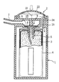
図1は、この発明に係る注出装置の実施形態を示す縦断面図であり、図中1は底壁付きの剛性筒体を、2は、この剛性筒体1の上端部分に嵌まり合う、これも剛性材料を主体とする蓋体をそれぞれ示す。
【0017】
ここで剛性筒体1は、液状物を充填包装した軟質のプラスチック包装袋3を直接的に、または、図示のように、それを箱4に入れたまま間接的に収納するスペースを有する。
【0018】
一方、蓋体2には、その中央部から剛性筒体側へ突出して、プラスチック包装袋3の頂壁に刺さり込む、先細り形状の導出ノズル5を設けるとともに、この導出ノズル5に順次に連通する逆止弁6および注出ノズル7のそれぞれ設け、そして、その逆止弁6を、図では逆止弁ハウジング8に周縁部分で密着するダイアフラム、たとえば0.3〜2.0 mm程度の厚さのシリコーンゴム、エラストマ等よりなる、または、7〜20μm厚みのプラスチックフィルム等からなるダイアフラム9と、このダイアフラム9の、図では上面側に接触して、それの、ハウジング8からの離隔変位を阻止する、これも高剛性の支持部材10とで構成する。
この逆止弁6は、ダイアフラム9への大気圧の作用下では、そのダイアフラム9の周縁部分の、ハウジング8への図示のような密着下で、導出ノズル5と注出ノズル8との連通を遮断する一方で、ダイアフラム9の、図では下面側に作用する袋内液状物の液圧が、そのダイアフラム9の弾性力より大きくなると、ダイアフラム9の周縁部分の、ハウジング8から離隔する方向の弾性変形によって、両ノズル5,7の連通をもたらすべく機能する。この場合、ダイアフラム全体としての、ハウジング8からの離隔変位は、その中央部分に当接する支持部材10によって阻止されることになる。
【0019】
このように構成してなる注出装置において、剛性筒体1および蓋体2のそれぞれに加えて、それら両者の嵌合部もまた高い気密性を有する場合には、筒体1および蓋体2の少なくとも一方、図では蓋体2に大気連通孔11を設けて、軟質のプラスチック包装袋3内の液状物の注出に伴う、その包装袋3の潰れ変形を円滑かつ容易にすることが、液状物の注出の円滑性を確保する上で好ましい。
【0020】
なお、この注出の円滑性は、図示のように、包装袋3を箱4とともに剛性筒体1内へ収納する場合には、その箱4に、一もしくは複数の窓穴12を穿設して、包装袋3への外気の到達をより円滑にすることで十分に担保されることになる。ところで、このような窓穴12は、剛性筒体1を透明材料にて構成したときは、袋内液状物の残量視認用としても利用することができる。
【0021】
また、かかる装置の導出ノズル5の刺込み先端部分13は、円錐形状、角錐形状等に基く、図示のようなテーパ面状または、ストローのような傾斜面状の先細り形状とするとともに、その先端面を曲面形状とすることにより、その刺込み先端部分13を、たとえば、一層もしくは複数層の無延伸フィルムからなる包装袋3に刺し込むに当って、その無延伸フィルムは、曲面形状先端面によって大きく弾性伸長された状態で先端部分13を貫通され、その先端部分13の継続する刺し込みにより、テーパ面状または傾斜面状の先細り部分によって貫通孔をさらに弾性的に拡大されるので、図2に示すような、導出ノズル5の刺し込み状態にあっては、包装袋無延伸フィルム14は、自身の弾性復元力に基いてノズル周面に密着して、それらの間に十分な気密性および液密性をもたらす。
【0022】
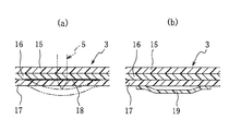
この一方で、プラスチック包装袋3を、たとえば図3に示すように、最外層の延伸ベースフィルム層15と、中間層としての無延伸フィルム層16と、シーラント層としての無延伸フィルム層17との積層構造とするときは、それらの全ての層15,16,17を強固に接合させて積層した場合は、延伸ベースフィルム層15側から、導出ノズル5を図2に示すように刺し込むと、そのベースフィルム層15に亀裂が発生し、その亀裂が、他の無延伸フィルム層16,17に伝播するとともに、広い範囲に進行することになるため、包装袋3と導出ノズル5との間に、上述したような気密性等を確保することが不可能になる。
そこで、図3(a)に示すところでは、積層フィルムの最内層となる無延伸フィルム層17を、導出ノズル5の、所要の刺し込み位置の近傍部分で剥離層18を介して積層し、導出ノズル5の刺し込みに際して、その最内層無延伸フィルム層17を、剥離層18の作用下で、図に仮想線で示すように中間層から簡単に剥離させ得るように構成しており、また、図3(b)に示すところでは、シーラント層のさらに内面に、所要の輪部形状を有する無延伸フィルム19をその周縁部分で気密かつ液密に接合させている。
【0023】
これらのいずれにあっても、最外層側から刺し込んだ導出ノズル5を、無延伸フィルム層17の剥離部分または無延伸フィルム19に、それの弾性域内の伸長変形下で貫通させることにより、先に述べたと同様の気密性等をもたらすことができる。なお、この場合、延伸ベースフィルム層15に強固に接合した無延伸フィルム層16に亀裂の伝播、進行等があっても、それが、無延伸フィルム層17の剥離部分および無延伸フィルム19までは伝播することはなく、また、その亀裂は、それらの剥離部分および付設域の外側へ伝播することもない。
【0024】
ところで、紙製その他の箱4に入れ込んだプラスチック包装袋3に対する、導出ノズル5のこのような刺し込みは、図4に例示するように、箱4の上蓋20の中央部分に、導出ノズル5の進入を許容するスリット21ないしは小孔を予め設けることで、十分円滑にかつ容易に行わせることができる。
【0025】
以上のような注出装置の、図1に示すような適用状態の下での袋内液状物の注出は、図5に示すように、注出装置とともにプラスチック包装袋3を所要に応じて傾動させることによって行うことができ、この場合には、導出ノズル5内へ流入した袋内液状物がダイアフラム9を押圧して、その周縁部分をハウジング8から離隔する方向へ弾性変形させることで、導出ノズル5と注出ノズル7との連通がもたらされるので、その袋内液状物は、注出ノズル7から円滑に注出されることになる。
【0026】
なおこの場合、ダイアフラム全体の、ハウジング8からの逃げ変位は、支持部材10によって確実に阻止されるので、ダイアフラムのこの開放変形および、それの、元形状への後述する弾性復帰のそれぞれは、所期した通りの位置で常に確実に行われることになる。
【0027】
この一方で、所要量の液状物の注出を終えた後は、注出装置を、元の起立姿勢に向けて逆方向に傾動させる。この場合、袋内液状物がダイアフラム9に及ぼす上記押圧力が、ダイアフラム9の自己復帰弾性力よりも小さくなると、そのダイアフラム9は、図1に示すように、周縁部分がハウジング8に接触する常閉姿勢に弾性復帰し、両ノズル5,7の連通を遮断して液状物の注出を停止する。
ここで、ダイアフラム9のこの弾性復帰は、ダイアフラムに固有の弾性復元力もしくは、その弾性復元力と、注出ノズル7から流下する前の液状物重量との和が、袋内液状物のダイアフラム押圧力に勝った時点で直ちに行われるので、液状物の注出の停止に伴う、包装袋3内への外気の侵入は十分に防止されることになり、また、ダイアフラム9の外側へ一旦流出して外気に接触した液状物の、包装袋内への戻流は、閉止姿勢のダイアフラム9をもって確実に阻止されることになる。
【0028】
ところで、袋内への戻流を阻止されてダイアフラム9上に留まることになるこの液状物は、ダイアフラム9の、ハウジング8への密着力を高めることになり、併せて、液状物の注出を、外気の取り込みなしに、体積の低減をもって許容するプラスチック包装袋3の、その注出の停止後の、体積の拡大方向への固有の弾性復元力もまた上記密着力を高める向きの力を発生するので、注出を終えた後のダイアフラム9の、連通遮断機能はより一層高まることになる。
【0029】
かくしてここでは、袋内液体の非注出時には、注出装置を起立姿勢に維持することで、袋内液状物の不測の流出等を確実に防止することができ、また、袋内液状物の注出の停止に伴う、外気および、一旦外気に接した液状物の包装袋内への侵入を、ダイアフラム9の弾性復元力に基いて十分に阻止することができる。
【0030】
図6はこの発明に係る装置の他の実施形態を示す縦断面図であり、これは、図6のVII−VII線に沿う横断面を示す図7の、VI−VI線に沿う断面図である。
これはとくに、蓋体2の頂壁を、気密に取付けた弾性膜体22により構成し、たとえばゴム製とすることができ、上方へドーム状に膨らむこの弾性膜体22の内側を空気室23とするとともに、その空気室23を、蓋体側壁に設けた空気取入口24に連通させたものである。この連通は、空気取入口24を空気室23に直接的に開口させることによって行うこともできるが、ここでは、その空気取入口24を、図7のVIII−VIII線に沿う断面を示す図8に表われる、剛性筒体1への連通路25を介して空気室23に開口させる。なお、図では一個としているこの連通路25は複数個設けることも可能である。
また、この実施形態では、図6に示すように、空気取入口24からの空気の流入は許容するも、そこからの空気の流出は阻止する弁体26、たとえば弾性片を、その取入口24の、剛性筒体側への開口部に設ける。
【0031】
このように構成してなる注出装置は、先に述べたと同様にして、剛性筒体1内へ直接的もしくは間接的に収納したプラスチック包装袋3に導出ノズル5を刺し込むことによって使用に供することができるが、ここでの袋内液状物の注出は、弾性膜体22を、図に仮想線で示すように押圧して、弁体26の作用下で空気室23内の空気を加圧するとともに、その加圧空気を、連通路25を経て剛性筒体1内へ流入させ、それをもって包装袋3を圧潰変形させることにより行うことができ、これによれば、注出装置および包装袋3の傾動操作が不要になる。
【0032】
ところで、包装袋3のこのような圧潰変形は、空気取入口24に弁体26を設けない場合には、その取入口24を、手指によって外側から塞いだ状態で弾性膜体22を押圧変形させることにより行うことができ、これらのいずれの場合にあっても、圧潰変形された包装袋3内の液状物が、それの加圧下で、ダイアフラム9に、先に述べたと同様に、ハウジング8から離隔する方向の弾性変形をもたらすことに基いて、その液状物の注出が行われることになる。
これに対し、注出の停止は、弾性膜体22を押圧力から解放することおよび、空気取入口24の閉塞を解放することの少なくとも一方によって行うことができ、たとえば、弁体26を設けた装置において、弾性膜体22を押圧力から解放したときは、その弾性膜体22は、弁体26の開放下で空気取入口24から外気を取込みながら図に実線で示す元の膨出姿勢に弾性復帰することになり、包装袋3はその間減圧雰囲気におかれることになるので、袋内液状物がダイアフラム9に及ぼす液圧は、弾性膜体22に対する押圧力の解放と同時に急激に低下し、これにより、そのダイアフラム9は、ハウジング8に接触する元形状へ迅速に弾性復帰して両ノズル5,7の連通を直ちに遮断する。従って、ここでの袋内液状物の注出の停止に際してもまた、ダイアフラム9は、包装袋3内への外気および残留液状物の進入に先じてハウジング8に接触することになる。
【0033】
図9は、さらに他の実施形態を示す縦断面図であり、これは、剛性筒体1に空気取入口24を設けるとともに、その空気取入口24の内側に弁体26を設けたものである。
この装置もまた、上述したところと同様に、弾性膜体22の作用下で、装置の傾動操作なしに袋内液状物の注出および停止を行うことができる。
【0034】
以上この発明の実施の形態を図面に示すところに基いて説明したが、図6および9に示すところから弁体26を省くこともでき、この場合には、空気取入口24を所要に応じて手指で塞ぐことで、弾性膜体22に所要の機能を発揮させることができる。
また、それらの図に示すところにおいて、弾性膜体それ自身に、弁体付きのもしくは無しの空気取入口を設けることもできる。
そしてまた、図6および9に示すところに代えて、剛性筒体1、たとえばその側壁に弾性膜体を気密に取付けることもでき、この場合には、弾性膜体の内側の空気室を、筒体側壁に設けた連通路を介して筒体内部に開口させるとともに、その剛性筒体1、蓋体2もしくは弾性膜体それ自身のいずれかに、上述したと同様に機能する弁体付きのまたは弁体無しの空気取入口を設けることで、注出装置を、それらの図に示すものと同様に機能させることができる。
【0035】
【発明の効果】
かくして、この発明によれば、液状物を充填包装した軟質のプラスチック包装袋からのその液状物の注出および、袋内液状物の非注出時の、その包装袋の起立姿勢での保管等を簡易にするとともに、袋内液状物の注出作業、とくに注出の停止に当っての、包装袋内への外気の侵入および、一旦外気に接した液状物の、包装袋内への戻流を逆止弁の作用の下に確実に防止することができる。
【図面の簡単な説明】
【図1】 この発明に係る装置の実施形態を示す縦断面図である。
【図2】 導出ノズルの、包装袋への刺し込み態様を例示する縦断面図である。
【図3】 無延伸フィルム部分の形成態様を例示する断面図である。
【図4】 包装袋を収納する箱を例示する略視図である。
【図5】 液状物の注出状態を示す断面図である。
【図6】 他の実施形態を示す縦断面図である。
【図7】 図6のVII−VII線に沿う断面図である。
【図8】 図6のVIII−VIII線に沿う断面図である。
【図9】 さらに他の実施形態を示す縦断面図である。
【符号の説明】
1 剛性筒体
2 蓋体
3 プラスチック包装袋
4 箱
5 導出ノズル
6 逆止弁
7 注出ノズル
8 逆止弁ハウジング
9 ダイアフラム
10 支持部材
11 大気連通孔
12 窓穴
13 刺込み先端部分
14 包装袋無延伸フィルム
15 延伸ベースフィルム層
16,17 無延伸フィルム層
18 剥離層
19 無延伸フィルム
20 上蓋
21 スリット
22 弾性膜体
23 空気室
24 空気取入口
25 連通路
26 弁体[0001]
BACKGROUND OF THE INVENTION
The present invention relates to, for example, liquids filled and packaged in relatively large soft plastic packaging bags, such as dressings, soups, honey and juices, which may contain various seasonings, alcoholic beverages, granules or powders. In addition, when tea and other items are poured out several times and exhausted, it is easy to pour out and the outside air that may contain microorganisms, dust, etc. enters the plastic packaging bag and The present invention relates to a liquid packaged dispensing device and a dispensing structure for effectively preventing the contacted liquid material from returning to the plastic packaging bag.
[0002]
[Prior art]
When dispensing and using liquids such as detergents and shampoos packed and packaged in relatively large, soft plastic packaging bags, the dispensing operation is facilitated, and from a single dispensing, Various liquid take-out devices made of hard materials that can store plastic packaging bags have been proposed in order to facilitate the storage of plastic packaging bags in an upright position until the next dispensing operation. Yes.
[0003]
However, detergents, shampoos, etc. are not as affected as food and drink by oxidation due to the outside air and intrusion of dust etc. into plastic packaging bags, and various measures are taken for detergents, etc. since it is possible, many, the dispensing means comprising a tube and a pump member narrowing stabbed into the packaging bag, no strict ambient air barrier properties and the like are applied, the product rather to the packaging bag in Kyokuteki In general, it is common practice to discharge detergent or the like by compressing the outside air taken in the pump by a pump member.
[0004]
In contrast, the packaged articles are beverage, when a seasoning or the like, for each time of the dispense, the outside air incorporation into the packaging bag in the oxidation of the liquid material by the outside air itself, its taste, In addition to causing a decrease in flavor and the like, the liquid material may be soiled or corroded by microorganisms, dust, or the like that may be contained in the outside air.
[0005]
Therefore, JP-A-8-133307 discloses a valve chamber having an upper diameter-expanded portion and a lower-diameter portion for the purpose of preventing the outside air from entering the container every time the liquid is poured out. It has been proposed to attach a check valve configured by arranging a spherical valve body to a spout of a bag-like container.
This check valve allows the liquid material to be dispensed by rolling the valve body to the upper diameter-expanded portion of the valve chamber by tilting the container when the liquid material is dispensed. When the valve body rolls to the lower small diameter part of the valve chamber by returning the container to the standing posture, a part of the liquid remaining in the discharge port is sucked into the valve chamber, and the liquid level in the discharge port is kept inside. It is intended to retreat back.
[0006]
[Problems to be solved by the invention]
However, according to this proposed technology, the check valve is returned to a posture in which the upper diameter-expanded portion faces upward so that the liquid material is completely dispensed and the valve body in the valve chamber is moved back to the lower-diameter portion. When doing so, the situation where the outside air that may contain microorganisms and the liquid material that has been in contact with the outside air inevitably enters the container through the valve chamber, There was still a risk of oxidation by outside air and contamination by microorganisms.
[0007]
An object of the present invention is to solve such problems of the prior art, and the object of the present invention is to inject a liquid material filled and packaged in a relatively large flexible plastic packaging bag. Makes it easy for the packing bag to stand upright and store it between one and the next, as well as for the outside air to enter the packaging bag during the pouring operation. Provided is a liquid packaged dispensing device and a dispensing structure that reliably prevent the liquid in contact with the liquid from returning to the plastic packaging bag and sufficiently eliminate the risk of oxidation and contamination of the liquid in the bag. It is in.
[0008]
[Means for Solving the Problems]
According to the present invention, a liquid packaged dispensing device includes a rigid cylindrical body with a bottom wall that stores a soft plastic packaging bag filled and packaged with a liquid material directly or indirectly via a packaging box or the like. And a lid that fits into the upper end portion of the rigid cylindrical body, and the lid is provided with a lead-out nozzle that is inserted into the plastic packaging bag, and a check valve and a dispensing nozzle that are sequentially communicated with the lead-out nozzle A diaphragm that elastically deforms at a peripheral portion between a closed position that blocks communication between the lead-out nozzle and the dispensing nozzle and an open position that provides communication between the check nozzle and the check valve. constituted by a support member to restrain the displacement of the diaphragm in contact with the central portion of the diaphragm, the barbs inclusive tip of deriving the nozzle, with a tapered face shaped or inclined surfaces shaped tapered, its It is made of a tip a curved shape.
In this apparatus, a lead-out nozzle is inserted into a plastic packaging bag in a rigid cylinder, and a soft plastic packaging bag filled and packaged with a liquid material is fitted under the action of the rigid cylinder by fitting a lid to the rigid cylinder. It is possible to stably maintain the standing posture and wait for the liquid material in the bag to be poured out as required, so that it is possible to prevent unexpected liquid spillage due to the fall of the soft plastic packaging bag, etc. Can be prevented.
[0009]
Also, under this standing posture of the packaging bag, based on the normally closed function of the check valve provided on the lid, the diaphragm is brought into close contact with the housing under the action of atmospheric pressure there, and the discharge nozzle and the dispensing nozzle because it cuts off the communication between the outside care, etc. will not be entering into the packaging bag in.
On the other hand, the liquid material in the bag can be poured by grasping the rigid cylinder and tilting the cylinder, and thus the packaging bag, so that the dispensing is also easy and stable. Can be done automatically.
Here, when this liquid material is poured out, the liquid material that has flowed into the outlet nozzle exerts a hydraulic pressure on the diaphragm constituted by a plastic film, a rubber sheet, etc., and this is restrained by the displacement of the support member. Underneath, the bag is elastically deformed in the opening direction, so that the liquid in the bag can flow out smoothly from the outlet nozzle through the check valve and the dispensing nozzle without being affected by the diaphragm.
[0010]
On the other hand, when the required amount of liquid material has been poured out and the rigid cylinder and the packaging bag are turned and displaced in their upright directions, the elastic restoring force of the diaphragm to the original shape causes the liquid material in the outlet nozzle to move. When the fluid pressure exerted on the diaphragm exceeds the diaphragm, the diaphragm is closely attached to the housing at its peripheral edge based on the normally closed function of the check valve, and the communication between the outlet nozzle and the dispensing nozzle is completely blocked. To do.
[0011]
By the way, such pouring of the liquid material in the bag under the high flexibility of the packaging bag, the packaging bag itself contracts by an amount corresponding to the volume of the pouring liquid without taking in outside air into the bag. As a result, the soft packaging bag has a reduced-pressure atmosphere inside the bag based on its inherent elastic restoring force. Therefore, the diaphragm is adsorbed and held by the housing, so that the communication between both nozzles is more reliably cut off.
Thus, in this case, not only the liquid material is being poured out, but also when the dispensing is stopped, the intrusion of outside air into the packaging bag is sufficiently prevented based on the elastic return of the diaphragm to its original shape. As a result, the risk of oxidation, fouling, etc. of the liquid in the bag due to outside air can be effectively removed.
[0012]
In addition, even when the liquid material is left outside the diaphragm when the liquid material is stopped to be poured, the residual liquid material is further increased by the action of its weight on the diaphragm. Since adhesion is brought about, the return flow of the residual liquid material to the packaging bag is surely prevented.
[0013]
In the above-described dispensing device, an elastic film body is preferably attached airtightly to either the lid body or the rigid cylinder body, and the elastic film body itself, the rigid cylinder body or the lid body is elastically attached. When providing an air intake that allows the inflow of air to the inside of the film body and a communication path that allows the air inside the elastic film body to flow into the rigid cylindrical body, By pushing and deforming the elastic film body while the air intake is closed, the air taken in via the air intake can flow into the rigid cylinder through the communication path. Can press the plastic packaging bag. Therefore, in this case, the elastic film body is pushed and deformed while maintaining the pouring device and the packaging bag in an upright posture, thereby applying a compressive force to the liquid material in the bag, and pouring the liquid material through the diaphragm. It can flow out from the exit nozzle.
And, such stopping of the pouring is performed by releasing the plastic packaging bag and the liquid material in the bag from the action of the compressive force by stopping the pushing of the elastic film body, opening the air intake port, etc. Even when such pouring is stopped, the diaphragm elastically recovers as the hydraulic pressure acting on the diaphragm decreases, blocking the communication between the two nozzles, so that the outside air can enter the packaging bag. Can be sufficiently prevented.
[0014]
Here, it is preferable to provide a valve body that prevents the air once taken into the elastic film body from the air intake port from flowing out to the outside, for example, a plastic film or other thin film. According to this, when the elastic film body is pushed and deformed, the air inside the elastic film body can be smoothly and surely flowed into the rigid cylinder body without closing the air intake port with fingers. Therefore, the liquid material can be poured out more easily.
However here, the barbs inclusive tip of deriving the nozzle, a conical shape, with a tapered face shaped or inclined surfaces shaped tapered based pyramid shape or the like, by that its tip a curved shape, a plastic packing bag When inserting the lead-out nozzle into the unstretched film of itself or attached thereto, the unstretched film can be elastically stretched greatly with a curved tip surface, and the tapered end of the tapered surface or inclined surface Since the unstretched film can be elastically stretched more greatly by inserting the portion into the unstretched film, the packaging bag in which the lead-out nozzle is inserted is It is possible to secure a good airtightness between them by closely adhering to the surroundings.
[0015]
The liquid package dispensing structure according to the present invention has the plastic packaging bag itself around the tip of the outlet nozzle inserted into the plastic packaging bag of any of the above-described dispensing devices. Or an unstretched film attached thereto is elastically adhered. According to this configuration, as described above, the airtightness between the lead-out nozzle and the non-stretched film can be improved, and entry of outside air into the packaging bag from between them can be sufficiently prevented.
[0016]
DETAILED DESCRIPTION OF THE INVENTION
Embodiments of the present invention will be described below with reference to the drawings.
FIG. 1 is a longitudinal sectional view showing an embodiment of a pouring device according to the present invention, in which 1 is fitted to a rigid cylinder with a bottom wall, and 2 is fitted to the upper end portion of the rigid cylinder 1. This also shows a lid mainly composed of a rigid material.
[0017]
Here, the rigid cylindrical body 1 has a space for storing the soft
[0018]
On the other hand, the lid 2 is provided with a tapered lead-out
Under the action of atmospheric pressure on the
[0019]
In the pouring device configured as described above, in addition to each of the rigid cylinder 1 and the lid 2, when both of the fitting portions also have high airtightness, the cylinder 1 and the lid 2. In at least one of the figures, the
[0020]
As shown in the drawing, when the
[0021]
Further, the
[0022]
On the other hand, as shown in FIG. 3, for example, the
Therefore, as shown in FIG. 3A, the
[0023]
In any of these cases, the lead-out
[0024]
By the way, such insertion of the
[0025]
The dispensing of the liquid material in the bag under the application state as shown in FIG. 1 of the above-described dispensing device, as shown in FIG. In this case, the liquid material in the bag that has flowed into the
[0026]
In this case, since the escape displacement of the entire diaphragm from the housing 8 is reliably prevented by the
[0027]
On the other hand, after finishing dispensing the required amount of liquid material, the pouring device is tilted in the reverse direction toward the original standing posture. In this case, when the pressing force exerted on the
Here, this elastic return of the
[0028]
By the way, this liquid material that is prevented from flowing back into the bag and stays on the
[0029]
Thus, in this case, when the liquid in the bag is not poured out, by keeping the pouring device in an upright position, it is possible to surely prevent the liquid material in the bag from being accidentally leaked out. Based on the elastic restoring force of the
[0030]
6 is a longitudinal sectional view showing another embodiment of the apparatus according to the present invention, which is a sectional view taken along the line VI-VI in FIG. 7 showing a transverse section taken along the line VII-VII in FIG. is there.
In particular, the top wall of the lid 2 is formed of an
Further, in this embodiment, as shown in FIG. 6, a
[0031]
The pouring device configured as described above is used by inserting the
[0032]
By the way, such a crushing deformation of the
On the other hand, the stopping of the pouring can be performed by at least one of releasing the
[0033]
FIG. 9 is a longitudinal sectional view showing still another embodiment, which is provided with an
Similarly to the above, this apparatus can also pour out and stop the liquid material in the bag without the tilting operation of the apparatus under the action of the
[0034]
Although the embodiment of the present invention has been described with reference to the drawings, the
Moreover, in the place shown in those figures, the elastic film body itself can be provided with an air intake with or without a valve body.
6 and 9, an elastic film body can be airtightly attached to the rigid cylinder 1, for example, the side wall thereof. In this case, the air chamber inside the elastic film body is connected to the cylinder. With the valve body functioning in the same manner as described above, the rigid cylindrical body 1, the lid body 2 or the elastic film body itself is opened to the inside of the cylindrical body through the communication path provided in the body side wall. By providing the air intake without a valve body, the extraction device can function in the same manner as those shown in the drawings.
[0035]
【The invention's effect】
Thus, according to the present invention, the liquid material is poured out from the soft plastic packaging bag filled and packaged with the liquid material, and the packaging bag is stored in an upright position when the liquid material in the bag is not poured out. In addition, the liquid in the bag is poured out, especially when the outside of the bag is stopped, and the liquid that has been in contact with the outside air is returned to the bag. Flow can be reliably prevented under the action of a check valve.
[Brief description of the drawings]
FIG. 1 is a longitudinal sectional view showing an embodiment of an apparatus according to the present invention.
FIG. 2 is a longitudinal cross-sectional view illustrating an example of how a lead-out nozzle is inserted into a packaging bag.
FIG. 3 is a cross-sectional view illustrating an embodiment of forming an unstretched film portion.
FIG. 4 is a schematic view illustrating a box for storing a packaging bag.
FIG. 5 is a cross-sectional view showing a liquid material being poured out.
FIG. 6 is a longitudinal sectional view showing another embodiment.
7 is a cross-sectional view taken along line VII-VII in FIG.
8 is a cross-sectional view taken along line VIII-VIII in FIG.
FIG. 9 is a longitudinal sectional view showing still another embodiment.
[Explanation of symbols]
DESCRIPTION OF SYMBOLS 1 Rigid cylinder 2
Claims (5)
Priority Applications (1)
| Application Number | Priority Date | Filing Date | Title |
|---|---|---|---|
| JP2002156713A JP4116331B2 (en) | 2002-05-30 | 2002-05-30 | Liquid packaging device and structure |
Applications Claiming Priority (1)
| Application Number | Priority Date | Filing Date | Title |
|---|---|---|---|
| JP2002156713A JP4116331B2 (en) | 2002-05-30 | 2002-05-30 | Liquid packaging device and structure |
Publications (2)
| Publication Number | Publication Date |
|---|---|
| JP2004001788A JP2004001788A (en) | 2004-01-08 |
| JP4116331B2 true JP4116331B2 (en) | 2008-07-09 |
Family
ID=30428347
Family Applications (1)
| Application Number | Title | Priority Date | Filing Date |
|---|---|---|---|
| JP2002156713A Expired - Fee Related JP4116331B2 (en) | 2002-05-30 | 2002-05-30 | Liquid packaging device and structure |
Country Status (1)
| Country | Link |
|---|---|
| JP (1) | JP4116331B2 (en) |
Families Citing this family (6)
| Publication number | Priority date | Publication date | Assignee | Title |
|---|---|---|---|---|
| JP5483191B2 (en) * | 2010-03-31 | 2014-05-07 | 株式会社吉野工業所 | Pouring cap |
| JP6592280B2 (en) * | 2015-06-11 | 2019-10-16 | 株式会社ニイタカ | Injection bottle |
| CN111094147B (en) * | 2017-03-30 | 2022-08-12 | 1泰驰控股有限公司 | Self-sealing airless metering dispenser |
| WO2020027567A1 (en) * | 2018-07-31 | 2020-02-06 | 박문식 | Tumbler for preparing beverage and additive-storing capsule therefor |
| US11871874B2 (en) | 2018-07-31 | 2024-01-16 | Moon Sik PARK | Tumbler for preparing beverage and additive-storing capsule therefor |
| CN114849465B (en) * | 2022-04-15 | 2023-09-08 | 佛山市蓝宇环保科技有限公司 | Energy recovery type energy-saving environment-friendly waste gas treatment spray tower |
-
2002
- 2002-05-30 JP JP2002156713A patent/JP4116331B2/en not_active Expired - Fee Related
Also Published As
| Publication number | Publication date |
|---|---|
| JP2004001788A (en) | 2004-01-08 |
Similar Documents
| Publication | Publication Date | Title |
|---|---|---|
| JP4996815B2 (en) | Liquid pouring nozzle, packaging bag using the same, and method of using the packaging bag | |
| KR101572047B1 (en) | Pour channel with cohesive closure valve and locking bubble | |
| JP4490493B2 (en) | Flexible packaging bag with check function nozzle | |
| KR101110521B1 (en) | Liquid spouting nozzle, and packaging bag using the nozzle | |
| US20130181005A1 (en) | No straw liquid pouch | |
| NO161110B (en) | PACKAGING WITH SORTING DEVICE. | |
| JP2014522787A (en) | Hygienic removal package | |
| JP2011073770A (en) | Blow molded bottle body with pouring cap | |
| WO2013019362A2 (en) | Flowable Dispensers, Systems, and Filling Processes | |
| JP6150227B2 (en) | Packaging bag for quantitative dispensing | |
| JP4116331B2 (en) | Liquid packaging device and structure | |
| JP2011509893A (en) | Pouring package and pouring member | |
| JP5344761B2 (en) | Double-pack packaging bag for drinking water and packaging structure for filling with drinking water and extraction material | |
| US7922045B2 (en) | Condiment packet | |
| WO2010150911A1 (en) | Free-standing liquid packaging pouch with a flat film valve | |
| JP5477700B2 (en) | Dispensing container | |
| JP5175382B2 (en) | Liquid pouring nozzle | |
| JPH1072044A (en) | Food container | |
| JP4699463B2 (en) | Pouring package and pouring member | |
| JP2003026266A (en) | Liquid pour-out device | |
| JP5544624B2 (en) | Double pack packaging structure for seasoning liquid with broth material | |
| JP3204404U (en) | Liquid container | |
| JP2004074541A (en) | Packaging film | |
| WO2003095317A1 (en) | Pack container for beverage and others for spout prevention, tube such as straw for pack container for spout prevention, and pack container with tube such as straw for spout prevention | |
| KR20100083891A (en) | Sticker type check valve for vacuum bag and vacuum bag sealing set using the same |
Legal Events
| Date | Code | Title | Description |
|---|---|---|---|
| A621 | Written request for application examination |
Free format text: JAPANESE INTERMEDIATE CODE: A621 Effective date: 20050518 |
|
| A977 | Report on retrieval |
Free format text: JAPANESE INTERMEDIATE CODE: A971007 Effective date: 20070705 |
|
| A131 | Notification of reasons for refusal |
Free format text: JAPANESE INTERMEDIATE CODE: A131 Effective date: 20070807 |
|
| A711 | Notification of change in applicant |
Free format text: JAPANESE INTERMEDIATE CODE: A711 Effective date: 20071002 |
|
| A521 | Written amendment |
Free format text: JAPANESE INTERMEDIATE CODE: A523 Effective date: 20071004 |
|
| A521 | Written amendment |
Free format text: JAPANESE INTERMEDIATE CODE: A821 Effective date: 20071002 |
|
| TRDD | Decision of grant or rejection written | ||
| A01 | Written decision to grant a patent or to grant a registration (utility model) |
Free format text: JAPANESE INTERMEDIATE CODE: A01 Effective date: 20080415 |
|
| A61 | First payment of annual fees (during grant procedure) |
Free format text: JAPANESE INTERMEDIATE CODE: A61 Effective date: 20080417 |
|
| FPAY | Renewal fee payment (event date is renewal date of database) |
Free format text: PAYMENT UNTIL: 20110425 Year of fee payment: 3 |
|
| R150 | Certificate of patent or registration of utility model |
Free format text: JAPANESE INTERMEDIATE CODE: R150 |
|
| FPAY | Renewal fee payment (event date is renewal date of database) |
Free format text: PAYMENT UNTIL: 20110425 Year of fee payment: 3 |
|
| LAPS | Cancellation because of no payment of annual fees |