JP4111890B2 - Uninterruptible power system - Google Patents
Uninterruptible power system Download PDFInfo
- Publication number
- JP4111890B2 JP4111890B2 JP2003282088A JP2003282088A JP4111890B2 JP 4111890 B2 JP4111890 B2 JP 4111890B2 JP 2003282088 A JP2003282088 A JP 2003282088A JP 2003282088 A JP2003282088 A JP 2003282088A JP 4111890 B2 JP4111890 B2 JP 4111890B2
- Authority
- JP
- Japan
- Prior art keywords
- secondary battery
- power
- power supply
- electronic device
- signal
- Prior art date
- Legal status (The legal status is an assumption and is not a legal conclusion. Google has not performed a legal analysis and makes no representation as to the accuracy of the status listed.)
- Expired - Fee Related
Links
Images


Classifications
-
- H—ELECTRICITY
- H02—GENERATION; CONVERSION OR DISTRIBUTION OF ELECTRIC POWER
- H02J—CIRCUIT ARRANGEMENTS OR SYSTEMS FOR SUPPLYING OR DISTRIBUTING ELECTRIC POWER; SYSTEMS FOR STORING ELECTRIC ENERGY
- H02J9/00—Circuit arrangements for emergency or stand-by power supply, e.g. for emergency lighting
- H02J9/04—Circuit arrangements for emergency or stand-by power supply, e.g. for emergency lighting in which the distribution system is disconnected from the normal source and connected to a standby source
- H02J9/06—Circuit arrangements for emergency or stand-by power supply, e.g. for emergency lighting in which the distribution system is disconnected from the normal source and connected to a standby source with automatic change-over, e.g. UPS systems
- H02J9/061—Circuit arrangements for emergency or stand-by power supply, e.g. for emergency lighting in which the distribution system is disconnected from the normal source and connected to a standby source with automatic change-over, e.g. UPS systems for DC powered loads
Description
本発明は、電力源の停電からコンピュータ等の電子機器を効果的にバックアップすることができ、しかもその省電力化を図ることのできる無停電電源装置に関する。 The present invention relates to an uninterruptible power supply that can effectively back up electronic equipment such as a computer from a power failure of a power source and can save power.
電力源として商用電源(交流)を用いたパーソナルコンピュータやサーバ等の電子機器においては、その動作(稼動)中に瞬時停電等が発生すると、処理動作自体にエラーが生じたり、貴重な処理データが損なわれる等の不具合が発生する。そこでこの種の電子機器の電源系に二次電池を備えた無停電電源装置を設け、商用電源の停電時には上記二次電池から電子機器に対して電力を供給することで該電子機器の処理動作を保証し、またその処理データを保護することが種々試みられている(例えば特許文献1,2を参照)。
In an electronic device such as a personal computer or server using a commercial power source (AC) as a power source, if an instantaneous power failure occurs during its operation (operation), an error occurs in the processing operation itself, or valuable processing data is lost. Problems such as damage occur. Therefore, an uninterruptible power supply device equipped with a secondary battery is provided in the power supply system of this type of electronic equipment, and processing operation of the electronic equipment is performed by supplying power from the secondary battery to the electronic equipment at the time of a power failure of the commercial power supply. Various attempts have been made to guarantee the above and to protect the processed data (see, for example,
ちなみにこの種の無停電電源装置は、商用電源から得られる電力エネルギにて二次電池を充電しておき、停電時には上記二次電池に蓄積した電力エネルギを電子機器に供給(放電)することで、該電子機器が動作するに必要な電力をバックアップするように構成される。また二次電池に蓄積した電力エネルギの無駄な消費を防ぐべく、例えば電子機器がデータ保存等の所定の処理を実行して停止するまでの期間に亘って電力を供給した後、その動作を停止するように無停電電源装置を構成することもある。
ところで上述したようにバックアップ期間の経過後に無停電電源装置の動作を停止させると、二次電池の状態監視機能も停止するので該二次電池の充電状態をモニタすることもできなくなる。そこで無停電電源装置の動作停止時に、例えば二次電池の状態(電池電圧や残容量等)を示す情報を、EEPROMやフラッシュメモリ等の不揮発性記憶装置を用いて保存することが考えられている。しかしこの種の不揮発性記憶装置へのデータの書き込みには時間が掛かることが否めない。しかも無停電電源装置を長期間(例えば数ヶ月以上)に亘って起動しなかった場合、二次電池の自己放電によって前記不揮発性記憶装置に記憶された二次電池の状態と、実際の二次電池の状態とが大きく異なってしまう。 By the way, as described above, when the operation of the uninterruptible power supply is stopped after the backup period has elapsed, the state monitoring function of the secondary battery is also stopped, so that the state of charge of the secondary battery cannot be monitored. Therefore, when the operation of the uninterruptible power supply is stopped, for example, it is considered to store information indicating the state of the secondary battery (battery voltage, remaining capacity, etc.) using a nonvolatile storage device such as an EEPROM or a flash memory. . However, it cannot be denied that it takes time to write data to this type of nonvolatile storage device. In addition, when the uninterruptible power supply is not started for a long period of time (for example, several months or more), the state of the secondary battery stored in the nonvolatile storage device by the self-discharge of the secondary battery and the actual secondary The battery state is very different.
本発明はこのような事情を考慮してなされたもので、その目的は、二次電池に蓄えられた電力エネルギの無駄な消費を抑えながら、外部電源入力が途絶えたときから再度外部電源入力が加えられた際、二次電池に対する充電制御を円滑に再開することのできる無停電電源装置を提供することにある。 The present invention has been made in view of such circumstances, and the purpose of the present invention is to reconnect the external power input after the external power input is interrupted while suppressing wasteful consumption of power energy stored in the secondary battery. An object of the present invention is to provide an uninterruptible power supply capable of smoothly restarting charging control for a secondary battery when added.
上述した目的を達成するべく本発明に係る無停電電源装置は、商用電源等の外部電源入力を受けて所定の電子機器に電力を供給する電源回路と、前記外部電源入力から得られる電力エネルギを蓄える(充電する)と共に、前記電源回路への前記外部電源入力が途絶えたときに該電源回路に代わって前記電子機器に電力を供給する(放電する)二次電池とを備えたものであって、
前記外部電源入力から得られる電力、または前記二次電池から得られる電力を受けて動作する電子回路であって、前記二次電池の充電状態(例えば電池電圧や電池温度、充放電電流等)に応じて該二次電池に対する充電を制御すると共に、前記二次電池から前記電子機器への電力供給を制御する制御手段(充電制御機能およびバックアップ制御機能)と、
前記電源回路への前記外部電源入力が途絶えたとき、前記電子機器と前記制御手段の一方または両方に対して電源遮断信号を出力する電源遮断検出部と、前記電源遮断信号の発生タイミングから一定時間後、または前記電子機器からシャットダウン信号が与えられてから一定時間後に前記制御手段への電力供給を停止させるタイマー手段(動作制御機能)とを備えたことを特徴としている。そして前記制御手段においては、前記一定時間内であれば前記二次電池の状態を記憶し、前記一定時間の経過後であれば信頼性が乏しいとして前記二次電池の状態を記憶しないようにしたことを特徴としている。
In order to achieve the above-described object, an uninterruptible power supply according to the present invention includes a power supply circuit that receives an external power supply input such as a commercial power supply and supplies power to a predetermined electronic device, and power energy obtained from the external power supply input. A secondary battery that stores (charges) and supplies (discharges) electric power to the electronic device instead of the power supply circuit when the external power input to the power supply circuit is interrupted. ,
An electronic circuit that operates by receiving electric power obtained from the external power supply input or electric power obtained from the secondary battery, and is in a charged state of the secondary battery (for example, battery voltage, battery temperature, charge / discharge current, etc.) In response to controlling the charging of the secondary battery, the control means (charging control function and backup control function) for controlling the power supply from the secondary battery to the electronic device,
A power-off detector that outputs a power-off signal to one or both of the electronic device and the control means when the external power input to the power circuit is interrupted; and a predetermined time from the generation timing of the power-off signal Or a timer means (operation control function) for stopping the power supply to the control means after a predetermined time after the shutdown signal is given from the electronic device. In the control means, the state of the secondary battery is stored within the predetermined time, and the state of the secondary battery is not stored because the reliability is poor after the predetermined time has elapsed. It is characterized by that.
ちなみに前記制御手段については、前記電子機器からシャットダウン信号が与えられたとき、または前記電源遮断信号を受けた前記電子機器が所定の処理を完了するまでの時間を見込んで前記二次電池から前記電子機器への電力供給を停止させ、これによって前記二次電池に蓄積した電力エネルギの無駄な消費を防ぐ役割を担うものとして構成することが望ましい。 Incidentally, with respect to the control means, when the shutdown signal is given from the electronic device, or when the electronic device that has received the power cutoff signal expects the time until the electronic device completes a predetermined process, It is desirable that the power supply to the device is stopped, and thereby configured to play a role of preventing wasteful consumption of the power energy accumulated in the secondary battery.
また前記制御手段においては、前記電源遮断信号の発生後、前記一定時間内に前記外部電源入力が再度加えられた際には、記憶した前記二次電池の状態の情報に従って前記二次電池に対する充電制御を再開するようにし、また前記電源遮断信号の発生後から一定時間経過後に前記外部電源入力が再度加えられた際には、前記二次電池の状態を検出し直して該二次電池に対する充電制御を開始するように構成することが望ましい。このとき、電池電圧から残容量を求めて、前記二次電池の状態を検出し直す。
二次電池の状態として、残容量を用いる。
Further, in the control means, when the external power input is applied again within the predetermined time after the generation of the power cutoff signal, the secondary battery is charged according to the stored state information of the secondary battery. Control is resumed, and when the external power input is applied again after a lapse of a certain time from the occurrence of the power shutoff signal, the state of the secondary battery is detected again to charge the secondary battery. it is desirable to by sea urchin configuration you start the control. At this time, the remaining capacity is obtained from the battery voltage, and the state of the secondary battery is detected again.
The remaining capacity is used as the state of the secondary battery.
このように構成された無停電電源装置によれば、電子機器に対して二次電池からバックアップ用の電力を所定期間に亘って供給するだけであり、また電源遮断信号の発生タイミングから一定時間後、或いは前記電子機器からシャットダウン信号が与えられてから一定時間後に前記制御手段への電力供給を停止させるので、二次電池に蓄えられた電力エネルギの無駄な消費を効果的に抑えることができる。 According to the uninterruptible power supply apparatus configured in this way, only the backup power is supplied from the secondary battery to the electronic device over a predetermined period, and after a certain time from the generation timing of the power cut-off signal. Alternatively, since the power supply to the control means is stopped after a predetermined time since the shutdown signal is given from the electronic device, wasteful consumption of the power energy stored in the secondary battery can be effectively suppressed.
また制御手段に対しては一定時間に亘って電力が供給されているので、該制御手段に不揮発性記憶装置を組み込まなくても、例えば制御手段への電力供給を停止させる前に外部電源入力が加えられて無停電電源装置が再起動される場合には、前記制御手段が取得している二次電池の状態を示す情報に従って速やかに該二次電池に対する充電制御を開始することができる。そして制御手段に対する電力供給を停止させた後に外部電源入力が加えられて無停電電源装置が再起動された場合にだけ、制御手段に二次電池の状態を示す情報が失われているので、二次電池の状態を改めて検出して二次電池に対する充電制御を開始すれば良い。従って信頼性のない情報に従って充電制御を実行するような不具合を招来することがない。 In addition, since power is supplied to the control means for a certain period of time, an external power input can be made before the power supply to the control means is stopped, for example, without incorporating a non-volatile storage device in the control means. In addition, when the uninterruptible power supply is restarted, charging control for the secondary battery can be started promptly according to the information indicating the state of the secondary battery acquired by the control means. Since the information indicating the state of the secondary battery is lost to the control means only when the external power input is applied after the power supply to the control means is stopped and the uninterruptible power supply is restarted, What is necessary is just to detect the state of a secondary battery again and to start charge control with respect to a secondary battery. Therefore, there is no inconvenience that the charging control is executed according to the unreliable information.
ちなみに前記制御手段への電力供給を停止させるまでの期間については、例えば月曜日の朝に無停電電源装置のスイッチを投入し、金曜日の夕方にスイッチを切るような操作を定期的に繰り返して行うような場合、70時間程度として設定しておけば十分である。このような定常的な供し時間を見込んだ時間を設定しておけば、無停電電源装置を起動する都度、二次電池の状態を検出すると言う煩わしさをなくすことができ、停止時の情報をそのまま活用して二次電池を充電制御することが可能となる。 By the way, regarding the period until the power supply to the control means is stopped, for example, the operation of turning on the uninterruptible power supply on Monday morning and turning it off on Friday evening should be repeated periodically. In such a case, it is sufficient to set it as about 70 hours. By setting a time that allows for such regular service time, the troublesomeness of detecting the state of the secondary battery every time the uninterruptible power supply is started can be eliminated. It is possible to control charging of the secondary battery by utilizing it as it is.
以下、図面を参照して本発明の一実施形態に係る無停電電源装置について説明する。
図1はこの実施形態に係る無停電電源装置の要部概略構成図で、1はこの無停電電源装置がバックアップ対象とするコンピュータ等の電子機器(負荷)である。無停電電源装置は、基本的には外部電源入力である商用電源(交流)を所定の直流電圧Vaに変換して電子機器1に電力供給する電源回路2と、通常時に上記商用電源の電力エネルギを蓄積(充電)すると共に、前記商用電源の遮断時には蓄積した電力エネルギを前記電子機器1に供給(放電)する二次電池(BAT)3とを備える。また無停電電源装置は、前記商用電源の停電または手動スイッチAの操作による遮断を検出して電源遮断信号を発生し、この遮断信号を制御回路10に与える電源遮断検出回路(電源遮断検出部)4を備える。
Hereinafter, an uninterruptible power supply according to an embodiment of the present invention will be described with reference to the drawings.
FIG. 1 is a schematic configuration diagram of a main part of an uninterruptible power supply according to this embodiment.
電源回路2は、インバータ回路等によって構成されるAC/DC変換器からなり、この電源回路2にて生成された直流電力(直流電圧)VaはダイオードD1を順方向に介して電子機器1に供給される。またNi-MH電池やLiイオン電池等からなる二次電池3は、上記電源回路2にて生成された直流電力をMOS-FET等からなる充電制御用のスイッチ素子5を介して入力して充電し、これを電力エネルギとして蓄える。そしてこの二次電池3に蓄えられた電力エネルギ(直流電圧)Vbは、後述する出力制御用のスイッチ11からダイオードD2を順方向に介して前記電子機器2に出力されるようになっている。
The
尚、二次電池3にはシャント抵抗6が直列に接続されており、このシャント抵抗6を介して二次電池3の充放電電流Iが検出されるようになっている。また二次電池3の近傍にはサーミスタ等の温度センサ7が設けられており、この温度センサ7を介して二次電池3の電池温度Tが検出されるようになっている。この充放電電流Iおよび電池温度Tは、二次電池3の電池電圧Vと共に、後述する二次電池3の充電状態を示す情報としてその充電制御に用いられる。
Note that a shunt resistor 6 is connected in series to the
さて二次電池3の電池電圧や残容量等の充電状態に応じて該二次電池3に対する充電を制御すると共に、前記二次電池3から前記電子機器1への電力供給を制御する制御回路(制御手段)10は、前記電源回路2が生成した直流電力(直流電圧)VaをダイオードD3を介して入力し、或いは前記二次電池3に蓄えられた直流電力エネルギ(直流電圧)VbをダイオードD4を介して入力し、これを電力源として動作する。特にこの制御回路10は、電源制御部12によりオン・オフ制御される内部電源スイッチ13を介して前記電源回路2または二次電池3からの直流電力Va,Vbを内部電源回路14に入力し、この内部電源回路14にて該制御回路10の作動に必要な内部電源電圧Vcを生成して動作する。
A control circuit for controlling the charging of the
この制御回路10は、前述した二次電池3の電池電圧V、充放電電流Iおよび電池温度Tを検出した該二次電池3の電池状態を監視する電池状態監視部15と、この電池状態監視部15による監視結果に従って前記充電制御用のスイッチ素子5をオン・オフして前記二次電池3に対する充電を制御する充電制御部16とを備える。この充電制御部16は、電池電圧Vの変化や電池温度Tの変化等に従って二次電池3の満充電状態を判定して二次電池3の過充電を防止したり、或いは電池電圧Vとその充放電電流I等から求められる二次電池3の充電容量(残容量)に応じて該二次電池3に対する充電を実行することで、その過放電を防止しながら二次電池3の充電容量を一定値以上に保つ等の役割を担う。
The
尚、この二次電池3に対する充電制御については、従来より種々提唱されている一般的な手法を適宜採用すれば良い。またこの実施形態においては、電池状態監視部15はシャント抵抗6に発生する電圧を図示しない内部メモリに記憶し、更に一定時間毎に電池温度Tやその周囲温度を検出して、その温度分布等を上記内部メモリに記憶している。更に電池状態監視部15においては、電池電圧異常、電池温度異常、充放電電流異常、電源温度異常等の異常状態を検出し、これをアラーム情報として記憶するものとなっている。これらの内部メモリに記憶された情報は、電池状態監視情報として図示しない表示部に表示される。
In addition, about the charge control with respect to this
ちなみに本実施形態においては、無停電電源装置、およびコンピュータである電子機器1の停止や停電の形態については、下記の(a)(b)(c)を想定している。
(a) 電子機器1がオン状態で、停電が発生した場合
(b) 電子機器がオン状態で、手動スイッチAをオフにする場合
(c) 電子機器1をオフにしてから、手動スイッチAをオフにする場合
そこで上記(a),(b)のケースについて以下に説明する。
Incidentally, in the present embodiment, the following (a), (b), and (c) are assumed for the uninterruptible power supply and the form of stoppage or power failure of the
(a) When a power failure occurs while the
(b) When electronic switch is on and manual switch A is turned off
(c) When turning off the
さて基本的には上述した機能を備えて構成される本発明の無停電電源装置が特徴とするところは、前述した制御回路10が、電源遮断検出回路4から遮断信号を入力し、前記電子機器1から与えられるシャットダウン信号を入力して前記出力制御用のスイッチ11の作動を制御するシャットダウン検出回路17と、上記シャットダウン信号を入力して作動するタイマー回路18とを備える点にある。シャットダウン検出回路17は、電源遮断信号検出回路4から遮断信号および電子機器1からシャットダウン信号が与えられたとき、電子機器1は正常終了(オフ)状態であるので、出力制御用のスイッチ11を遮断することで前記二次電池3から電子機器1への電力供給を停止させる役割を担う。つまり外部電源入力が遮断されて、電子機器1が所定の終了処理を完了するまで、出力制御用スイッチ11が閉状態であるので、電子機器1に二次電池3から電力が供給されることになる。
Now, the uninterruptible power supply device of the present invention basically configured with the above-described function is characterized in that the
ちなみにコンピュータ等の電子機器1は、それ自身の電源スイッチ(図示せず)をオフする際、或いは前述した電源遮断信号が与えられた際、その内部に展開したプログラムやデータを保存(セーブ)する等の所定の終了処理動作を実行した後、シャットダウン信号を出力して動作停止する。前記シャットダウン検出回路17は、このシャットダウン信号の入力を検出することで電子機器1の動作終了を確認し、この時点で前記出力制御用スイッチ11を初めて遮断する。
Incidentally, when an
このような出力制御用スイッチ11の制御により、例えば前述した商用電源が不本意に停電したとき、或いは手動スイッチAをオアにする場合、電子機器1が所定の終了処理動作を実行し終えるまでの間、該電子機器1に対して二次電池3からバックアップ電源が確実に供給されることになる。
また電子機器1の電源をオフした場合には、該電子機器1が所定の終了処理動作を実行し終えるまでの期間だけ二次電池3によるバックアップ態勢が維持され、上記期間を経過した後には二次電池3によるバックアップ機能が切り離される。そして出力制御用スイッチ11の遮断により、電子機器1が動作停止している期間にわざわざ該電子機器1に対して二次電池3からの電力供給を遮断することで、二次電池3に蓄積された電力エネルギが電子機器1の待機動作等によって無駄に消費されると言う不具合を防止するものとなっている。
By such control of the output control switch 11, for example, when the above-described commercial power supply is unintentionally interrupted, or when the manual switch A is turned off, the
When the power of the
尚、ここでは電子機器1から与えられるシャットダウン信号を検出して出力制御用スイッチ11を制御するものとして説明したが、例えば前述した電源遮断信号が発せられてから、前記電子機器1が所定の終了処理動作を実行して動作停止するまでの時間を見込んで制御回路10側において独立に出力制御用スイッチ11を制御するように構成することも可能である。この場合には、出力制御用スイッチ11を遮断するまでの時間を、バックアップ対象とする電子機器1の仕様等に応じて調整可能にしておくことが望ましい。
Here, the description has been made on the assumption that the shutdown signal supplied from the
一方、前記タイマー回路18は、遮断信号またはシャットダウン信号を受けた時点から一定時間を計時し、一定時間経過後に前記電源制御部12に対して内部動作停止信号を出力している。このタイマー回路18により計時される時間は、前述した電子機器1が所定の終了処理動作を実行するに要する時間よりも十分長いもので、例えば70時間程度として設定される。このような時間を経て発生する内部動作停止信号により、前記電源制御部12は前述した内部電源スイッチ13を遮断し、内部電源回路14への電力供給を遮断する。この結果、前述した電池状態監視回路15等への電力供給が絶たれ、電源制御部12を除く制御回路10全体が動作停止する。そして二次電池3に蓄積された電力エネルギの前記制御回路10による無駄な消費が停止される。
On the other hand, the
尚、前記電源制御部12には、電源回路2または二次電池3から定常的に電源が供給されており、制御回路10が動作停止している際にも、この電源制御回路12だけが動作するようになっている。そして商用電源が停電から復旧したり、手動スイッチAをオンする等して前記電源回路2または二次電池3から電子機器1に対して所定の直流電力が供給されたとき、電源制御部12はこれを検出して内部電源スイッチ13を導通させ、内部電源回路14に電力を供給することで制御回路10の全体を起動する。
The power control unit 12 is constantly supplied with power from the
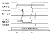
かくして上述した如く構成された無停電電源装置によれば、図2および図3にその動作タイミングをそれぞれ示すように、タイミングt1において外部電源入力(商用電源)が途絶えると、或いは電源スイッチがオフされると、これを検出して電源遮断信号が発せられる。これと同時に二次電池3から電子機器1への電力供給が開始され、電子機器1の動作がバックアップされる。そしてこの電源遮断信号が出力されてから一定時間(例えば3分)後のタイミングt2においてシャットダウン信号が発せられ、これを受けて出力制御用スイッチ11が遮断されて二次電池3から電子機器1へのバックアップ電源の供給が停止される。
Thus, according to the uninterruptible power supply configured as described above, as shown in FIG. 2 and FIG. 3, respectively, the operation timing is cut off at the timing t1, or the power switch is turned off. Then, this is detected and a power cutoff signal is issued. At the same time, power supply from the
しかる後、外部電源入力(商用電源)が復旧することなくタイマー回路18によって所定時間が計時されると(タイミングt3)、図2に示すようにタイマー出力(内部動作停止信号)が発せられて制御回路10における内部電源Vcの出力が停止し、タイミングt3以降における制御回路10の動作が停止する。その後、タイミングt4において外部電源入力(商用電源)が復旧すると、これを受けて電子機器1への電力供給が開始され、二次電池3への充電も再開される。
Thereafter, when a predetermined time is counted by the
この場合、タイミングt3〜t4の期間に亘って制御回路10への電源供給が停止していたので、それまでに電池状態監視回路15が取得していた二次電池3の充電状態や電池状態に関する情報は消失している。そして制御回路10は、タイミングt4において再起動されることになるので、その初期動作として二次電池3の残容量等の電池状態を検出する処理を実行し、新たに検出した情報に基づいて二次電池3に対する充電制御を実行する。具体的には二次電池3の残容量の情報は、二次電池3の電圧を測定すれば、この電圧より概算の残容量を得ることができる。またこの電池電圧と電池温度とを測定し、予め得られている電池電圧と電池温度との関係より、概算の残容量を得ることもできる。そして、その後の充電により二次電池3が満充電となったとき、その残容量を100%とすれば良い。
In this case, since the power supply to the
これに対して図3に示すようにタイマー回路18によって所定時間が計時される以前に(タイミングt5)外部電源入力(商用電源)が復旧した場合、或いは電源スイッチが逗留された場合には、これによって電子機器1への電力供給が再開されてタイマー回路18がリセットされる。この結果、タイマー出力(内部動作停止信号)が発せられることがなく、制御回路10は継続的に内部電源Vcの供給を受けて動作する。即ち、制御回路10が動作停止することはなく、前述した如く検出された二次電池3の電池状態や充電状態を示す情報がそのまま保存される。そして外部電源入力(商用電源)が復旧したタイミングt5において、制御回路10は保存していた二次電池3の電池状態や充電状態を示す情報に従って該二次電池3に対する充電制御を再開する。この場合、二次電池3の電池温度等に基づいて自己放電等による残容量を補正した上で、充電制御を再開することも勿論可能である。従って今まで検出していた二次電池3の電池状態や充電状態を示す情報をそのまま活用して該二次電池3の充電を制御することが可能となる。
On the other hand, as shown in FIG. 3, when the external power input (commercial power) is restored before the predetermined time is counted by the timer circuit 18 (timing t5), or when the power switch is detained, As a result, the power supply to the
かくして上述した無停電電源装置によれば、EEPROM等の不揮発性記憶装置を用いることなく、簡易に、しかも効果的に二次電池3の充電を制御することができ、また電子機器1および無停電電源装置を長期間に亘って停止させる場合や、停電状態が長期間に及ぶような場合には、制御回路10での無駄な電力消費を効果的に抑えることができる。また停電時間等に応じて二次電池3の残容量を予測する必要もなく、停電(休止)期間が長い場合には、改めて二次電池3の電池状態や充電状態を検出し直すので、信頼性の乏しい過去のデータに左右されることなく、その充電制御を的確に実行することができる等の効果が奏せられる。
Thus, according to the uninterruptible power supply described above, the charging of the
尚、上述の(c)の場合のように、電子機器1を手動でオフにし、手動スイッチAをオフするときは、電源遮断検出回路4からの遮断信号がシャットダウン検出回路17に入力されると共に、制御回路10は、既に終了状態の電子機器1よりシャットダウン信号(またはこれに対応する信号)を得ているので、上述した(a)および(b)の場合と同様にスイッチ11を遮断する共にタイマー回路18による計時を開始させれば良い。この後の動作は、上述した(a)および(b)の場合と同様であるので、その説明は省略する。
When the
尚、本発明は上述した実施形態に限定されるものではない。上述した実施形態においては、タイマー回路18にて所定時間を計時した後には制御回路10の機能を停止させ、その後、停電が復旧したときや電源スイッチが投入されたとき、再度、二次電池3の電池状態を求め直すものとしている。この場合、二次電池3に十分なる残容量が残っていることもあるので、例えば電池電圧と残容量との関係を、その放電開始時の容量や温度に関係付けてテーブル化したり、或いは計算式として求めておき、復電時(停電復旧時)に求められる電池電圧Vからその残容量を求めて二次電池3の充電制御を行うようにしても良い。この場合、満充電が検出されたときの電池残容量を100%として設定しておけば、その後の残容量計算を正確に行うことが可能となる。
The present invention is not limited to the embodiment described above. In the above-described embodiment, the function of the
また実施形態においてはシャントダウン信号を受けてタイマー回路18をスタートさせたが、電源遮断信号の発生タイミングを基準としてタイマー回路18をスタートさせるように構成することも可能である。更には前述した各種のアラーム情報については、停電発生時やシャントダウン信号発生時、或いはタイマー回路18による制御回路10の動作停止直前等に不揮発性記憶装置に書き込み、これを履歴として保存するようにすることも有用である。また電子機器1のバックアップ動作に要する時間を見込んで、前述したシャントダウン信号を制御回路10において内部的に発生させるようにしても良い。その他、本発明はその要旨を逸脱しない範囲で種々変形して実施することができる。
In the embodiment, the
1 電子機器(コンピュータ)
2 電源回路
3 二次電池
4 電源遮断検出回路
5 充電制御用スイッチ素子
10 制御回路
11 出力制御用スイッチ
12 電源制御部
13 内部電源スイッチ
14 内部電源回路
15 電池状態監視部
16 充電制御部
17 シャットダウン検出回路
18 タイマー回路
1 Electronic equipment (computer)
DESCRIPTION OF
Claims (3)
前記外部電源入力から得られる電力エネルギを蓄えると共に、前記電源回路への前記外部電源入力が途絶えたときで前記電子機器が駆動状態のとき該電源回路に代わって前記電子機器に電力を供給する二次電池と、
前記外部電源入力から得られる電力、または前記二次電池から得られる電力を受けて動作して該二次電池に対する充電を制御すると共に、前記二次電池から前記電子機器への電力供給を制御する制御手段と、
前記電源回路への前記外部電源入力が途絶えたとき前記電子機器と前記制御手段の一方または両方に対して電源遮断信号を出力する電源遮断検出部と、
前記電源遮断信号の発生タイミングから一定時間後、または前記電子機器からシャットダウン信号が与えられてから一定時間後に前記制御手段への電力供給を停止させるタイマー手段とを具備し、
前記制御手段は、前記一定時間内であれば前記二次電池の状態としての残容量を記憶し、前記一定時間の経過後であれば信頼性が乏しいとして前記二次電池の状態としての残容量を記憶しないと共に、
前記電源遮断信号の発生後、前記一定時間内に前記外部電源入力が再度加えられた際、記憶した前記二次電池の状態としての残容量の情報に従って前記二次電池に対する充電制御を再開し、前記電源遮断信号の発生後から一定時間経過後に前記外部電源入力が再度加えられた際、前記二次電池の状態としての残容量を検出し直して該二次電池に対する充電制御を開始するものであることを特徴とする無停電電源装置。 A power supply circuit that receives external power input and supplies power to a predetermined electronic device;
Storing power energy obtained from the external power input and supplying power to the electronic device instead of the power circuit when the external power input to the power circuit is interrupted and the electronic device is in a driving state; Next battery,
Operates in response to power obtained from the external power supply input or power obtained from the secondary battery to control charging of the secondary battery and control power supply from the secondary battery to the electronic device Control means;
A power-off detector that outputs a power-off signal to one or both of the electronic device and the control means when the external power input to the power circuit is interrupted;
Timer means for stopping the power supply to the control means after a certain time from the generation timing of the power-off signal or after a certain time since the shutdown signal was given from the electronic device,
The control means stores the remaining capacity as the state of the secondary battery within the predetermined time, and the remaining capacity as the state of the secondary battery as having low reliability after the lapse of the predetermined time. Is not remembered ,
When the external power input is reapplied within the predetermined time after the generation of the power shutoff signal, the charging control for the secondary battery is resumed according to the stored information on the remaining capacity as the state of the secondary battery, When the external power input is applied again after a lapse of a certain time from the occurrence of the power shutoff signal, the remaining capacity as the state of the secondary battery is detected again and charging control for the secondary battery is started. uninterruptible power supply, characterized in that there.
Priority Applications (3)
| Application Number | Priority Date | Filing Date | Title |
|---|---|---|---|
| JP2003282088A JP4111890B2 (en) | 2003-07-29 | 2003-07-29 | Uninterruptible power system |
| CNB2004100492159A CN100358216C (en) | 2003-07-29 | 2004-06-02 | Uninterruptible power supply device |
| US10/893,354 US7026726B2 (en) | 2003-07-29 | 2004-07-19 | Uninterruptible power supply device |
Applications Claiming Priority (1)
| Application Number | Priority Date | Filing Date | Title |
|---|---|---|---|
| JP2003282088A JP4111890B2 (en) | 2003-07-29 | 2003-07-29 | Uninterruptible power system |
Publications (3)
| Publication Number | Publication Date |
|---|---|
| JP2005051935A JP2005051935A (en) | 2005-02-24 |
| JP2005051935A5 JP2005051935A5 (en) | 2006-06-01 |
| JP4111890B2 true JP4111890B2 (en) | 2008-07-02 |
Family
ID=34100987
Family Applications (1)
| Application Number | Title | Priority Date | Filing Date |
|---|---|---|---|
| JP2003282088A Expired - Fee Related JP4111890B2 (en) | 2003-07-29 | 2003-07-29 | Uninterruptible power system |
Country Status (3)
| Country | Link |
|---|---|
| US (1) | US7026726B2 (en) |
| JP (1) | JP4111890B2 (en) |
| CN (1) | CN100358216C (en) |
Families Citing this family (22)
| Publication number | Priority date | Publication date | Assignee | Title |
|---|---|---|---|---|
| JP4626369B2 (en) * | 2005-04-06 | 2011-02-09 | Tdkラムダ株式会社 | Battery unit |
| JP2008092768A (en) * | 2006-10-05 | 2008-04-17 | Nippon Telegr & Teleph Corp <Ntt> | Discharger, method and program for controlling discharge, and program recording medium |
| JP4750747B2 (en) * | 2007-04-09 | 2011-08-17 | キヤノン株式会社 | Storage device, storage device control method, and control device |
| TWI389422B (en) * | 2008-10-16 | 2013-03-11 | Delta Electronics Inc | Auto-start circuit and uninterruptible power supply using the same |
| JP5397985B2 (en) * | 2008-11-26 | 2014-01-22 | Necエナジーデバイス株式会社 | Secondary battery pack |
| WO2010082608A1 (en) | 2009-01-14 | 2010-07-22 | ミツミ電機株式会社 | Protecting monitor circuit, battery pack, secondary battery monitor circuit and protecting circuit |
| JP5460167B2 (en) * | 2009-07-31 | 2014-04-02 | キヤノン株式会社 | Information processing apparatus, control method for information processing apparatus, and control program |
| TWI415366B (en) * | 2009-12-29 | 2013-11-11 | Delta Electronics Inc | Dc uninterruptible power supply circuit having combined charging and discharging circuit |
| US9625529B2 (en) | 2011-11-11 | 2017-04-18 | Stmicroelectronics, Inc. | Battery pack management |
| US20130158726A1 (en) | 2011-12-20 | 2013-06-20 | Kohler Co. | System and method for using a network to control multiple power management systems |
| US9281716B2 (en) * | 2011-12-20 | 2016-03-08 | Kohler Co. | Generator controller configured for preventing automatic transfer switch from supplying power to the selected load |
| JP6021480B2 (en) * | 2012-07-10 | 2016-11-09 | キヤノン株式会社 | Printing device |
| WO2014027462A1 (en) * | 2012-08-13 | 2014-02-20 | 京セラ株式会社 | Energy management device, and energy-management-device control method |
| US20160134147A1 (en) * | 2013-06-13 | 2016-05-12 | Firebright1 Green Energy(Shanghai) Limited. | Battery Energy Storage System and Controlling Method |
| JP6326745B2 (en) * | 2013-09-05 | 2018-05-23 | 富士通株式会社 | Battery control device, battery charge capacity diagnosis method, and battery charge capacity diagnosis program |
| CN104620457B (en) * | 2013-09-11 | 2017-09-26 | 株式会社东芝 | Power storage controller |
| WO2016103379A1 (en) | 2014-12-25 | 2016-06-30 | 東芝三菱電機産業システム株式会社 | Uninterruptible power supply device |
| US10931139B1 (en) | 2015-12-29 | 2021-02-23 | Signify Holding B.V. | Emergency battery packs for low voltage systems |
| US10424963B1 (en) * | 2016-02-18 | 2019-09-24 | Eaton Intelligent Power Limited | Methods and systems for charging a backup battery pack |
| DE102018203763A1 (en) * | 2018-03-13 | 2019-09-19 | Homag Gmbh | Device and method for uninterruptible power supply |
| CN112514201A (en) * | 2019-05-30 | 2021-03-16 | 东芝三菱电机产业系统株式会社 | Uninterruptible power supply device |
| US11822403B1 (en) | 2022-06-14 | 2023-11-21 | Schneider Electric It Corporation | Systems and methods for intelligent UPS shutdown sequencing in virtualization environments |
Family Cites Families (8)
| Publication number | Priority date | Publication date | Assignee | Title |
|---|---|---|---|---|
| US5302858A (en) * | 1991-12-11 | 1994-04-12 | Best Power Technology, Incorporated | Method and apparatus for providing battery charging in a backup power system |
| CN2164069Y (en) * | 1993-04-03 | 1994-05-04 | 明风电子企业股份有限公司 | Intelligent non-intermittent power supply |
| JP3697818B2 (en) * | 1996-02-28 | 2005-09-21 | 新神戸電機株式会社 | Storage battery deterioration diagnosis method and apparatus, and AC uninterruptible power supply |
| JP3213910B2 (en) * | 1997-08-13 | 2001-10-02 | 富士電機システムズ株式会社 | Battery diagnostic device |
| JP2002027683A (en) | 2000-07-05 | 2002-01-25 | Toshiba Battery Co Ltd | Electronic equipment |
| US6784641B2 (en) * | 2000-09-20 | 2004-08-31 | Toshiba Battery Co., Ltd. | Uninterruptible power supply |
| JP2002258993A (en) | 2001-03-05 | 2002-09-13 | Toshiba Tec Corp | Uninterruptible power supply unit |
| US6639386B2 (en) * | 2001-11-02 | 2003-10-28 | Sanyo Electric Co., Ltd. | Rechargeable battery device equipped with life determination function |
-
2003
- 2003-07-29 JP JP2003282088A patent/JP4111890B2/en not_active Expired - Fee Related
-
2004
- 2004-06-02 CN CNB2004100492159A patent/CN100358216C/en not_active Expired - Fee Related
- 2004-07-19 US US10/893,354 patent/US7026726B2/en not_active Expired - Fee Related
Also Published As
| Publication number | Publication date |
|---|---|
| JP2005051935A (en) | 2005-02-24 |
| CN100358216C (en) | 2007-12-26 |
| US20050024905A1 (en) | 2005-02-03 |
| CN1578057A (en) | 2005-02-09 |
| US7026726B2 (en) | 2006-04-11 |
Similar Documents
| Publication | Publication Date | Title |
|---|---|---|
| JP4111890B2 (en) | Uninterruptible power system | |
| JP2007215309A (en) | Battery pack control method | |
| JPH0416806B2 (en) | ||
| JPH11289102A (en) | Power controller for solar generator system | |
| JP2006203978A (en) | Uninterruptible power system | |
| KR20150129517A (en) | Electronic Device with memory data backup function | |
| JP2010218743A (en) | Battery pack | |
| JP2009195036A (en) | Control method of pack battery | |
| JP4435000B2 (en) | Battery control circuit, electronic device equipped with the battery control circuit, charge control program, and charge control method | |
| JP4682725B2 (en) | Portable information terminal | |
| JP6019678B2 (en) | Mobile terminal device | |
| JP4275107B2 (en) | Solar power generation device and charge control device | |
| JP2018142392A (en) | Memory power supply circuit, control device, and memory power supply method | |
| CN110912219B (en) | Charging protection circuit, charging device, electronic equipment and charging protection method | |
| JP5176720B2 (en) | Equipment control device and cogeneration system | |
| JPH03148719A (en) | Power supply without power failure | |
| JPH11144455A (en) | Memory backup control apparatus and method | |
| JP3546737B2 (en) | Charger | |
| JP3087650B2 (en) | Automatic power recovery method | |
| JP3807308B2 (en) | Data backup system and method | |
| JP3396417B2 (en) | Backup device | |
| JPH04248608A (en) | Programmable controller | |
| KR20230004517A (en) | Electrical system for aerosol generating device | |
| EA042603B1 (en) | ELECTRICAL SYSTEM FOR AEROSOL GENERATING DEVICE | |
| JP2773367B2 (en) | Electronic equipment |
Legal Events
| Date | Code | Title | Description |
|---|---|---|---|
| A521 | Written amendment |
Free format text: JAPANESE INTERMEDIATE CODE: A523 Effective date: 20060405 |
|
| A621 | Written request for application examination |
Free format text: JAPANESE INTERMEDIATE CODE: A621 Effective date: 20060405 |
|
| A131 | Notification of reasons for refusal |
Free format text: JAPANESE INTERMEDIATE CODE: A131 Effective date: 20070912 |
|
| A521 | Written amendment |
Free format text: JAPANESE INTERMEDIATE CODE: A523 Effective date: 20071101 |
|
| A131 | Notification of reasons for refusal |
Free format text: JAPANESE INTERMEDIATE CODE: A131 Effective date: 20071205 |
|
| A521 | Written amendment |
Free format text: JAPANESE INTERMEDIATE CODE: A523 Effective date: 20080128 |
|
| TRDD | Decision of grant or rejection written | ||
| A01 | Written decision to grant a patent or to grant a registration (utility model) |
Free format text: JAPANESE INTERMEDIATE CODE: A01 Effective date: 20080312 |
|
| A61 | First payment of annual fees (during grant procedure) |
Free format text: JAPANESE INTERMEDIATE CODE: A61 Effective date: 20080408 |
|
| FPAY | Renewal fee payment (event date is renewal date of database) |
Free format text: PAYMENT UNTIL: 20110418 Year of fee payment: 3 |
|
| FPAY | Renewal fee payment (event date is renewal date of database) |
Free format text: PAYMENT UNTIL: 20120418 Year of fee payment: 4 |
|
| FPAY | Renewal fee payment (event date is renewal date of database) |
Free format text: PAYMENT UNTIL: 20130418 Year of fee payment: 5 |
|
| FPAY | Renewal fee payment (event date is renewal date of database) |
Free format text: PAYMENT UNTIL: 20140418 Year of fee payment: 6 |
|
| LAPS | Cancellation because of no payment of annual fees |