JP4110084B2 - Image forming apparatus, control method therefor, and image forming method - Google Patents
Image forming apparatus, control method therefor, and image forming method Download PDFInfo
- Publication number
- JP4110084B2 JP4110084B2 JP2003408821A JP2003408821A JP4110084B2 JP 4110084 B2 JP4110084 B2 JP 4110084B2 JP 2003408821 A JP2003408821 A JP 2003408821A JP 2003408821 A JP2003408821 A JP 2003408821A JP 4110084 B2 JP4110084 B2 JP 4110084B2
- Authority
- JP
- Japan
- Prior art keywords
- image
- unit
- image forming
- print data
- forming apparatus
- Prior art date
- Legal status (The legal status is an assumption and is not a legal conclusion. Google has not performed a legal analysis and makes no representation as to the accuracy of the status listed.)
- Expired - Fee Related
Links
Images


Description
本発明は、LAN等のネットワークに接続される画像形成装置に関するものである。 The present invention relates to an image forming apparatus connected to a network such as a LAN.
近年、画像形成装置においては機能の複合化が進み、複写機能、プリンタ機能、ファクシミリ機能等が1台の装置で実現されており、その上、このような画像形成装置はネットワークに接続されることもあり、ネットワーク上のパソコン、ワークステーション用のプリンタ、スキャナとして利用されるようになっている。 In recent years, image forming apparatuses have become more complex in function, and a copying function, a printer function, a facsimile function, and the like are realized by a single apparatus. In addition, such an image forming apparatus is connected to a network. It is also used as a networked personal computer, workstation printer, and scanner.
ネットワークを介して送られてくる画像データ、電話回線を介して送られるファクシミリ画像データは、前記画像形成装置のファイルに一旦格納された後、複写動作の合間を縫って画像形成されて排出される。 Image data sent via a network and facsimile image data sent via a telephone line are temporarily stored in a file of the image forming apparatus, and then are formed and ejected after copying operations. .
また、例えばプリンタ装置に外部インタフェイスを介してコンピュータを接続し、コンピュータで作成した文書データ等を入力し、記録紙に可視画像としてプリントアウトするものが知られている。この場合、コンピュータ側ではプリント指示を行うと共に、画像データをプリンタ装置に送り、プリント指示を受けたプリンタ装置はこの送られてきた画像データに基づく画像を順次記録紙に記録出力するものである。 In addition, for example, a printer is connected to a printer via an external interface, and document data created by the computer is input and printed out as a visible image on recording paper. In this case, the computer side issues a print instruction and sends image data to the printer apparatus. The printer apparatus which receives the print instruction sequentially records and outputs images based on the sent image data on a recording sheet.
しかしながら、上述のような画像形成装置を中心としたシステムでは、次のような問題点があった。 However, the system centering on the image forming apparatus as described above has the following problems.
すなわち、ネットワーク上の端末から画像形成装置に対して、例えばコンピュータからプリンタ機能を有する複写機に対して画像データを転送したときに、第3者が複写作業を行っている場合は、その作業が優先されるため、一連の複写作業が終了するまで出力されない。このため、画像形成装置に複写作業を待つ列ができている場合や、大量の複写を行っている場合等は、転送した画像データが何時出力されるのかがわからないという問題点があった。 That is, when image data is transferred from a terminal on the network to the image forming apparatus, for example, from a computer to a copying machine having a printer function, if the third person is performing a copying operation, the operation is performed. Since priority is given, it is not output until a series of copying operations are completed. For this reason, there is a problem in that it is not possible to know when the transferred image data is output when the image forming apparatus has a line waiting for a copying operation or when a large amount of copying is performed.
また、複合機能を有する画像形成装置の出力用排紙トレイが単一である場合、その排出トレイには、各種の出力紙が時を選ばず出力され、機能別の仕分け、シート束間の仕分けがなされないまま出力紙が放置されることがあった。トレイが単一でなく、プリント機能やFAX機能、コピー機能など画像形成装置の各機能に対応する排出トレイが設けられていたとしても、ある機能の排紙トレイに着目してみれば、別々に出力されたシート束とシート束を仕切る手段はなく画像形成装置からの出力紙は、ただ漫然と排紙トレイに積み重ねられているのみであり、どれが所望のシート束であるか判別できなかった。 In addition, when the output tray of the image forming apparatus having a composite function is a single output tray, various output sheets are output to the discharge tray at any time. In some cases, the output paper was left unattended. Even if there is a single tray and a discharge tray corresponding to each function of the image forming apparatus such as the print function, FAX function, copy function, etc. There is no means for separating the output sheet bundle from the sheet bundle, and the output sheets from the image forming apparatus are merely stacked on the discharge tray indiscriminately, and it is impossible to determine which is the desired sheet bundle.
従って、シート束を取り出す際は、一度に全部のシート束を取り出して、その中から所望の束を探し出し、残りの束は元の排紙トレイに戻すという作業を余儀なくされた。このような状況下では、出力されたドキュメントの一部、または、全部を紛失してしまうという不測の事態が発生することもあった。 Therefore, when taking out the sheet bundle, it is necessary to take out all the sheet bundles at once, search for a desired bundle from the bundle, and return the remaining bundle to the original paper discharge tray. Under such circumstances, an unexpected situation may occur in which a part or all of the output document is lost.
さらにまた、前記プリンタ装置に外部インタフェイスを介してコンピュータを接続する場合、機密文書を出力させようとした際に、コンピュータとプリンタ装置とが離れた位置に設置されていた場合等には、使用者が出力させた用紙をプリンタ装置のところまで取りに行くまでの間に、他人に見られてしまう可能性があり、機密保持上の問題点があった。 Furthermore, when a computer is connected to the printer device via an external interface, it is used if the computer and the printer device are installed at a distance when attempting to output a confidential document. There is a possibility of being seen by others before the paper output by the person goes to the printer device, and there is a problem of confidentiality.
本発明は、このような状況のもとでなされたもので、画像形成装置からの印刷データを特定するための情報の入力により印刷を開始させることができ、しかも、印刷データは画像形成装置に記憶されたもの、或いはネットワークを介して接続されたファイルサーバに記憶されたものを選択することが可能となる画像形成装置を提供することを課題とするものである。 The present invention has been made under such circumstances, and printing can be started by inputting information for specifying print data from the image forming apparatus, and the print data is sent to the image forming apparatus. It is an object of the present invention to provide an image forming apparatus capable of selecting a stored one or one stored in a file server connected via a network.
上記課題を解決するため、本発明では、画像形成装置を次の(1)のとおりに、画像形成装置の制御方法を次の(2)のとおりに、画像形成方法を次の(3)のとおりに構成する。
(1)印刷データを生成する端末とネットワークを介して接続された画像形成装置であって、
前記端末より、少なくともユーザを特定するためのユーザID、及び前記端末において生成された印刷データを特定するための識別子を含む、情報を受信する受信手段と、
前記受信手段が受信した前記ユーザIDと前記識別子とをそれぞれ対応付けて管理する管理手段と、
前記印刷データを取得するために、前記ユーザIDを入力する入力手段と、
前記ネットワーク上の端末に格納されている印刷データの中から、前記入力手段から入力されたユーザIDに対応付けて管理されている識別子に基づいて選択された前記印刷データを、前記ネットワークを介して取得する取得手段と、
前記取得手段が取得した印刷データに基づき出力用紙上に画像を印刷する印刷手段とを有する画像形成装置。
(2)印刷データを生成する端末とネットワークを介して接続された画像形成装置の制御方法であって、
前記端末より、少なくともユーザを特定するためのユーザID、及び前記端末において生成された印刷データを特定するための識別子を含む、情報を受信する受信工程と、
前記受信工程で受信した前記ユーザIDと前記識別子とを対応付けて管理する管理工程と、
前記印刷データを取得するために、前記ユーザIDを入力する入力工程と、
前記ネットワーク上の端末に格納されている印刷データの中から、前記入力工程で入力されたユーザIDに対応付けて管理された識別子に基づいて選択された前記印刷データを、前記ネットワークを介して取得する取得工程と、
前記取得工程で取得した印刷データに基づき出力用紙上に画像を印刷する印刷工程と、
を有する画像形成装置の制御方法。
(3)印刷データを生成する端末、印刷データを保持するファイルサーバ、及び印刷データに基づき出力用紙上に画像を印刷する画像形成装置が、互いにネットワークを介して接続された画像形成システムにおける画像形成方法であって、
前記画像形成装置において、
前記端末より、少なくともユーザを特定するためのユーザID、及び前記ファイルサーバに保持されている印刷データを特定するための識別子を含むコマンドを受信し、
前記受信したユーザIDと識別子とをそれぞれ対応付けて管理し、
前記印刷データを取得するために前記ユーザIDを入力し、
前記ファイルサーバに保持されている印刷データの中から、前記入力されたユーザIDに対応付けて管理されている識別子に基づいて選択された前記印刷データを、前記ファイルサーバから取り込み、
前記取り込んだ印刷データに基づき出力用紙上に画像を印刷する画像形成方法。
In order to solve the above-mentioned problems, in the present invention, the image forming apparatus is as described in (1) below, the control method of the image forming apparatus is as described in (2), and the image forming method is as described in (3) below. Configure as follows.
(1) An image forming apparatus connected via a network to a terminal that generates print data,
Receiving means for receiving information including at least a user ID for identifying a user and an identifier for identifying print data generated in the terminal from the terminal;
Managing means for managing the user ID and the identifier received by the receiving means in association with each other;
Input means for inputting the user ID to obtain the print data;
The print data selected based on the identifier managed in association with the user ID input from the input means from the print data stored in the terminal on the network is transmitted via the network. Acquisition means for acquiring
An image forming apparatus comprising: a printing unit that prints an image on output paper based on the print data acquired by the acquisition unit.
(2) A method for controlling an image forming apparatus connected to a terminal that generates print data via a network,
A receiving step of receiving information from the terminal, including at least a user ID for identifying the user and an identifier for identifying the print data generated in the terminal;
A management step of managing the user ID and the identifier received in the reception step in association with each other;
An input step of inputting the user ID to obtain the print data;
The print data selected based on the identifier managed in association with the user ID input in the input step from the print data stored in the terminal on the network is transmitted via the network. An acquisition process to acquire;
A printing step of printing an image on output paper based on the print data acquired in the acquisition step;
A method for controlling an image forming apparatus.
(3) Image formation in an image forming system in which a terminal that generates print data, a file server that holds print data, and an image forming apparatus that prints an image on output paper based on the print data are connected to each other via a network A method,
In the image forming apparatus,
A command including at least a user ID for specifying a user and an identifier for specifying print data held in the file server is received from the terminal,
Managing the received user ID and identifier in association with each other;
Enter the user ID to obtain the print data,
The print data selected based on the identifier managed in association with the input user ID from the print data held in the file server is fetched from the file server,
An image forming method for printing an image on output paper based on the captured print data.
本発明によれば、画像形成装置がネットワークを介して、少なくともユーザを特定するためのユーザID、及びネットワーク上の端末で生成された印刷データを特定するための識別子を受信するとともに、当該ユーザID及び識別子をそれぞれ対応づけて管理しておき、画像形成装置においてユーザIDが入力された場合に、ネットワーク上の端末に格納されている印刷データの中から、前記入力されたユーザIDに対応付けて管理された識別子に基づいて選択された印刷データを、ネットワークを介して取得して出力することができる。 According to the present invention, the image forming apparatus receives at least a user ID for specifying a user and an identifier for specifying print data generated by a terminal on the network via the network, and the user ID and aft managed in association respectively identifier, if the user ID is inputted in the image forming apparatus, from among the print data stored in the terminal on the network, associating to the input user ID the print data selected based on the identifier supervises as can be output obtained via the network.
以下本発明を実施するための最良の形態を、実施例により詳しく説明する。 Hereinafter, the best mode for carrying out the present invention will be described in detail with reference to examples.
図1に、本発明の画像形成システムの一実施形態例に係る電子写真方式の画像形成装置の構成ブロック図、図2に、図1この画像形成装置の構成縦断側面図を示す。図1及び図2に示すように、本実施例の画像形成装置は、画像入力装置(以下、リーダ部と記す)1、画像出力部(以下、プリンタ部と記す)2、画像入出力制御部(外部装置)3、循環式自動原稿搬送装置4、用紙(シート)後処理装置5を主要構成要素としており、リーダ部1とプリンタ部2とにより、本体部が構成されている。
FIG. 1 is a block diagram showing a configuration of an electrophotographic image forming apparatus according to an embodiment of the image forming system of the present invention. FIG. 2 is a longitudinal sectional side view showing the configuration of the image forming apparatus shown in FIG. As shown in FIGS. 1 and 2, an image forming apparatus according to this embodiment includes an image input device (hereinafter referred to as a reader unit) 1, an image output unit (hereinafter referred to as a printer unit) 2, an image input / output control unit. (External device) 3, circulation type
(本体(リーダ部1とプリンタ部2)構成説明)
図1及び図2におけるリーダ部1は、原稿を画像データに変換するもので、原稿載置台(プラテンガラス)101、ランプ102とミラー103とを有するスキャナユニット104、ミラー105、ミラー106、レンズ107、CCD等の光電変換素子を有するイメージ・センサ部(以下、CCDと記す)108等を有している。
(Description of configuration of main body (
The reader unit 1 in FIGS. 1 and 2 converts a document into image data, and a
プリンタ部2は、プリント命令により画像データをシート上に可視像として出力する画像形成手段であり、露光制御部201、感光体(ドラム)202、現像器203、複数種類の記録紙(以下、シートと記す)の各カセット204、205、転写部206、定着部207、排紙部208、搬送方向切り替え部材209、再給紙用シート積載部210及び搬送ローラ211を有している。
The
(本体(リーダ部1とプリンタ部2)動作説明)
図1、2を参照しながらリーダ部1、プリンタ部2の構成及び動作について説明する:
まず、リーダ部1においては、循環式自動原稿送り装置4上に積載された原稿は、1枚づつ順次プラテンガラス面101上に搬送される(循環式自動原稿送り装置4の構成及び動作説明は後述する)。原稿が、ガラス面101の所定位置へ搬送されると、スキャナ部のランプ102が点灯し、かつスキャナユニット104が移動して原稿を照射する。原稿の反射光は、各ミラー103、105、106、レンズ107を介してCCDイメージ・センサ部108に入力される。そして、CCD108に照射された原稿の反射光は、ここで光電変換等の電気的処理が行われ、通常のデジタル処理が施される。この後、これらの信号はプリンタ部2に入力される。
(Description of operation of main unit (
The configuration and operation of the
First, in the
次にプリンタ部2においては、プリンタ部2に入力された画像信号が、レーザドライバ212により発光されたレーザ発光部の露光制御部201にて変調された光信号に変換されて感光体ドラム202を照射する。照射光によって感光体ドラム202上に作られた潜像は、現像器203によって現像される。上記現像像の先端とタイミングを併せてシートカセット204もしくは205よりシートが搬送され、転写部206において、上記現像された像がシートに転写される。転写された像は定着部207にてシートに定着された後、排紙部208より装置外部に排出される。そして、排紙部208から出力されたシートは、シート後処理装置5(シート後処理装置5の構成及び動作は後述する)で、予め指定された動作モードに応じて、仕分け、綴じ等が行われる。
Next, in the
続いて、順次読み込む画像を1枚の出力用紙の両面に出力する方法について説明する:
定着部207で定着されたシートを、一度、排紙部208まで搬送後、シートの搬送向きを反転して搬送方向切り替え部材(フラッパ)209を介して再給紙用シート積載部210に搬送する。そして、次の原稿が準備されると、上記プロセスと同様にして原稿画像が読み取られるが、シートについては再給紙用シート積載部210より給紙されるので、結局、同一出力紙の表面、裏面に2枚分の原稿画像を出力することができる。
Next, a method for outputting sequentially read images on both sides of one output sheet will be described:
After the sheet fixed by the fixing
(画像入出力制御装置3構成説明)
図1、2における画像入出力制御装置3は、各種の機能を有するもので、リーダ部1とケーブルを介して電気的に接続されている。図1において、画像入出力制御装置3は、ファクシミリ送受信を行うファクシミリ部301、このファクシミリ部301と接続されているハードディスク302、各種の原稿情報を電気信号に変換して光磁気ディスク等の外部記録装置303に保存するファイル部304、ネットワークを介してコンピュータと接続するためのネットワークインタフェイス部305、コンピュータからのコード情報をイメージ情報に展開することにより、画像情報を可視像とするためのフォーマッタ部306、リーダ部1からの情報を蓄積したり、コンピュータから送られてきた情報を一時的に蓄積するためのイメージメモリ部307、及び上記各機能を制御するコア部308等を備えている(不図示)。6は、LAN等のネットワークで、ネットワークインタフェイス部305と接続されている。
(Description of image input /
The image input /
(画像入出力制御装置3動作説明)
画像入出力制御装置3からプリンタ部2に入力された画像信号は、上記と同様に、定着部207にてシートに定着された後、このシートは、搬送方向切り替え部材209を介して再給紙用シート積載部210方向に搬送される。そして、このシートが搬送方向切り替え部材209を通り抜けた所で、搬送方向切り替え部材209を切り替えると同時に、搬送ローラ211を反転させることにより、このシートが排紙部208より装置外部に排出される。
(Description of image input /
The image signal input from the image input /
(循環式自動原稿送り装置4構成説明)
図3の構成縦断側面図で詳細に示すように、循環式自動原稿送り装置4には、原稿束を積載する原稿積載トレイ401を有し、この積載トレイ401には、原稿給送手段の一方の部分を構成する給送手段が装備されている。この給送手段は、半月ローラ402と、分離搬送ローラ403と、分離モータ(不図示)と、レジストローラ404と、全面ベルト405と、ベルト・モータ(不図示)と、搬送大ローラ406と、搬送モータ(不図示)と、排紙ローラ407と、フラッパ408と、リサイクルレバー409と、給紙センサ、反転センサ、排紙センサ(不図示)等から構成されている。
(Description of configuration of circulation type automatic document feeder 4)
As shown in detail in the longitudinal sectional side view of FIG. 3, the circulation type
(循環式自動原稿送り装置4動作説明)
前記半月ローラ402と分離搬送ローラ403とは、前記分離モータにより回転して、積載トレイ401上の原稿束の最下部から1枚ずつ分離するように構成されている。また、レジストローラ404と全面ベルト405とは、ベルト・モータにより回転して分離された原稿をシートパスa,bを介して原稿台ガラス101上の露光位置(シートパスc)まで搬送する。また、搬送大ローラ406は、搬送モータにより回転して原稿台ガラス101上の原稿をシートパスcからシートパスeに搬送する。このシートパスeに搬送された原稿は、排紙ローラ407により原稿を積載トレイ401の原稿束の最上部に戻される。
(Description of the operation of the circulating automatic document feeder 4)
The half-
また、リサイクルレバー409は、原稿の一循環を検知するもので、原稿給送開始時にリサイクルレバー409を原稿束の上部に載せ、原稿が順次給送され、最終原稿の後端がリサイクルレバー409を抜ける時に自重で落下することで原稿の一循環を検知する。
The
前記原稿給送手段では、両面原稿時に、原稿を一旦シートパスa,bからcに導き、次いで搬送大ローラ406を回転し、フラッパ408を切り替えることで原稿の先端をシートパスdに導き、次いでレジストローラ404によりシートパスbを通し、この後全面ベルト405で原稿を原稿台ガラス101上に搬送して停止することで原稿を反転させている。すなわち、原稿をシートパスc〜d〜bの経路で反転させている。なお、原稿束の原稿を1枚づつシートパスa〜b〜c〜d〜eを通して、リサイクルレバー409により一循環したことが検知されるまで搬送することによって、原稿の枚数をカウントすることができる。
In the document feeding means, when a double-sided document is used, the document is once guided from the sheet paths a and b to c, and then the transport
(シート後処理装置5の構成・動作説明)
シート後処理装置5は、図4にその構成縦断側面図、図5に構成斜視図をそれぞれ示すように、機体501、ビンユニット(排出手段)502及びステイプラ(綴じ手段)510から成り、この機体501は、搬入口503に近傍して搬入ローラ対504を備えている。搬入ローラ対504の下流には、搬送パス505あるいは506へシート搬送方向を切り替えるフラッパ507が配設されている。そして、一方の搬送パス506はほぼ水平方向に延びて、その下流に搬送ローラ対508が配設されており、また他方の搬送パス506は下方向に延びて、その下流に搬送ローラ対509が配設されており、さらにこのローラ対509の近傍位置にステイプラ510が配設されている。
(Description of configuration / operation of sheet post-processing device 5)
The sheet
搬入ローラ対504と搬送ローラ対508、509は搬送モータ(不図示)により駆動されている。上記搬送パス505には、シートの通過を検出するノンソートパスセンサ511が、そして搬送パス506にはソートパスセンサ512が配設されている。
The carry-in
ビンユニット502は、多数のビンB(B1〜Bn)を備えており、搬送ローラ対508及び509の下流側に配置されている。このビンユニット502のフックに一端を係合し、他端を機体501に固定したばねで重量を保持することにより、ビンユニット502は、昇降自在に支持されている。ビンユニット502の基端側の上下部には、各ガイドローラ513、514が回動自在に支持されており、これらのガイドローラ513、514は、各前記機体501に上下方向に延びるように設けられた案内溝515内を転動して前記ビンユニット502を案内するように構成されている。
The
また、機体501には、シフトモータ516が配設されている。機体501に枢支された回転軸517には、リードカム518が固定されている。前記シフトモータ516の出力軸には、チェーン519が張設されており、これによってシフトモータ516の回転はチェーン519を介して回転軸517へ伝達されるようになっている。
The
さらに、前記ビンユニット502は、傾斜部及び垂直部から成る底部フレーム520と、この底部フレーム520の先端手前側と奥側とに垂直に設けられた対をなすフレーム521、フレーム521によって支持されたカバー522により構成されるユニット本体523を有している。このユニット本体523の手前側には、シートに当接して整合することが可能な基準板が設けられている。底部フレーム520の基端奥側には、第1整合モータ(不図示)により回動する第1下アームが回動自在に支持されている。さらにカバー522の前記第1下アームと対向する位置に第1上アームが、前記第1下アームの支持軸と同軸を介して回動自在に支持されている。前記第1上アームの先端と前記第1下アームの先端には、第1整合棒524が架設されている。この整合棒524は第1整合モータにより回動するように構成されており、ビンB上のシートSを手前側に整合するようになっている。
Further, the
また同様に、上記底部フレーム520の基端手前側に、第2整合モータ(不図示)により回動する第2下アームが回動自在に支持されている。カバー522の前記第2下アームと対向する位置に第2上アームが、前記第2下アームの支持軸と同軸を介して回動自在に指示されている。前記第2下アームの先端と前記第2上アームの先端とには、整合棒525が架設されており、この整合棒525は、第2整合モータにより回動するように構成されておりビンB上のシートSを奥側に整合するようになっている。
Similarly, a second lower arm that is rotated by a second alignment motor (not shown) is rotatably supported on the near side of the base end of the
第1及び第2整合モータは、ステッピングモータであって、第1及び第2整合棒524、525の位置は、各ステッピングモータに与えるパルス数で正確に制御できる。また、第1及び第2整合棒524、525の位置は、整合棒ホームセンサにより検知される。第1及び第2整合棒524、525の位置は、前記整合棒ホームセンサと、前記第1及び第2整合モータに与えられるパルス数で制御できる。 The first and second alignment motors are stepping motors, and the positions of the first and second alignment bars 524 and 525 can be accurately controlled by the number of pulses applied to each stepping motor. The positions of the first and second alignment bars 524 and 525 are detected by the alignment bar home sensor. The positions of the first and second alignment bars 524 and 525 can be controlled by the number of pulses applied to the alignment bar home sensor and the first and second alignment motors.
前記ビンBは、先端手前及び奥にそれぞれ係合板が形成されており、この係合板が、フレーム521の内側に設けられた支持板と係合することにより、ビンBは先端側を支持されるようになっている。さらにビンBには、前記第1上、下アームの支持軸から所定距離離れた位置に第1整合棒524の回転距離より長くかつ第1整合棒524の幅よりも十分幅広な長孔526(図5)と、前記第2上、下アームの支持軸から所定距離離れた位置に第2整合棒525の回転距離より長く、かつ第2整合棒525の幅よりも十分幅広な長孔527(図5)が開設されている。ビンBの基端部Baは、シート収納面Bbに対して垂直に立ち上がっている。ビンBは、機体501に対して先端を上に所定角度傾斜しており、この傾斜によりシートは、シート収納面Bbを滑って後端を基端部Baに当接して前後方向を整合されるようになっている。
The bin B is formed with an engagement plate on the front side and the back side, and the engagement plate is engaged with a support plate provided inside the
また、ビンBには、ステイプラ510の進入する部分に切欠きが設けられており、ステイプラ510と干渉しないようになっている。そして、ビンB1、B2……Bnの長孔526には、第1整合棒524が嵌挿されており、この第1整合棒524は、長孔526内を回動して、ビンB上のシートを手前側に整合するよう構成されている。同様に、ビンB1、B2……の長孔527には前記整合棒525が嵌挿されており、この整合棒525は、長孔527内を回動して、ビンB上のシートを奥側に整合するよう構成されている。
Further, the bin B is provided with a notch at a portion where the
また、前記リードカム518は、ビンBの一部分と係合しており、リードカム518の回転により、ビンユニット502は、案内溝515に沿って昇降するように構成されている。なお、リードカム518の1回転は、リードカム529の近傍に配設されたリードカムセンサ528によって検出される。また、ビンユニット502の位置はビンホームポジションセンサ529によって検出される。ビンB上のシートの存在は、ソートトレイ紙有無検知センサ(シート後処理位置選択手段)530によって検出できる。
The
下部排紙ローラ対509の近傍には、ビンBに収納したシートを綴じ止め(ステイプル)処理する電動ステイプラ510がシートの搬入方向に直交する位置に駆動手段により進退可能に配設されており、通常ビンBの上下動の際に干渉しないように、第1位置イに退避しており、ビンB上のシートの束を綴じ止めする際に、前記駆動手段により第2位置ロにされて、シートの束を綴じ処理する。綴じ処理終了後、この電動ステイプラ510は、前記駆動手段により第1位置イに復帰移動する。
In the vicinity of the lower
また、電動ステイプラ510は、不図示のモータの回転によりステイプル動作を行い、複数のビンB1〜Bnのシートを綴じ止めする時に、1つのビンBのシートのステイプル動作終了後に、ビンユニット502が所定のビン位置に移動して、ビンBに収納したシートを綴じ止めするようになっている。また、前記駆動手段は図4に示された矢印R方向及び図5に示された矢印Y方向にステイプラ510を摺動移動、回転させることができる。
Further, the
ただし、シートが反転して排出された場合は、ステイプラ510は、前記駆動手段により上下反転され、また、後述する画像回転回路145(図8)で出力画像が回転された場合は、不図示のステイプラ位置検出手段の検出結果に応じて、前記駆動手段により、図5に示された矢印Y方向にスライドされた後、上記同様にステイプル動作を行う。
However, when the sheet is reversed and discharged, the
なお、図5において、531はマニュアルステイプルキーであって、ソート終了後にマニュアルステイプルキー531を押下された場合はステイプル動作を行う。また、第1整合棒524の回動動作により、ビン上のシート束の位置を手前に押し出すことが可能なようになっている。
In FIG. 5,
(操作部、表示部600の構成説明)
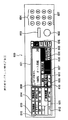
図6は、本体(リーダ部1とプリンタ部2)に設けた操作部115(後述図14)に含まれる操作・表示パネルの配置構成を示す正面図である。同図に示すように、この操作・表示パネル600の操作面には、後述する各種のキーと、液晶表示器等からなる表示部601とが設けられている。表示部601は、本装置の状態、コピー枚数、倍率、シート選択及び各種の操作に関する情報を表示するものである。この表示部はタッチパネル方式であり、各キーを押すことにより各種のモードを表示、選択可能となる。
(Description of configuration of operation unit and display unit 600)
FIG. 6 is a front view showing an arrangement configuration of operation / display panels included in an operation unit 115 (FIG. 14 described later) provided in the main body (
602は複写開始キー(コピースタートキー)であり、複写を開始する時に押す。603はクリア/ストップキーであり、待機(スタンバイ)中に押すとクリアキーの機能を有し、複写記録中はストップキーの機能を有する。このクリアキー/ストップキー603は、設定した複写枚数を解除する時に押す。604はテンキーであり、複写枚数を設定する時に押す。605は複写濃度キーであり、複写濃度を手動で調節する時に押す。606はAEキーであり、原稿の濃度に応じて、複写濃度を自動的に調節する時に、またはAE(自動濃度調節)を解除して濃度調節をマニュアル(手動)に切り替える時に押す。
607はカセット選択キーであり、図2に示す複数種類のシートカセット204、205等を選択する時に押す。また、原稿搬送装置4に原稿が載置されている時には、カセット選択キー607によりAPS(自動用紙選択)が選択できる。APSが選択された時には、出力すべき画像の大きさに応じた大きさの転写紙のカセットが自動選択される。
A
608は等倍キーであり、原稿の画像サイズと等倍(原寸)の複写をとる時に押す。609はズームキーであり、64〜142%の間で任意の倍率を指定する時に押す。610及び611は定形変倍キーであり、定形サイズの縮小・拡大を指定する時に押す。
また、612は、シート後処理装置5の動作モードを選択するキーであり、排紙方法(ステイプル、ソート、グループ)、記録後の用紙をステイプルで綴じることのできるステイプラ510がシート後処理装置5(図1)に接続されている場合は、ステイプルモード/ソートモード、記録済用紙の折り(断面Z形/断面V形)、の選択及び解除ができる。
さらに、613、614及び615は、各種の処理を設定するキーであり、例えば、両面モード、綴じ代設定、写真モード、多重処理、ページ連写、2in1モード等である。616は動作モードを選択するキー、617は、IDカードに記録されている読取りカードリーダである。また、620はID入力キーであり、ID入力キー620を押下することで、操作部115はID入力待ちモードになる。ID入力待ち状態でテンキー604からIDコードを入力し、入力が終了したらID入力キー620を再び押下することでIDコードを確定する。
Furthermore,
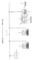
(ネットワークの説明)
図7は、本実施例形態における画像形成システムのネットワークの構成を示す図である。画像形成装置は、前記図1で示したように、原稿の画像を読み取るためのリーダ部1、入力された画像データを出力するためのプリンタ部2、ネットワーク制御機能を持つ画像入出力制御(外部)装置3、原稿を自動給紙してリーダ部1に読み込ませるための原稿搬送装置(フィーダ)4、プリンタ部2から排紙された用紙を複数あるビンの内の1つに格納するための用紙後処理装置(ソータ)5から構成されている。
(Network description)
FIG. 7 is a diagram illustrating a network configuration of the image forming system according to the present exemplary embodiment. As shown in FIG. 1, the image forming apparatus includes a
LAN6は複数の情報機器を接続し、任意の機器間でデータ交換を可能にするネットワークである。ワークステーション7、パソコン8は、ドキュメントの作成、修正、表示を行うもので、外部とのデータ交換のためにLAN6に接続されている。ファイルサーバ9はLAN6を経由して、画像入出力制御装置3、ワークステーション7、パソコン8などからアクセス可能な大容量記憶装置である。電話回線10は、画像入出力制御装置3に接続され、FAXのデータ送受信に使われる。また、リーダ部1、プリンタ部2、またはLAN6に接続された任意の機器が、遠隔地のネットワークにアクセスするためのものである。
The
(コア部308の構成・動作説明)
図8は、図1及び図2における画像入出力制御装置3のコア部308(図1)の詳細構成を示すブロック図であり、コア部308のコネクタ131は、リーダ部1のコネクタとケーブルで接続される。コネクタ131には、4種類の信号が内蔵されており、その第1の信号ライン187の信号は、8ビット多値のビデオ信号である。第2の信号ライン185の信号は、ビデオ信号を制御する制御信号、第3の信号ライン181の信号は、リーダ部1内のCPUと通信を行う。第4の信号ライン182の信号は、リーダ部1内のSUB・CPUと通信を行う信号である。信号181と信号182とは、通信用IC132で通信プロトコル処理された後、CPUバス183を介してCPU133に通信情報を伝達する。
(Description of configuration / operation of core unit 308)
FIG. 8 is a block diagram showing a detailed configuration of the core unit 308 (FIG. 1) of the image input /
信号187は、双方向のビデオ信号ラインであり、リーダ部1からの情報をコア部308で受け取ることや、コア部308からの情報をリーダ部1に出力することが可能である。信号187は、バッファ140に接続され、ここで双方向信号から片方向の信号188と170とに分離される。信号188は、リーダ部1からの8ビット多値のビデオ信号であり次段のLUT141に入力される。
The
このLUT141では、リーダ部1からの画像情報を、ルックアップテーブルにより所望する値に変換する。LUT141からの出力信号189は、2値化回路142及びセレクタ143に入力される。2値化回路142には、信号ライン189に出力された多値の信号を固定のスライスレベルで2値化する単純2値化機能、スライスレベルが注目画素の回りの画素の値から変動する変動スライスレベルによる2値化機能、及び誤差拡散法による2値化機能を有する。
The
2値化された情報は0の時OOH、1のときFFHの多値信号に変換され、次段のセレクタ143に入力される。セレクタ143は、LUT141からの信号か、または2値化回路142の出力信号かを選択する。セレクタ143は、LUT141からの信号か、または2値化回路142の出力信号かを選択する。セレクタ143からの出力信号190は、セレクタ144に入力される。セレクタ144は、ファクシミリ部301、ファイル部304、ネットワークインタフェイス部305、フォーマッタ部306、イメージメモリ部307からの出力ビデオ信号をそれぞれコネクタ135、136、137、138、139を介してコア部308に入力した信号194と、セレクタ143の出力信号190とをCPU133の指示により選択する。
The binarized information is converted into a multi-value signal of OOH when 0 and FFH when 1 and input to the
セレクタ144の出力信号191は、回転角度145、またはセレクタ146に入力される。回転回路145は、入力した画像信号を+90度、−90度、+180度に回転する機能を有する。回転回路145は、リーダ部1から出力された情報を2値化回路142で2値信号に変換された後、回転回路145にリーダ部1からの情報として記憶する。次にCPU133からの指示により回転回路145は、記憶した情報を回転して読み出す。
An
セレクタ146は、回転回路145の出力信号192と、回転回路145の入力信号191のいずれかを選択し、信号193として、ファクシミリ部301とのコネクタ135、ファイル部304とのコネクタ136、ネットワークインタフェイス部305とのコネクタ137、フォーマッタ部306とのコネクタ138、イメージメモリ部307とのコネクタ139とセレクタ147に出力する。
The
信号193は、コア部308からファクシミリ部301、ファイル部304、ネットワークインタフェイス部305、フォーマッタ部306、イメージメモリ部307へ画像情報の転送を行う同期式8ビットの片方向ビデオバスである。信号194は、ファクシミリ部301、ファイル部304、ネットワークインタフェイス部305、フォーマッタ部306、イメージメモリ部307から画像情報の転送を行う同期式8ビットの片方向ビデオバスである。上記の信号193と信号194の同期式バスの制御を行っているのがビデオ制御回路134であり、ビデオ制御回路134からの出力信号186によって制御を行う。
A
コネクタ135〜コネクタ139には他に信号184がそれぞれ接続される。信号184は、双方向の16ビットCPUバスであり、非同期式によるデータ・コマンドのやり取りを行う。ファクシミリ部301、ファイル部304、ネットワークインタフェイス部305、フォーマッタ部306、イメージメモリ部307とコア部308との情報の転送には、上記の2つのビデオバス193、194とCPUバス184によって可能である。
In addition, signals 184 are connected to the
ファクシミリ部301、ファイル部304、ネットワークインタフェイス部305、フォーマッタ部306、イメージメモリ部307からの信号194は、セレクタ144とセレクタ147に入力される。セレクタ144は、CPU133の指示により信号194を次段の回転回路145に入力する。
また、セレクタ147は、信号193と信号194とをCPU133の指示により選択する。セレクタ147の出力信号195は、パターンマッチング148とセレクタ149とに入力される。パターンマッチング148は、入力信号195を予め決められたパターンとパターンマッチングを行い、パターンが一致した場合、予め決められた多値の信号を信号ライン196に出力する。パターンマッチングで一致しなかった場合は、入力信号195を信号196に出力する。
The
セレクタ149は、信号195と信号196とをCPU133の指示により選択する。セレクタ149の出力信号197は、次段のLUT150に入力される。LUT150は、プリンタ部2に画像情報を出力する際にプリンタの特性に合わせて入力信号197を変換する。セレクタ151は、LUT150の出力信号198と信号195とをCPU133の指示により選択する。
The
このセレクタ151の出力信号は、次段の拡大回路152に入力される。拡大回路152は、CPU133からの指示によりX方向、Y方向独立に拡大倍率を設定することが可能である。拡大方法は、1次の線形補間方法である。拡大回路152の出力信号170は、バッファ140に入力される。
The output signal of the
バッファ140に入力された信号170は、CPU133の指示により双方向信号187となり、コネクタ131を介しプリンタ部2に送られプリントアウトされる。
The
以下、コア部308と各部との信号の流れを説明する:
(1)ファクシミリ部301の情報によるコア部308の動作
ファクシミリ部301に情報を出力する場合について説明する。CPU133は、通信IC132を介して、リーダ部1のCPUと通信を行い、原稿走査命令を出す。リーダ部1は、この命令により原稿をスキャナユニット104が走査することにより、画像情報をコネクタに出力する。リーダ部1と画像入出力制御装置3とは、ケーブルで接続されており、リーダ部1からの情報は、コア部308のコネクタ131に入力される。また、コネクタ131に入力された画像情報は、多値8bitの信号ライン187を通ってバッファ140に入力される。バッファ回路140はCPUの指示により双方向信号187を片方向信号として信号ライン188を介してLUT141に入力する。
Hereinafter, the flow of signals between the
(1) Operation of
LUT141では、リーダ部1からの画像情報をルックアップテーブルを用いて所望する値に変換する。例えば、原稿の下地を飛ばすことなどが可能である。LUT141の出力信号189は、次段の2値化回路142に入力される。2値化回路142は、8bit多値信号189を2値化信号に変換する。2値化回路142は、2値化された信号が0の場合OOH、1の場合FFHと2つの多値の信号に変換する。2値化回路142の出力信号は、セレクタ143、セレクタ144を介し回転回路145または、セレクタ146に入力される。回転回路145の出力信号192もセレクタ146に入力され、セレクタ146は、信号191か、信号192のいずれかを選択する。信号の選択は、CPU133が、CPUバス184を介してファクシミリ部301と通信を行うことにより決定する。セレクタ146からの出力信号193は、コネクタ135を介してファクシミリ部301に送られる。
The
次に、ファクシミリ部301からの情報を受け取る場合について説明する:
ファクシミリ部301からの画像情報は、コネクタ135を介して信号ライン194に伝送される。信号194は、セレクタ144とセレクタ147に入力される。CPU133の指示によりプリンタ部2にファクシミリ受信時の画像を回転して出力する場合には、セレクタ144に入力した信号194を回転回路145で回転処理する。回転回路145からの出力信号192はセレクタ146、セレクタ147を介してパターンマッチング148に入力される。
Next, the case of receiving information from the
Image information from the
CPU133の指示によりファクシミリ受信時の画像をそのままプリンタ2に出力する場合には、セレクタ147に入力した信号194をパターンマッチング148に入力する。パターンマッチング148は、ファクシミリ受信した際の画像のガタガタを滑らかにする機能を有する。パターンマッチングされた信号は、セレクタ149を介してLUT150に入力される。LUT150は、ファクシミリ受信した画像をプリンタ部2に所望する濃度で出力するために、LUT150のテーブルはCPU133で変更可能となっている。LUT150の出力信号198は、セレクタ151を介して拡大回路152に入力される。拡大回路152は、2つの値(OOH、FFH)を有する8bit多値を、1次の線形補間法により拡大処理を行う。拡大回路152からの多くの値を有する8bit多値信号は、バッファ140とコネクタ131とを介してリーダ部1に送られる。リーダ部1は、この信号をコネクタを介して外部I/F切り替え回路に入力する。外部I/F切り替え回路は、ファクシミリ部からの信号をY信号生成・色検出回路に入力する。Y信号生成・色検出回路からの出力信号は、前記したような処理をされた後、プリンタ部2に出力され出力用紙上に画像形成が行われる。
When the image at the time of facsimile reception is output to the
(2)ファイル部304の情報によるコア部308の動作
ファイル部304に情報を出力する場合について説明する:
図8において、CPU133は、通信IC132を介して、リーダ部1のCPUと通信を行い、原稿スキャン命令を出す。リーダ部1は、この命令により原稿をスキャナユニット104が走査することにより、画像情報をコネクタに出力する。リーダ部1と画像入出力制御装置3は、ケーブルで接続されておりリーダ部1からの情報は、コア部308のコネクタ131に入力される。コネクタ131に入力された画像情報は、バッファ140によって片方向の信号188となる。多値8bitの信号である信号188はLUT141によって所望する信号に変換される。LUT141の出力信号189は、セレクタ143、セレクタ144、セレクタ146を介してコネクタ136に入力される。
(2) Operation of the
In FIG. 8, the
即ち、2値化回路142及び回転回路145の機能を用いずに8bit多値のままファイル部304に転送する。CPU133のCPUバス184を介してファイル部304との通信により2値化信号のファイリングを行う場合には、2値化回路142、回転回路145の機能を使用する。2値化処理及び回転処理は、上記したファクシミリの場合と同様なため説明を省略する。
That is, the 8-bit multi-value is transferred to the
次に、ファイル部304からの情報を受け取る場合について説明する:
ファイル部304からの画像情報はコネクタ136を介し、信号194としてセレクタ144かセレクタ147かに入力される。8bit多値のファイリングの場合は、セレクタ147へ、2値のファイリングの場合には、セレクタ144または147に入力することが可能である。2値のファイリングの場合は、ファクシミリと同様な処理のため説明を省略する。
Next, a case where information from the
Image information from the
多値のファイリングの場合、セレクタ147からの出力信号195をセレクタ149を介してLUT150に入力する。LUT150では、所望するプリント濃度に合わせてCPU133の指示によりルックアップテーブルを作成する。LUT150からの出力信号198は、セレクタ151を介して拡大回路152に入力される。拡大回路152によって所望する拡大率に拡大した8bit多値信号170は、バッファ140、コネクタ131を介してリーダ部1に送られる。リーダ部1に送られたファイル部304の情報は、上記したファクシミリと同様に、プリンタ部2に出力され出力用紙上に画像形成が行われる。
In the case of multi-value filing, an
(3)ネットワークインタフェイス部305の情報によるコア部308の動作
ネットワークインタフェイス部305は、画像入出力制御装置3に接続されるコンピュータとのインタフェイスを行う。ネットワークインタフェイス部305は、SCSI,RS232C,セントロニクス系との通信を行う複数のインタフェイスを備えている。ネットワークインタフェイス部305は、上記の3種類のインタフェイスを有し、各インタフェイスからの情報は、コネクタ137とデータバス184を介しCPU133に送られる。CPU133は、送られてきた内容から各種の制御を行う。
(3) Operation of
(4)フォーマッタ部306の情報によるコア部308の動作
フォーマッタ部306は、上に述べたネットワークインタフェイス部305から送られてきた文書ファイルなどのコマンドデータをイメージデータに展開する機能を有する。CPU133は、ネットワークインタフェイス部305からデータバス184を介して送られてきたデータが、フォーマッタ部306に関するデータであると判断すると、コネクタ138を介しデータをフォーマッタ部306に転送する。フォーマッタ部306は、転送されたデータから文字や図形などのように、意味のある画像としてメモリに展開する。
(4) Operation of
次にフォーマッタ部306からの情報を受け取り出力用紙上に画像形成を行う手順について説明する。フォーマッタ部306からの画像情報はコネクタ138を介して、信号ライン194に2つの値(OOH,FFH)を有する多値信号として伝送される。信号194は、セレクタ144、セレクタ147に入力される。CPU133の指示によりセレクタ144及び147を制御する。以後、上記したファクシミリの場合と同様なため説明を省略する。
Next, a procedure for receiving information from the
(5)イメージメモリ部307の情報によるコア部308の動作
イメージメモリ部307に情報を出力する場合について説明する:
CPU133は、通信IC132を介して、リーダ部1のCPUと通信を行い、原稿スキャン命令を出す。リーダ部1は、この命令により原稿をスキャナユニット104が走査することにより、画像情報をコネクタに出力する。リーダ部1と画像入出力制御装置3とは、ケーブルで接続されており、リーダ部1からの情報は、コア部308のコネクタ131に入力される。コネクタ131に入力された画像情報は、多値8bitの信号ライン187、バッファ140を介してLUT141に送られる。LUT141の出力信号189は、セレクタ143、144、146、コネクタ139を介してイメージメモリ部307へ、多値画像情報を転送する。イメージメモリ部307に記憶された画像情報は、コネクタ139のCPUバス184を介してCPU133に送られる。CPU133は、上に述べたネットワークインタフェイス部305にイメージメモリ部307から送られてきたデータを転送する。ネットワークインタフェイス部305は、上記した3種類のインタフェイス(SCSI,RS232C,セントロニクス)のうちで所望するインタフェイスでコンピュータに転送する。
(5) Operation of
The
次にイメージメモリ部307からの情報を受け取る場合について説明する:
まず、ネットワークインタフェイス部305を介してコンピュータから画像情報がコア部308に送られる。コア部308のCPU133は、ネットワークインタフェイス部305からCPUバス184を介して送られてきたデータが、イメージメモリ部307に関するデータであると判断すると、コネクタ139を介しイメージメモリ部307に転送する。次にイメージメモリ部307は、コネクタ139を介して8bit多値信号194をセレクタ144、セレクタ147に伝送する。セレクタ144または、セレクタ147からの出力信号は、CPU133の指示により、上記したファクシミリと同様に、プリンタ部2に出力され出力用紙上に画像形成が行われる。
Next, the case of receiving information from the
First, image information is sent from the computer to the
本発明の実施形態例は、前記図7のネットワーク環境において実現される:
ユーザはワークステーション7またはパソコン8を使用して文書の作成を行う。文書作成が終了し、用紙に出力する場合には、ユーザはプリント手続き(画像形成装置の指定/部数の指定、後処理方法の指定、即時プリントの指定等)を入力した後、プリントコマンドを発行する。
The exemplary embodiment of the present invention is implemented in the network environment of FIG.
The user creates a document using the workstation 7 or the
画像形成装置は、LAN6を経由したプリント指示があった場合いったんデータをイメージメモリ部307内に格納する。その後プリントコマンド内の各種プリント手続き情報を参照してプリント機能を働かせる。また画像形成装置がコピージョブ処理中の場合にはユーザの指示により割り込み処理も可能である。
The image forming apparatus temporarily stores data in the
図9は、図7におけるワークステーション7またはパソコン8から画像形成装置に対してプリントを指示するためのコマンドフォーマットである。このコマンドは、(1)コマンドの機能を示すコマンドID、(2)このコマンドを発行したユーザを示すユーザID、(3)プリントすべき文書ファイル、もしくは文書ファイルがファイルサーバ9や光磁気ディスクドライブユニット304にセットされた光磁気ディスクに記憶されている場合はファイル識別子、(4)プリントすべき画像形成装置の指定(ネットワークアドレス)、枚数/部数指定、後処理方法指定、即時プリントしない場合の文書データ保持形態(コードデータ/ビットマップに展開された画像データ)等の情報を格納する処理方法、(5)即時プリント指定の可/不可を示すフラグより構成されている。
FIG. 9 shows a command format for instructing the image forming apparatus to print from the workstation 7 or the
図10(動作1)は図7のパソコン8またはワークステーション7の内部のハードディスクに文書ファイルを格納する場合のフローチャートである。電源を投入した直後は、ユーザからのコマンド入力待ち(ステップS1)である。ここで新規ファイル作成または編集が指定されれば各ファイル名入力(ステップS2、ステップS3)の後、編集モードに入る(ステップS4)。編集が終了すれば文書データを内部のハードディスクに格納する(ステップS5)。また、ユーザがプリントアウトを指定した場合、まずプリントすべきファイル名を入力し(ステップS6)、その後プリントアウトさせる画像形成装置の指定、枚数/部数指定、後処理方法指定などのプリント手続きの入力(ステップS7)、即時プリントか否かの入力(ステップS8)の後、画像形成装置に対して文書ファイル(実体)を含むプリントコマンドの発行を行う(ステップS9)。
FIG. 10 (operation 1) is a flowchart for storing a document file on the internal hard disk of the
図11(動作2)は、図7LAN6を経由して外部のファイルサーバに文書ファイルを格納する場合の、パソコン8またはワークステーション7のフローチャートである。電源を投入した直後はユーザからのコマンド入力待ち(ステップS11)である。ここで新規ファイル作成または編集が指定されればファイル名入力(ステップS12、ステップS13)の後、編集モードに入る(ステップS14)。編集が終了すれば、文書データを外部のファイルサーバに格納する(ステップS15)。またユーザがプリントアウトを指定した場合、まずプリントすべきファイル名を入力し(ステップS16)、その後プリントアウトさせる画像形成装置の指定、枚数/部数指定、後処理方法指定などのプリント手続きの入力(ステップS17)、即時プリントか否かの入力(ステップS18)の後、画像形成装置に対してファイル識別子を含むプリントコマンドの発行を行う(ステップS19)。
FIG. 11 (operation 2) is a flowchart of the
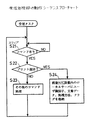
図12と図13とは、画像形成装置の動作を示したものである。各フローチャートはマルチタスクモニタの管理下で並行して動作を行っている。 12 and 13 illustrate the operation of the image forming apparatus. Each flowchart operates in parallel under the control of the multitask monitor.
図12は、画像形成装置の受信処理部のフローチャートである。アイドル状態ではLAN6からのコマンド待ちである(ステップS21)。プリントコマンドを受信すれば(ステップS22)、画像形成装置内のローカルディスクに受信データを格納する(ステップS24)。 FIG. 12 is a flowchart of the reception processing unit of the image forming apparatus. In the idle state, it waits for a command from the LAN 6 (step S21). If the print command is received (step S22), the received data is stored in the local disk in the image forming apparatus (step S24).
以上の動作は図8の構成図において、LAN6からのデータはネットワークインタフェイス部305から入力され、またローカルディスクはファイル部304に相当する。受信処理部としての全体の制御はCPU133が行っている。
In the configuration shown in FIG. 8, the above operation is performed by inputting data from the
図13は、画像形成装置のプリント処理部の動作シーケンスフローチャートである。アイドル状態では画像形成装置内のローカルディスク内にプリントすべきデータがあるか否か常にチェックしている(ステップS31)。プリントすべきデータがあった場合、まず即時プリントのフラグをチェックし(ステップS32)、即時プリント可であれば指定された処理方法でプリントを開始する(ステップS35)。またこの時すでにコピージョブが処理中であれば終了までウエイトする(ステップS34)。 FIG. 13 is an operation sequence flowchart of the print processing unit of the image forming apparatus. In the idle state, it is always checked whether or not there is data to be printed in the local disk in the image forming apparatus (step S31). If there is data to be printed, the immediate printing flag is first checked (step S32). If immediate printing is possible, printing is started by the designated processing method (step S35). If the copy job is already being processed at this time, the process waits until the end (step S34).
即時プリント不可ならば、まずコピージョブが処理中か否かを確認する(ステップS36)。もしコピージョブ処理中で割り込み指示があれば(ステップS37)、割り込みモードに入る(ステップS38)。その後は画像形成装置のカードリーダ616にIDカードが入力されるのを待つ(ステップS39)。入力されればIDカードに記録されているユーザIDと画像形成装置のローカルディスクに格納されている文書ファイルのユーザ識別子が合致するか否かを確認する(ステップS40)。合致しなければ操作パネルに警告を表示する(ステップS41)。
If immediate printing is not possible, it is first checked whether the copy job is being processed (step S36). If there is an interrupt instruction during copy job processing (step S37), the interrupt mode is entered (step S38). After that, it waits for an ID card to be input to the
合致すれば該当する文書ファイルの実体が画像形成装置内にあるか否かチェックし(ステップS42)、なければLAN6を経由してファイルサーバからファイル識別子が示すところの文書ファイルを取り込む(ステップS43)。その後指定された処理方法でプリントを実行する(ステップS44)。プリント終了後は、割り込み中か否かを判断し(ステップS45)、割り込み中であれば中断されたコピージョブを再開する(ステップS46)。 If they match, it is checked whether or not the corresponding document file exists in the image forming apparatus (step S42). If not, the document file indicated by the file identifier is fetched from the file server via the LAN 6 (step S43). . Thereafter, printing is executed by the designated processing method (step S44). After printing, it is determined whether or not an interruption is in progress (step S45). If the interruption is in progress, the interrupted copy job is resumed (step S46).
以上の動作は図8の構成図において、プリント実行、カードリーダ制御および操作パネル制御はコネクタ131を介して行われる。またローカルディスクはファイル部304に相当する。プリント処理部としての全体の制御はCPU133が行っている。
In the configuration diagram of FIG. 8, the above operations are performed through the
(リーダ部1の処理/制御)
さらに、次にリーダ部1の処理/制御について説明する:
図14は、図1、2におけるリーダ部1の構成ブロック図である。CCD108から出力された画像データはA/D・SH部110でアナログ/デジタル変換が行われると共に、シェーディング補正が行われる。A/D・SH部110によって処理された画像データは、画像処理部111を介してプリンタ部2へ転送されると共に、インタフェイス部113を介して画像入出力制御部3のコア部308へ転送される。
(Processing / control of reader unit 1)
Further, processing / control of the
FIG. 14 is a configuration block diagram of the
CPU114は、操作部115で設定された設定内容に応じて、画像処理部111及びインタフェイス部113を制御する。例えば、操作部115でトリミング処理を行って複写を行う複写モードが設定されている場合は、画像処理部111でトリミング処理を行わせてプリンタ部2へ転送させる。
The
また、操作部115でファクシミリ送信モードが設定されている場合は、インタフェイス部113から画像データと設定されたモードに応じた制御コマンドをコア部308へ転送させる。このようなCPU114の制御プログラムは、メモリ116に記憶されており、CPU114は、メモリ116を参照しながら制御を行う。また、メモリ116は、CPU114の作業領域としても使用される。
When the facsimile transmission mode is set on the operation unit 115, the
(コア部308の構成説明)
図15はコア部308の構成ブロック図である。リーダ部1からの画像データは、データ処理部121へ転送されると共に、リーダ部1からの制御コマンドは、CPU133へ転送される。
(Description of the configuration of the core unit 308)
FIG. 15 is a configuration block diagram of the
データ処理部121は、前述した図8の各回路で画像の回転処理や変倍処理などの画像処理を行うものであり、リーダ部1からデータ処理部121へ転送された画像データは、リーダ部1から転送された制御コマンドに応じて、インタフェイス部120を介してファクシミリ部301、ファイル部303、ネットワークインタフェイス部305へ転送される。また、ネットワークインタフェイス部305を介して入力された画像を表すコードデータは、データ処理部121に転送された後フォーマッタ部306へ転送されて画像データに展開され、この画像データはデータ処理部121に転送された後、ファクシミリ部301やプリンタ部2へ転送される。
The
ファクシミリ部301からの画像データは、データ処理部121へ転送された後、プリンタ部2やファイル部303、ネットワークインタフェイス部305へ転送される。また、ファイル部303からの画像データは、データ処理部121へ転送された後、プリンタ部2やファクシミリ部301、ネットワークインタフェイス部305へ転送される。CPU133は、メモリ124に記憶されている制御プログラム、及びリーダ部1から転送された制御コマンドに従ってこのような制御を行う。
Image data from the
また、メモリ124は、CPU133の作業領域としても使われる。このように、コア部308を中心に、原稿画像の読み取り、画像のプリント、画像の送受信、画像の保存、コンピュータからのデータの入出力などの機能を複合させた処理を行うことが可能である。
The
図16は、図7におけるワークステーション7またはパソコン8で作成、編集した文書データをこれらで管理しているハードディスクに格納する場合の処理シーケンスを示すフローチャートである。このフローチャートは、ワークステーション7またはパソコン8に据置されたプログラムコードに基づき行われる処理シーケンスを示す。
FIG. 16 is a flowchart showing a processing sequence when document data created and edited by the workstation 7 or the
電源を投入した直後は、ユーザからのコマンド入力待ち(ステップS51)である。ここで、新規ファイル作成が指定されればファイル名の入力を促す表示を行い、ユーザにファイル名を入力させる(ステップS52)。編集が指定されれば、編集を行うべきファイルのファイル名の入力(選択)を促す表示を行い、ユーザにファイル名を入力(選択)させる(ステップS53)。そして、ファイル名の入力(選択)の後、編集モードに入り、ユーザの指示に従い該ファイルの文書の編集を行う(ステップS54)。 Immediately after the power is turned on, it waits for a command input from the user (step S51). Here, if creation of a new file is designated, a display prompting the user to input a file name is performed, and the user is prompted to input a file name (step S52). If editing is designated, a display prompting the user to input (select) the file name of the file to be edited is displayed, and the user inputs (selects) the file name (step S53). Then, after inputting (selecting) the file name, the editing mode is entered, and the document of the file is edited according to the user's instruction (step S54).
編集が終了すれば、ユーザの指示に従い、文書データをワークステーション7またはパソコン8で管理しているハードディスク等のメモリに格納する(ステップS55)。また、ユーザが文書のプリントアウトを指定した場合、まず、プリントアウトすべき文書ファイルの入力(選択)を促す表示を行い、ユーザにファイル名を入力(選択)させる(ステップS56)。
When the editing is completed, the document data is stored in a memory such as a hard disk managed by the workstation 7 or the
その後、プリントアウトさせるべき画像形成装置の指定、枚数/部数指定、後処理方法指定、文書データの保持形態等の処理方法の入力を促す表示を行い、ユーザにそれぞれ入力させる(ステップS57)。そして、即時プリントを行うか否かの入力を促す表示を行い、ユーザに入力させる(ステップS58)。そして、ステップS56で入力したファイル名の文書ファイル(実体)、ユーザIDを含むプリントコマンド(図9の構成)をステップS57で指定した画像形成装置に対し発行する(ステップS59)。 Thereafter, a display prompting the user to input a processing method such as designation of an image forming apparatus to be printed out, designation of the number of copies / number of copies, designation of post-processing method, document data holding form, etc. is performed, and the user inputs each (step S57). Then, a display prompting the user to input whether or not to perform immediate printing is performed, and the user is allowed to input (step S58). Then, a print command (configuration shown in FIG. 9) including the document file (entity) having the file name input in step S56 and the user ID is issued to the image forming apparatus designated in step S57 (step S59).
そして、この画像形成装置からのレスポンスを待ち(ステップS60)、レスポンスがあれば、そのレスポンスに従ったメッセージを出力し表示する。このメッセージは「(ファイル名)のプリント依頼を受け付けました」、「メモリの空き不足で(ファイル名)のプリント依頼は受け付けられません」、「(ファイル名)のプリント終了しました」等である。このメッセージに対し、更なる入力も可能である。 Then, it waits for a response from the image forming apparatus (step S60). If there is a response, a message according to the response is output and displayed. This message is "Print request for (file name) has been accepted", "Print request for (file name) cannot be accepted due to insufficient memory", "Print of (file name) has been completed", etc. is there. Further input is possible for this message.
図17は、図7におけるワークステーション7またはパソコン8で作成、編集した文書データをLAN6上の外部ファイルサーバ9に格納する場合の処理シーケンスを示すフローチャートである。このフローチャートはワークステーション7またはパソコン8に据置されたプログラムコードに基づき行われる処理の流れを示す。
FIG. 17 is a flowchart showing a processing sequence when document data created and edited by the workstation 7 or the
ステップS62〜S65までは前述図16のステップS51〜S54と同様に行う。そして、ステップS66では、文書ファイルの格納先としてファイルサーバ9を指定して、該文書ファイルをファイル名と共に転送し格納させる。
Steps S62 to S65 are performed in the same manner as steps S51 to S54 in FIG. In step S66, the
そして、ステップS67〜S69では前述図16のステップS56〜S58と同様に行う。そして、ステップS70ではステップS67で入力したファイル名(文書ファイルの実体は含まない)、ユーザIDを含むプリントコマンドをステップS68で指定した画像形成装置に対して発行する。このプリントコマンドの中のファイル名を示す情報には該ファイル名の文書ファイルがファイルサーバ9に格納されていることを示す情報も含まれている。
And in step S67-S69, it carries out similarly to step S56-S58 of the above-mentioned FIG. In step S70, a print command including the file name input in step S67 (not including the document file entity) and the user ID is issued to the image forming apparatus specified in step S68. The information indicating the file name in the print command includes information indicating that the document file having the file name is stored in the
そして、ステップS61,S62では、前述のステップS70,S71と同様に画像形成装置からのレスポンスに応じてメッセージを出力する。このメッセージに対し更なる入力が可能である。 In steps S61 and S62, a message is output in response to a response from the image forming apparatus as in steps S70 and S71 described above. Further input is possible for this message.
次に、画像形成装置側の処理の流れについて説明する。以下に示す処理はメモリ124に格納されたプログラムコードに基づきCPU133により制御されるものである。なお、各フローチャートはマルチタスクモニタの管理下で並行して動作を行っている。
Next, the flow of processing on the image forming apparatus side will be described. The processing shown below is controlled by the
図18は、受信タスクによる処理シーケンスを示すフローチャートである。 FIG. 18 is a flowchart showing a processing sequence by the reception task.
アイドル状態ではLAN6からのコマンド待ちである(ステップS73)。プリントコマンドを受信すれば(ステップS74)、このコマンドに含まれる処理内容の中から文書データの保持形態の指定がコードデータであるか判断する(ステップS76)。ここで、コードデータではなくビットマップに展開された画像データでの保持が指定されていれば、イメージメモリ部307または光磁気ディスクに十分な空きがあるか識別する(ステップS77)。空きがあれば、プリントすべき文書ファイルのコードデータをフォーマッタ部306でビットマップ画像に展開し(ステップS78)、イメージメモリ部307または光磁気ディスクに文書データの他ユーザID、処理方法、即時プリントか否かを示すフラグ状態をそれぞれ対応させて記憶する(ステップS79)。どちらに記憶させるかは予め設定しておくものとする。
In the idle state, it waits for a command from the LAN 6 (step S73). If a print command is received (step S74), it is determined from the processing contents included in this command whether the designation of the document data holding form is code data (step S76). Here, if it is designated to hold the image data expanded in the bitmap instead of the code data, it is identified whether there is sufficient space in the
そして、プリントの受付を正常に行えたことを示す受付応答メッセージをプリントを依頼したLAN6上の端末(ワークステーション7またはパソコン8)に出力する。
Then, an acceptance response message indicating that the acceptance of printing has been normally performed is output to the terminal (workstation 7 or personal computer 8) on the
一方、イメージメモリ部307または光磁気ディスクに十分な空きがなければ、プリントを依頼したLAN6上の端末にメモリの容量不足でプリントを受け付けられないことを示す受付不能メッセージを出力する(ステップS81)。そして、このメッセージに対するLAN6上の端末からのレスポンスを待つ(ステップS82)。
On the other hand, if there is not enough free space in the
レスポンスがない場合もしくはコードデータのままで保持するよう変更するレスポンスがあった場合は、文書ファイルはコードデータのままとし、ユーザID、処理方法、フラグ状態をそれぞれ対応させてイメージメモリ部307または光磁気ディスクに記憶する(ステップS79)。一方、キャンセルするようレスポンスがあればステップS73に戻る。
When there is no response or when there is a response to change to keep the code data as it is, the document file is left as code data, and the user ID, processing method, and flag state are respectively associated with the
図19は、プリントタスクによる処理の流れを示すフローチャートである。 FIG. 19 is a flowchart showing the flow of processing by the print task.
アイドル状態ではイメージメモリ部307または光磁気ディスク内にプリントすべきデータがあるか否か常にチェックしている(ステップS83)。プリントすべきデータがあった場合、まず即時プリントの可、不可を示すフラグの状態をチェックし(ステップS84)、即時プリント可であれば指定された処理方法でプリントを開始する(ステップS87)。ただし、このときすでにコピージョブ実行中(ステップS85)であれば、このコピージョブが終了するまで待つ(ステップS86)。
In the idle state, it is always checked whether there is data to be printed in the
一方、即時プリント不可であれば、まず、コピージョブ実行中か否かを確認する(ステップS88)。ここで、コピージョブ実行中で割り込み指示があれば(ステップS89)、割り込みモードに入る(ステップS80)。即ち、実行中のコピージョブを中断してプリントジョブを開始する。そして、図6に示したカードリーダ617にIDカードが入力されるのを待つ(ステップS81)。
On the other hand, if immediate printing is not possible, it is first checked whether or not a copy job is being executed (step S88). If there is an interrupt instruction during execution of the copy job (step S89), the interrupt mode is entered (step S80). In other words, the current copy job is interrupted and the print job is started. Then, it waits for an ID card to be input to the
IDカードが入力されれば、IDカードに記録されているユーザIDとプリントすべき文書データと対応付けて記憶されているユーザIDとが合致するか否かを確認する(ステップS92)。合致しなければ操作表示パネルに警告を表示する(ステップS93)。 If the ID card is input, it is confirmed whether or not the user ID recorded on the ID card matches the user ID stored in association with the document data to be printed (step S92). If not, a warning is displayed on the operation display panel (step S93).
ユーザIDが合致すれば該当する文書ファイルの実体がイメージメモリ部307または光磁気ディスクに記憶されているか否か判断する(ステップS94)。あればその文書ファイルを選択し、なければLAN6を経由してプリントすべき文書ファイルのファイル名の指定によりこのファイルの実体をイメージメモリ部307または光磁気ディスクに取り込む(ステップS95)。
If the user IDs match, it is determined whether the corresponding document file entity is stored in the
次に、プリントすべき文書データがコードデータの状態でイメージメモリ部307または光磁気ディスクに記憶されているか判断し(ステップS96)、コードデータであれば該文書ファイルをフォーマッタ部306に転送してビットマップ画像に展開する(ステップS97)。
Next, it is determined whether the document data to be printed is stored in the
その後指定された処理方法で文書データのプリントを行い、正常に終了するとプリントを依頼したLAN6上の端末に正常終了レスポンスを返す(ステップS98)。プリント終了後は、割り込み中であったか否かを判断し(ステップS99)、割り込み中であった場合は中断していたコピージョブを再開する(ステップS100)。
Thereafter, the document data is printed by the designated processing method, and when the printing is completed normally, a normal completion response is returned to the terminal on the
上記した説明ではユーザIDの入力はIDカードにより行ったが、これに限ることなく操作部115のテンキーなどからの入力であってもよい。 In the above description, the user ID is input using the ID card. However, the input is not limited to this and may be input from the numeric keypad of the operation unit 115.
以上述べたような実施形態によれば、ユーザが所望するタイミングでのプリント開始を行うことができる。 According to the embodiment described above, printing can be started at a timing desired by the user.
また、予め非圧縮のビットマップ画像に展開しておけば、プリント開始までの待ち時間を少なくすることができる。また、このときメモリの空き容量が少なければコードデータのままで保持するようにしたので、メモリの空き容量不足でプリント受付不能にする事態を解消できる。 In addition, if the image is developed in advance into an uncompressed bitmap image, the waiting time until the start of printing can be reduced. At this time, since the code data is held as it is if the free space of the memory is small, it is possible to solve the situation where the print cannot be accepted due to the insufficient free space of the memory.
また、綴じ処理を行わせる場合も画像形成装置の前にユーザが居るときに実行開始させることが可能となり、誤って他の出力紙と一緒に綴じてしまうことを防止できる。 Also, when the binding process is performed, it is possible to start the execution when the user is in front of the image forming apparatus, and it is possible to prevent the binding with other output paper by mistake.
また、複数分のジョブをスプールさせておき、ユーザIDの入力により一度にまとめてプリントさせることが可能となる。 Further, it is possible to spool a plurality of jobs and print them all at once by inputting a user ID.
なお、以上の説明における画像を表すコードデータとはキャラクタコード、プリンタ言語等のコードデータ以外にもビットマップ画像を圧縮コード等を用いてコード化したコードデータとしてもよい。 The code data representing an image in the above description may be code data obtained by coding a bitmap image using a compression code or the like in addition to code data such as a character code and a printer language.
(他の実施例)
本発明は、複数の機器(例えばホストコンピュータ、インタフェイス機器、リーダ、プリンタ等)から構成されるシステムに適用しても一つの機器(例えば複写機、ファクシミリ装置)からなる装置に適用してもよい。
(Other examples)
The present invention can be applied to a system composed of a plurality of devices (for example, a host computer, an interface device, a reader, a printer, etc.) or to an apparatus composed of a single device (for example, a copying machine, a facsimile machine). Good.
また前述した実施形態の機能を実現すべき各種のデバイスを動作させるように該各種デバイスと接続された装置あるいはシステム内のコンピュータに、前記実施形態機能を実現するためのソフトウエアのプログラムコードを供給し、そのシステムあるいは装置のコンピュータ(CPUあるいはMPU)が格納されたプログラムに従って前記各種デバイスを動作させることによって実施したものも本発明の範疇に含まれる。 Also, a program code of software for realizing the functions of the embodiment is supplied to an apparatus connected to the various devices or a computer in the system so as to operate various devices that should realize the functions of the above-described embodiments. However, the present invention includes those implemented by operating the various devices according to a program stored in a computer (CPU or MPU) of the system or apparatus.
またこの場合、前記ソフトウエアのプログラムコード自体が前述した実施形態の機能を実現することになり、そのプログラムコード自体、及びそのプログラムコードをコンピュータに供給するための手段、例えばかかるプログラムコードを格納した記憶媒体は本発明を構成する。 In this case, the software program code itself realizes the functions of the above-described embodiments, and the program code itself and means for supplying the program code to the computer, for example, the program code are stored. The storage medium constitutes the present invention.
かかるプログラムコードを格納する記憶媒体としては例えばフレキシブルディスク、ハードディスク、光ディスク、光磁気ディスク、CD−ROM、磁気テープ、不揮発性のメモリカード、ROM等を用いることができる。 As a storage medium for storing the program code, for example, a flexible disk, a hard disk, an optical disk, a magneto-optical disk, a CD-ROM, a magnetic tape, a nonvolatile memory card, a ROM, or the like can be used.
この記憶媒体として着脱可能なものを採用することにより、この記憶媒体に記憶させたプログラムコードを解読可能な装置を備えた機器に容易に対応させることが可能である。 By adopting a detachable storage medium, it is possible to easily correspond to a device equipped with a device that can decode the program code stored in the storage medium.
またコンピュータが供給されたプログラムコードを実行することにより、前述の実施形態の機能が実現されるだけではなく、そのプログラムコードがコンピュータにおいて稼働しているOS(オペレーティングシステム)、あるいは他のアプリケーションソフト等と協同して前述の実施形態の機能が実現される場合にもかかるプログラムコードは本発明の実施形態に含まれることは言うまでもない。 Further, by executing the program code supplied by the computer, not only the functions of the above-described embodiments are realized, but also the OS (operating system) in which the program code is running on the computer, or other application software, etc. It goes without saying that the program code is also included in the embodiment of the present invention even when the functions of the above-described embodiment are realized in cooperation with the embodiment.
さらに供給されたプログラムコードが、コンピュータの機能拡張ボードやコンピュータに接続された機能拡張ユニットに備わるメモリに格納された後そのプログラムコードの指示に基づいてその機能拡張ボードや機能格納ユニットに携わるCPU等が実際の処理の一部または全部を行い、その処理によって前述した実施形態の機能が実現される場合も本発明に含まれることは言うまでもない。 Further, after the supplied program code is stored in a memory provided in a function expansion board of a computer or a function expansion unit connected to the computer, a CPU engaged in the function expansion board or function storage unit based on the instruction of the program code However, it is needless to say that the present invention also includes a case where the function of the above-described embodiment is realized by performing part or all of the actual processing.
1 リーダ部
2 プリンタ部
3 画像入出力制御部
4 原稿搬送装置
5 用紙(シート)後処理装置
6 LAN(ネットワーク)
7 ワークステーション
8 パソコン
111 画像処理部
114,133 CPU
115 操作部
116,124 メモリ
121 データ処理部
301 ファクシミリ部
302 ハードディスク
303 外部記憶装置
304 ファイル部
305 ネットワークインタフェイス部
306 フォーマッタ部
307 イメージメモリ部
308 コア部
DESCRIPTION OF
7
115
Claims (12)
前記端末より、少なくともユーザを特定するためのユーザID、及び前記端末において生成された印刷データを特定するための識別子を含む、情報を受信する受信手段と、
前記受信手段が受信した前記ユーザIDと前記識別子とをそれぞれ対応付けて管理する管理手段と、
前記印刷データを取得するために、前記ユーザIDを入力する入力手段と、
前記ネットワーク上の端末に格納されている印刷データの中から、前記入力手段から入力されたユーザIDに対応付けて管理されている識別子に基づいて選択された前記印刷データを、前記ネットワークを介して取得する取得手段と、
前記取得手段が取得した印刷データに基づき出力用紙上に画像を印刷する印刷手段とを有することを特徴とする画像形成装置。 An image forming apparatus connected to a terminal that generates print data via a network,
Receiving means for receiving information including at least a user ID for identifying a user and an identifier for identifying print data generated in the terminal from the terminal;
Managing means for managing the user ID and the identifier received by the receiving means in association with each other;
Input means for inputting the user ID to obtain the print data;
The print data selected based on the identifier managed in association with the user ID input from the input means from the print data stored in the terminal on the network is transmitted via the network. Acquisition means for acquiring
An image forming apparatus comprising: a printing unit that prints an image on output paper based on the print data acquired by the acquisition unit.
前記端末より、少なくともユーザを特定するためのユーザID、及び前記端末において生成された印刷データを特定するための識別子を含む、情報を受信する受信工程と、
前記受信工程で受信した前記ユーザIDと前記識別子とを対応付けて管理する管理工程と、
前記印刷データを取得するために、前記ユーザIDを入力する入力工程と、
前記ネットワーク上の端末に格納されている印刷データの中から、前記入力工程で入力されたユーザIDに対応付けて管理された識別子に基づいて選択された前記印刷データを、前記ネットワークを介して取得する取得工程と、
前記取得工程で取得した印刷データに基づき出力用紙上に画像を印刷する印刷工程と、
を有することを特徴とする画像形成装置の制御方法。 A method for controlling an image forming apparatus connected to a terminal that generates print data via a network,
A receiving step of receiving information from the terminal, including at least a user ID for identifying the user and an identifier for identifying the print data generated in the terminal;
A management step of managing the user ID and the identifier received in the reception step in association with each other;
An input step of inputting the user ID to obtain the print data;
The print data selected based on the identifier managed in association with the user ID input in the input step from the print data stored in the terminal on the network is transmitted via the network. An acquisition process to acquire;
A printing step of printing an image on output paper based on the print data acquired in the acquisition step;
A control method for an image forming apparatus, comprising:
前記画像形成装置において、
前記端末より、少なくともユーザを特定するためのユーザID、及び前記ファイルサーバに保持されている印刷データを特定するための識別子を含むコマンドを受信し、
前記受信したユーザIDと識別子とをそれぞれ対応付けて管理し、
前記印刷データを取得するために前記ユーザIDを入力し、
前記ファイルサーバに保持されている印刷データの中から、前記入力されたユーザIDに対応付けて管理されている識別子に基づいて選択された前記印刷データを、前記ファイルサーバから取り込み、
前記取り込んだ印刷データに基づき出力用紙上に画像を印刷することを特徴とする画像形成方法。 This is an image forming method in an image forming system in which a terminal that generates print data, a file server that holds print data, and an image forming apparatus that prints an image on output paper based on the print data are connected to each other via a network. And
In the image forming apparatus,
A command including at least a user ID for specifying a user and an identifier for specifying print data held in the file server is received from the terminal,
Managing the received user ID and identifier in association with each other;
Enter the user ID to obtain the print data,
The print data selected based on the identifier managed in association with the input user ID from the print data held in the file server is fetched from the file server,
An image forming method, wherein an image is printed on output paper based on the captured print data.
Priority Applications (1)
| Application Number | Priority Date | Filing Date | Title |
|---|---|---|---|
| JP2003408821A JP4110084B2 (en) | 1995-12-20 | 2003-12-08 | Image forming apparatus, control method therefor, and image forming method |
Applications Claiming Priority (2)
| Application Number | Priority Date | Filing Date | Title |
|---|---|---|---|
| JP33206695 | 1995-12-20 | ||
| JP2003408821A JP4110084B2 (en) | 1995-12-20 | 2003-12-08 | Image forming apparatus, control method therefor, and image forming method |
Related Parent Applications (1)
| Application Number | Title | Priority Date | Filing Date |
|---|---|---|---|
| JP8339712A Division JPH09251358A (en) | 1995-12-20 | 1996-12-19 | Image forming system, image processor and image processing method |
Publications (3)
| Publication Number | Publication Date |
|---|---|
| JP2004168065A JP2004168065A (en) | 2004-06-17 |
| JP2004168065A5 JP2004168065A5 (en) | 2006-03-23 |
| JP4110084B2 true JP4110084B2 (en) | 2008-07-02 |
Family
ID=32715368
Family Applications (1)
| Application Number | Title | Priority Date | Filing Date |
|---|---|---|---|
| JP2003408821A Expired - Fee Related JP4110084B2 (en) | 1995-12-20 | 2003-12-08 | Image forming apparatus, control method therefor, and image forming method |
Country Status (1)
| Country | Link |
|---|---|
| JP (1) | JP4110084B2 (en) |
Families Citing this family (1)
| Publication number | Priority date | Publication date | Assignee | Title |
|---|---|---|---|---|
| CN101783848B (en) | 2009-01-20 | 2013-03-27 | 京瓷办公信息系统株式会社 | Image forming system |
-
2003
- 2003-12-08 JP JP2003408821A patent/JP4110084B2/en not_active Expired - Fee Related
Also Published As
| Publication number | Publication date |
|---|---|
| JP2004168065A (en) | 2004-06-17 |
Similar Documents
| Publication | Publication Date | Title |
|---|---|---|
| US7006249B2 (en) | Image forming system | |
| JP3501503B2 (en) | Image forming apparatus and sheet post-processing apparatus | |
| US6512899B2 (en) | Image forming apparatus capable of processing images of plural documents | |
| JP2006248672A (en) | Image forming device | |
| JP4111462B2 (en) | Image forming apparatus | |
| EP1753219B1 (en) | Image processing apparatus, image output method, and computer program product | |
| JP2008283470A (en) | Image processing apparatus, program, and image processing method | |
| US6304681B1 (en) | Image processing apparatus for executing image processing in correspondence with portrait and landscape types | |
| US6178273B1 (en) | Image forming apparatus for storing document image in memory by one document feeding operation and the method thereof | |
| JP3719537B2 (en) | Digital copier | |
| JP3938844B2 (en) | Image forming system | |
| US6185009B1 (en) | Data processing apparatus and method | |
| JPH09251358A (en) | Image forming system, image processor and image processing method | |
| JP4110084B2 (en) | Image forming apparatus, control method therefor, and image forming method | |
| JP2004072762A (en) | Digital copying machine and image scanner | |
| JP2003127508A (en) | Off-line printing method, method for generating output control data, and software | |
| JP3782500B2 (en) | Image forming apparatus, image forming method, and image forming system | |
| JP4110162B2 (en) | Image processing apparatus and control method thereof | |
| JPH11341255A (en) | Image formation device and image formation method for image formation device | |
| JP3896205B2 (en) | Image forming apparatus | |
| JP5217796B2 (en) | Image processing apparatus, program, and image processing method | |
| JP3492352B2 (en) | Offline printing method and printing apparatus | |
| JP2004015818A (en) | Off-line printing method, method for preparing output control data, and printing device | |
| JPH10173856A (en) | Image forming device | |
| JPH09231030A (en) | Image formation device and image formation method |
Legal Events
| Date | Code | Title | Description |
|---|---|---|---|
| A521 | Written amendment |
Free format text: JAPANESE INTERMEDIATE CODE: A523 Effective date: 20060202 |
|
| A977 | Report on retrieval |
Free format text: JAPANESE INTERMEDIATE CODE: A971007 Effective date: 20060216 |
|
| A131 | Notification of reasons for refusal |
Free format text: JAPANESE INTERMEDIATE CODE: A131 Effective date: 20060822 |
|
| A521 | Written amendment |
Free format text: JAPANESE INTERMEDIATE CODE: A523 Effective date: 20061023 |
|
| A131 | Notification of reasons for refusal |
Free format text: JAPANESE INTERMEDIATE CODE: A131 Effective date: 20061212 |
|
| A521 | Written amendment |
Free format text: JAPANESE INTERMEDIATE CODE: A523 Effective date: 20070213 |
|
| A131 | Notification of reasons for refusal |
Free format text: JAPANESE INTERMEDIATE CODE: A131 Effective date: 20070515 |
|
| A521 | Written amendment |
Free format text: JAPANESE INTERMEDIATE CODE: A523 Effective date: 20070717 |
|
| A02 | Decision of refusal |
Free format text: JAPANESE INTERMEDIATE CODE: A02 Effective date: 20071218 |
|
| A521 | Written amendment |
Free format text: JAPANESE INTERMEDIATE CODE: A523 Effective date: 20080212 |
|
| A911 | Transfer of reconsideration by examiner before appeal (zenchi) |
Free format text: JAPANESE INTERMEDIATE CODE: A911 Effective date: 20080221 |
|
| TRDD | Decision of grant or rejection written | ||
| A01 | Written decision to grant a patent or to grant a registration (utility model) |
Free format text: JAPANESE INTERMEDIATE CODE: A01 Effective date: 20080401 |
|
| A61 | First payment of annual fees (during grant procedure) |
Free format text: JAPANESE INTERMEDIATE CODE: A61 Effective date: 20080407 |
|
| FPAY | Renewal fee payment (event date is renewal date of database) |
Free format text: PAYMENT UNTIL: 20110411 Year of fee payment: 3 |
|
| R150 | Certificate of patent or registration of utility model |
Free format text: JAPANESE INTERMEDIATE CODE: R150 |
|
| FPAY | Renewal fee payment (event date is renewal date of database) |
Free format text: PAYMENT UNTIL: 20130411 Year of fee payment: 5 |
|
| FPAY | Renewal fee payment (event date is renewal date of database) |
Free format text: PAYMENT UNTIL: 20130411 Year of fee payment: 5 |
|
| FPAY | Renewal fee payment (event date is renewal date of database) |
Free format text: PAYMENT UNTIL: 20140411 Year of fee payment: 6 |
|
| LAPS | Cancellation because of no payment of annual fees |