JP4107774B2 - Punch press control device and control method thereof - Google Patents
Punch press control device and control method thereof Download PDFInfo
- Publication number
- JP4107774B2 JP4107774B2 JP30456599A JP30456599A JP4107774B2 JP 4107774 B2 JP4107774 B2 JP 4107774B2 JP 30456599 A JP30456599 A JP 30456599A JP 30456599 A JP30456599 A JP 30456599A JP 4107774 B2 JP4107774 B2 JP 4107774B2
- Authority
- JP
- Japan
- Prior art keywords
- die
- punch
- mold
- axis
- machining
- Prior art date
- Legal status (The legal status is an assumption and is not a legal conclusion. Google has not performed a legal analysis and makes no representation as to the accuracy of the status listed.)
- Expired - Lifetime
Links
Images


Description
【0001】
【発明の属する技術分野】
本発明は、パンチプレスの制御装置及びその制御方法に関する。
【0002】
【従来の技術】
パンチプレスは、互いに対向して上下動自在に設けられたパンチ金型(上型)とダイ金型(下型)とにより、両者の間に搬入したワーク(板材)の成形及び打抜き等のパンチ加工を連続的に行うものであり、成形及び打ち抜き等の加工種別や成形条件に対応して複数の金型(パンチ金型31とダイ金型33)を図示しないマガジン内に有している。そして、加工目的や加工形状等に応じて、金型を自動金型交換装置(いわゆるATC装置)により順次交換するようになっている。例えば図9に示すように、パンチプレスのプレス部には、互いに対向して、かつ上下動自在にパンチ金型31とダイ金型33が設けられている。ワークWは水平2軸方向に移動自在なXYテーブル(図示せず)によりパンチ金型31とダイ金型33との間に搬入され、パスラインP上を移動し、位置決めされる。パンチ加工後にワークWをXYテーブルで略水平方向に移動し、加工位置に位置決めして連続的に加工している。パンチ金型31を上下動するパンチ軸とダイ金型33を上下動する下ダイ軸の駆動、及びXYテーブルの水平駆動の制御は、通常、予め設定された加工プログラムに従ってNC制御装置等により行われている。
【0003】
パンチ加工後のワークWがXYテーブルにより移動する際の高さ位置は一般的にパスラインPと呼ばれ、NC制御装置等の加工プログラムの中に予め設定されている。通常、パスラインPに沿ってパンチ加工後のワークWを移動する時には、ワークWの下面に傷が付かないように、ダイ金型33はワークWと接触しない高さ位置まで一定設定量だけ退避するようになっている。
また、図9に示すように例えばワークWを下向き成形した場合に、ワークWを移動する時にダイ金型33がワークWの成形部に干渉しないように、下向きの成形高さh1に基づいてダイ金型33が退避する機能がある。この下ダイ軸の退避機能は、個々の金型(ここではパンチ金型31とダイ金型33のセット)に対して設定する機能ではなく、1つのワークWの全ての金型に対して設定されるようになっており、この退避機能が設定されると、全ての金型によるパンチ加工の後にはパスラインPより所定距離だけ離れた高さ位置に下ダイ軸が退避して、ワークWとの干渉を防止することができる。
【0004】
【発明が解決しようとする課題】
しかしながら、上記の従来の下ダイ軸の退避機能には次のような問題がある。いま、例えば図10に示すような形状のワークWを加工する場合を考える。同図において、ワークWは上向き(上方に凸形状)に成形した成形部15に打抜き加工が行われる。このためのダイ金型33は、図11に示すように、ダイ本体11の上面12に上方に突出した突出部13が形成され、ワークWに要する上方凸部の成形高さh2に合わせて前記突出部13の高さh2が設定されている。
上記ワークWの成形部15に打抜きを行う場合、第1の方法としてダイ本体11の上面12をパスラインPに合わせると、上面12をワークWの下面に合わせ、かつ突出部13の上面を成形部15の下面に当接させて打ち抜きした後に、下ダイ軸の高さ位置をそのままにしてワークWを移動することになるので、ワークWとダイ金型33の突出部13とが干渉するという問題がある。
これを解消するために、第2の方法として、前述の下ダイ軸の退避機能を用い、ダイ金型33をワークWから所定距離だけ下降させて、ダイ金型33の突出部13がワークWと干渉しないようにすることはできる。しかしながら、この従来の退避機能は全ての金型に対して実行されるので、他の金型での加工時には必要以上の退避(下降)動作を行うことになり、各加工位置での加工に要する時間が長くなって生産性が低下するという問題がある。
【0005】
本発明は、上記の問題点に着目してなされたものであり、ワークの成形部位に打ち抜き加工を行う際に、パンチ動作完了後のワーク移動時にダイ金型とワークとの干渉が無く、かつ金型種別に適した待機位置に下ダイ軸を待機させることができるパンチプレスの制御装置及びその制御方法を提供することを目的としている。
【0006】
【課題を解決するための手段、作用及び効果】
上記の目的を達成するために、第1発明は、上下動自在に設けたパンチ金型と、パンチ金型に対向して、かつパンチ金型の移動と同一方向に移動自在に設けたダイ金型と、両金型の間に搬送されるワークWをパスラインに沿って略水平2軸方向に移動し位置決めすると共に、この位置決め完了後にパンチ金型及びダイ金型の上下動を制御し、ワークWをパンチ加工する制御器とを備えたパンチプレスの制御装置において、制御器は、パンチ金型及びダイ金型をセットとしたそれぞれの金型毎に、パンチ金型移動のパンチ軸及びダイ金型移動の下ダイ軸の、加工基準位置に基づいた動作パターンを予め設定する設定手段を有すると共に、前記動作パターンにはパンチ動作完了後の下ダイ軸待機位置を設定可能とし、成形加工した部位にさらに打抜き加工を行う場合、加工プログラムの加工基準位置変更指令により、参照金型として設定された成形加工用金型による成形形状の高さデータに基づいて、打抜き加工用金型の加工基準位置を変更すると共に、前記下ダイ軸待機位置を前記加工基準位置に関係なく維持する構成としている。
【0007】
第1発明によると、パンチ軸及び下ダイ軸の動作パターンの中にパンチ動作完了後に下ダイ軸が下降して下ダイ軸待機位置に待機するパターンを予め設定すると共に、この下ダイ軸待機位置を設定可能とし、成形加工した部位にさらに打抜き加工を行う場合、加工プログラムの加工基準位置変更指令により、参照金型として設定された成形加工用金型による成形形状の高さデータに基づいて、打抜き加工用金型の加工基準位置を変更すると共に、前記下ダイ軸待機位置を前記加工基準位置に関係なく維持するようにしたので、打抜き加工を行う成形部位の成形種別や成形高さ等に適合した下ダイ軸待機位置の設定及び移動を容易に行うことができる。これにより、下ダイ軸の待機動作に無駄な移動が無くなり、パンチ加工作業の能率向上が図れる。また、動作パターン及び下ダイ軸待機位置を任意に設定可能となり、様々な金型形状、成形種別に対応したパンチプレス加工ができる。
【0012】
第2発明は、上下動自在に設けたパンチ金型と、パンチ金型に対向して、かつパンチ金型の移動と同一方向に移動自在に設けたダイ金型との間でのパスラインに沿ってのワークの移動、及びパンチ金型とダイ金型の上下動のパンチ動作を交互に実行し、ワークをパンチ加工するパンチプレスの制御方法において、パンチ金型及びダイ金型をセットとしたそれぞれの金型毎に、パンチ金型移動のパンチ軸及びダイ金型移動の下ダイ軸の、加工基準位置に基づいた動作パターンを予め設定すると共に、前記動作パターンにはパンチ動作完了後の下ダイ軸待機位置を設定可能として、成形加工した部位にさらに打抜き加工を行う場合、加工プログラムの加工基準位置変更指令により、参照金型として設定された成形加工用金型による成形形状の高さデータに基づいて、打抜き加工用金型の加工基準位置を変更すると共に、前記下ダイ軸待機位置を前記加工基準位置に関係なく維持する方法としている。
【0013】
第2発明によると、ワークの成形加工部位に打抜き加工を行った後、前記成形加工部位の成形高さに応じてダイ金型を待機位置まで下降させて待機させるようにしたので、それぞれの使用金型の形状、加工種別及び成形高さ等に適した距離だけダイ金型が下降して待機する。したがって、下ダイ軸の待機動作での無駄な動きが無くなり、待機に要する時間を短縮化できる。また、種々の金型に対応して下ダイ軸を確実に待機位置に待機させることができる。これにより、プレス軸とワークとの干渉がなくなるので、ワーク下面の傷の発生をなくし、また干渉によるワークのばたつきによるワークのミクロジョイントの外れをなくすことができる。これらの結果、パンチ加工の生産性を向上できる。さらに、成形部位への打抜き加工が可能となり、パンチ加工可能領域を拡大できるので、適用範囲が広がって生産性を向上できる。
【0014】
【発明の実施の形態】
以下、図面を参照して、実施形態を詳細に説明する。
図1は、本発明に係わるパンチプレスのプレス部のハード構成図である。パンチ軸シリンダ2にはパンチ軸ピストン1が上下動自在に挿入されており、パンチ軸ピストン1の下部の外周部にはストリッパ軸ピストン11が上下動自在に嵌挿されている。ストリッパ軸ピストン11は、ストリッパ軸シリンダ12に上下動自在に挿入されている。パンチ軸ピストン1の下端部にはパンチ金型31が、またストリッパ軸ピストン11の下端部にはストリッパ32がそれぞれ着脱自在に取付けられており、パンチ金型31の先端部は下降時にストリッパ32の下端に設けた貫通孔34から突出可能となっている。
【0015】
パンチ軸シリンダ2の上室7(加圧側)及び下室8(引上側)にはパンチ軸サーボバルブ4が接続され、またストリッパ軸シリンダ12の上室17及び下室18にはストリッパ軸サーボバルブ14が接続されている。パンチ軸サーボバルブ4及びストリッパ軸サーボバルブ14はそれぞれ図示しない油圧ポンプから吐出された圧油の各シリンダへの流量を制御して移動方向及び速度を制御している。パンチ軸シリンダ2とパンチ軸ピストン1との間にはパンチ軸ピストン1の位置を検出するパンチ軸位置検出器6が取付けられており、またストリッパ軸シリンダ12とストリッパ軸ピストン11との間にはストリッパ軸ピストン11の位置を検出するストリッパ軸位置検出器16が取付けられている。
【0016】
下ダイ軸シリンダ22には下ダイ軸ピストン21が上下動自在に挿入されており、下ダイ軸ピストン21の下端部にはダイ金型33が着脱自在に取付けられている。下ダイ軸シリンダ22の上室27(下降側)及び下室28(上昇側)には下ダイ軸サーボバルブ24が接続されており、下ダイ軸サーボバルブ24は図示しない油圧ポンプから吐出された圧油の下ダイ軸シリンダ22への流量を制御して移動方向及び速度を制御している。また、下ダイ軸シリンダ22と下ダイ軸ピストン21との間には、下ダイ軸ピストン21の位置を検出する下ダイ軸位置検出器26が取付けられている。
【0017】
パンチ金型31及びストリッパ32と、ダイ金型33との間の高さには、ワークWの搬送高さを表すパスラインPが設定されている。パスラインP上には、ワークWを支持し、かつ搬送を容易とするブラシやローラ等の支持部材30が配設されており、ワークWは図示しないXYテーブルによってパスラインPに沿って支持部材30上を移動可能となっている。
【0018】
また、パンチ金型31、ストリッパ32及びダイ金型33を備えたプレス部の近傍には、金型交換装置(以後、ATC装置と呼ぶ)25及び金型マガジン23が配設されている。パンチプレス60は加工種別、加工形状及び加工条件等に応じてパンチ金型31、ストリッパ32及びダイ金型33が1つの金型セットとして交換可能となっており、この金型セットは金型マガジン23内に出し入れ自在に配置されている。金型マガジン23は、詳細は後述する制御器40からの制御指令に基づいて各金型の出し入れを制御している。またATC装置25は、制御器40からの金型交換指令に基づいてプレス部に取付けられている金型と金型マガジン23内にストアされている金型とを交換する。
【0019】
制御器40は、マイクロコンピュータ等のコンピュータ装置や数値演算処理装置等の中央演算処理装置(以下、CPUと言う)を備えている。CPUは各検出器6,16,26からの検出信号をそれぞれの入力I/F回路を経由して入力し、詳細は後述するような所定の演算処理に基づいてパンチ軸61、ストリッパ軸62及び下ダイ軸63の各軸速度指令を求め、求めた速度指令を各軸に対応したサーボアンプ9,19,29に出力I/F回路を経由して出力する。また、金型交換時に、ATC装置25及び金型マガジン23にそれぞれ制御指令を出力し、予め設定された加工シーケンスに従って金型交換を制御する。
【0020】
パンチ軸61、ストリッパ軸62及び下ダイ軸63のそれぞれのサーボアンプ9,19,29は、制御器40からの各軸速度指令を電流指令に変換してパンチ軸サーボバルブ4、ストリッパ軸サーボバルブ14及び下ダイ軸サーボバルブ24のソレノイド操作部に出力する。パンチ軸サーボバルブ4、ストリッパ軸サーボバルブ14及び下ダイ軸サーボバルブ24は、電流指令値の大きさに応じた流量となるようにそれぞれのシリンダへの流量を制御する。
【0021】
図2は制御構成ブロック図を示しており、同図に基づいて各制御機能の構成を説明する。
データ設定手段41はパンチ金型31、ストリッパ32及びダイ金型33の金型のそれぞれに応じた金型管理情報及びプレス動作パターンを設定するものであり、データ入力のためのテンキーやデータ種別指定キー、及び入力されたデータを取り込んで記憶させる書込みキー等を有している。設定中のデータ表示又は設定済みデータの表示等が可能なように、データ表示器(例えば、CRT等のグラフィック表示器やLED等の数値表示器を有している)を備えている。なお、データ設定手段41は、制御器40に外部のライン管理コンピュータ等の上位制御装置からデータ通信により設定データを入力するものであってもよい。
【0022】
金型管理情報記憶部42は、データ設定手段41により設定された金型管理情報を、例えば図3に示すように各金型毎に記憶する。例えば、各金型の金型番号に対応して、加工種別、その加工形状、パンチ金型高さ、ダイ高さ、ストリッパ厚さ、ストリッパ圧力、金型耐圧等の金型データを記憶している。
プレス動作パターン記憶部43は、データ設定手段41により設定されたプレス動作パターンを、例えば図4に示すように各動作パターン毎に記憶する。例えば、各動作パターン番号に対応して、加工種別、各プレス軸の移動速度、待機位置等のデータを記憶している。尚、加工種別に応じて制御に要するデータの種類及び数が変わるので、データの種類とその順番をデータ管理情報として予め記憶してあり、このデータ管理情報に基づいてデータの記憶、読み出しが行われる。このとき、各プレス軸の動作パターンは、例えば打抜きの場合には図5に示すようなモーションを設定しており、各プレス軸の速度及びパンチ動作の各プレス軸シーケンス(つまり時間的な関係)と共に、待機位置データがそれぞれ設定されているものである。
【0023】
加工プログラムMPは各ワーク毎に予め設定された加工プログラムであって、パンチ加工のための各種の制御指令及び制御データが所定の加工プログラム言語で記述されている。この加工プログラム言語は例えばNC指令コード、及びPLC言語等の制御プログラム言語などにより記述されており、本実施形態の以下の説明ではNC指令コードを用いた例を示している。
いま、同加工プログラムが例えば図6に示すようなNC指令コードで記述されていると仮定する。同図において、(T)コードは加工対象ワークWの板厚設定指令を表し、(P)コードは待機位置設定指令を表し、Tコードは使用金型選択指令を表し、G00コードはXYテーブルのXY軸移動完了後のパンチ加工指令を表し、またXコード及びYコードはXYテーブルのX軸及びY軸の移動目標位置への移動指令をそれぞれ表している。さらに、M72コードは、パラメータとして記述された金型番号(同図では、T215)の金型データを参照して、各プレス軸によるワークの加工時の高さ位置を規定する加工基準位置を変更する加工基準位置変更指令を表しており、M73コードはこの加工基準位置を元のパスラインに戻すための加工基準位置変更キャンセル指令を表す。
【0024】
加工指令部44は、加工プログラムMPを読み込んで所定のメモリエリアに記憶し、加工プログラムMPに記載された各指令に基づいて各種テーブル類の作成やシーケンス制御のための前処理を行なう。
使用金型情報設定部45は、加工プログラムMP内の使用金型選択指令に基づいて、プログラム実行順番に金型番号を読み出し、この金型番号に対応する金型管理情報を金型管理情報記憶部42から読み出す。次に、読み出した金型管理情報を、図7に示すように、金型使用順番に金型番号に対応したテーブルデータとして設定し記憶する。
【0025】
加工基準位置データ設定部46は、加工指令部44により前処理された使用金型選択指令の金型番号に対応して、金型管理情報記憶部42に記憶されている金型管理情報に基づいて、パンチ加工時のパスライン以外の加工基準位置のデータを自動的に設定する。この設定された加工基準位置データは、例えば図8に示すように、加工時の加工金型番号毎にテーブルデータとして作成される。図6の加工プログラム例で説明すると、「M72(T215)」指令が検索され、加工金型番号「T100」による打抜加工時の参照金型番号「T215」の成形高さデータに基づいて加工基準位置「5.00」が設定される。
【0026】
また加工板厚情報記憶部47は、加工指令部44に記憶されている加工プログラムMPの板厚設定指令の設定情報を読み込んで板厚データとして記憶する。
待機位置情報記憶部48は、加工指令部に記憶されている加工プログラムMPの待機位置設定指令の設定情報を読み込んで待機位置データとして記憶する。尚、この待機位置は、パンチ加工後にXYテーブルによりワークWが移動する前にパンチ金型31及びストリッパ32が前記加工基準位置から一時的に待機するための高さ位置を表している。
【0027】
加工基準位置変更/キャンセル指令検出部(以後、M72/M73検出部と言う)51は、加工指令部44に記憶されている加工プログラムMPの中から加工基準位置変更指令M72及び加工基準位置変更キャンセル指令M73を検索し、検索位置データを動作パターン設定部49に送信する。
またパンチ指令検出部52は、加工指令部44に記憶されている加工プログラムMPの中からパンチ指令(G00コード)をサーチし、サーチしたパンチ指令に基づいてそれぞれのパンチ加工位置での各プレス軸の移動制御指令値が演算される。
【0028】
動作パターン設定部49は、使用金型情報設定部45に設定され記憶された金型管理情報の使用金型の順番に従って、その使用金型のプレス動作パターン番号を読み出し、読み出したプレス動作パターン番号に対応するプレス動作パターンの各設定データをプレス動作パターン記憶部43から読み出す。そして、読み出したプレス動作パターンの設定データに加工板厚情報記憶部47の板厚情報及び待機位置情報記憶部48の待機位置情報を考慮して、実行時の実加工動作パターンのデータを作成し、ストローク制御部転送データ記憶部49aに記憶する。このとき、実行時の下ダイ軸待機点は、待機位置情報記憶部48に記憶されている待機位置データと、実行するプレス動作パターンにより設定されている待機位置データと、実行している加工プログラムMP中の各実行時点までの使用金型の成形高さの内の最大値に設定された待機位置データとの内、最大値が設定されるようになっている。また、動作パターン設定部49は、加工基準位置変更指令M72及び加工基準位置変更キャンセル指令M73の実行時には、パンチ金型31、ストリッパ32及びダイ金型33の加工基準位置の設定及びそのキャンセルをそれぞれ行ない、ストローク制御部転送データ記憶部49aに記憶した実加工動作パターンの加工基準位置データを変更する。そして実加工時に、実行順序に従ってこの実加工動作パターンの設定データをストローク制御部53に出力する。
【0029】
ストローク制御部53は、ストローク制御部転送データ記憶部49aに記憶されている各指令を実行順序に従って動作パターン設定部49から入力し、プレス部のパンチ軸、ストリッパ軸及び下ダイ軸の各軸制御指令を演算し、各軸のサーボアンプ9、19、29に出力する。
【0030】
XYテーブル移動指令検出部54は、加工指令部44に記憶されているXYテーブル移動指令を検索し、ストローク制御部53による各プレス軸の制御実行と同期して(つまり、各プレス軸の移動完了後にワークを移動するように)XYテーブル移動制御指令を演算し、X軸モータ55及びY軸モータ56に出力する。
【0031】
次に、以上の構成による作動を説明する。
加工開始の前に、使用する全ての金型の管理データが金型管理情報記憶部42に記憶されており、また使用する全ての金型のプレス動作パターンがプレス動作パターン記憶部43に記憶されているものとする。ここでは、打ち抜き金型のプレス動作として、動作パターン番号1には、加工面がフラットなダイ金型を使用するデータが記憶されており、下ダイ軸待機位置データは0.00mmが設定されている(図4参照)。また、動作パターン番号2には、加工面がフラットではなく加工部が上方に突出しているダイ金型31(図11参照)を使用するデータが記憶されており、下ダイ軸待機位置データは−2.00mmが設定されている(図4参照)。
【0032】
まず、加工指令部44にてあるワークの加工プログラムMPを読み込み、使用金型情報設定部45により、加工プログラムMPに記述してあるTコードを検索して、使用される金型の順番にその金型番号に対応した金型情報を金型管理情報記憶部42から読み込んで使用金型データを作成する(図7参照)。
【0033】
次に、加工基準位置データ設定部46により、加工プログラムMPに記述してあるM72コード(加工基準位置変更指令)を検索し、M72コードにパラメータとして記述されている金型番号(図6に示すNCプログラム例では、T215)に対応した金型管理情報の中の「高さ」データを金型管理情報記憶部42から読み込んで、パスライン以外の加工基準位置データとして記憶する。
そして、加工プログラムMPに記述してある板厚設定指令の加工材板厚情報データ(図6では(T1.2)コードの「1.2」)を加工板厚情報記憶部47に記憶する。また、加工プログラムMPに記述してある待機位置設定指令の待機位置情報データ(図6では(P5.0)コードの「5.0」)を待機位置情報記憶部48に記憶する。
【0034】
この後、加工プログラムMPに記述された順に各指令が順次実行され、実加工が行なわれるが、以下にその実行順序に従って説明する。
図6に示す「T150」が加工指令部44より読み込まれると、ATC装置25はプレス部に金型番号T150に対応する打ち抜き角金型を装着する。次に、使用金型情報設定部45の使用順番4の金型データが動作パターン設定部49に転送される。そして、転送された金型データの中の動作パターン番号を参照して、プレス動作パターン記憶部43の動作パターン番号のデータ群を動作パターン設定部49に転送する。(今の場合、動作パターン番号は1である)この後、加工板厚情報記憶部47の板厚データを動作パターン設定部49に、また待機位置情報記憶部48の待機位置データを動作パターン設定部49にそれぞれ転送する。これらの転送されたデータに基づいて、動作パターン設定部49は、次に実行する動作パターン1の各設定データ、即ち各プレス軸の制御指令値を演算してストローク制御部53に転送する。そして、ストローク制御部53は、ATC交換位置にあったパンチ軸及びストリッパ軸を上限位置に、下ダイ軸を下限位置に移動し、位置決めする。
【0035】
次に、「G00X1000.Y200.」指令をXYテーブル移動指令検出部54により検出し、このXYテーブル移動指令に基づいてXYテーブルを移動して位置決めする。そして位置決め完了後、パンチ指令検出部52によりストローク制御部53にパンチ指令が送信され、ストローク制御部53はこの時の動作パターンに基づいてプレスのパンチ軸、ストリッパ軸及び下ダイ軸の各軸制御指令を演算して各プレス軸のサーボアンプ9,19,29に出力する。これにより、ワークWに打ち抜き加工が行われる。このパンチ動作完了後、プレス各軸を待機位置に移動させ、位置決めする。このときの下ダイ軸の待機位置は前述のように「0mm」に設定されているので、下ダイ軸はパスラインから移動しない。なお、本実施形態では動作パターン番号1による下ダイ軸の待機位置はパスライン位置に固定されているが、ワークWと下ダイが接触してワークWの下面に傷が付くのを防止するために、XYテーブルを移動する際に、予め設定した下ダイ逃げ量に従って下ダイ軸を退避させてもよい。
このようにして同様に、順次、XYテーブル移動指令及びパンチ指令を実行して、ワークWの打ち抜き加工を行う。
【0036】
次に、「T215」が加工指令部44より読み込まれると、ATC装置25はプレス部に金型番号T215に対応する上エンボス成形金型を装着する。次に、前記「T150」の場合と同様に、使用金型情報の使用順番5の使用金型情報データの中の動作パターン番号(この場合、動作パターン番号は18である)を参照して、当該動作パターン番号のデータ群を動作パターン設定部49に転送する。この後、「T150」の場合と同様に、前記板厚データ及び前記待機位置データを動作パターン設定部49に転送する。これらの転送されたデータに基づいて動作パターン設定部49は各プレス軸の制御指令値を演算してストローク制御部53に転送し、ストローク制御部53はATC交換位置のパンチ軸及びストリッパ軸を上限位置に、下ダイ軸を下限位置に移動し、位置決めする。
【0037】
そして、「G00X150.Y300.」指令に基づいて、XYテーブルが移動して位置決めされ、位置決め完了後、この時の動作パターンに基づいてプレスのパンチ軸、ストリッパ軸及び下ダイ軸の各軸が制御されてワークWに上エンボス成形加工が行われる。そして、このパンチ動作完了後、各プレス軸は待機位置に移動し、位置決めされる。
次に「G00X550.Y200.」指令に基づいて、上記同様にしてXYテーブルが移動して位置決めされ、位置決め完了後、この時の動作パターンに基づいてパンチ動作によりワークWに上エンボス成形加工が行われ、パンチ動作完了後、各プレス軸は待機位置に移動し、位置決めされる。
【0038】
次に、「T100」(打抜き丸金型選択指令)が加工指令部44より読み込まれると、ATC装置25はプレス部に金型番号T100に対応する打抜き丸金型を装着する。次に、前記同様に、使用金型情報の使用順番6の使用金型情報データの中の動作パターン番号(この場合、動作パターン番号は2である)を参照して、当該動作パターン番号のデータ群を動作パターン設定部49に転送する。さらに、前記と同様に、前記板厚データ及び前記待機位置データを動作パターン設定部49に転送する。これらの転送されたデータに基づいて演算された制御指令に従って、ストローク制御部53により、ATC交換位置のパンチ軸及びストリッパ軸は上限位置に、下ダイ軸は下限位置に移動して位置決めされる。
【0039】
次に、「M72(T215)」が加工指令部44より読み込まれ、M72/M73検出部51から動作パターン設定部49にM72指令信号が送信される。これにより、金型番号T100に対応する打抜き丸金型に直前に交換した際にストローク制御部53に転送したデータを、動作パターン設定部49のストローク制御部転送データ記憶部49aに一時的に記憶する。加工基準位置データ設定部46の現在加工金型番号(ここではT100)と参照金型番号(ここではT215)とに該当する加工基準位置データ(ここでは「5.00mm」)を動作パターン設定部49に読み込んで設定し、各プレス軸の加工位置を上記加工基準位置データ値分上下方向にシフトする演算を行い、ストローク制御部53にこの演算したデータを転送する。
【0040】
「G00X150.Y300.」の指令に基づいて、XYテーブルが移動して位置決めされた後、パンチ指令がパンチ指令検出部52よりストローク制御部53に出力され、各プレス軸が動作パターンに従って動作し、ワークWに打抜き加工が行われる。この場合には、以前に「T215」の金型で「X150.Y300.」の位置に上エンボス成形加工した部位に、パスラインに対して加工基準位置データ設定部46に設定されている加工基準位置(ここでは、5.00mm)に相当する距離分上下方向にシフトした位置で、パンチ加工が行われる。したがって、上エンボス成形された形状が打抜きによって変形することはない。
そして、このパンチ加工が完了すると、各プレス軸は待機位置に移動する。このとき、下ダイ軸は下ダイ待機位置データ(ここでは、動作パターン2の下ダイ待機位置データ「−2.00mm」である)に従って、下ダイ先端位置がパスライン位置よりも2mm下方向に位置決めされる。なお、この場合、下ダイ待機位置データが0mmと設定されていたとしても、パスライン位置まで下ダイ先端が下降して逃げるので、ワークWとの干渉はない。
【0041】
次に、「G00X550.Y200.」の指令に基づいて、上記同様に、以前に「T215」の金型で「X550.Y200.」の位置に上エンボス成形加工した部位に、パスラインに対して前記設定した加工基準位置に相当する距離分上下方向にシフトした位置で、パンチ加工が行われる。このとき、「X550.Y200.」の位置にXYテーブルを移動する際に、下ダイ待機位置を「−2.00mm」に設定しているので、下ダイ先端位置がパスラインよりも下側になり、ワークWに干渉することはない。
そして上記パンチ加工が完了した後、各プレス軸は待機点に移動するが、この際も下ダイ待機位置データを「−2.00mm」に設定しているので、下ダイ先端位置がパスラインよりも2mm下方に位置決めされ、ワークWに干渉することはない。
【0042】
次に、「M73」が読み込まれ、M72/M73検出部51より動作パターン設定部49にM73指令信号が送信されると、先の「M72」指令で動作パターン設定部49のストローク制御部転送データ記憶部49aに一時的に記憶した金型番号T100の金型情報データをストローク制御部53に転送する。この後、「G00X200.Y50.」の指令に基づいてXYテーブルが移動し位置決めされたら、パンチ指令検出部52からストローク制御部53にパンチ指令が送信され、各プレス軸が演算されたこの時の実加工動作パターンに従って動作し、ワークWに丸打抜き加工が行われる。この場合の加工基準位置は、加工基準位置データ設定部46のデータではなく、パスライン位置に設定される。
そして、上記パンチ加工が完了すると、各プレス軸は待機位置に移動し、位置決めされる。このとき、下ダイ待機位置が「−2.00mm」と設定されているので、下ダイ先端位置はパスライン位置よりも2mm下方に位置決めされる。このため、下ダイとワークWとの干渉が防止される。
【0043】
以上説明したように、上記実施形態によると、予め金型毎に加工種別、成形高さ及び加工条件等の金型データと共に各プレス軸の動作パターンを金型管理情報として設定して記憶し、動作パターンに下ダイ軸の待機動作パターンを設定可能とすると共に、金型管理情報の中に下ダイ軸待機位置データを記憶可能となっている。そして実加工時には、パンチ加工後に、各金型に対応して設定した待機動作パターン及び待機位置データに基づいて各プレス軸が制御される。
これにより、使用金型の加工種別や成形高さに適した下ダイ軸の待機動作が行われるので、成形部位に打抜き加工を行う場合でも、成形種別、成形高さ及び成形形状等に適合した下ダイ軸待機動作を行うことができる。したがって、下ダイ軸の待機動作に無駄が無くなるので、各箇所でのパンチ加工に要する時間を短縮化でき、能率的に加工でき、よってパンチ加工の生産性を向上できる。
また、様々な形状の金型に対応して下ダイ軸を含む各プレス軸を確実に待機位置に待機させることができ、これによりプレス軸とワークとの干渉がなくなるので、ワーク下面の傷の発生をなくし、製品の外観品質が良い。また、干渉した場合のワークのばたつきによるワークのミクロジョイントの外れをなくすことができるので、外れた場合の後始末作業が不要となる。この結果、パンチ加工の生産性を向上できる。
さらに、種々の成形部位への打抜き加工が能率的に実施可能となり、パンチ加工可能領域を拡大できるので、適用範囲が広がって生産性を向上できる。
【0044】
また、各ワーク毎に対応して加工プログラムに加工材板厚情報指令を記載して板厚データを設定すると、金型管理情報の中に記憶している、使用金型に対応した金型データ、下ダイ軸待機位置データ及び動作パターンと、前記板厚データとに基づいて、使用金型でのパンチ動作の完了後に下ダイ軸が移動すべき待機位置高さがパスラインからの高さとして自動的に演算される。
したがって、加工プログラムによって、使用金型に適合した下ダイ軸待機位置の設定及び移動が容易に可能となり、パンチ加工作業の能率向上が図れる。また、動作パターン及び下ダイ軸待機位置を任意に設定可能となり、様々な金型形状、成形種別に対応したパンチプレス加工ができる。
【図面の簡単な説明】
【図1】 本発明のパンチングプレスのプレス部のハード構成ブロック図である。
【図2】 本発明のパンチングプレスの制御ブロック図である。
【図3】 本発明に係る金型管理情報記憶部の説明図である。
【図4】 本発明に係るプレス動作パターン記憶部の説明図である。
【図5】 本発明に係るプレス動作パターン例の説明図である。
【図6】 本発明に係る加工プログラムの説明図である。
【図7】 本発明に係る使用金型情報設定部の説明図である。
【図8】 本発明に係る加工基準位置データ設定部の説明図である。
【図9】 従来技術のプレス部及び下ダイ軸退避機能の説明図である。
【図10】 上向き成形部位への打抜き加工例の説明図である。
【図11】 図10の打抜き加工例に用いるダイ金型の斜視図である。
【符号の説明】
1…パンチ軸ピストン、2…パンチ軸シリンダ、4…パンチ軸サーボバルブ、6…パンチ軸位置検出器、9,19,29…サーボアンプ、11…ストリッパ軸ピストン、12…ストリッパ軸シリンダ、14…ストリッパ軸サーボバルブ、16…ストリッパ軸位置検出器、21…下ダイ軸ピストン、22…下ダイ軸シリンダ、24…下ダイ軸サーボバルブ、26…下ダイ軸位置検出器、30…支持部材、31…パンチ金型、32…ストリッパ、33…ダイ金型、40…制御器、41…データ設定手段、42…金型管理情報記憶部、43…プレス動作パターン記憶部、44…加工指令部、45…使用金型情報設定部、46…加工基準位置データ設定部、47…加工板厚情報記憶部、48…待機位置情報記憶部、49…動作パターン設定部、51…加工基準位置変更/キャンセル指令検出部(M72/M73検出部)、52…パンチ指令検出部、53…ストローク制御部、54…XYテーブル移動指令検出部、55…X軸モータ、56…Y軸モータ、61…パンチ軸、62…ストリッパ軸、63…下ダイ軸。P…パスライン、W…ワーク、MP…加工プログラム。[0001]
BACKGROUND OF THE INVENTION
The present invention relates to a punch press control device and a control method thereof.
[0002]
[Prior art]
A punch press is a punch mold (upper mold) and die mold (lower mold) that are provided so as to be movable up and down facing each other. Processing is performed continuously, and a plurality of dies (punch dies 31 and die dies 33) are provided in a magazine (not shown) corresponding to processing types such as molding and punching and molding conditions. The molds are sequentially exchanged by an automatic mold exchanging device (so-called ATC device) according to the machining purpose, machining shape, and the like. For example, as shown in FIG. 9, a
[0003]
The height position when the workpiece W after punching moves by the XY table is generally called a pass line P, and is set in advance in a machining program such as an NC controller. Normally, when the workpiece W after punching is moved along the pass line P, the
Further, as shown in FIG. 9, for example, when the workpiece W is formed downward, the
[0004]
[Problems to be solved by the invention]
However, the conventional lower die axis retracting function has the following problems. Consider a case where a workpiece W having a shape as shown in FIG. In the figure, a workpiece W is punched into a forming
When punching the
In order to solve this problem, as a second method, the lower die shaft retracting function is used, the
[0005]
The present invention has been made paying attention to the above problems, and when performing a punching process on a molding part of the workpiece, there is no interference between the die mold and the workpiece when the workpiece is moved after the punching operation is completed, and It is an object of the present invention to provide a punch press control device and a control method thereof that can cause a lower die axis to stand by at a stand-by position suitable for a mold type.
[0006]
[Means, actions and effects for solving the problems]
In order to achieve the above object, a first invention provides a punch die provided so as to be movable up and down, and a die die provided so as to face the punch die and be movable in the same direction as the movement of the punch die. The workpiece and the workpiece W conveyed between the two dies are moved and positioned in a substantially horizontal biaxial direction along the pass line, and after the positioning is completed, the vertical movement of the punch die and the die die is controlled. In a punch press control device having a controller for punching the workpiece W, the controller is: Pa Setting means for presetting an operation pattern based on the machining reference position of the punch axis of the punch mold movement and the lower die axis of the die mold movement for each mold including the punch mold and the die mold. In the operation pattern, the lower die axis standby position after completion of the punching operation can be set, and when the punching process is further performed on the molded part, It was set as a reference mold by the machining reference position change command of the machining program. Based on molding shape height data by molding die , The processing reference position of the die for punching In addition, the lower die axis standby position is maintained regardless of the machining reference position.
[0007]
According to the first invention, a pattern in which the lower die axis descends after the punching operation is completed and waits at the lower die axis standby position is previously included in the operation patterns of the punch axis and the lower die axis. Setting In addition, the lower die axis standby position can be set, and when performing further punching on the molded part, It was set as a reference mold by the machining reference position change command of the machining program. Based on molding shape height data by molding die , The processing reference position of the die for punching Since the lower die axis standby position is maintained regardless of the machining reference position, the lower die axis standby position suitable for the molding type, molding height, etc. of the molding site to be punched and It can be easily moved. Thereby, there is no useless movement in the standby operation of the lower die axis, and the efficiency of the punching work can be improved. Further, the operation pattern and the lower die axis standby position can be arbitrarily set, and punch press processing corresponding to various mold shapes and molding types can be performed.
[0012]
According to a second aspect of the present invention, there is provided a pass line between a punch die that can be moved up and down and a die die that faces the punch die and is movable in the same direction as the movement of the punch die. In the punch press control method for punching the workpiece, the punch die and the die die are set as a set. For each mold, an operation pattern based on the machining reference position of the punch axis of the punch mold movement and the lower die axis of the die mold movement is set in advance, and the operation pattern includes a lower pattern after the punch operation is completed. When it is possible to set the die axis standby position and perform further punching on the molded part, It was set as a reference mold by the machining reference position change command of the machining program. Based on molding shape height data by molding die , The processing reference position of the die for punching In addition, the lower die axis standby position is maintained regardless of the machining reference position.
[0013]
First 2 According to the invention, after the punching process is performed on the molding process part of the workpiece, the die mold is lowered to the standby position according to the molding height of the molding process part, and the die is used. The die die is lowered by a distance suitable for the shape, processing type, molding height, etc., and waits. Therefore, useless movement in the standby operation of the lower die axis is eliminated, and the time required for standby can be shortened. In addition, the lower die shaft can be reliably kept at the standby position corresponding to various molds. As a result, there is no interference between the press shaft and the workpiece, so that scratches on the lower surface of the workpiece can be eliminated, and the disengagement of the micro joint of the workpiece due to flapping of the workpiece due to interference can be eliminated. As a result, the productivity of punching can be improved. In addition, it is possible to perform punching processing on the molding site and expand the punchable region, so that the application range can be expanded and productivity can be improved.
[0014]
DETAILED DESCRIPTION OF THE INVENTION
Hereinafter, embodiments will be described in detail with reference to the drawings.
FIG. 1 is a hardware configuration diagram of a press section of a punch press according to the present invention. A
[0015]
The punch shaft servo valve 4 is connected to the upper chamber 7 (pressure side) and the lower chamber 8 (pull side) of the
[0016]
A lower
[0017]
At the height between the punch die 31 and the
[0018]
Further, in the vicinity of a press section provided with a
[0019]
The
[0020]
The
[0021]
FIG. 2 shows a block diagram of the control configuration, and the configuration of each control function will be described with reference to FIG.
The data setting means 41 sets die management information and a press operation pattern corresponding to each of the punch die 31,
[0022]
The mold management
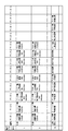
The press operation
[0023]
The machining program MP is a machining program set in advance for each workpiece, and various control commands and control data for punching are described in a predetermined machining program language. The machining program language is described in, for example, an NC command code and a control program language such as a PLC language. In the following description of the present embodiment, an example using the NC command code is shown.
Now, it is assumed that the machining program is described by NC command codes as shown in FIG. 6, for example. In the figure, (T) code represents a plate thickness setting command for the workpiece W to be machined, (P) code represents a standby position setting command, T code represents a used mold selection command, and G00 code represents an XY table. The punching command after completion of the XY axis movement is indicated, and the X code and the Y code indicate movement commands to the X and Y axis movement target positions of the XY table, respectively. Furthermore, the M72 code refers to the die data of the die number (T215 in the figure) described as a parameter, and changes the machining reference position that defines the height position when machining the workpiece with each press axis. The machining reference position change command to be performed is indicated, and the M73 code represents a machining reference position change cancel command for returning the machining reference position to the original pass line.
[0024]
The
The used mold
[0025]
The machining reference position
[0026]
Further, the processing plate thickness
The standby position
[0027]
A machining reference position change / cancel command detection unit (hereinafter referred to as M72 / M73 detection unit) 51 includes a machining reference position change command M72 and a machining reference position change cancel from the machining program MP stored in the
The punch
[0028]
The operation
[0029]
The
[0030]
The XY table movement
[0031]
Next, the operation according to the above configuration will be described.
Before starting the machining, management data for all the molds to be used is stored in the mold management
[0032]
First, the workpiece machining program MP in the
[0033]
Next, the machining reference position
Then, the workpiece thickness information of the workpiece thickness setting command described in the machining program MP (“T1.2” code “1.2” in FIG. 6) is stored in the machining plate thickness
[0034]
Thereafter, each command is sequentially executed in the order described in the machining program MP, and actual machining is performed, which will be described below according to the execution order.
When “T150” shown in FIG. 6 is read from the
[0035]
Next, the “G00X1000.Y200.” Command is detected by the XY table movement
Similarly, the workpiece W is punched by sequentially executing the XY table movement command and the punch command.
[0036]
Next, when “T215” is read from the
[0037]
Based on the “G00X150.Y300.” Command, the XY table is moved and positioned. After the positioning is completed, the press punch axis, stripper axis and lower die axis are controlled based on the operation pattern at this time. Then, the upper embossing process is performed on the workpiece W. Then, after this punching operation is completed, each press shaft moves to the standby position and is positioned.
Next, based on the “G00X550.Y200.” Command, the XY table is moved and positioned in the same manner as described above. After the positioning is completed, the upper embossing process is performed on the workpiece W by the punching operation based on the operation pattern at this time. After completion of the punching operation, each press shaft moves to the standby position and is positioned.
[0038]
Next, when “T100” (punching round die selection command) is read from the
[0039]
Next, “M72 (T215)” is read from the
[0040]
After the XY table is moved and positioned based on the command “G00X150.Y300.”, The punch command is output from the punch
When this punching is completed, each press shaft moves to the standby position. At this time, according to the lower die standby position data (here, the lower die standby position data “−2.00 mm” in the operation pattern 2), the lower die tip position is 2 mm below the pass line position. Positioned. In this case, even if the lower die standby position data is set to 0 mm, there is no interference with the work W because the tip of the lower die moves down to the pass line position and escapes.
[0041]
Next, based on the command of “G00X550.Y200.”, In the same manner as described above, the part that was previously embossed and processed at the position of “X550.Y200.” With the “T215” mold, Punching is performed at a position shifted in the vertical direction by a distance corresponding to the set processing reference position. At this time, when the XY table is moved to the position of “X550.Y200.”, Since the lower die standby position is set to “−2.00 mm”, the lower die tip position is below the pass line. Thus, it does not interfere with the workpiece W.
After the punching is completed, each press shaft moves to the standby point. At this time, the lower die standby position data is set to “−2.00 mm”. Is positioned 2 mm below and does not interfere with the workpiece W.
[0042]
Next, when “M73” is read and an M73 command signal is transmitted from the M72 /
When the punching is completed, each press shaft moves to the standby position and is positioned. At this time, since the lower die standby position is set to “−2.00 mm”, the lower die tip position is positioned 2 mm below the pass line position. For this reason, the interference between the lower die and the workpiece W is prevented.
[0043]
As described above, according to the above embodiment, the operation pattern of each press axis is set and stored as the die management information together with the die data such as the machining type, molding height, and machining conditions for each die in advance. The lower die axis standby operation pattern can be set as the operation pattern, and the lower die axis standby position data can be stored in the mold management information. In actual machining, after punching, each press axis is controlled based on the standby operation pattern and standby position data set for each die.
As a result, the standby operation of the lower die shaft suitable for the processing type and molding height of the mold to be used is performed, so even when punching is performed on the molding site, it is suitable for the molding type, molding height, molding shape, etc. Lower die axis standby operation can be performed. Accordingly, since the standby operation of the lower die axis is not wasted, the time required for punching at each location can be shortened and the machining can be performed efficiently, and thus the productivity of punching can be improved.
In addition, each press shaft including the lower die shaft can be made to stand by at the standby position correspondingly to molds of various shapes, so that there is no interference between the press shaft and the workpiece. Occurrence is eliminated and the appearance quality of the product is good. Moreover, since the disengagement of the micro-joint of the work due to the flapping of the work in the case of interference can be eliminated, the cleanup work after the disengagement becomes unnecessary. As a result, the productivity of punching can be improved.
Furthermore, since it is possible to efficiently perform punching into various molding sites and the punchable region can be expanded, the application range can be expanded and productivity can be improved.
[0044]
In addition, when the workpiece thickness information command is described in the machining program corresponding to each workpiece and the plate thickness data is set, the die data corresponding to the die used is stored in the die management information. Based on the lower die axis standby position data and operation pattern and the plate thickness data, the standby position height at which the lower die axis should move after completion of the punching operation with the mold used is the height from the pass line. Calculated automatically.
Therefore, the machining program can easily set and move the lower die axis standby position suitable for the mold to be used, thereby improving the efficiency of the punching work. Further, the operation pattern and the lower die axis standby position can be arbitrarily set, and punch press processing corresponding to various mold shapes and molding types can be performed.
[Brief description of the drawings]
FIG. 1 is a block diagram of a hardware configuration of a pressing unit of a punching press according to the present invention.
FIG. 2 is a control block diagram of the punching press of the present invention.
FIG. 3 is an explanatory diagram of a mold management information storage unit according to the present invention.
FIG. 4 is an explanatory diagram of a press operation pattern storage unit according to the present invention.
FIG. 5 is an explanatory diagram of an example of a press operation pattern according to the present invention.
FIG. 6 is an explanatory diagram of a machining program according to the present invention.
FIG. 7 is an explanatory diagram of a used mold information setting unit according to the present invention.
FIG. 8 is an explanatory diagram of a processing reference position data setting unit according to the present invention.
FIG. 9 is an explanatory diagram of a conventional press unit and a lower die shaft retracting function.
FIG. 10 is an explanatory diagram of an example of punching into an upward molding site.
11 is a perspective view of a die mold used in the punching example of FIG.
[Explanation of symbols]
DESCRIPTION OF
Claims (2)
制御器(40)は、パンチ金型(31)及びダイ金型(33)をセットとしたそれぞれの金型毎に、パンチ金型(31)移動のパンチ軸及びダイ金型(33)移動の下ダイ軸の、加工基準位置に基づいた動作パターンを予め設定する設定手段を有すると共に、前記動作パターンにはパンチ動作完了後の下ダイ軸待機位置を設定可能とし、
成形加工した部位にさらに打抜き加工を行う場合、加工プログラムの加工基準位置変更指令により、参照金型として設定された成形加工用金型による成形形状の高さデータに基づいて、打抜き加工用金型の加工基準位置を変更すると共に、前記下ダイ軸待機位置を前記加工基準位置に関係なく維持する
ことを特徴とするパンチプレスの制御装置。A punch die (31) provided movably up and down, and a die die (33) provided opposite to the punch die (31) and movable in the same direction as the movement of the punch die (31) The workpiece W conveyed between the two dies (31, 33) is moved and positioned in two substantially horizontal axes along the pass line, and after the positioning is completed, the punch dies (31) and the die dies ( 33) In a punch press control device comprising a controller for controlling the vertical movement of 33) and punching the workpiece (W),
The controller (40) includes a punch axis for moving the punch mold (31) and a die mold (33) movement for each mold including the punch mold (31) and the die mold (33) as a set. The lower die axis has a setting means for presetting an operation pattern based on the machining reference position, and the operation pattern can set a lower die axis standby position after the punch operation is completed,
When further punching is performed on the part that has been molded , the die for punching is based on the height data of the molding shape by the molding die set as the reference die by the machining reference position change command of the machining program A punch press control device characterized in that the lower die axis standby position is maintained regardless of the machining reference position.
パンチ金型(31)及びダイ金型(33)をセットとしたそれぞれの金型毎に、パンチ金型(31)移動のパンチ軸及びダイ金型(33)移動の下ダイ軸の、加工基準位置に基づいた動作パターンを予め設定すると共に、前記動作パターンにはパンチ動作完了後の下ダイ軸待機位置を設定可能として、
成形加工した部位にさらに打抜き加工を行う場合、加工プログラムの加工基準位置変更指令により、参照金型として設定された成形加工用金型による成形形状の高さデータに基づいて、打抜き加工用金型の加工基準位置を変更すると共に、前記下ダイ軸待機位置を前記加工基準位置に関係なく維持する
ことを特徴とするパンチプレスの制御方法。A punch die (31) provided movably up and down, and a die die (33) provided opposite to the punch die (31) and movable in the same direction as the movement of the punch die (31) Of the punch press that punches the workpiece W by alternately executing the movement of the workpiece W along the path line between the two and the punching movement of the punch die (31) and the die die (33) vertically. In the control method,
Machining standards for the punch axis of the punch mold (31) and the lower die axis of the die mold (33) movement for each mold including the punch mold (31) and the die mold (33) as a set In addition to presetting an operation pattern based on the position, it is possible to set a lower die axis standby position after the punch operation is completed in the operation pattern,
When further punching is performed on a part that has been molded , the die for punching is based on the height data of the molding shape by the molding die set as the reference die by the machining reference position change command of the machining program And controlling the lower die axis standby position regardless of the machining reference position.
Priority Applications (1)
| Application Number | Priority Date | Filing Date | Title |
|---|---|---|---|
| JP30456599A JP4107774B2 (en) | 1999-10-26 | 1999-10-26 | Punch press control device and control method thereof |
Applications Claiming Priority (1)
| Application Number | Priority Date | Filing Date | Title |
|---|---|---|---|
| JP30456599A JP4107774B2 (en) | 1999-10-26 | 1999-10-26 | Punch press control device and control method thereof |
Publications (3)
| Publication Number | Publication Date |
|---|---|
| JP2001121219A JP2001121219A (en) | 2001-05-08 |
| JP2001121219A5 JP2001121219A5 (en) | 2005-09-15 |
| JP4107774B2 true JP4107774B2 (en) | 2008-06-25 |
Family
ID=17934532
Family Applications (1)
| Application Number | Title | Priority Date | Filing Date |
|---|---|---|---|
| JP30456599A Expired - Lifetime JP4107774B2 (en) | 1999-10-26 | 1999-10-26 | Punch press control device and control method thereof |
Country Status (1)
| Country | Link |
|---|---|
| JP (1) | JP4107774B2 (en) |
Families Citing this family (1)
| Publication number | Priority date | Publication date | Assignee | Title |
|---|---|---|---|---|
| EP2177291B1 (en) * | 2008-10-20 | 2015-04-15 | TRUMPF Werkzeugmaschinen GmbH + Co. KG | Method for cutting and/or forming of workpieces |
-
1999
- 1999-10-26 JP JP30456599A patent/JP4107774B2/en not_active Expired - Lifetime
Also Published As
| Publication number | Publication date |
|---|---|
| JP2001121219A (en) | 2001-05-08 |
Similar Documents
| Publication | Publication Date | Title |
|---|---|---|
| US5775215A (en) | Machine tool equipped with marking apparatus | |
| JPH11226798A (en) | Vibration-forming method in direct acting press | |
| JP4107774B2 (en) | Punch press control device and control method thereof | |
| WO2001003864A1 (en) | Sheet metal bending system comprising press brake and sheet metal support device, control data creating method therefor, and computer-readable storage medium where the control data is stored | |
| JP3054223B2 (en) | Die management system for punch press | |
| JP3315511B2 (en) | Control method of punch press machine | |
| JP3081659B2 (en) | Punch press machine | |
| JP4301660B2 (en) | Punch press molding method | |
| JPH03216220A (en) | Combined working machine | |
| JP4107770B2 (en) | Punch press work processing method | |
| JP2001047148A (en) | Method for controlling stripper of punch press and controller therefor | |
| JP3405154B2 (en) | Punch press | |
| JP4094191B2 (en) | Punch press control method and control apparatus therefor | |
| JP2001138099A (en) | Punch press control method, and its control device | |
| JP4104255B2 (en) | Punch press stripper | |
| JP5140360B2 (en) | Molding parameter management apparatus and method | |
| JP5281325B2 (en) | Processing machine control device and processing machine control method | |
| CN109457404B (en) | Template sewing machine for down jackets | |
| JPH05131298A (en) | Hydraulic press | |
| JPH05337564A (en) | Method for selecting die in punch press and control device therefor | |
| JPH05131299A (en) | Hydraulic punch press | |
| JP3219785B2 (en) | Punch press control system | |
| JP2503337B2 (en) | Hydraulic press | |
| JP3727445B2 (en) | Mold control device for punch press machine | |
| JPH05131231A (en) | Metal plate working machine |
Legal Events
| Date | Code | Title | Description |
|---|---|---|---|
| A521 | Written amendment |
Free format text: JAPANESE INTERMEDIATE CODE: A523 Effective date: 20050325 |
|
| A621 | Written request for application examination |
Free format text: JAPANESE INTERMEDIATE CODE: A621 Effective date: 20050325 |
|
| A977 | Report on retrieval |
Free format text: JAPANESE INTERMEDIATE CODE: A971007 Effective date: 20070521 |
|
| A131 | Notification of reasons for refusal |
Free format text: JAPANESE INTERMEDIATE CODE: A131 Effective date: 20070529 |
|
| A521 | Written amendment |
Free format text: JAPANESE INTERMEDIATE CODE: A523 Effective date: 20070726 |
|
| A131 | Notification of reasons for refusal |
Free format text: JAPANESE INTERMEDIATE CODE: A131 Effective date: 20071016 |
|
| A521 | Written amendment |
Free format text: JAPANESE INTERMEDIATE CODE: A523 Effective date: 20071213 |
|
| TRDD | Decision of grant or rejection written | ||
| A01 | Written decision to grant a patent or to grant a registration (utility model) |
Free format text: JAPANESE INTERMEDIATE CODE: A01 Effective date: 20080401 |
|
| A61 | First payment of annual fees (during grant procedure) |
Free format text: JAPANESE INTERMEDIATE CODE: A61 Effective date: 20080401 |
|
| FPAY | Renewal fee payment (event date is renewal date of database) |
Free format text: PAYMENT UNTIL: 20110411 Year of fee payment: 3 |
|
| R150 | Certificate of patent or registration of utility model |
Ref document number: 4107774 Country of ref document: JP Free format text: JAPANESE INTERMEDIATE CODE: R150 Free format text: JAPANESE INTERMEDIATE CODE: R150 |
|
| FPAY | Renewal fee payment (event date is renewal date of database) |
Free format text: PAYMENT UNTIL: 20120411 Year of fee payment: 4 |
|
| FPAY | Renewal fee payment (event date is renewal date of database) |
Free format text: PAYMENT UNTIL: 20120411 Year of fee payment: 4 |
|
| FPAY | Renewal fee payment (event date is renewal date of database) |
Free format text: PAYMENT UNTIL: 20130411 Year of fee payment: 5 |
|
| FPAY | Renewal fee payment (event date is renewal date of database) |
Free format text: PAYMENT UNTIL: 20130411 Year of fee payment: 5 |
|
| FPAY | Renewal fee payment (event date is renewal date of database) |
Free format text: PAYMENT UNTIL: 20140411 Year of fee payment: 6 |
|
| EXPY | Cancellation because of completion of term |