JP4107016B2 - Disc brake - Google Patents
Disc brake Download PDFInfo
- Publication number
- JP4107016B2 JP4107016B2 JP2002256192A JP2002256192A JP4107016B2 JP 4107016 B2 JP4107016 B2 JP 4107016B2 JP 2002256192 A JP2002256192 A JP 2002256192A JP 2002256192 A JP2002256192 A JP 2002256192A JP 4107016 B2 JP4107016 B2 JP 4107016B2
- Authority
- JP
- Japan
- Prior art keywords
- pressing force
- brake pad
- force sensor
- brake
- linear motion
- Prior art date
- Legal status (The legal status is an assumption and is not a legal conclusion. Google has not performed a legal analysis and makes no representation as to the accuracy of the status listed.)
- Expired - Fee Related
Links
Images


Landscapes
- Braking Arrangements (AREA)
Abstract
Description
【0001】
【発明の属する技術分野】
本発明は、車両等に搭載されるディスクブレーキに関し、特に、ディスクロータとブレーキパッドとの接触時点を検出し得るディスクブレーキに関する。
【0002】
【従来の技術】
従来、ブレーキペダルの操作を電気的に検出してこれに基づいて電動モータ等のアクチュエータを制御して直動部材を推進する電動ディスクブレーキがある。
【0003】
この電動ディスクブレーキにおいては、ディスクロータとブレーキパッドと接触位置を検出し、この接触位置に基づいてアクチュエータを制御して直動部材を後退させてディスクロータとブレーキパッドとのクリアランス(パッドクリアランス)を管理したり、また、この接触位置を基準として、この基準からのストロークに基づいてブレーキ力を制御したりしている。
【0004】
この電動ディスクブレーキにおける接触位置の検出に関しては、例えば、(1)特開平9−137841号公報に示されるような進退移動部(直動部材)からブレーキパッドに作用する付勢力(押圧力)を検出する推力センサとブレーキパッドの位置を検出する位置センサとを用いてディスクロータとブレーキパッドとの接触位置として設定して、この接触位置に基づいてパッドクリアランスを管理するものがある。
【0005】
また、(2)特開2000−213575公報に示されるように、加圧ロッドと摩擦材接触部材(ともに直動部材)との間に摩擦材接触部材による押圧力を検出する押圧力センサが設けられ、また、摩擦材接触部材(直動部材)の先端部に接点からなる摩擦材接触センサを設け、この摩擦材接触センサにより摩擦材接触部材の摩擦パッド(ブレーキパッド)への接触・非接触に応じてオン−オフ信号を出力することで、摩擦材接触部材と摩擦パッド(ブレーキパッド)との接触を検出し、この接触した位置をストロークの原点として、ストロークに基づいてブレーキ力を制御するものもある。
【0006】
【発明が解決しようとする課題】
しかしながら、上記従来公報(1)の推力センサや従来公報(2)の押圧力センサは、ディスクロータとブレーキパッドとの接触から直動部材の最大推力(約30kN)に至るまでの直動部材とブレーキパッドとの間の押圧力を受けて、その力を検出する必要があるため、計測範囲が広くて耐圧性の高い押圧力センサを用いる必要がある。
【0007】
そして、このような押圧力センサでは、ディスクロータとブレーキパッドとの接触を検出するときのような小さな押圧力に対しては、その計測範囲の広さから出力値の変化は僅かであるため、この僅かな出力値の変化を用いて正確にディスクロータとブレーキパッドとの接触時点を検出することは難しかった。
【0008】
また、従来公報(2)の摩擦材接触センサは、ブレーキパッドと摩擦材接触部材(直動部材)との接触時点を検出するものであるが、通常、ディスクブレーキの非制動時には、引き摺り防止のためにブレーキパッドがディスクロータからパッドスプリング等の力により離されていることから、ブレーキパッドと摩擦材接触部材(直動部材)との接触時点を検出しても、ディスクロータとブレーキパッドとの接触時点を検出することはできなかった。
【0009】
本発明は、上記した技術的背景に鑑みてなされたものであり、その課題とするところは、ディスクロータとブレーキパッドとの接触時点を精度良く検出し得るディスクブレーキを提供することにある。
【0010】
【課題を解決するための手段】
上記課題を解決するため、請求項1の発明は、アクチュエータにより直動部材を推進してブレーキパッドをディスクロータへ押圧して制動力を発生するディスクブレーキにおいて、前記直動部材と前記ブレーキパッドとの間に該直動部材の推進方向に延びて形成される孔と、該孔内に配設され、前記直動部材と前記ブレーキパッドと間の押圧力を受けて該押圧力に対応するアナログ値を出力するとともに前記直動部材または前記ブレーキパッドからの最大入力よりも許容最大入力が小さな押圧力センサと、前記孔内に配設されて前記押圧力センサと前記ブレーキパッドとの間に設けられ、前記直動部材と前記ブレーキパッドとの間の押圧力を前記押圧力センサに伝達すると共に、該押圧力を受けて撓む非金属製で断熱性がある弾性部材と、前記直動部材と前記ブレーキパッドとの間に、前記弾性部材の前記直動部材の推進方向における弾性変形可能な長さよりも短い長さに形成され、前記ブレーキパッドと前記ディスクロータとが接触したのちに無くなる隙間とを有してなることを特徴とする。
【0011】
この請求項1の発明によれば、制動時に直動部材が推進されると、弾性部材は直動部材とブレーキパッドとの間の押圧力を受けて撓みながらこの押圧力を押圧力センサに伝達し、弾性部材が所定量撓むと、直動部材とブレーキパッドとの相対移動を許容していた両者間の隙間が無くなり、それ以降の押圧力は弾性部材を介して押圧力センサに伝達されなくなる。このため、直動部材またはブレーキパッドからの最大入力よりも許容最大入力が小さな押圧力センサはこの間の押圧力に応じたアナログ値を精度良く出力し得るものを使用することができ、ディスクロータとブレーキパッドとの接触時点を精度良く検出することができる。また、弾性部材によって、ブレーキ作動時にブレーキパッドで発生する熱を押圧力センサに直接伝えてしまうことがなくなる。
【0012】
請求項2の発明は、アクチュエータにより直動部材を推進してブレーキパッドをディスクロータへ押圧して制動力を発生するディスクブレーキにおいて、前記直動部材と前記ブレーキパッドとの間に該直動部材の推進方向に延びて形成される孔と、該孔内に配設され、前記直動部材と前記ブレーキパッドと間の押圧力を受けて電気信号を出力するとともに前記直動部材または前記ブレーキパッドからの最大入力よりも許容最大入力が小さな押圧力センサと、前記孔内に配設されて前記押圧力センサと前記ブレーキパッドとの間に設けられ、前記直動部材と前記ブレーキパッドとの間の押圧力を前記押圧力センサに伝達すると共に、該押圧力を受けて撓む非金属製で断熱性がある弾性部材と、前記直動部材と前記ブレーキパッドとの間に、前記弾性部材の前記直動部材の推進方向における弾性変形可能な長さよりも短い長さの隙間が形成されるとともに、前記ブレーキパッドと前記ディスクロータとが接触したのちに前記直動部材と前記ブレーキパッドが当接することを特徴とする。
【0013】
この請求項2の発明によれば、制動時に直動部材が推進されると、弾性部材は直動部材とブレーキパッドとの間の押圧力を受けて撓みながらこの押圧力を押圧力センサに伝達し、弾性部材が所定量撓むと、直動部材とブレーキパッドとが当接するので、それ以降の押圧力が弾性部材を介して押圧力センサに伝達されなくなる。このため、押圧力センサは、制動時の大きな押圧力を受けないので耐久性が向上する。
【0016】
請求項3の発明は、請求項1に記載のディスクブレーキにおいて、前記押圧力センサからの出力を受ける制御装置を有し、該制御装置は前記押圧力センサと前記ブレーキパッドとの間の押圧力に対応するアナログ値が所定値以上のときにブレーキパッドとディスクロータとが接触していると判定し、または、前記押圧力センサと前記ブレーキパッドとの間の押圧力に対応するアナログ値が所定値未満のときにブレーキパッドとディスクロータとが非接触であると判定することを特徴としている。
【0017】
この請求項3の発明によれば、請求項1に記載のディスクブレーキにおいては押圧力センサとして押圧力に応じたアナログ値を精度良く出力し得るものを使用することができるので、この押圧力センサからの出力に基づいて制御装置は、押圧力センサとブレーキパッドとの間の押圧力に対応するアナログ値が所定値以上のときにブレーキパッドとディスクロータとが接触していると判定するか、または、押圧力センサとブレーキパッドとの間の押圧力に対応するアナログ値が所定値未満のときにブレーキパッドとディスクロータとが非接触であると判定することで、ディスクロータとブレーキパッドとの接触時点を精度良く検出することができる。
【0018】
請求項4の発明は、請求項1に記載のディスクブレーキにおいて、前記押圧力センサからの出力を受ける制御装置を有し、該制御装置は、前記押圧力センサと前記ブレーキパッドとの間の押圧力に対応するアナログ値の変化率の差が所定値以上のときにブレーキパッドとディスクロータとの接触時点を判定することを特徴としている。
【0019】
この請求項4の発明によれば、請求項1に記載のディスクブレーキにおいては押圧力センサとして押圧力に応じたアナログ値を精度良く出力し得るものを使用することができるので、この押圧力センサからの出力に基づいて制御装置は、押圧力センサとブレーキパッドとの間の押圧力に対応するアナログ値の変化率の差が所定値以上のときにブレーキパッドとディスクロータとの接触時点を判定することで、ディスクロータとブレーキパッドとの接触時点を精度良く検出することができる。
【0020】
【発明の実施の形態】
以下、本発明の実施の形態を添付図面に基づいて詳細に説明する。
【0021】
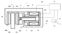
図1は、本発明の第1の実施の形態としての電動ディスクブレーキ装置を模式的に示した断面図であり、図2は第1の実施の形態における本発明の押圧力センサの周辺構造を示す拡大断面図である。
【0022】
本実施の形態におけるディスクブレーキのキャリパ1は、片持ち式の浮動型ディスクブレーキのキャリパとして構成されており、図示しないキャリアを介して車両の非回転部に取り付けられている。
【0023】
キャリパ本体1は、車両の内側に配置されるケース部1Aとケース部1Aからディスクロータ2の外周を跨いで形成された爪部1Bとにより構成されている。
【0024】
ケース部1Aとディスクロータ2との間、また、爪部1Bとディスクロータ2との間には、それぞれブレーキパッド3A,3Bが配置されており、ディスクロータブレーキパッド3A,3Bはディスクロータ2の軸方向に移動可能に前記キャリアに支持されている。
【0025】
ブレーキパッド3A,3Bはディスクロータ2に当接して摩擦力を発生させる摩擦材3Aa,3Baと摩擦材3Aa,3Baに圧着された裏金3Ab,3Bbとから構成されており、このブレーキパッド3A,3Bは非制動時にパッドスプリング4のばね力により、ディスクロータ2からパッドクリアランスsだけ離れるようになっている。
【0026】
キャリパ本体1のケース部1Aには、ブレーキパッド3Aの裏金3Abの背面に当接可能なピストン5(直動部材)と、モータ6と、このモータ6の回転を直線運動に変換して前記ピストン5に伝える回転−直動変換機構7と、ピストン5の位置を検出するためのピストン位置検出部としてモータ6の回転数や回転角度を検出することでピストン5の位置を推定するためのレゾルバ8とを備えている。本実施の形態においては、これらモータ6と回転−直動変換機構7とで直動部材であるピストン5を推進するアクチュエータが構成されている。
【0027】
ここで、回転−直動変換機構7として具体的には、ボールアンドランプ機構、ボールネジ機構、精密ローラネジ機構等が適用される。また、モータ6としては、本実施の形態ではコイル6Aとモータロータ6Bとからなるブラシレスモータを図示しているが、この他に超音波モータ等が適用される。さらに、アクチュエータとしては、上記したモータ6と回転−直動変換機構7との組み合わせによるもののほか、圧電素子等を用いてピストン5を直動させるようにしてもよく、また、油圧アクチュエータを適用することができる。
【0028】
また、上記したレゾルバ8の他にピストン位置検出部としてモータ6の回転量を検出するロータリエンコーダを用いても良いし、ピストン5のストロークを検出するストロークセンサを適用してもよい。
【0029】
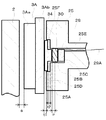
上記ピストン5とブレーキパッド3Aとの間におけるピストン5の当接面5A側には、ピストン5の推進方向に延びて前記当接面5Aに開口し、断面が円形状の孔5Bが穿設されており、この孔5Bには、ピストン5とブレーキパッド3Aとの間の押圧力を受けてその押圧力に対応するアナログ値を出力する押圧力センサ9が底面5Cに設けられている。
【0030】
また、孔5Bの押圧力センサ9よりも開口部5D側には、ピストン5とブレーキパッド3Aとの間の押圧力を押圧力センサ9に伝達するとともに、この押圧力を受けて撓む弾性部材10が配置されている。
【0031】
前記孔5Bの深さは、押圧力センサ9の長さと弾性部材10の長さを合わせた長さよりも短くなっており、このため、前記弾性部材10は、その一部がピストン5の当接面5Aから突出して当接面5Aと裏金3Abとの間に隙間tを形成するようになっている。この隙間tは弾性部材10が撓んだときに弾性変形可能な長さuよりも短く設定されている。
【0032】
前記孔5Bの底面5Cには、前記当接面5Aとは反対側のピストン5の端部まで貫通する貫通孔5Eが開口しており、この貫通孔5Eには押圧力センサ9と後述する制御回路とを接続するリード線9Aが挿通されている。
【0033】
押圧力センサ9は、ブレーキパッド3A,3Bがディスクロータ2に接触するときのピストン5の推進力が5N程度であることから、例えば、最大入力が10N程度のものを使用しており、最大入力が30kNのものに比して小さな押圧力における出力値の変化が大きくとれるものとなっている。そして、この押圧力センサ9として具体的には、圧電素子、磁歪素子、半導体圧力センサ、導電性ゴム、ロードセル、セラミック感圧素子等から適宜選択する。
【0034】
また、弾性部材10は、断面が孔5Bと略同径の円形状をなして形成されており、その硬さはブレーキパッド3A,3Bをディスクロータ2から離す方向に付勢する戻しスプリング4のスプリング力とブレーキパッドを摺動させるときにかかる摺動抵抗力との合力に相当する力以上の力が加わったときに撓み始めるように設定されている。
【0035】
これにより、ブレーキパッド3Aがディスクロータ2に接触するまでは、上記隙間tが保持され、接触した後に、上記隙間tが無くなるようになっている。しかし、この関係が満足されるのであれば、弾性部材10は上記合力よりも小さな力で撓み始めるようにすることもできる。
【0036】
弾性部材10として具体的には、ゴム、エラストマー、樹脂等の非金属製で断熱性があるものから適宜選択する。本実施の形態では、弾性部材10として、上記のような非金属製で断熱性があるものを用いているので、制動時にブレーキパッド3Aで発生する熱が弾性部材10により断熱されて押圧力センサ9に直接伝えられることがない。
【0037】
上述したモータ6、レゾルバ8、押圧力センサ9はそれぞれリード線6C、8A、9Aを介して車両側に設けられた制御装置11に接続されており、この制御装置11によりブレーキペダル12に設けられた操作センサ13の出力に応じたブレーキ制御が行われるほか、押圧力センサ9からの出力に基づいてディスクロータ2とブレーキパッド3A,3Bとの接触位置の判定が行われるようになっている。
【0038】
上記のように構成した電動ディスクブレーキの作用としては、車両の運転者によりブレーキペダル12が踏まれると、上記操作センサ13によりブレーキペダル12が操作されたことを検出し、この検出信号が制御装置11に出力されて制御装置11からモータ6に電圧が印加されモータ6が回転する。
【0039】
このモータ6の回転が回転−直動変換機構7に伝達されてピストン5が推進され、ピストン5によってブレーキパッド3がディスクロータ2に近づいていき、ブレーキパッド3A,3Bがディスクロータ2に当接して制動力が発生するようになる。
【0040】
このようにピストン5が推進されると、弾性部材10はピストン5とブレーキパッド3Aとの間の押圧力を受けて撓みながらこの押圧力を押圧力センサ9に伝達し、弾性部材10が所定量撓むと、ピストン5とブレーキパッド3Aとの相対移動を許容していた両者間の隙間tが無くなり、それ以降の押圧力は弾性部材10を介して押圧力センサ9に伝達されなくなる。押圧力センサ9は、この間の押圧力に応じたアナログ値を精度良く出力するようになっている。
【0041】
運転者が所望の車両制動を完了してブレーキペダル12を戻すと、上記操作センサ13によりブレーキペダル12が操作されたことを検出し、この検出信号が制御装置11に出力されて制御装置11からモータ6に電圧が印加されてモータ6が逆回転する。
【0042】
このモータ6の回転が回転−直動変換機構7に伝達されてピストン5がディスクロータ2から離れる方向に戻され、ブレーキパッド3Aをディスクロータ2から離れて制動力が解除される。
【0043】
このようにピストン5がディスクロータ2から離れる方向に推進されると、ピストン5とブレーキパッド3Aとの相対移動を許容する両者間の隙間tが生じ、弾性部材10は、撓みが解除されつつ、ピストン5とブレーキパッド3Aとの間の押圧力を受けて、この押圧力を押圧力センサ9に伝達する。そして、弾性部材10が自然長まで戻った後、ブレーキパッド3Aはパッドクリアランスsが所定値となるまで戻され、このとき、押圧力センサ9はパッドスプリング4のばね力を受けて微小な値を出力した状態となる。この場合にも押圧力センサ9は、この間の押圧力に応じたアナログ値を精度良く出力するようになっている。
【0044】
つぎに、上述の制御装置11によるディスクロータ2とブレーキパッド3Aとの接触位置(時点)の判定方法について、押圧力センサ9の出力値の変化状態を示す図3の押圧力センサ9の出力線図と、図4のフローチャートとに基づき説明する。
【0045】
なお、図4に示す判定方法は、車両のイグニッションがオンになったときで、オートマチックミッションのPレンジにギヤが設定されている状態やパーキングブレーキがかかっている状態等の停車状態時に行われるものである。また、ディスクロータ2とブレーキパッド3Aとの接触時点を押圧力センサ9の出力値によって正確に検出するには、加速度による慣性力が押圧力センサ9に及ぼす影響を排除する必要がある。そこで、ピストン5を推進する際は一定速度で推進するようにしており、図3に示す押圧力センサ9の出力線図は、時間に対する押圧力センサ9の出力値の変化を線図で表したものとなっている。
【0046】
図3中、P0は、ピストン5がディスクロータ2の方向に推進したときにディスクロータ2とブレーキパッド3Aとの接触時点における押圧力の値を予め実験により求めた値よりも少し大きな値とされた所定値であり、押圧力センサ9の出力値がこの所定値P0以上となったときにはディスクロータ2とブレーキパッド3Aとは必ず接触しているので、この時点を接触時点とみなすことができる。また、Pmaxは、ピストン5がディスクロータ2の方向に推進して、弾性部材10が所定量撓んでブレーキパッド3Aとピストン5との隙間tがなくなったときの押圧力の最大検出値であって、押圧力センサ9の出力値が最大検出値Pmaxとなっている場合には制動力が発生している状態である。
【0047】
まず、図4に示す接触位置の判定が開始される前においては、押圧力センサ9には、パッドクリアランスs(図2参照)を保持するためにパッドスプリング4のバネ力がブレーキパッド3Aおよび弾性部材10を介して伝達されており、押圧力センサ9から微小な値が出力されている(図3のAの状態)。
【0048】
図4のステップ1(図中ステップをSと略しており、以下の説明においてもステップをSと略す)において、ブレーキペダル12が操作されてピストン5がディスクロータ2に向かって推進されていると、接触位置の判定処理が行えないため、ブレーキペダル12が操作されていないか否かを判定し、ブレーキペダル12が操作されていないことを確認した後にS2に移る。
【0049】
S2においてピストン5をディスクロータ2に向かって推進すべくモータ6を一定速度で回転してS3において押圧力センサ9の出力値が所定値P0以上となったか否か、すなわちディスクロータ2とブレーキパッド3Aとが接触したか否かを判定する。
【0050】
このS2における作動においては、まず、ブレーキパッド3Aを静止状態から移動させるためにはパッドスプリング4のばね力に抗すると共に、キャリアに対するブレーキパッド3Aの摺動抵抗にも抗する必要があり、ブレーキパッド3Aを移動させ始めるときの押圧力センサ9の出力値は図3のBの状態からCの状態となるような瞬間的に急な凸形状の変化となる。
【0051】
その後、ブレーキパッド3Aが移動し始めると、ブレーキパッド3Aの移動に伴ってパッドスプリング4が撓められてパッドクリアランスsが小さくなっていくが、このときにはパッドスプリング4を縮める分の力のみでよくなるため、押圧力センサ9の出力値は図3のCの状態からDの状態のような緩やかな変化となる。
【0052】
ブレーキパッド3Aが移動してパッドクリアランスsが0になり、ブレーキパッド3Aの摩擦材3Aaがディスクロータ2に接触すると、ブレーキパッド3Aによりディスクロータ2を押す力が押圧力センサ9に伝達され始めて(Dの状態)から弾性部材10がピストン5とブレーキパッド3Aとの間の押圧力を押圧力センサ9に伝達しつつ撓み始める(Eの状態)まで瞬間的に押圧力センサ9の出力値は上昇し、所定値P0を越えるように変化する。
【0053】
図4のS3において、この所定値P0以上となったこと、すなわち、ディスクロータ2とブレーキパッド3Aとが接触したことを判定すると、S4に移ってこのときのレゾルバ8が検出しているピストン5の位置を接触位置として記憶する。
【0054】
このS4までの処理によって接触位置の判定ができ、この判定した接触位置よってピストン5の位置制御を行うようにしてもよい。しかし、上述のようにピストン5をディスクロータ2に向けて推進させた場合、例えば、ブレーキパッド3Aとキャリアとの摺動面の間に砂利等の異物があった場合には、その異物の抵抗によりブレーキパッド3Aがディスクロータ2に接触する前に押圧力センサ9の出力値が所定値P0以上となってしまう可能性があるため、本実施の形態においては、以下に示すS5以降のような接触位置の判定処理を行う。
【0055】
図4のS4で接触位置の記憶を行った後、S5において再びピストン5をディスクロータ2に向かって推進させて、S6において押圧力センサ9の出力値が最大検出値Pmaxとなったか否か、すなわちピストン5の推進によりブレーキパッド3A,3Bがディスクロータ2を充分押圧している状態にあるかを検出する。
【0056】
このとき、弾性部材10はピストン5とブレーキパッド3Aとの間の押圧力を押圧力センサ9に伝達しつつ撓み始め(Eの状態)、この状態から弾性部材10が所定量撓んでピストン5の当接面5Aとブレーキパッド3Aの裏金3Abとの隙間tが0となり、ピストン5がブレーキパッド3Aに当接する位置に達する(Fの状態)まで、押圧力センサ9は弾性部材を撓めるための押圧力を受けて、その出力値が緩やかに上昇するように変化していく。
【0057】
そして、上述の図3のFの状態となると、弾性部材10は撓まなくなって、弾性部材10により押圧力センサ9へ伝達される押圧力は一定量となり、押圧力センサ9にそれ以上の力が加わらなくなって押圧力センサ9の出力値も一定値の最大検出値Pmaxとなる。
【0058】
図4のS6において、押圧力センサ9の出力値が最大検出値Pmaxとなったことが判定されると、S7に移って今度はモータ6をS2とは逆方向に回転させてピストン5をディスクロータ2から離れる方向へ一定の速度で推進し、S8において押圧力センサ9の出力が所定値P0未満となったか否かを判定し、所定値P0未満となったとき、すなわち、ディスクロータ2とブレーキパッド3Aとが非接触状態となるときにレゾルバ8により検出されるピストン5の位置をS9においてディスクロータ2とブレーキパッド3Aとの接触位置として記憶する。
【0059】
このとき、ピストン5のディスクロータ2から離れる方向への推進によって、ピストン5の当接面5Aとブレーキパッド3Aの裏金3Abとの隙間tが生じ始めると、弾性部材10から押圧力センサ9へ伝達される押圧力が減少し始め(Gの状態)、ピストン5の当接面5Aから突出している弾性部材10の撓みが徐々に解消されて隙間tが増加していくことで、押圧力センサ9の出力値が一定に下降するように変化する。
【0060】
そして、この弾性部材10の撓みが解消された時点(Hの状態)で、ディスクロータ2とブレーキパッド3Aとの接触による押圧力の影響を受けなくなって、瞬間的に押圧力センサ9の出力値の急下降するように変化する。そして、ディスクロータ2とブレーキパッド3Aとが非接触状態となるとパッドスプリング4によってブレーキパッド3Aがディスクロータ2から離れる方向に移動し始める。このとき、押圧力センサ9の出力値は所定値P0を越えて下降しており、ディスクロータ2とブレーキパッド3Aとが非接触状態(Iの状態)となっている。
【0061】
前述したとおり、図4のS9において、押圧力センサ9の出力値が所定値P0未満となったときのピストン5の位置を接触位置として記憶した後に、S10においてディスクロータ2とブレーキパッド3Aとの間が所定のパッドクリアランスsとなるピストン5の位置を算出し、S11で所定のパッドクリアランスsとなるピストン5の位置へピストン5を推進させて接触位置判定処理を終了する。
【0062】
上記S9からS11における、押圧力センサ9の出力値は、上述の図3のIの状態からパッドスプリング4のばね力が押圧力センサ9に伝達されることで緩やかに下降するように変化していき、S11においてレゾルバ8によって所定のパッドクリアランスsとなる位置にピストン5が到達した(Jの状態)ときに、その時点でのパッドスプリング4のばね力を受けてその後は一定値となる。
【0063】
なお、上述した接触位置の判定を、ピストン5がディスクロータ2に向けて推進されたときのS3及びS4における接触位置の判定ではなく、ピストン5をディスクロータ2から離れる方向へ推進させたときのS8及びS9における接触位置の判定とした場合には、上記S3及びS4のステップを省略することができる。
【0064】
上述の図4のフローチャートにおける接触位置(時点)の判定においては、押圧力センサ9の出力値が所定値P0以上か若しくは所定値P0未満かでディスクロータ2とブレーキパッド3Aとの接触若しくは非接触の時点を判定するようにしたが、これに限らず、押圧力センサ9の出力値の変化率を算出し、その変化率の差が所定値以上となったか否かによりディスクロータ2とブレーキパッド3Aとの接触若しくは非接触の時点を判定するようにしてもよい。
【0065】
すなわち、ピストン5がディスクロータ2に向けて推進される場合には、上述したように、押圧力センサ9の出力値が図3におけるDの状態となったときがディスクロータ2とブレーキパッド3Aとの接触時点である。この接触時点を判定するための所定値としては、図3におけるCの状態からDの状態までの押圧力センサ9の出力値の変化率の値ΔKcdと、Dの状態からEの状態までの押圧力センサ9の出力値の変化率の値ΔKdeとの差の値を算出し、誤判定を防止するために、この差の値よりも若干小さい値を所定値K0として設定しておく。
【0066】
そして、接触位置の判定方法としては、上記所定値K0と押圧力センサ9の出力値の微小時間毎の変化率の差の値Δkとを比較して、この値Δkが所定値K0以上となったときにディスクロータ2とブレーキパッド3Aとが非接触の状態から接触に変わることがわかり、これにより接触時点を判定することができるので、この処理を図4のS3の処理と置き換えることで、接触位置の判定が可能となる。
【0067】
ただし、このように接触時点の判定を行った場合には、図3におけるBの状態からCの状態への出力値の変化を接触時点と誤判定してしまう可能性があるため、変化率ΔKが0以上となったとき以降に上述の所定値K0と押圧力センサ9の出力値の微小時間毎の変化率の差の値Δkとの比較を開始すれば、上記の図3におけるBの状態からCの状態への出力値の変化による誤判定を防止することができる。
【0068】
また、ピストン5がディスクロータ2から離れる方向に推進される場合には、上述したように、押圧力センサ9の出力値が図3におけるIの状態となったときがディスクロータ2とブレーキパッド3Aとの非接触時点である。ここで、図3におけるCの状態からDの状態までの押圧力センサ9の出力値の変化率の値ΔKcdとHの状態からIの状態までの押圧力センサ9の出力値の変化率の値ΔKhiの絶対値とは、ほぼ同様の値であり、Dの状態からFの状態までの押圧力センサ9の出力値の変化率の値ΔKdfとIの状態からJの状態までの押圧力センサ9の出力値の変化率の値ΔKijの絶対値とは、ほぼ同様の値であることから、ピストン5がディスクロータ2から離れる方向に推進された場合における接触時点判定のための所定値も上記所定値K0を設定しておく。また、この所定値K0との比較を行うための押圧力センサ9の出力値の微小時間毎の変化率の差の値Δkはマイナスの数値となるので、値Δkの絶対値により所定値K0との比較を行う。
【0069】
そして、接触位置の判定方法としては、上記所定値K0と押圧力センサ9の出力値の微小時間毎の変化率の差の値Δkの絶対値とを比較して、この絶対値が所定値K0以上となったときにディスクロータ2とブレーキパッド3Aとが接触状態から非接触状態となることがわかり、これにより接触時点を判定することができるので、この処理を図4のS8の処理と置き換えることで、非接触位置の判定が可能となる。
【0070】
上記のような接触時点の判定方法によっても、ディスクロータ2とブレーキパッド3Aとの接触時点を精度良く検出することができる。
【0071】
なお、上記接触時点の判定では、所定値K0と押圧力センサ9の出力値の微小時間毎の変化率の差の値Δkとを比較することとしたが、押圧力センサ9の出力値の微小時間毎の変化率の差の値Δkは押圧力センサ9の出力値を二階微分した値と同様であるため、所定値K0と押圧力センサ9の出力値を二階微分した値とを比較することによってもディスクロータ2とブレーキパッド3Aとの接触時点の判定を行うことが可能である。
【0072】
上述したとおり、本第1の実施の形態によれば、制動時にピストン5が推進されると、弾性部材10はピストン5とブレーキパッド3Aとの間の押圧力を受けて撓みながらこの押圧力を押圧力センサ9に伝達し、弾性部材10が所定量撓むと、ピストン5とブレーキパッド3Aとの相対移動を許容していた両者間の隙間tが無くなり、それ以降の押圧力は弾性部材10を介して押圧力センサ9に伝達されなくなる。このため、押圧力センサ9としてはこの間の押圧力に応じたアナログ値を精度良く出力し得るものを使用することができ、ディスクロータ2とブレーキパッド3A,3Bとの接触時点を精度良く検出することができる。また、押圧力センサ9に過大な押圧力が作用することはないので、押圧力センサ9の破損が防止される。
【0073】
また、押圧力センサ9はこの間の押圧力に応じたアナログ値を精度良く出力し得るものを使用することができるため、非制動時におけるディスクロータ2の面振れによってブレーキの引き摺りが発生した場合、この引き摺りによる押圧力センサ9の出力値の変化を検出し、図3のJの状態以降の一定値に対する押圧力センサ9の出力値の変化量によってディスクロータ2の振れ量を算定することが可能となり、算定した振れ量分だけピストン5をディスクロータ2から離す方向にピストン5を制御することでブレーキ引き摺りを防止するといったようなパッドクリアランスの管理を精度よく行うことが可能となる。
【0075】
上記変形例によれば、押圧力検出のための部品が1つですむため、構造が簡易となり、ディスクブレーキの組立が容易になる。
【0076】
つぎに、本発明の第2の実施の形態のディスクブレーキについて図6に基づいて説明する。図6は第2の実施の形態における本発明の押圧力センサの周辺構造を示す断面図である。なお、本第2の実施の形態についての説明においては、上述の第1の実施の形態と同一の部分についてはその説明を省略する。
【0077】
ピストン5とブレーキパッド43Aとの間には、ピストン5の当接面5A側に開口してピストン5の推進方向に延びる孔5Bが穿設されており、この孔5Bには、ピストン5とブレーキパッド43Aとの間の押圧力を受けてその押圧力に対応するアナログ値を出力する押圧力センサ29が底面5Cに設けられている。
【0078】
また、孔5Bの押圧力センサ29よりも開口部5D側には、ピストン5とブレーキパッド43Aとの間の押圧力を押圧力センサ29に伝達するとともにこの押圧力を受けて撓む弾性部材30が配置されている。
【0079】
ピストン5により押圧されるブレーキパッド43Aは、ディスクロータ2に当接する摩擦材43Aaと、この摩擦材43Aaに圧着された裏金43Abとから構成されている。裏金43Aaの前記ピストン5の孔5Bに対向する部分には、孔5Bに入り込んでピストン5とブレーキパッド43Aとの間の押圧力を伝達する突起部43Acが設けられている。
【0080】
前記孔5Bの深さは、押圧力センサ29の長さと弾性部材30の長さと突起部43Acの長さとを合わせた長さよりも短くなっており、当接面5Aと裏金43Abとの間に隙間tを形成するようになっている。この隙間tは弾性部材30が撓んだときに弾性変形可能な長さuよりも短く設定されている。
【0081】
上述したような第2の実施の形態のディスクブレーキによれば、第1の実施の形態におけるディスクブレーキと同様に、制動時にピストン5が推進されると、弾性部材30はピストン5とブレーキパッド43Aとの間の押圧力を突起部43Acより受けて撓みながらこの押圧力を押圧力センサ29に伝達し、弾性部材30が所定量撓むと、ピストン5とブレーキパッド43Aとの相対移動を許容していた両者間の隙間tが無くなり、それ以降の押圧力は弾性部材30を介して押圧力センサ29に伝達されなくなる。このため、押圧力センサ29はこの間の押圧力に応じたアナログ値を精度良く出力し得るものを使用することができ、ディスクロータ2とブレーキパッド43A,43Bとの接触時点を精度良く検出することができる。また、押圧力センサ29に過大な押圧力が作用することはないので、押圧力センサ29の破損が防止される。
【0082】
また、ブレーキ作動時にブレーキパッド43Aで発生する熱は伝達部材34を介して弾性部材30に伝えられるため、押圧力センサ29に直接伝えてしまうことがなく、押圧力センサ29の寿命が延びてディスクブレーキの信頼性が向上する。
【0083】
つぎに、本発明における第3の実施の形態におけるディスクブレーキについて図7に基づいて説明する。図7は第3の実施の形態における本発明の押圧力センサの周辺構造を示す断面図である。なお、本第3の実施の形態についての説明においては、上述した第1の実施の形態、若しくは第2の実施の形態と同一の部分についてはその説明を省略する。
【0084】
ピストン25とブレーキパッド3Aとの間には、ピストン25の当接面25Aに開口してピストン25の推進方向に延びる孔25Bが穿設されており、この孔25Bには、ピストン25のブレーキパッド3Aとの押圧力を受けてその押圧力に対応するアナログ値を出力する押圧力センサ29が底面25Cに設けられている。
【0085】
また、孔25Bの押圧力センサ29よりも開口部25D側には、ピストン5とブレーキパッド3Aとの間の押圧力を押圧力センサ9に伝達するとともにこの押圧力を受けて撓む弾性部材30が配置されている。
【0086】
孔25Bの開口部25D側には段部25Fが形成されており、この段部25Fには、ブレーキパッド3Aからの反力を弾性部材30に伝達する伝達部材34が摺動可能に設けられている。
【0087】
伝達部材34は、セラミックやエンジニアリングプラスティック等の高硬度で断熱性のある材料で形成されており、ピストン25とブレーキパッド3Aとの間の押圧力を弾性部材30を介して押圧力センサ29に伝達するようになっている。
【0088】
上記孔25Bの深さは、押圧力センサ29の長さと弾性部材30の長さと弾性部材34の長さとを合わせた長さよりも短くなっており、また、伝達部材34の一部がピストン25の当接面25Aから突出して当接面25Aと裏金3Abとの間に隙間t1を形成するようになっている。この隙間t1は弾性部材30が撓んだときに弾性変形可能な長さuよりも短く設定されている。
【0089】
また、ピストン25の段部25Fと伝達部材34との対向面間には、隙間t1よりも長い隙間t2が形成されており(t1<t2)、隙間t1がなくなる前にピストン25の段部25Fと伝達部材34との対向面同士が当接しないようになっている。
【0090】
上述したような第3の実施の形態のディスクブレーキによれば、第1の実施の形態におけるディスクブレーキと同様に、制動時にピストン25が推進されると、弾性部材30はピストン25とブレーキパッド3Aとの間の押圧力を伝達部材34より受けて撓みながらこの押圧力を押圧力センサ29に伝達し、弾性部材30が所定量撓むと、ピストン25とブレーキパッド3Aとの相対移動を許容していた両者間の隙間t1が無くなり、それ以降の押圧力は弾性部材30を介して押圧力センサ29に伝達されなくなる。このため、押圧力センサ29はこの間の押圧力に応じたアナログ値を精度良く出力し得るものを使用することができ、ディスクロータ2とブレーキパッド3A,3Bとの接触時点を精度良く検出することができる。また、押圧力センサ29に過大な押圧力が作用することはないので、押圧力センサ29の破損を防止することができる。
【0091】
また、制動時にブレーキパッド3Aで発生する熱は、断熱性を有する伝達部材34及び弾性部材30により断熱されているため、制動時にブレーキパッド3Aで発生する熱を押圧力センサ29に直接伝えてしまうことがなく、押圧力センサ29の寿命が延びてディスクブレーキの信頼性が向上する。
【0092】
なお、上述の第3の実施の形態においては、隙間t1よりも隙間t2を長くして、隙間t1をブレーキパッド3Aとディスクロータ2とが接触した後になくなる隙間としたが、逆に、隙間t2よりも隙間t1を長くして(t1>t2)隙間t2をブレーキパッド3Aとディスクロータ2とが接触した後になくなる隙間としてもよく、この場合に伝達部材34は本発明におけるブレーキパッド3Aの一部として機能することになる。
【0093】
また、上述の第1乃至第3の実施の形態及び変形例においては、押圧力センサ9,19,29及び弾性部材10,30をピストン5の孔5B,25B内に収容するものを例に説明したが、これ限らず、ブレーキパッド3A,43A若しくは伝達部材34に孔を設けて、この孔内に押圧力センサ9,19,29と弾性部材10,30とを収容するようにしてもよい。
【0094】
さらに、上述の第1乃至第3の実施の形態においては、ブレーキパッド3A,43Aと押圧力センサ9,29との間に弾性部材10,30を設ける構成としたがこれに限らず、押圧力センサ9,29とピストン5,25との間に弾性部材10,30を設けてもよい。
【0095】
【発明の効果】
請求項1の発明に係るディスクブレーキにおいては、アクチュエータにより直動部材を推進してブレーキパッドをディスクロータへ押圧して制動力を発生するディスクブレーキにおいて、前記直動部材と前記ブレーキパッドとの間に該直動部材の推進方向に延びて形成される孔と、該孔内に配設され、前記直動部材と前記ブレーキパッドと間の押圧力を受けて該押圧力に対応するアナログ値を出力するとともに前記直動部材または前記ブレーキパッドからの最大入力よりも許容最大入力が小さな押圧力センサと、前記孔内に配設されて前記押圧力センサと前記ブレーキパッドとの間に設けられ、前記直動部材と前記ブレーキパッドとの間の押圧力を前記押圧力センサに伝達すると共に、該押圧力を受けて撓む非金属製で断熱性がある弾性部材と、前記直動部材と前記ブレーキパッドとの間に、前記弾性部材の前記直動部材の推進方向における弾性変形可能な長さよりも短い長さに形成され、前記ブレーキパッドと前記ディスクロータとが接触したのちに無くなる隙間とを有してなることにより、制動時に直動部材が推進されると、弾性部材は直動部材とブレーキパッドとの間の押圧力を受けて撓みながらこの押圧力を押圧力センサに伝達し、弾性部材が所定量撓むと、直動部材とブレーキパッドとの相対移動を許容していた両者間の隙間が無くなり、それ以降の押圧力は弾性部材を介して押圧力センサに伝達されなくなる。このため、押圧力センサはこの間の押圧力に応じたアナログ値を精度良く出力し得るものを使用することができ、ディスクロータとブレーキパッドとの接触時点を精度良く検出することができる。また、弾性部材が前記押圧力センサと前記ブレーキパッドとの間に設けられることにより、押圧力センサの保護が図れるとともに、弾性部材によって、ブレーキ作動時にブレーキパッドで発生する熱を押圧力センサに直接伝えてしまうことがなくなるので、弾性部材の寿命が延びてディスクブレーキの信頼性が向上する。
【0096】
請求項2の発明に係るディスクブレーキにおいては、アクチュエータにより直動部材を推進してブレーキパッドをディスクロータへ押圧して制動力を発生するディスクブレーキにおいて、前記直動部材と前記ブレーキパッドとの間に該直動部材の推進方向に延びて形成される孔と、該孔内に配設され、前記直動部材と前記ブレーキパッドと間の押圧力を受けて電気信号を出力するとともに前記直動部材または前記ブレーキパッドからの最大入力よりも許容最大入力が小さな押圧力センサと、前記孔内に配設されて前記押圧力センサと前記ブレーキパッドとの間に設けられ、前記直動部材と前記ブレーキパッドとの間の押圧力を前記押圧力センサに伝達すると共に、該押圧力を受けて撓む非金属製で断熱性がある弾性部材と、前記直動部材と前記ブレーキパッドとの間に、前記弾性部材の前記直動部材の推進方向における弾性変形可能な長さよりも短い長さの隙間が形成されるとともに、前記ブレーキパッドと前記ディスクロータとが接触したのちに前記直動部材と前記ブレーキパッドが当接してなることにより、制動時に直動部材が推進されると、弾性部材は直動部材とブレーキパッドとの間の押圧力を受けて撓みながらこの押圧力を押圧力センサに伝達し、弾性部材が所定量撓むと、直動部材とブレーキパッドとが当接するので、それ以降の押圧力が弾性部材を介して押圧力センサに伝達されなくなる。このため、押圧力センサは、制動時の大きな押圧力を受けないので、耐久性が向上する。また、弾性部材が前記押圧力センサと前記ブレーキパッドとの間に設けられることにより、押圧力センサの保護が図れるとともに、弾性部材によって、ブレーキ作動時にブレーキパッドで発生する熱を押圧力センサに直接伝えてしまうことがなくなるので、弾性部材の寿命が延びてディスクブレーキの信頼性が向上する。
【0098】
請求項3の発明に係るディスクブレーキにおいては、前記請求項1に記載したディスクブレーキにおいて、押圧力センサからの出力を受ける制御装置を有し、該制御装置は前記押圧力センサと前記ブレーキパッドとの間の押圧力に対応するアナログ値が所定値以上のときにブレーキパッドとディスクロータとが接触していると判定し、または、前記押圧力センサと前記ブレーキパッドとの間の押圧力に対応するアナログ値が所定値未満のときにブレーキパッドとディスクロータとが非接触であると判定することにより、請求項1に記載のディスクブレーキにおいては押圧力センサとして押圧力に応じたアナログ値を精度良く出力し得るものを使用することができるため、この押圧力センサからの出力に基づいて制御装置は、押圧力センサとブレーキパッドとの間の押圧力に対応するアナログ値が所定値以上のときにブレーキパッドとディスクロータとが接触していると判定するか、または、押圧力センサとブレーキパッドとの間の押圧力に対応するアナログ値が所定値未満のときにブレーキパッドとディスクロータとが非接触であると判定することで、ディスクロータとブレーキパッドとの接触時点を精度良く検出することができる。
【0099】
請求項4の発明に係るディスクブレーキにおいては、前記請求項1に記載したディスクブレーキにおいて、前記押圧力センサからの出力を受ける制御装置を有し、該制御装置は、前記押圧力センサと前記ブレーキパッドとの間の押圧力に対応するアナログ値の変化率の差が所定値以上のときにブレーキパッドとディスクロータとの接触時点を判定することにより、請求項1に記載のディスクブレーキにおいては押圧力センサとして押圧力に応じたアナログ値を精度良く出力し得るものを使用することができるため、この押圧力センサからの出力に基づいて制御装置は、押圧力センサとブレーキパッドとの間の押圧力に対応するアナログ値の変化率の差が所定値以上のときにブレーキパッドとディスクロータとの接触時点を判定することができ、ディスクロータとブレーキパッドとの接触時点を精度良く検出することができる。
【図面の簡単な説明】
【図1】本発明における第1の実施の形態としてのディスクブレーキ装置の全体構造を示す断面図である。
【図2】ディスクブレーキを構成する押圧力センサの周辺構造を示す断面図である。
【図3】押圧力センサ9のブレーキ作動時における出力線図である。
【図4】制御装置11が実行するパッド基準位置の判定方法のフローチャートである。
【図5】第1の実施の形態における変形例の押圧力センサの周辺構造を示す断面図である。
【図6】第2の実施の形態における押圧力センサの周辺構造を示す断面図である。
【符号の説明】
1 キャリパ本体
2 ディスクロータ
3A、3B、43A、43B ブレーキパッド
5 ピストン(直動部材)
5A 当接面
5B 孔
6 モータ(アクチュエータ)
7 回転−直動変換機構(アクチュエータ)
8 レゾルバ
9,19,29 押圧力センサ
10,30 弾性部材
11 制御装置
34 伝達部材
43Ac 突起部[0001]
BACKGROUND OF THE INVENTION
The present invention relates to a disc brake mounted on a vehicle or the like, and more particularly to a disc brake that can detect a contact point between a disc rotor and a brake pad.
[0002]
[Prior art]
2. Description of the Related Art Conventionally, there is an electric disk brake that electrically detects an operation of a brake pedal and controls an actuator such as an electric motor based on this to propel a linear motion member.
[0003]
In this electric disc brake, the contact position between the disc rotor and the brake pad is detected, the actuator is controlled based on this contact position, and the linear motion member is moved backward to provide a clearance (pad clearance) between the disc rotor and the brake pad. In addition, the brake force is controlled based on the stroke from the reference with the contact position as a reference.
[0004]
Regarding the detection of the contact position in this electric disk brake, for example, (1) an urging force (pressing force) acting on the brake pad from an advancing / retreating movement part (linear motion member) as disclosed in JP-A-9-137841 There are some which set as a contact position between the disc rotor and the brake pad using a thrust sensor to detect and a position sensor to detect the position of the brake pad, and manage the pad clearance based on the contact position.
[0005]
(2) As shown in Japanese Patent Laid-Open No. 2000-213575, a pressing force sensor for detecting a pressing force by the friction material contact member is provided between the pressure rod and the friction material contact member (both linear motion members). In addition, a friction material contact sensor comprising a contact point is provided at the tip of the friction material contact member (linear motion member), and the friction material contact sensor makes contact or non-contact of the friction material contact member with the friction pad (brake pad). The contact between the friction material contact member and the friction pad (brake pad) is detected by outputting an on-off signal according to the control, and the braking force is controlled based on the stroke with the contact position as the origin of the stroke. There are also things.
[0006]
[Problems to be solved by the invention]
However, the thrust sensor of the above-mentioned conventional publication (1) and the pressing force sensor of the conventional publication (2) are linear motion members from the contact between the disk rotor and the brake pad to the maximum thrust (about 30 kN) of the linear motion member. Since it is necessary to detect the force received from the brake pad, it is necessary to use a pressure sensor having a wide measurement range and high pressure resistance.
[0007]
And in such a pressing force sensor, for a small pressing force such as when detecting the contact between the disc rotor and the brake pad, the change in the output value is slight due to the wide measurement range. It was difficult to accurately detect the contact point between the disc rotor and the brake pad using this slight change in output value.
[0008]
In addition, the friction material contact sensor of the conventional publication (2) detects the contact point between the brake pad and the friction material contact member (linear motion member). Usually, when the disc brake is not braked, it prevents dragging. For this reason, since the brake pad is separated from the disc rotor by the force of a pad spring or the like, even if the contact point between the brake pad and the friction material contact member (linear motion member) is detected, the disc rotor and the brake pad The time of contact could not be detected.
[0009]
The present invention has been made in view of the above-described technical background, and an object of the present invention is to provide a disc brake capable of accurately detecting the contact point between the disc rotor and the brake pad.
[0010]
[Means for Solving the Problems]
In order to solve the above-mentioned problem, the invention according to
[0011]
According to the first aspect of the present invention, when the linear motion member is propelled during braking, the elastic member receives the pressing force between the linear motion member and the brake pad and transmits this pressing force to the pressing force sensor while bending. When the elastic member bends by a predetermined amount, there is no gap between the linear movement member and the brake pad allowing relative movement, and the subsequent pressing force is not transmitted to the pressing force sensor via the elastic member. . For this reason,Allowable maximum input is smaller than the maximum input from linear motion member or brake padA pressing force sensor that can output an analog value corresponding to the pressing force during this period can be used with high accuracy, and the contact point between the disc rotor and the brake pad can be detected with high accuracy.Further, the elastic member prevents the heat generated in the brake pad from being directly transmitted to the pressing force sensor when the brake is operated.
[0012]
According to a second aspect of the present invention, in a disc brake that generates a braking force by pushing a brake pad against a disc rotor by propelling a linear motion member by an actuator, the linear motion member is interposed between the linear motion member and the brake pad. A hole formed extending in the propulsion direction of the motor, and disposed in the hole, receives an pressing force between the linear motion member and the brake pad, and outputs an electric signal.And the allowable maximum input is smaller than the maximum input from the linear motion member or the brake pad.A pressing force sensor and disposed in the hole.Provided between the pressing force sensor and the brake pad.The pressing force between the linear motion member and the brake pad is transmitted to the pressing force sensor, and is deflected by receiving the pressing force.Non-metallic and heat insulatingA gap having a length shorter than a length of the elastic member that is elastically deformable in the propelling direction of the linear motion member is formed between the elastic member and the linear motion member and the brake pad. The linear motion member and the brake pad come into contact with each other after the disc rotor comes into contact with the disc rotor.
[0013]
According to the invention of
[0016]
Claim3The disc brake according to
[0017]
This claim3According to the invention, the disc brake according to
[0018]
Claim4The disc brake according to
[0019]
This claim4According to the invention, the disc brake according to
[0020]
DETAILED DESCRIPTION OF THE INVENTION
Hereinafter, embodiments of the present invention will be described in detail with reference to the accompanying drawings.
[0021]
FIG. 1 is a cross-sectional view schematically showing an electric disc brake device as a first embodiment of the present invention, and FIG. 2 shows a peripheral structure of a pressing force sensor according to the present invention in the first embodiment. It is an expanded sectional view shown.
[0022]
The
[0023]
The caliper
[0024]
[0025]
The
[0026]
The
[0027]
Here, specifically, a ball-and-ramp mechanism, a ball screw mechanism, a precision roller screw mechanism, or the like is applied as the rotation-linear
[0028]
In addition to the
[0029]
On the
[0030]
An elastic member that transmits the pressing force between the
[0031]
The depth of the
[0032]
A through
[0033]
Since the thrust force of the
[0034]
The
[0035]
Thus, the gap t is held until the
[0036]
Specifically, the
[0037]
The motor 6, the
[0038]
As an operation of the electric disc brake configured as described above, when the
[0039]
The rotation of the motor 6 is transmitted to the rotation / linear
[0040]
When the
[0041]
When the driver completes the desired vehicle braking and returns the
[0042]
The rotation of the motor 6 is transmitted to the rotation / linear
[0043]
When the
[0044]
Next, regarding the method for determining the contact position (time point) between the
[0045]
The determination method shown in FIG. 4 is performed when the vehicle ignition is turned on and when the vehicle is stopped such as when the gear is set in the P range of the automatic mission or when the parking brake is applied. It is. Further, in order to accurately detect the contact point between the
[0046]
In FIG. 3, P0 is a value slightly larger than the value obtained by experiments in advance when the value of the pressing force at the time of contact between the
[0047]
First, before the determination of the contact position shown in FIG. 4 is started, the spring force of the
[0048]
In
[0049]
In S2, the motor 6 is rotated at a constant speed to propel the
[0050]
In the operation in S2, first, in order to move the
[0051]
Thereafter, when the
[0052]
When the
[0053]
In S3 of FIG. 4, when it is determined that the predetermined value P0 or more is reached, that is, it is determined that the
[0054]
The contact position can be determined by the processing up to S4, and the position control of the
[0055]
After storing the contact position in S4 of FIG. 4, the
[0056]
At this time, the
[0057]
Then, when the state of F in FIG. 3 described above is reached, the
[0058]
When it is determined in S6 of FIG. 4 that the output value of the
[0059]
At this time, when the clearance t between the
[0060]
Then, at the time when the bending of the
[0061]
As described above, in S9 of FIG. 4, the position of the
[0062]
In S9 to S11, the output value of the
[0063]
Note that the determination of the contact position described above is not the determination of the contact position in S3 and S4 when the
[0064]
In the determination of the contact position (time point) in the flowchart of FIG. 4 described above, the
[0065]
That is, when the
[0066]
As a method for determining the contact position, the predetermined value K0 is compared with the difference value Δk of the change rate of the output value of the
[0067]
However, when the contact point is determined in this way, the change in the output value from the state B to the state C in FIG. 3 may be erroneously determined as the point of contact, so the rate of change ΔK If the comparison between the predetermined value K0 and the difference value Δk of the change rate of the output value of the
[0068]
Further, when the
[0069]
As a method for determining the contact position, the predetermined value K0 is compared with the absolute value of the difference Δk of the rate of change of the output value of the
[0070]
The contact point between the
[0071]
In the determination of the contact point, the predetermined value K0 is compared with the difference value Δk of the change rate of the output value of the
[0072]
As described above, according to the first embodiment, when the
[0073]
Further, since the
[0075]
According to the above modification, only one component for detecting the pressing force is required, so the structure is simplified and the assembly of the disc brake is facilitated.
[0076]
Next, a disc brake according to a second embodiment of the present invention will be described with reference to FIG. FIG. 6 is a sectional view showing the peripheral structure of the pressing force sensor according to the present invention in the second embodiment. In the description of the second embodiment, the description of the same parts as those of the first embodiment is omitted.
[0077]
Between the
[0078]
Further, on the
[0079]
The
[0080]
The depth of the
[0081]
According to the disc brake of the second embodiment as described above, like the disc brake in the first embodiment, when the
[0082]
Further, since heat generated in the
[0083]
Next, a disc brake according to a third embodiment of the present invention will be described with reference to FIG. FIG. 7 is a sectional view showing the peripheral structure of the pressing force sensor of the present invention in the third embodiment. In the description of the third embodiment, the description of the same parts as those in the first embodiment or the second embodiment described above will be omitted.
[0084]
Between the
[0085]
Further, on the
[0086]
A
[0087]
The
[0088]
The depth of the
[0089]
Further, a gap t2 longer than the gap t1 is formed between the facing surfaces of the
[0090]
According to the disc brake of the third embodiment as described above, like the disc brake in the first embodiment, when the
[0091]
Further, since heat generated in the
[0092]
In the third embodiment described above, the gap t2 is made longer than the gap t1, and the gap t1 is a gap that disappears after the
[0093]
Further, in the first to third embodiments and modifications described above, an example is described in which the
[0094]
Furthermore, in the above-described first to third embodiments, the
[0095]
【The invention's effect】
In the disc brake according to the first aspect of the present invention, in the disc brake in which the linear motion member is propelled by the actuator and the brake pad is pressed against the disc rotor to generate a braking force, between the linear motion member and the brake pad. And a hole formed extending in the propulsion direction of the linearly moving member, and an analog value corresponding to the pressing force is received by receiving a pressing force between the linearly moving member and the brake pad. OutputAnd the allowable maximum input is smaller than the maximum input from the linear motion member or the brake pad.A pressing force sensor and disposed in the hole.Provided between the pressing force sensor and the brake pad.The pressing force between the linear motion member and the brake pad is transmitted to the pressing force sensor, and is deflected by receiving the pressing force.Non-metallic and heat insulatingAn elastic member, and between the linear motion member and the brake pad, are formed with a length shorter than an elastically deformable length in the propulsion direction of the linear motion member of the elastic member, and the brake pad and the disc rotor When the linear motion member is propelled at the time of braking, the elastic member receives the pressing force between the linear motion member and the brake pad and is bent while pushing. When the pressure is transmitted to the pressing force sensor and the elastic member bends by a predetermined amount, there is no gap between the linear motion member and the brake pad, and the subsequent pressing force is passed through the elastic member. It is not transmitted to the pressing force sensor. For this reason, as the pressing force sensor, a sensor that can output an analog value corresponding to the pressing force during this period can be used with high accuracy, and the contact point between the disc rotor and the brake pad can be detected with high accuracy.Further, since the elastic member is provided between the pressing force sensor and the brake pad, the pressing force sensor can be protected and heat generated in the brake pad when the brake is operated is directly applied to the pressing force sensor by the elastic member. Since this is not transmitted, the life of the elastic member is extended and the reliability of the disc brake is improved.
[0096]
In the disc brake according to the second aspect of the present invention, in the disc brake in which the linear motion member is pushed by the actuator and the brake pad is pressed against the disc rotor to generate a braking force, between the linear motion member and the brake pad. And a hole formed extending in the propulsion direction of the linear motion member, and disposed in the hole, and outputs an electrical signal upon receiving a pressing force between the linear motion member and the brake pad.And the allowable maximum input is smaller than the maximum input from the linear motion member or the brake pad.A pressing force sensor and disposed in the hole.Provided between the pressing force sensor and the brake pad.The pressing force between the linear motion member and the brake pad is transmitted to the pressing force sensor, and is deflected by receiving the pressing force.Non-metallic and heat insulatingA gap having a length shorter than a length of the elastic member that is elastically deformable in the propelling direction of the linear motion member is formed between the elastic member and the linear motion member and the brake pad. When the linear motion member and the brake pad come into contact with each other after the disk rotor comes into contact with each other, when the linear motion member is propelled during braking, the elastic member moves between the linear motion member and the brake pad. When the elastic member is deflected by a predetermined amount, the linear motion member and the brake pad come into contact with each other when the elastic member bends by a predetermined amount while receiving the pressing force, and the pressing force is transmitted via the elastic member. It is not transmitted to the pressure sensor. For this reason, since the pressing force sensor does not receive a large pressing force during braking, durability is improved.Further, since the elastic member is provided between the pressing force sensor and the brake pad, the pressing force sensor can be protected and heat generated in the brake pad when the brake is operated is directly applied to the pressing force sensor by the elastic member. Since this is not transmitted, the life of the elastic member is extended and the reliability of the disc brake is improved.
[0098]
Claim3In the disc brake according to the invention, the disc brake according to
[0099]
Claim4In the disc brake according to the present invention, the disc brake according to
[Brief description of the drawings]
FIG. 1 is a cross-sectional view showing the overall structure of a disc brake device as a first embodiment of the present invention.
FIG. 2 is a cross-sectional view showing a peripheral structure of a pressing force sensor constituting a disc brake.
FIG. 3 is an output diagram when the
FIG. 4 is a flowchart of a pad reference position determination method executed by the
FIG. 5 is a cross-sectional view showing a peripheral structure of a pressing force sensor according to a modified example of the first embodiment.
FIG. 6 is a cross-sectional view showing a peripheral structure of a pressing force sensor according to a second embodiment.
[Explanation of symbols]
1 Caliper body
2 Disc rotor
3A, 3B, 43A, 43B Brake pad
5 Piston (linear motion member)
5A Contact surface
5B hole
6 Motor (actuator)
7 Rotation-linear motion conversion mechanism (actuator)
8 Resolver
9, 19, 29 Pressing force sensor
10,30 Elastic member
11 Control device
34 Transmission member
43Ac Protrusion
Claims (4)
前記直動部材と前記ブレーキパッドとの間に該直動部材の推進方向に延びて形成される孔と、
該孔内に配設され、前記直動部材と前記ブレーキパッドと間の押圧力を受けて該押圧力に対応するアナログ値を出力するとともに前記直動部材または前記ブレーキパッドからの最大入力よりも許容最大入力が小さな押圧力センサと、
前記孔内に配設されて前記押圧力センサと前記ブレーキパッドとの間に設けられ、前記直動部材と前記ブレーキパッドとの間の押圧力を前記押圧力センサに伝達すると共に、該押圧力を受けて撓む非金属製で断熱性がある弾性部材と、
前記直動部材と前記ブレーキパッドとの間に、前記弾性部材の前記直動部材の推進方向における弾性変形可能な長さよりも短い長さに形成され、前記ブレーキパッドと前記ディスクロータとが接触したのちに無くなる隙間とを有してなることを特徴とするディスクブレーキ。In a disc brake that generates a braking force by pushing a brake pad against a disc rotor by propelling a linear member by an actuator,
A hole formed extending between the linear motion member and the brake pad in the propulsion direction of the linear motion member;
More than the maximum input from the linear motion member or the brake pad, and an analog value corresponding to the pressure force is output by receiving a pressure force between the linear motion member and the brake pad. A pressure sensor with a small allowable maximum input ,
The pressing force sensor is disposed in the hole and provided between the pressing force sensor and the brake pad, and transmits the pressing force between the linear motion member and the brake pad to the pressing force sensor. A non-metallic elastic member that bends in response to heat ,
Between the linear motion member and the brake pad, the elastic member is formed to have a length shorter than an elastically deformable length in the propulsion direction of the linear motion member, and the brake pad and the disc rotor are in contact with each other. A disc brake characterized by having a gap that disappears later.
前記直動部材と前記ブレーキパッドとの間に該直動部材の推進方向に延びて形成される孔と、
該孔内に配設され、前記直動部材と前記ブレーキパッドと間の押圧力を受けて電気信号を出力するとともに前記直動部材または前記ブレーキパッドからの最大入力よりも許容最大入力が小さな押圧力センサと、
前記孔内に配設されて前記押圧力センサと前記ブレーキパッドとの間に設けられ、前記直動部材と前記ブレーキパッドとの間の押圧力を前記押圧力センサに伝達すると共に、該押圧力を受けて撓む非金属製で断熱性がある弾性部材と、
前記直動部材と前記ブレーキパッドとの間に、前記弾性部材の前記直動部材の推進方向における弾性変形可能な長さよりも短い長さの隙間が形成されるとともに、前記ブレーキパッドと前記ディスクロータとが接触したのちに前記直動部材と前記ブレーキパッドが当接することを特徴とするディスクブレーキ。In a disc brake that generates a braking force by pushing a brake pad against a disc rotor by propelling a linear member by an actuator,
A hole formed extending between the linear motion member and the brake pad in the propulsion direction of the linear motion member;
An electric signal is output in response to the pressing force between the linear motion member and the brake pad, and the allowable maximum input is smaller than the maximum input from the linear motion member or the brake pad. A pressure sensor;
The pressing force sensor is disposed in the hole and provided between the pressing force sensor and the brake pad, and transmits the pressing force between the linear motion member and the brake pad to the pressing force sensor. A non-metallic elastic member that bends in response to heat ,
Between the linear motion member and the brake pad, a gap having a length shorter than the elastic member in the propulsion direction of the linear motion member in the propulsion direction is formed, and the brake pad and the disc rotor are formed. The disc brake is characterized in that the linear motion member and the brake pad come into contact after contact with each other.
Priority Applications (1)
| Application Number | Priority Date | Filing Date | Title |
|---|---|---|---|
| JP2002256192A JP4107016B2 (en) | 2002-08-30 | 2002-08-30 | Disc brake |
Applications Claiming Priority (1)
| Application Number | Priority Date | Filing Date | Title |
|---|---|---|---|
| JP2002256192A JP4107016B2 (en) | 2002-08-30 | 2002-08-30 | Disc brake |
Publications (3)
| Publication Number | Publication Date |
|---|---|
| JP2004092812A JP2004092812A (en) | 2004-03-25 |
| JP2004092812A5 JP2004092812A5 (en) | 2005-10-13 |
| JP4107016B2 true JP4107016B2 (en) | 2008-06-25 |
Family
ID=32061484
Family Applications (1)
| Application Number | Title | Priority Date | Filing Date |
|---|---|---|---|
| JP2002256192A Expired - Fee Related JP4107016B2 (en) | 2002-08-30 | 2002-08-30 | Disc brake |
Country Status (1)
| Country | Link |
|---|---|
| JP (1) | JP4107016B2 (en) |
Cited By (1)
| Publication number | Priority date | Publication date | Assignee | Title |
|---|---|---|---|---|
| KR20160122157A (en) * | 2014-02-17 | 2016-10-21 | 유니버셜 시티 스튜디오스 엘엘씨 | Systems and methods for brake sensing |
Families Citing this family (8)
| Publication number | Priority date | Publication date | Assignee | Title |
|---|---|---|---|---|
| JP2007002904A (en) * | 2005-06-23 | 2007-01-11 | Hitachi Ltd | Electric braking device |
| JP4830553B2 (en) * | 2006-03-10 | 2011-12-07 | トヨタ自動車株式会社 | Brake control device |
| JP4725980B2 (en) * | 2008-06-30 | 2011-07-13 | 東芝エレベータ株式会社 | Motor braking device |
| JP6733165B2 (en) * | 2015-07-30 | 2020-07-29 | アイシン精機株式会社 | Operation input detection device |
| JP2018184093A (en) * | 2017-04-26 | 2018-11-22 | 日立オートモティブシステムズ株式会社 | Electric brake device |
| CN108591308A (en) * | 2018-07-16 | 2018-09-28 | 高邮市顺达动力机电有限公司 | A kind of brake shoe with abrasion and dropping-alarming function |
| CN114962506B (en) * | 2021-02-24 | 2024-02-23 | 广州汽车集团股份有限公司 | Measuring equipment for sliding resistance of friction plate |
| CN112963468B (en) * | 2021-04-20 | 2024-03-22 | 徐州大恒测控技术有限公司 | Disc brake for monitoring braking positive pressure and monitoring method thereof |
-
2002
- 2002-08-30 JP JP2002256192A patent/JP4107016B2/en not_active Expired - Fee Related
Cited By (2)
| Publication number | Priority date | Publication date | Assignee | Title |
|---|---|---|---|---|
| KR20160122157A (en) * | 2014-02-17 | 2016-10-21 | 유니버셜 시티 스튜디오스 엘엘씨 | Systems and methods for brake sensing |
| KR102239046B1 (en) | 2014-02-17 | 2021-04-09 | 유니버셜 시티 스튜디오스 엘엘씨 | Systems and methods for brake sensing |
Also Published As
| Publication number | Publication date |
|---|---|
| JP2004092812A (en) | 2004-03-25 |
Similar Documents
| Publication | Publication Date | Title |
|---|---|---|
| US9505385B2 (en) | Electric braking system for vehicle | |
| CN107010036B (en) | Method for determining position, control unit and parking lock | |
| EP0894685B1 (en) | Electrically operated braking system having a device for operating electric motor of brake to obtain relationship between motor power and braking torque | |
| US9604622B2 (en) | Electric braking system for vehicle | |
| JP5206952B2 (en) | Disc brake device | |
| JP4107016B2 (en) | Disc brake | |
| EP1736680B1 (en) | Electro-mechanical brake | |
| CN109690119B (en) | Vehicle brake, method of operating the same, storage medium, and control unit | |
| US9321437B2 (en) | Motor control system and method for wear compensation of electromechanical brake | |
| US20040195055A1 (en) | Disc brake | |
| CN111231921A (en) | Technique for operating a vehicle brake with a hydraulic service brake and an electric parking brake | |
| JP4000675B2 (en) | Brake device for vehicle | |
| US6988595B2 (en) | Vehicular braking apparatus and method | |
| JP5849978B2 (en) | Electric braking device for vehicle | |
| JP5929792B2 (en) | Electric braking device for vehicle | |
| JP4316213B2 (en) | Brake device | |
| JP7178483B2 (en) | electric brake device | |
| JP7061681B2 (en) | Electric brakes and controls | |
| US6913118B2 (en) | Disc brake | |
| JP5915863B2 (en) | Electric braking device for vehicle | |
| JP2005069268A (en) | Electric brake device | |
| JP2003194115A (en) | Electric disc brake and its controlling program | |
| US20230304550A1 (en) | Electromechanical vehicle brake and method for determining the position of an electromechanical vehicle brake | |
| CN115771488A (en) | Electromechanical brake | |
| JP2021178591A (en) | Abrasion state acquisition device |
Legal Events
| Date | Code | Title | Description |
|---|---|---|---|
| A711 | Notification of change in applicant |
Free format text: JAPANESE INTERMEDIATE CODE: A712 Effective date: 20041129 |
|
| A521 | Written amendment |
Free format text: JAPANESE INTERMEDIATE CODE: A523 Effective date: 20050610 |
|
| A621 | Written request for application examination |
Free format text: JAPANESE INTERMEDIATE CODE: A621 Effective date: 20050630 |
|
| A521 | Written amendment |
Free format text: JAPANESE INTERMEDIATE CODE: A821 Effective date: 20050704 |
|
| A977 | Report on retrieval |
Free format text: JAPANESE INTERMEDIATE CODE: A971007 Effective date: 20070416 |
|
| A131 | Notification of reasons for refusal |
Free format text: JAPANESE INTERMEDIATE CODE: A131 Effective date: 20070605 |
|
| A521 | Written amendment |
Free format text: JAPANESE INTERMEDIATE CODE: A523 Effective date: 20070806 |
|
| TRDD | Decision of grant or rejection written | ||
| A01 | Written decision to grant a patent or to grant a registration (utility model) |
Free format text: JAPANESE INTERMEDIATE CODE: A01 Effective date: 20080226 |
|
| A61 | First payment of annual fees (during grant procedure) |
Free format text: JAPANESE INTERMEDIATE CODE: A61 Effective date: 20080324 |
|
| FPAY | Renewal fee payment (event date is renewal date of database) |
Free format text: PAYMENT UNTIL: 20110411 Year of fee payment: 3 |
|
| R151 | Written notification of patent or utility model registration |
Ref document number: 4107016 Country of ref document: JP Free format text: JAPANESE INTERMEDIATE CODE: R151 |
|
| FPAY | Renewal fee payment (event date is renewal date of database) |
Free format text: PAYMENT UNTIL: 20110411 Year of fee payment: 3 |
|
| S111 | Request for change of ownership or part of ownership |
Free format text: JAPANESE INTERMEDIATE CODE: R313111 |
|
| FPAY | Renewal fee payment (event date is renewal date of database) |
Free format text: PAYMENT UNTIL: 20110411 Year of fee payment: 3 |
|
| R350 | Written notification of registration of transfer |
Free format text: JAPANESE INTERMEDIATE CODE: R350 |
|
| FPAY | Renewal fee payment (event date is renewal date of database) |
Free format text: PAYMENT UNTIL: 20110411 Year of fee payment: 3 |
|
| FPAY | Renewal fee payment (event date is renewal date of database) |
Free format text: PAYMENT UNTIL: 20120411 Year of fee payment: 4 |
|
| FPAY | Renewal fee payment (event date is renewal date of database) |
Free format text: PAYMENT UNTIL: 20130411 Year of fee payment: 5 |
|
| FPAY | Renewal fee payment (event date is renewal date of database) |
Free format text: PAYMENT UNTIL: 20130411 Year of fee payment: 5 |
|
| FPAY | Renewal fee payment (event date is renewal date of database) |
Free format text: PAYMENT UNTIL: 20130411 Year of fee payment: 5 |
|
| FPAY | Renewal fee payment (event date is renewal date of database) |
Free format text: PAYMENT UNTIL: 20140411 Year of fee payment: 6 |
|
| LAPS | Cancellation because of no payment of annual fees |