JP4103200B2 - Image forming apparatus - Google Patents
Image forming apparatus Download PDFInfo
- Publication number
- JP4103200B2 JP4103200B2 JP27120898A JP27120898A JP4103200B2 JP 4103200 B2 JP4103200 B2 JP 4103200B2 JP 27120898 A JP27120898 A JP 27120898A JP 27120898 A JP27120898 A JP 27120898A JP 4103200 B2 JP4103200 B2 JP 4103200B2
- Authority
- JP
- Japan
- Prior art keywords
- developer
- low
- image
- toner
- concentration
- Prior art date
- Legal status (The legal status is an assumption and is not a legal conclusion. Google has not performed a legal analysis and makes no representation as to the accuracy of the status listed.)
- Expired - Fee Related
Links
Images


Description
【0001】
【発明の属する技術分野】
本発明は、複写機やプリンタなどの電子写真方式の画像形成装置及び画像形成方法に関する。
【0002】
【従来の技術】
近年、フルカラー画像出力機器が広く実用化され、テキスト、グラフィック、写真などの種々の画像に対して画質向上の要求が高まっている。
【0003】
フルカラー画像出力機器としてはインクジェット方式によるものや電子写真方式によるもの等があげられる。
このうちインクジェット方式のフルカラー画像出力機器において、近年、低濃度インク(フォトインク)を用いた6色インク(イエロー、マゼンタ、シアン、ブラック、薄色マゼンタ、薄色シアン)による画像形成方法が考案され、主に写真画像の画質向上に成果をあげている。
【0004】
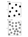
低濃度インクを用いた画像形成方法における画質向上の原理について図6(a),(b)を参照して説明する。図6(a),(b)はそれぞれ画像の低濃度部の拡大図であり、両者の濃度は一致している。図6(a)に示すように、従来からある高濃度インクで表現した従来方式による画像の低濃度部は、ドットを小さく形成するのには限界があるため各ドット相互のドット間距離が広くならざるを得ず、見た目には粗い画像になっていた。
一方、図6(b)に示すように、低濃度インクを用いた画像形成方法では、従来方式と同じ濃度を表現しようとすると単位面積当たりのドットの個数が多くなるため、各ドット相互のドット間距離が近づくことにより見た目にきめの細かい良好な画像を得ることができる。ただし、低濃度インクのみを使用すると、画像の高濃度部において画像濃度を確保するためには多量のインクが必要となるため、従来のような高濃度インクも併用して濃度を補うことで低濃度インクの使用量を抑えていた。
【0005】
ところで、電子写真方式の画像出力機器においても、低濃度トナーと高濃度トナーを用いて上述したような画像の濃度表現方法が可能である。すなわち、画像の低濃度部を表現する場合、低濃度トナーを用いてドット間距離を近くすることによりきめの細かい良好な画像を得ることができる。また、ドット間距離を近づけない場合は、電子写真方式のドットは複数のトナーの集合であるため、低濃度トナーを使用すると、同濃度を表現するためにはドット内のトナーの個数が多くなるため再現のばらつきが画像上で減少することになり、がさつき感のないなめらかな画像が得られる。一方、低濃度トナーのみを使用すると、画像の高濃度部には多量のトナーが必要となり、転写や定着などのプロセスの許容量を越えてしまうため、インクジェット方式の場合と同様に、画像の高濃度部では高濃度トナーを用いて濃度を補うことでトナー使用量の抑制と画像濃度の確保が可能になる。このように、低濃度トナーと高濃度トナーを用いた電子写真方式の画像出力機器では、画像の低濃度部には主に低濃度トナーを優先的に使用し、画像の高濃度部には高濃度トナーを優先的に使用することが好ましい。
【0006】
【発明が解決しようとする課題】
しかしながら、例えばシアン、薄色シアン、マゼンタ、薄色マゼンタ、イエロー、ブラックの6種類のトナーを用いて画像形成を行おうとすると、単純には各色のトナーにそれぞれ対応した6つの現像装置を設ける必要があるため、コスト高と装置の大型化という問題がある。それに加えて、中間転写方式や転写ドラム方式の場合、6サイクルの潜像形成及び現像を行う必要があるため、画像形成に要する時間が長くなりプリント性能が低下するという問題もある。また、タンデム方式の場合は、各色トナーを収容した現像装置に対応する数の感光体が必要となるため、さらにコスト高になり装置が大型化してしまう。
【0007】
そこで、本発明の目的は、低濃度トナーと高濃度トナーを用いて低濃度画像部における画質の向上と、高濃度画像部におけるトナー付着量の抑制および画像濃度の確保とを同時に図りながら印刷スピードの低下をもたらさない画像形成装置及び画像形成方法を提供することにある。
【0008】
【課題を解決するための手段】
上記目的を達成するため、第1の発明の画像形成装置は、表面が均一電位に帯電される像担持体と、
この像担持体の表面に、電位減衰の小さい低濃度部と電位減衰の大きい高濃度部とを含む静電潜像を形成する露光装置と、
上記像担持体表面の静電潜像を現像バイアス電位が印加された現像剤担持体上に保持された現像剤で現像する現像装置と、を備え、
上記現像剤は同一色相でかつ異なる濃度の少なくとも2種類の現像剤を混合してなる混合現像剤であって高濃度現像剤を低濃度現像剤よりも多く混合してあり、上記低濃度現像剤の帯電量を上記高濃度現像剤の帯電量よりも低くするか、又は上記低濃度現像剤の粒形状を上記高濃度現像剤の粒形状よりも球形化してあることを特徴とする。
【0009】
また、第2の発明の画像形成装置は、表面が均一電位に帯電される像担持体と、
この像担持体の表面に、電位減衰の小さい低濃度部と電位減衰の大きい高濃度部とを含む静電潜像を形成する露光装置と、
上記像担持体表面の静電潜像を現像バイアス電位が印加された現像剤担持体上に保持された現像剤で現像する現像装置と、を備え、
上記現像剤は同一色相でかつ異なる濃度の少なくとも2種類の現像剤を混合してなる混合現像剤であって高濃度現像剤を低濃度現像剤よりも多く混合してあり、上記現像剤担持体を磁性材料で形成すると共に上記低濃度現像剤に添加する磁性粉量を上記高濃度現像剤に添加する磁性粉量よりも少なくしてあることを特徴とする。
【0010】
【発明の効果】
第1の発明の画像形成装置では、低濃度現像剤よりも高濃度現像剤を多く混合した混合現像剤を用いているので、静電潜像の高濃度部に付着する現像剤の割合は高濃度現像剤の方が低濃度現像剤より必然的に多くなる。これにより、画像の高濃度部の濃度を確保できると共に、低濃度現像剤だけを付着させて濃度を確保する場合に比べて現像剤付着量を抑制できる。
【0011】
また、低濃度現像剤の帯電量を高濃度現像剤の帯電量よりも低くするか又は低濃度現像剤の粒形状を高濃度現像剤の粒形状よりも球形化してあることで、現像剤担持体に対する低濃度現像剤の付着力が高濃度現像剤のそれよりも比較的小さくなるため、低濃度現像剤の方が現像に供されやすくなる。さらに、現像バイアス電位が印加された現像剤担持体と静電潜像との間の電位ギャップは、電位減衰の小さい低濃度部の方が電位減衰の大きい高濃度部よりも小さくなる。そのため、低電位ギャップとなる低濃度部には、現像に供されやすくなっている低濃度現像剤が優先的に付着する。これにより、低濃度画像部は見た目にきめの細かいなめらかな画像となり、低濃度画像部の画質向上を図れる。
【0012】
さらにまた、現像装置には低濃度現像剤と高濃度現像剤とが混合された混合現像剤が収容されており、かつ静電潜像の低濃度部及び高濃度部は一度の現像工程で混合現像剤により同時に現像されるため、低濃度現像剤と高濃度現像剤について別々の現像装置を設ける必要がなく、しかも、低濃度現像剤による現像工程と高濃度現像剤による現像工程とを分ける必要がない。したがって、従来の電子写真方式のカラー画像形成装置に比べても現像装置や現像工程が増えることがなく、装置が大型化したり、あるいは、一枚の用紙の画像形成時間が長くなるためにプリント性能が低下するといった問題もない。
【0013】
第2の発明の画像形成装置についても同様に、低濃度現像剤よりも高濃度現像剤を多く混合した混合現像剤を用いているので、静電潜像の高濃度部に付着する現像剤の割合は高濃度現像剤の方が低濃度現像剤より必然的に多くなる。これにより、画像の高濃度部の濃度を確保できると共に、低濃度現像剤だけを付着させて濃度を確保する場合に比べて現像剤付着量を抑制できる。
【0014】
また、現像剤担持体を磁性材料で形成すると共に低濃度現像剤に添加する磁性粉量を高濃度現像剤に添加する磁性粉量よりも少なくしてあることで、現像剤担持体に対する低濃度現像剤の付着力が高濃度現像剤のそれよりも比較的小さくなるため、低濃度現像剤の方が現像に供されやすくなる。さらに、現像バイアス電位が印加された現像剤担持体と静電潜像との間の電位ギャップは、電位減衰の小さい低濃度部の方が電位減衰の大きい高濃度部よりも小さくなる。そのため、低電位ギャップとなる低濃度部には、現像に供されやすくなっている低濃度現像剤が優先的に付着する。これにより、低濃度画像部は見た目にきめの細かいなめらかな画像となり、低濃度画像部の画質向上を図れる。
【0015】
さらにまた、現像装置には低濃度現像剤と高濃度現像剤とが混合された混合現像剤が収容されており、かつ静電潜像の低濃度部及び高濃度部は一度の現像工程で混合現像剤により同時に現像されるため、低濃度現像剤と高濃度現像剤について別々の現像装置を設ける必要がなく、しかも、低濃度現像剤による現像工程と高濃度現像剤による現像工程とを分ける必要がない。したがって、従来の電子写真方式のカラー画像形成装置に比べても現像装置や現像工程が増えることがなく、装置が大型化したり、あるいは、一枚の用紙の画像形成時間が長くなるためにプリント性能が低下するといった問題もない。
【0016】
【発明の実施の形態】
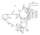
以下、本発明の実施の形態について添付図面を参照して説明する。図1は、本実施形態の画像形成装置10の主要部を概略的に示したものである。この画像形成装置10は、矢印a方向に回転駆動される感光体ドラム(像担持体)12を備えている。感光体ドラム12の周囲には、その回転方向に沿って順に、帯電装置14、露光装置16、4つの現像装置18,20,22,24及び転写装置26が配置されている。現像装置18は現像ローラ19を備えており、現像装置18に収用されたシアントナー(現像剤)が回転する現像ローラ19の外周面上に保持されて感光体ドラム12の対向部に搬送されるようになっている。現像装置20,22,24についても同様に、現像ローラ21,23,25をそれぞれ備えており、各現像装置20,22,24にそれぞれ収用されたマゼンタトナー(現像剤)、イエロートナー(現像剤)、ブラックトナー(現像剤)が回転する各現像ローラ21,23,25の外周面上に保持されて感光体ドラム12の対向部にそれぞれ搬送されるようになっている。また、各現像装置18,20,22,24の現像ローラ19,21,23,25には現像バイアス電位VBがそれぞれ印加されている。
【0017】
転写装置26は、矢印b方向に回転駆動される駆動ローラ28と4つの支持ローラ30,32,34,36との周囲に掛け渡された無端状の中間転写ベルト38を有している。中間転写ベルト38は、ポリカーボネート等の樹脂シート材で形成され、105〜1012(Ω/cm2)程度の表面電気抵抗になるようにカーボンブラックが分散されている。また、中間転写ベルト34は、駆動ローラ28によって駆動されて矢印c方向に回転移動する。さらに、中間転写ベルト38のうち2つの支持ローラ30,32の間に位置する部分は、感光体ドラム12に接触して一次転写領域40を形成している。なお、4つの支持ローラ30,32,34,36は、中間転写ベルト38の移動に伴って従動回転するのが好ましいが、従動回転しない固定式のものであってもよい。
【0018】
一方、支持ローラ36の下方には、矢印d方向に回転駆動される転写ローラ42が配置されている。転写ローラ42は例えばシリコンやウレタンなどの発泡ゴム材で形成され、105〜1012(Ω/cm2)の表面電気抵抗を有するようにカーボンブラックが分散されている。転写ローラ42と支持ローラ36との間にある中間転写ベルト38の領域が二次転写領域44となっている。用紙等の被転写材46は、それぞれ回転する中間転写ベルト38と転写ローラ42との間を通過して矢印e方向に搬送される。
【0019】
上記画像形成装置10では、感光体ドラム12の表面が帯電装置14により均一電位に帯電される。その均一帯電した感光体ドラム12の表面に、露光装置16から画像情報に応じてレーザビーム16aが照射される。これにより、レーザ照射部の電位が減衰して感光体ドラム12の表面にシアン用静電潜像が形成される。この静電潜像が感光体ドラム12の回転にしたがって現像装置18の対向部にくると、現像装置18の現像ローラ19上のシアントナーが静電潜像部に静電的に付着して現像され、感光体ドラム12の表面にシアントナー像が形成される。このシアントナー像が感光体ドラム12の回転にしたがって一次転写領域40に移動し、そこでシアントナー像が中間転写ベルト38に一次転写される。続いて、現像装置20により感光体ドラム12上に同様にして形成されたマゼンタトナー像が一次転写領域40において中間転写ベルト38上のシアントナー像の上に重ねて一次転写される。続いて、同様にして現像装置22,24により感光体ドラム12上にそれぞれ形成されたイエロートナー像及びブラックトナー像が一次転写領域40において中間転写ベルト38上のシアントナー像及びマゼンタトナー像の上に順次重ねて一次転写される。このようにして、中間転写ベルト38上にカラートナー像が形成される。
【0020】
中間転写ベルト38上に形成されたカラートナー像が、中間転写ベルト38の回転にしたがって二次転写領域44に移動してくると、この移動に同期して二次転写領域44に搬送されてきた被転写材46上にカラートナー像が二次転写される。被転写材46に転写されたカラートナー像は、被転写材46が図示しない定着装置を通過する際に定着される。
【0021】
次に、感光体ドラム12上における静電潜像及びトナー像の形成について詳述する。
カラー画像形成工程において感光体ドラム12上には、まず、露光装置16によりシアントナー像用の静電潜像が形成される。画像形成装置10において画像濃度は、周期的に配列されたドットの大きさやラインの幅を増減するディザ法もしくはパルス幅変調方式により表現される。このような画像濃度表現方式により感光体ドラム12上に形成される静電潜像には低濃度部と高濃度部とが含まれている。具体的には、露光装置16から照射されるレーザビーム16aは発光強度に広がり(例えば、半値幅で60μm程度)をもっているため、均一電位に帯電した感光体ドラム12に対するレーザの連続発光時間が短いと電位減衰の小さい(電位減衰が飽和レベルにまで達しない)低濃度部が形成され、レーザ連続発光時間が長いと光量が加算されて電位減衰の大きい(電位減衰が飽和レベルまで達している)高濃度部が形成される。このように形成された低濃度部と高濃度部とを含む静電潜像が、シアントナーを収用した現像装置18により現像される。
【0022】
現像装置18に収用されているシアントナーは、同一色相でかつ異なる濃度の2種類のトナー、すなわち高濃度シアントナーと低濃度シアントナーとが混合された混合トナーであり、かつ高濃度シアントナーの分量が低濃度シアントナーよりも多く混合されている。これにより、現像ローラ19上に保持された混合トナーが一様に現像に供された場合には、感光体ドラム12上に付着するトナーのうち高濃度シアントナーの占める割合が多くなる。
また、低濃度シアントナーの帯電量を高濃度シアントナーの帯電量よりも低くするか、又は低濃度シアントナーの粒形状を高濃度シアントナーの粒形状よりも球形化してある。これにより、現像ローラ19に対する付着力は、低濃度シアントナーの方が高濃度シアントナーよりも比較的小さくなるため、低濃度シアントナーの方が現像ローラ19から離れやすく現像に供されやすくなっている。
【0023】
ここで、図2に高濃度シアントナーと低濃度シアントナーのそれぞれの現像特性を示す。図2のグラフは、現像バイアス電位VBが印加された現像ローラ19と、感光体ドラム12上の静電潜像との間の現像電位ギャップと、感光体ドラム12上に付着するトナー量である現像量との関係を示している。高濃度シアントナーの現像特性は、グラフ中(イ)で示されるように、電位ギャップΔV2までは電位ギャップが大きくなるにつれて現像量が増加する。
一方、グラフ中(ロ)で示される現像特性の低濃度度シアントナーは、上述したように現像ローラ19との付着力が比較的小さくなっているために、ある大きさの電位ギャップΔV1までは高濃度シアントナーよりも現像量が多く、かつ電位ギャップが大きくなるにつれて現像量が増加するが、ΔV1以上に電位ギャップが大きくなっても、すでに現像ローラ19上の低濃度シアントナーはすべて現像に供されてしまっているため、感光体ドラム12上への現像量は飽和して変わらなくなる。
【0024】
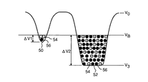
このような現像特性を有する2種類のシアントナーによって感光体ドラム12上の静電潜像が現像される様子を図3を参照して説明する。図3は、静電潜像を構成する低濃度部50と高濃度部52の電位状態とトナー付着状態を示す。低濃度部50の電位は、電位減衰の飽和点であるV3まで達しておらず、感光体ドラム12の帯電電位であるV0と上記V3の中間ぐらいになっている。これに対し、高濃度部52の電位は、電位減衰の飽和点であるV3に達している。
【0025】
このような電位状態にある低濃度部50と高濃度部52に、現像ローラ19上に保持されたトナーが付着して現像されることになるが、図3に示すように、現像バイアス電位がVBの現像ローラ19と低濃度部50及び高濃度部52の電位ギャップはそれぞれΔV1,ΔV2となっている。図2に示したように、電位ギャップΔV1の低濃度部50には低濃度シアントナー54の方が高濃度シアントナー56よりも多く付着する一方、電位ギャップΔV2である高濃度部52には高濃度シアントナー56の方が低濃度シアントナー54よりも多く付着する。ただし、高濃度部52に低濃度シアントナー54がある程度付着することは避けられないので、高濃度部52においても従来と同一付着量で同一の画像濃度を得るためには、高濃度シアントナーを従来のものよりもさらに高濃度化する必要がある。
【0026】
このようにして感光体ドラム12上において静電潜像の低濃度部50に低濃度シアントナー54を優先的に付着させ、かつ高濃度部52に高濃度シアントナー56をより多く付着させたシアントナー像を得ることができる。感光体ドラム12上に形成されたシアントナー像は、一次転写領域40において中間転写ベルト38に転写される。
【0027】
続いて、感光体ドラム12上に形成されるマゼンタトナー像についても同様に、現像装置16には低濃度マゼンタトナーと高濃度マゼンタトナーとが混合して収用されており、この混合トナーによりマゼンタトナー像が形成され、中間転写ベルト38上のシアントナー像の上に転写される。続いて、従来方式によりそれぞれ一種類のイエロートナー及びブラックトナーによって形成されたイエロートナー像とブラックトナー像が中間転写ベルト38上のシアントナー像及びマゼンタトナー像の上に順次転写され、これによりカラートナー像が形成される。
【0028】
以上に説明したように、本実施形態の画像形成装置10によれば、シアントナー及びマゼンタトナーについては、低濃度トナーと高濃度トナーとを混合した混合トナーを用い、かつ低濃度トナーよりも高濃度トナーを多く混合しているので、静電潜像の高濃度部に付着するトナーの割合は高濃度トナーの方が低濃度トナーより当然に多くなる。これにより、画像の高濃度部の濃度を確保できると共に、低濃度トナーだけを付着させて濃度を確保する場合に比べてトナー付着量を抑制できる。
【0029】
また、低濃度トナーの帯電量を高濃度トナーの帯電量よりも低くするか又は低濃度トナーの粒形状を高濃度トナーの粒形状よりも球形化してあることで、現像ローラ19,21に対する低濃度トナーの付着力が高濃度トナーのそれよりも比較的小さくなるため、低濃度トナーの方が現像に供されやすくなる。さらに、現像バイアス電位VBが印加された現像ローラ19,21と静電潜像との間の電位ギャップは、感光体ドラム12の帯電電位からの電位減衰が小さい低濃度部50の方が電位減衰の大きい高濃度部52よりも小さい。そのため、低電位ギャップとなる低濃度部50には、現像に供されやすくなっている低濃度トナー54が優先的に付着する。これにより、低濃度画像部は見た目にきめの細かいなめらかな画像となり、低濃度画像部の画質向上を図れる。
【0030】
さらにまた、現像装置18,20には低濃度トナーと高濃度トナーとが混合された混合トナーが収容されており、かつ静電潜像の低濃度部50及び高濃度部52は一度の現像工程で混合トナーにより同時に現像されるため、低濃度トナーと高濃度トナーについて別々の現像装置を設ける必要がなく、しかも、低濃度トナーによる現像工程と高濃度トナーによる現像工程とを分ける必要がない。したがって、従来の電子写真方式のカラー画像形成装置に比べても現像装置や現像工程が増えることがなく、装置が大型化したり、あるいは、一枚の用紙の画像形成時間が長くなるためにプリント性能が低下するといった問題もない。
【0031】
ところで、上記画像形成装置10では、シアントナー及びマゼンタトナーについて、低濃度トナーの帯電量を高濃度トナーの帯電量よりも低くするか、又は低濃度シアントナーの粒形状を高濃度シアントナーの粒形状よりも球形化することにより、低濃度トナーの現像ローラに対する付着力を比較的小さくして現像に供されやすくなるようにしたが、同様の効果を得るための別の方法として、高濃度トナーを低濃度トナーよりも多く混合し、かつ、現像ローラを磁性材料で形成すると共に低濃度トナーに添加する磁性粉量を高濃度トナーに添加する磁性粉量よりも少なくしてもよい。この場合、高濃度トナーの方が低濃度トナーよりも現像ローラとの間の磁力により強く保持されるため、低電位ギャップとなる静電潜像の低濃度部については低濃度トナーが優先的に付着し、高電位ギャップとなる静電潜像の高濃度部には高濃度トナーがより多く付着する。
【0032】
この場合の高濃度トナー及び低濃度トナーの現像特性を図4のグラフに示し、静電潜像の低濃度部と高濃度部へのトナーの付着状態を図5に示す。図4のグラフ中(イ)で示される高濃度トナーは、現像電位ギャップがΔV1より小さいときには全く現像に供されず、この電位ギャップ範囲では低濃度トナーだけが現像に供されることになる。したがって、図5に示すように、電位ギャップがΔV1である静電潜像の低濃度部50には、低濃度トナー54だけが付着する。一方、図4のグラフ中(ロ)で示される低濃度トナーは、現像電位ギャップがΔV2になったときにはすでに飽和して現像量が一定となっているため、このときには高濃度トナーの方がより多く現像に供されることになる。したがって、図5に示すように、電位ギャップがΔV2である静電潜像の高濃度部52には、高濃度トナー56がより多く付着する。
【0033】
このように、現像ローラを磁性材料で形成すると共に、高濃度トナーに低濃度トナーより多くの磁性粉を添加することによっても、上記画像形成装置10と同様の効果を奏することができる。
【0034】
なお、本実施形態では高濃度トナーと低濃度トナーの2種類のトナーを混合した混合トナーを使用したが、本発明は高濃度、中濃度、低濃度の3種類のトナーを混合した混合トナーを使用した場合にも適用できる。また、本実施形態ではカラー画像形成装置を例にあげて説明したが、本発明はモノカラー(例えば、ブラック)の画像形成装置にも適用できる。
【図面の簡単な説明】
【図1】 本実施形態の画像形成装置の概略構成図。
【図2】 高濃度トナーおよび低濃度トナーの現像電位ギャップと現像量の関係を示すグラフ。
【図3】 静電潜像の低濃度部および高濃度部の電位状態とトナー付着状態を示す図。
【図4】 現像ローラを磁性材料で形成すると共にトナーに添加する磁性粉の量を変えた場合の、高濃度トナーおよび低濃度トナーの現像電位ギャップと現像量の関係を示すグラフ。
【図5】 現像ローラを磁性材料で形成すると共にトナーに添加する磁性粉の量を変えた場合の、静電潜像の低濃度部および高濃度部の電位状態とトナー付着状態を示す図。
【図6】 従来のインクジェット方式による低濃度画像部の拡大図であって、(a)は通常濃度のインクを使用した場合の拡大図で、(b)は薄色インクを使用した場合の拡大図。
【符号の説明】
10…画像形成装置、12…感光体ドラム(像担持体)、16…露光装置、18,20,22,24…現像装置、19,21,23,25…現像ローラ(現像剤担持体)、50…静電潜像の低濃度部、52…静電潜像の高濃度部、54…低濃度トナー(低濃度現像剤)、56…高濃度トナー(高濃度現像剤)。[0001]
BACKGROUND OF THE INVENTION
The present invention relates to an electrophotographic image forming apparatus such as a copying machine or a printer, and an image forming method .
[0002]
[Prior art]
In recent years, full-color image output devices have been widely put into practical use, and there is an increasing demand for improving image quality for various images such as text, graphics, and photographs.
[0003]
Examples of the full-color image output device include an inkjet method and an electrophotographic method.
Among these, in an inkjet full-color image output device, in recent years, an image forming method using six color inks (yellow, magenta, cyan, black, light magenta, light cyan) using low density ink (photo ink) has been devised. , Mainly to improve the quality of photographic images.
[0004]
The principle of image quality improvement in an image forming method using low density ink will be described with reference to FIGS. FIGS. 6A and 6B are enlarged views of the low density portion of the image, and the densities of both are the same. As shown in FIG. 6 (a), the low-density portion of the conventional image expressed with conventional high-density ink has a limit in forming a small dot, so that the distance between dots is wide. Inevitably, the image looked rough.
On the other hand, as shown in FIG. 6B, in the image forming method using low density ink, the number of dots per unit area increases when trying to express the same density as the conventional method. As the distance becomes shorter, a fine and fine image can be obtained. However, if only low-density ink is used, a large amount of ink is required to ensure image density in the high-density part of the image. The amount of density ink used was reduced.
[0005]
Incidentally, even in an electrophotographic image output device, the above-described image density expression method can be performed using low-density toner and high-density toner. That is, when expressing a low density portion of an image, a fine and fine image can be obtained by using a low density toner and reducing the distance between dots. If the distance between dots is not close, an electrophotographic dot is a collection of a plurality of toners. Therefore, if low density toner is used, the number of toners in the dot increases to express the same density. Therefore, variation in reproduction is reduced on the image, and a smooth image without a feeling of roughness can be obtained. On the other hand, if only low-concentration toner is used, a large amount of toner is required in the high-density area of the image, which exceeds the allowable amount for processes such as transfer and fixing. By supplementing the density with a high density toner in the density area, it is possible to suppress the amount of toner used and ensure the image density. As described above, in an electrophotographic image output device using low density toner and high density toner, low density toner is preferentially used for the low density part of the image, and high density part is used for the high density part of the image. It is preferable to use the density toner preferentially.
[0006]
[Problems to be solved by the invention]
However, for example, when image formation is performed using six types of toners of cyan, light cyan, magenta, light magenta, yellow, and black, it is simply necessary to provide six developing devices corresponding to the respective color toners. Therefore, there are problems of high cost and large equipment. In addition, in the case of the intermediate transfer system and the transfer drum system, since it is necessary to perform latent image formation and development of 6 cycles, there is a problem that the time required for image formation becomes long and print performance is deteriorated. In the case of the tandem system, the number of photoconductors corresponding to the developing device containing each color toner is necessary, which further increases the cost and the size of the device.
[0007]
Accordingly, an object of the present invention is to improve the image quality in the low density image area by using the low density toner and the high density toner, suppress the toner adhesion amount in the high density image area, and ensure the image density, while simultaneously achieving the printing speed. It is an object of the present invention to provide an image forming apparatus and an image forming method that do not cause a decrease in image quality.
[0008]
[Means for Solving the Problems]
In order to achieve the above object, an image forming apparatus according to a first aspect of the present invention includes an image carrier whose surface is charged to a uniform potential,
An exposure apparatus that forms an electrostatic latent image on the surface of the image carrier including a low-density portion with a small potential decay and a high-density portion with a large potential decay;
A developing device that develops the electrostatic latent image on the surface of the image carrier with a developer held on the developer carrier to which a developing bias potential is applied, and
The developer is a mixed developer obtained by mixing at least two kinds of developers having the same hue and different concentrations, and a higher concentration developer is mixed than a low concentration developer, and the low concentration developer The charge amount is lower than the charge amount of the high-concentration developer, or the particle shape of the low-concentration developer is made more spherical than the particle shape of the high-concentration developer.
[0009]
An image forming apparatus according to a second aspect of the invention includes an image carrier whose surface is charged to a uniform potential,
An exposure apparatus that forms an electrostatic latent image on the surface of the image carrier including a low-density portion with a small potential decay and a high-density portion with a large potential decay;
A developing device that develops the electrostatic latent image on the surface of the image carrier with a developer held on the developer carrier to which a developing bias potential is applied, and
The developer is a mixed developer obtained by mixing at least two kinds of developers having the same hue and different concentrations, and a higher concentration developer is mixed than a low concentration developer, and the developer carrier Is formed of a magnetic material, and the amount of magnetic powder added to the low concentration developer is smaller than the amount of magnetic powder added to the high concentration developer.
[0010]
【The invention's effect】
In the image forming apparatus according to the first aspect of the invention, since the mixed developer in which the high density developer is mixed more than the low density developer is used, the ratio of the developer adhering to the high density portion of the electrostatic latent image is high. The density developer is inevitably higher than the low density developer. As a result, the density of the high density portion of the image can be ensured, and the amount of developer adhesion can be suppressed as compared with the case where only the low density developer is adhered to ensure the density.
[0011]
Also, the developer carrying amount is reduced by making the charge amount of the low concentration developer lower than the charge amount of the high concentration developer or making the particle shape of the low concentration developer spherical than the particle shape of the high concentration developer. Since the adhesion of the low density developer to the body is relatively smaller than that of the high density developer, the low density developer is more likely to be used for development. Further, the potential gap between the developer bearing member to which the developing bias potential is applied and the electrostatic latent image is smaller in the low density portion where the potential attenuation is small than in the high density portion where the potential attenuation is large. Therefore, a low-concentration developer that is likely to be used for development is preferentially attached to the low-density portion that becomes the low potential gap. As a result, the low-density image portion becomes a smooth and fine image, and the image quality of the low-density image portion can be improved.
[0012]
Furthermore, the developing device contains a mixed developer in which a low density developer and a high density developer are mixed, and the low density part and the high density part of the electrostatic latent image are mixed in a single development process. Since development is performed simultaneously with the developer, there is no need to provide separate developing devices for the low-concentration developer and the high-concentration developer, and the development process using the low-concentration developer and the development process using the high-concentration developer need to be separated. There is no. Therefore, there is no increase in the number of developing devices and development processes compared to conventional electrophotographic color image forming apparatuses, and the size of the apparatus is increased, or the image forming time of one sheet is increased, so that the printing performance is increased. There is also no problem of lowering.
[0013]
Similarly, the image forming apparatus of the second invention uses a mixed developer in which a higher concentration developer is mixed than a low concentration developer, so that the developer adhering to the high density portion of the electrostatic latent image can be reduced. The proportion is necessarily higher for high density developers than for low density developers. As a result, the density of the high density portion of the image can be ensured, and the amount of developer adhesion can be suppressed as compared with the case where only the low density developer is adhered to ensure the density.
[0014]
In addition, the developer carrier is formed of a magnetic material and the amount of magnetic powder added to the low-concentration developer is smaller than the amount of magnetic powder added to the high-concentration developer. Since the adhesive force of the developer is relatively smaller than that of the high density developer, the low density developer is more likely to be used for development. Further, the potential gap between the developer bearing member to which the developing bias potential is applied and the electrostatic latent image is smaller in the low density portion where the potential attenuation is small than in the high density portion where the potential attenuation is large. Therefore, a low-concentration developer that is likely to be used for development is preferentially attached to the low-density portion that becomes the low potential gap. As a result, the low-density image portion becomes a smooth and fine image, and the image quality of the low-density image portion can be improved.
[0015]
Furthermore, the developing device contains a mixed developer in which a low density developer and a high density developer are mixed, and the low density part and the high density part of the electrostatic latent image are mixed in a single development process. Since development is performed simultaneously with the developer, there is no need to provide separate developing devices for the low-concentration developer and the high-concentration developer, and the development process using the low-concentration developer and the development process using the high-concentration developer need to be separated. There is no. Therefore, there is no increase in the number of developing devices and development processes compared to conventional electrophotographic color image forming apparatuses, and the size of the apparatus is increased, or the image forming time of one sheet is increased, so that the printing performance is increased. There is also no problem of lowering.
[0016]
DETAILED DESCRIPTION OF THE INVENTION
Embodiments of the present invention will be described below with reference to the accompanying drawings. FIG. 1 schematically shows a main part of an
[0017]
The
[0018]
On the other hand, a transfer roller 42 that is rotationally driven in the direction of the arrow d is disposed below the
[0019]
In the
[0020]
When the color toner image formed on the
[0021]
Next, the formation of the electrostatic latent image and the toner image on the photosensitive drum 12 will be described in detail.
In the color image forming process, an electrostatic latent image for a cyan toner image is first formed on the photosensitive drum 12 by the
[0022]
The cyan toner collected in the developing
Further, the charge amount of the low density cyan toner is made lower than the charge amount of the high density cyan toner, or the particle shape of the low density cyan toner is made more spherical than the particle shape of the high density cyan toner. As a result, the low-density cyan toner is relatively smaller in the adhesion force to the developing roller 19 than the high-density cyan toner, so that the low-density cyan toner is more easily separated from the developing roller 19 and more easily used for development. Yes.
[0023]
FIG. 2 shows the development characteristics of the high density cyan toner and the low density cyan toner. The graph of FIG. 2 shows the development potential gap between the developing roller 19 to which the development bias potential V B is applied and the electrostatic latent image on the photosensitive drum 12 and the amount of toner adhering to the photosensitive drum 12. The relationship with a certain development amount is shown. As shown in (a) of the graph, the development characteristics of the high-density cyan toner increase as the potential gap increases until the potential gap ΔV2.
On the other hand, the low-density cyan toner having the development characteristics indicated by (B) in the graph has a relatively small adhesive force with the developing roller 19 as described above, and therefore, until the potential gap ΔV1 of a certain size is reached. Although the development amount increases as the potential gap becomes larger than the high density cyan toner and the potential gap becomes larger, all the low density cyan toner on the developing roller 19 has already been developed even if the potential gap becomes larger than ΔV1. Since it has been provided, the development amount on the photosensitive drum 12 is saturated and does not change.
[0024]
The manner in which the electrostatic latent image on the photosensitive drum 12 is developed by the two types of cyan toner having such development characteristics will be described with reference to FIG. FIG. 3 shows the potential state and toner adhesion state of the
[0025]
The toner held on the developing roller 19 adheres to the
[0026]
In this way, cyan on which the low
[0027]
Subsequently, for the magenta toner image formed on the photosensitive drum 12, similarly, a low density magenta toner and a high density magenta toner are mixed and collected in the developing
[0028]
As described above, according to the
[0029]
Further, the charge amount of the low density toner is made lower than the charge amount of the high density toner, or the particle shape of the low density toner is made more spherical than the particle shape of the high density toner. Since the adhesion force of the density toner is relatively smaller than that of the high density toner, the low density toner is more likely to be used for development. Further, the potential gap between the developing rollers 19 and 21 to which the developing bias potential V B is applied and the electrostatic latent image is lower in the
[0030]
Furthermore, the developing
[0031]
By the way, in the
[0032]
The development characteristics of the high density toner and the low density toner in this case are shown in the graph of FIG. 4, and the adhesion state of the toner to the low density part and the high density part of the electrostatic latent image is shown in FIG. The high density toner indicated by (A) in the graph of FIG. 4 is not used for development when the development potential gap is smaller than ΔV1, and only the low density toner is used for development in this potential gap range. Therefore, as shown in FIG. 5, only the
[0033]
Thus, the same effect as that of the
[0034]
In this embodiment, a mixed toner obtained by mixing two types of toners, a high density toner and a low density toner, is used. However, the present invention uses a mixed toner obtained by mixing three kinds of toners of high density, medium density, and low density. It can also be applied when used. In the present embodiment, a color image forming apparatus has been described as an example. However, the present invention can also be applied to a monocolor (for example, black) image forming apparatus.
[Brief description of the drawings]
FIG. 1 is a schematic configuration diagram of an image forming apparatus according to an embodiment.
FIG. 2 is a graph showing a relationship between a development potential gap and a development amount of high density toner and low density toner.
FIG. 3 is a diagram illustrating a potential state and a toner adhesion state in a low density portion and a high density portion of an electrostatic latent image.
FIG. 4 is a graph showing the relationship between the development potential gap and the development amount of high-concentration toner and low-concentration toner when the developing roller is formed of a magnetic material and the amount of magnetic powder added to the toner is changed.
FIG. 5 is a diagram illustrating a potential state and a toner adhesion state of a low density portion and a high density portion of an electrostatic latent image when the developing roller is formed of a magnetic material and the amount of magnetic powder added to the toner is changed.
FIGS. 6A and 6B are enlarged views of a low-density image portion according to a conventional inkjet method, in which FIG. 6A is an enlarged view when ink of normal density is used, and FIG. 6B is an enlarged view when light-color ink is used. Figure.
[Explanation of symbols]
DESCRIPTION OF
Claims (6)
この像担持体の表面に、電位減衰の小さい低濃度部と電位減衰の大きい高濃度部とを含む静電潜像を形成する露光装置と、
上記像担持体表面の静電潜像を現像バイアス電位が印加された現像剤担持体上に保持された現像剤で現像する現像装置と、を備え、
上記現像剤は同一色相でかつ異なる濃度の少なくとも2種類の現像剤を混合してなる混合現像剤であって高濃度現像剤を低濃度現像剤よりも多く混合してあり、上記低濃度現像剤の帯電量を上記高濃度現像剤の帯電量よりも低くするか、又は上記低濃度現像剤の粒形状を上記高濃度現像剤の粒形状よりも球形化してあることを特徴とする画像形成装置。An image carrier whose surface is charged to a uniform potential;
An exposure apparatus that forms an electrostatic latent image on the surface of the image carrier including a low-density portion with a small potential attenuation and a high-density portion with a large potential decay;
A developing device for developing the electrostatic latent image on the surface of the image carrier with a developer held on the developer carrier to which a development bias potential is applied, and
The developer is a mixed developer obtained by mixing at least two kinds of developers having the same hue and different concentrations, and the high concentration developer is mixed more than the low concentration developer, and the low concentration developer The image forming apparatus is characterized in that the charge amount of the low-concentration developer is made lower than the charge amount of the high-concentration developer, or the particle shape of the low-concentration developer is made more spherical than the particle shape of the high-concentration developer. .
この像担持体の表面に、電位減衰の小さい低濃度部と電位減衰の大きい高濃度部とを含む静電潜像を形成する露光装置と、
上記像担持体表面の静電潜像を現像バイアス電位が印加された現像剤担持体上に保持された現像剤で現像する現像装置と、を備え、
上記現像剤は同一色相でかつ異なる濃度の少なくとも2種類の現像剤を混合してなる混合現像剤であって高濃度現像剤を低濃度現像剤よりも多く混合してあり、上記現像剤担持体を磁性材料で形成すると共に上記低濃度現像剤に添加する磁性粉量を上記高濃度現像剤に添加する磁性粉量よりも少なくしてあることを特徴とする画像形成装置。An image carrier whose surface is charged to a uniform potential;
An exposure apparatus that forms an electrostatic latent image on the surface of the image carrier including a low-density portion with a small potential decay and a high-density portion with a large potential decay;
A developing device that develops the electrostatic latent image on the surface of the image carrier with a developer held on the developer carrier to which a developing bias potential is applied, and
The developer is a mixed developer obtained by mixing at least two kinds of developers having the same hue and different concentrations, and a higher concentration developer is mixed than a low concentration developer, and the developer carrier An image forming apparatus wherein the amount of magnetic powder added to the low-concentration developer is smaller than the amount of magnetic powder added to the high-concentration developer.
この像担持体の表面を露光することにより、低濃度部と高濃度部とを含む静電潜像を形成する露光工程と、An exposure step of forming an electrostatic latent image including a low density portion and a high density portion by exposing the surface of the image carrier;
上記像担持体表面の静電潜像を現像バイアス電位が印加された現像剤担持体上に保持された現像剤で現像する現像工程とを含み、Developing the electrostatic latent image on the surface of the image carrier with a developer held on the developer carrier to which a development bias potential is applied,
上記現像剤が同一色相でかつ異なる濃度の少なくとも2種類の現像剤を混合してなる混合現像剤であって、高濃度現像剤を低濃度現像剤よりも多く混合してあり、低濃度現像剤が高濃度現像剤よりも現像剤担持体から離れやすいことを特徴とする画像形成方法。The developer is a mixed developer formed by mixing at least two types of developers having the same hue and different concentrations, and a high concentration developer is mixed more than a low concentration developer. Is more easily separated from the developer carrier than the high-density developer.
Priority Applications (1)
| Application Number | Priority Date | Filing Date | Title |
|---|---|---|---|
| JP27120898A JP4103200B2 (en) | 1998-09-25 | 1998-09-25 | Image forming apparatus |
Applications Claiming Priority (1)
| Application Number | Priority Date | Filing Date | Title |
|---|---|---|---|
| JP27120898A JP4103200B2 (en) | 1998-09-25 | 1998-09-25 | Image forming apparatus |
Publications (3)
| Publication Number | Publication Date |
|---|---|
| JP2000098712A JP2000098712A (en) | 2000-04-07 |
| JP2000098712A5 JP2000098712A5 (en) | 2005-04-07 |
| JP4103200B2 true JP4103200B2 (en) | 2008-06-18 |
Family
ID=17496865
Family Applications (1)
| Application Number | Title | Priority Date | Filing Date |
|---|---|---|---|
| JP27120898A Expired - Fee Related JP4103200B2 (en) | 1998-09-25 | 1998-09-25 | Image forming apparatus |
Country Status (1)
| Country | Link |
|---|---|
| JP (1) | JP4103200B2 (en) |
Families Citing this family (4)
| Publication number | Priority date | Publication date | Assignee | Title |
|---|---|---|---|---|
| US7248805B2 (en) | 2004-08-05 | 2007-07-24 | Konica Minolta Business Technologies, Inc. | Image forming apparatus and developing unit |
| JP4103868B2 (en) | 2004-08-05 | 2008-06-18 | コニカミノルタビジネステクノロジーズ株式会社 | Image forming apparatus and developing apparatus |
| JP6593655B2 (en) * | 2016-11-25 | 2019-10-23 | 京セラドキュメントソリューションズ株式会社 | Image forming apparatus and image forming method |
| JP7032240B2 (en) * | 2018-05-28 | 2022-03-08 | シャープ株式会社 | Developing equipment and image forming equipment |
-
1998
- 1998-09-25 JP JP27120898A patent/JP4103200B2/en not_active Expired - Fee Related
Also Published As
| Publication number | Publication date |
|---|---|
| JP2000098712A (en) | 2000-04-07 |
Similar Documents
| Publication | Publication Date | Title |
|---|---|---|
| US8158313B2 (en) | Image forming apparatus for forming a color image, and image forming method for forming a color image | |
| JP4819424B2 (en) | Image forming apparatus | |
| US8897660B2 (en) | Image forming apparatus and method | |
| US4778740A (en) | Color electrophotographic method and apparatus | |
| JP2009092718A (en) | Image forming apparatus | |
| JP4103200B2 (en) | Image forming apparatus | |
| US7991311B2 (en) | Image forming apparatus and method for controlling developing bias voltage | |
| US5835832A (en) | Optimal toner charge for use with a compliant transfer intermediate | |
| JP2006220800A (en) | Image forming apparatus | |
| JP4019521B2 (en) | Image forming apparatus | |
| CN1896888A (en) | Image forming apparatus for controlling developing unit voltage | |
| US7526235B2 (en) | Image-forming device | |
| US5890045A (en) | Elastic intermediate belt and system particularly for use in electrostatographic printing systems | |
| US9213255B1 (en) | Printing tactile images with improved image quality | |
| JP2004295144A (en) | Image forming apparatus | |
| JPS5915945A (en) | Multicolor printing method | |
| JP3306667B2 (en) | Color recording device | |
| JP2002182456A (en) | Image forming device | |
| KR100453035B1 (en) | Electrostatically transfering method of liquid electrophotographic printer | |
| JPH07152267A (en) | Image forming device | |
| JPH0731439B2 (en) | Color-Electrophotographic method | |
| JPH05333684A (en) | Recording device | |
| JP2007334271A (en) | Image forming apparatus and image forming method | |
| JP2000330361A (en) | Image forming device | |
| JPH08202166A (en) | Electrophotographic device |
Legal Events
| Date | Code | Title | Description |
|---|---|---|---|
| A521 | Written amendment |
Free format text: JAPANESE INTERMEDIATE CODE: A523 Effective date: 20040519 |
|
| A621 | Written request for application examination |
Free format text: JAPANESE INTERMEDIATE CODE: A621 Effective date: 20040519 |
|
| A711 | Notification of change in applicant |
Free format text: JAPANESE INTERMEDIATE CODE: A712 Effective date: 20040519 |
|
| A521 | Written amendment |
Free format text: JAPANESE INTERMEDIATE CODE: A523 Effective date: 20040524 |
|
| A521 | Written amendment |
Free format text: JAPANESE INTERMEDIATE CODE: A821 Effective date: 20040707 |
|
| RD02 | Notification of acceptance of power of attorney |
Free format text: JAPANESE INTERMEDIATE CODE: A7422 Effective date: 20040707 |
|
| A977 | Report on retrieval |
Free format text: JAPANESE INTERMEDIATE CODE: A971007 Effective date: 20060418 |
|
| A131 | Notification of reasons for refusal |
Free format text: JAPANESE INTERMEDIATE CODE: A131 Effective date: 20060502 |
|
| TRDD | Decision of grant or rejection written | ||
| A01 | Written decision to grant a patent or to grant a registration (utility model) |
Free format text: JAPANESE INTERMEDIATE CODE: A01 Effective date: 20080304 |
|
| A61 | First payment of annual fees (during grant procedure) |
Free format text: JAPANESE INTERMEDIATE CODE: A61 Effective date: 20080317 |
|
| R150 | Certificate of patent or registration of utility model |
Free format text: JAPANESE INTERMEDIATE CODE: R150 |
|
| FPAY | Renewal fee payment (event date is renewal date of database) |
Free format text: PAYMENT UNTIL: 20110404 Year of fee payment: 3 |
|
| FPAY | Renewal fee payment (event date is renewal date of database) |
Free format text: PAYMENT UNTIL: 20120404 Year of fee payment: 4 |
|
| FPAY | Renewal fee payment (event date is renewal date of database) |
Free format text: PAYMENT UNTIL: 20130404 Year of fee payment: 5 |
|
| FPAY | Renewal fee payment (event date is renewal date of database) |
Free format text: PAYMENT UNTIL: 20140404 Year of fee payment: 6 |
|
| LAPS | Cancellation because of no payment of annual fees |