JP4102198B2 - 2D pyramid filter architecture - Google Patents
2D pyramid filter architecture Download PDFInfo
- Publication number
- JP4102198B2 JP4102198B2 JP2002586286A JP2002586286A JP4102198B2 JP 4102198 B2 JP4102198 B2 JP 4102198B2 JP 2002586286 A JP2002586286 A JP 2002586286A JP 2002586286 A JP2002586286 A JP 2002586286A JP 4102198 B2 JP4102198 B2 JP 4102198B2
- Authority
- JP
- Japan
- Prior art keywords
- pyramid
- order
- dimensional
- output signal
- filters
- Prior art date
- Legal status (The legal status is an assumption and is not a legal conclusion. Google has not performed a legal analysis and makes no representation as to the accuracy of the status listed.)
- Expired - Lifetime
Links
Images


Classifications
-
- G—PHYSICS
- G06—COMPUTING; CALCULATING OR COUNTING
- G06T—IMAGE DATA PROCESSING OR GENERATION, IN GENERAL
- G06T1/00—General purpose image data processing
-
- H—ELECTRICITY
- H03—ELECTRONIC CIRCUITRY
- H03H—IMPEDANCE NETWORKS, e.g. RESONANT CIRCUITS; RESONATORS
- H03H17/00—Networks using digital techniques
- H03H17/02—Frequency selective networks
- H03H17/0202—Two or more dimensional filters; Filters for complex signals
Abstract
Description
(関連出願)
本特許出願は、本件で請求した主題の譲受人に譲渡され、参照によりすべて本明細書に組み込まれた、2001年1月3日出願のTinku Acharyaによる「Multiplierless Pyramid Filter」という名称の米国特許出願第09/754684号;2001年3月26日出願のTinku Acharyaによる「Two−Dimensional Pyramid Filter Architecture」という名称の米国特許出願第09/817711号(代理人整理番号042390.P11275);2001年3月28日出願のTinku Acharyaによる「Pyramid Filter」という名称の米国特許出願第09/820108号(代理人整理番号042390.P11211);2001年3月30日出願のTinku Acharyaによる「Two−Dimensional Pyramid Filter Architecture」という名称の米国特許出願第09/823212号(代理人整理番号042390.P11276);2001年3月30日出願のTinku Acharyaによる「Two−Dimensional Pyramid Filter Architecture」という名称の米国特許出願第09/823390号(代理人整理番号042390.P11277)に関する。
(Related application)
This patent application is assigned to the assignee of the subject matter claimed herein and is hereby incorporated by reference in its entirety, US patent application entitled “Multipleless Pyramid Filter” by Tinku Acharya, filed Jan. 3, 2001. No. 09/754684; US Patent Application No. 09/817711 entitled “Two-Dimensional Pyramid Filter Architecture” filed on March 26, 2001 by Tinku Acharya (Attorney Docket No. 0423390.P11275); March 2001 US patent application Ser. No. 09/820108 entitled “Pyramid Filter” by Tinku Acharya filed on 28th (Attorney Docket No. 042390.P11211) US patent application Ser. No. 09/823212 (Attorney Docket No. 0423390.P11276) entitled “Two-Dimensional Pyramid Filter Architecture” by Tinku Acharya, filed March 30, 2001; Tinku Acharya, filed March 30, 2001; In US patent application Ser. No. 09/823390 (Attorney Docket No. 042390.P11277) entitled “Two-Dimensional Pyramid Filter Architecture”.
本発明は、ピラミッド・フィルタに関する。 The present invention relates to pyramid filters.
イメージ処理においては、スキャンされたカラー・イメージなどのイメージを、2つまたはそれ以上の別々のイメージ表現に分解することが好ましい場合が多い。たとえば、カラーまたはグレイ・スケールのドキュメント・イメージは、時折、典型的な写真複写機またはスキャナ・デバイスで適用される場合、強調、圧縮などの効率的なイメージ処理オペレーションのために背景および前景イメージに分解される。このような状況では、このオペレーションはデスクリーニング・オペレーションと呼ばれることが多い。このデスクリーニングは、元のスキャンされたイメージに存在するであろうハーフトーン・パターンを除去するために適用されることもある。たとえば、これらのハーフトーン・パターンは、適切に除去されないと、人間の目に不快なアーティファクトを生じさせる場合がある。この分解またはデスクリーニングのための従来の方法は、カラー・イメージをぼかすためにフィルタリングすることである。こうしてぼかされた結果は、分解するためにイメージをどの程度ぼかしたり鮮明にしたりするかを決定する際の支援として使用される。典型的には、このぼかしは「対称ピラミッド」フィルタを使用して達成することができる。対称ピラミッド有限インパルス応答(FIR)フィルタがよく知られている。 In image processing, it is often desirable to decompose an image, such as a scanned color image, into two or more separate image representations. For example, color or gray scale document images are sometimes applied to background and foreground images for efficient image processing operations such as enhancement, compression, etc. when applied in typical photocopiers or scanner devices. Disassembled. In such situations, this operation is often referred to as a descreening operation. This descreening may be applied to remove halftone patterns that may be present in the original scanned image. For example, these halftone patterns may cause objectionable artifacts to the human eye if not properly removed. The conventional method for this decomposition or descreening is to filter the color image to blur. The result of this blur is used as an aid in determining how much the image will be blurred or sharpened for decomposition. Typically, this blur can be achieved using a “symmetric pyramid” filter. Symmetric pyramid finite impulse response (FIR) filters are well known.
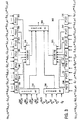
ただし、このイメージ処理技法の欠点の1つは、この技法を前述のように適用する際、複数のぼかされたイメージを生成するためにサイズの異なるいくつかのピラミッド・フィルタが並列に適用されると、複雑さが何倍にも増すことである。この複数のピラミッド・フィルタリング方法のための力まかせの方法が、図1に示されたような複数のFIRフィルタを並列に使用するものである。こうした方法は、単一のソース・イメージから異なるぼかされたイメージを並列に生成するために、高速「対称ピラミッド・フィルタリング」アーキテクチャの設計および実施が望ましいことを実証している。 However, one of the disadvantages of this image processing technique is that when this technique is applied as described above, several pyramid filters of different sizes are applied in parallel to generate multiple blurred images. So the complexity increases many times. The force-running method for this plurality of pyramid filtering methods uses a plurality of FIR filters as shown in FIG. 1 in parallel. Such a method demonstrates the desirability of designing and implementing a fast “symmetric pyramid filtering” architecture to generate different blurred images in parallel from a single source image.
図1で各FIRブロックについて括弧内に与えられた数は、対応する長さのピラミッド・フィルタを表す。たとえば、(1,2,1)は、次数または長さが3の対称ピラミッド有限インパルス応答(FIR)フィルタのフィルタ係数である。同様に、(1,2,3,2,1)は次数5のFIRピラミッド・フィルタの係数である、(1,2,3,4,3,2,1)は次数7のFIRピラミッド・フィルタの係数である、(1,2,3,4,5,4,3,2,1)は次数9のFIRピラミッド・フィルタの係数である、(1,2,3,4,5,6,5,4,3,2,1)は次数11のFIRピラミッド・フィルタの係数である、という具合である。
The number given in parentheses for each FIR block in FIG. 1 represents the corresponding length pyramid filter. For example, (1,2,1) is the filter coefficient of a symmetric pyramid finite impulse response (FIR) filter of
残念ながら、図1で実証された方法には欠点がある。たとえば、計算が冗長であることから効率が悪い場合がある。同様に、FIRの実施には乗算器回路が使用される。シフティングまたは加算回路などを使用して、乗算器の使用を減らすかまたは避けるための実施があるが、その結果クロッキングが増加し、回路のスループットが低下してしまう場合がある。 Unfortunately, the method demonstrated in FIG. 1 has drawbacks. For example, there are cases where the efficiency is poor due to redundant calculations. Similarly, multiplier circuits are used to implement FIR. There are implementations to reduce or avoid the use of multipliers, such as by using shifting or adder circuits, but this may result in increased clocking and reduced circuit throughput.
したがって、ピラミッド・フィルタリングの実施またはアーキテクチャの改善が求められている。 Therefore, there is a need to implement pyramid filtering or improve architecture.
主題は、本明細書の結論部分で具体的に指摘され、明確に請求されている。ただし、オペレーションの構成および方法の両方に関して、その目的、特徴、および付属物と共に請求された主題は、添付の図面と共に読めば、以下の詳細な説明を参照することによって、最もよく理解されよう。 The subject matter is specifically pointed out and distinctly claimed in the concluding portion of the specification. However, the subject matter, features, and claimed subject matter with respect to both the structure and method of operation will be best understood by reference to the following detailed description when read in conjunction with the accompanying drawings.
以下の詳細な説明では、請求された主題を完全に理解するために多数の特定の細部について記述している。ただし当分野の技術者であれば、記載された主題はこれらの特定の細部なしでも実施可能であることを理解されよう。その他の場合、請求された主題を不鮮明にしないように、よく知られた方法、手順、構成要素、および回路については詳細に記載していない。 In the following detailed description, numerous specific details are set forth in order to provide a thorough understanding of claimed subject matter. However, those skilled in the art will appreciate that the described subject matter may be practiced without these specific details. In other instances, well known methods, procedures, components, and circuits have not been described in detail as not to obscure claimed subject matter.
前述のように、ピラミッド・フィルタリング、より具体的には対称ピラミッド・フィルタリングは、イメージを、たとえば背景および前景イメージなどに分解またはデスクリーニングするために、カラー・イメージまたはカラー・イメージ処理と関連して使用することができる。請求された主題の範囲はこの点で限定されるものではないが、こうした状況では、計算の複雑さまたは処理および/またはハードウェアのコストを減らすピラミッド・フィルタリング・アーキテクチャが特に望ましい。同様に、乗算器なしの実施、すなわち実施において具体的に乗算を使用しないことも通常は望ましい。なぜなら、こうした実施または実施形態が乗算器回路を使用するかまたは含むものよりも安価に実施できるからである。 As mentioned above, pyramid filtering, more specifically symmetric pyramid filtering, is associated with color image or color image processing to decompose or descreen images into, for example, background and foreground images. Can be used. Although the scope of the claimed subject matter is not limited in this respect, in such situations, a pyramid filtering architecture that reduces computational complexity or processing and / or hardware costs is particularly desirable. Similarly, it is usually desirable to implement without a multiplier, i.e. not specifically using multiplication in the implementation. This is because such an implementation or embodiment can be implemented cheaper than one that uses or includes a multiplier circuit.
請求の主題はこの点で限定されるものではないが、図2は、前述の2001年1月3日出願のT.Acharyaによる「Multiplierless Pyramid Filter」という名称の米国特許出願第09/754684号(整理番号042390.P10722)でより詳細に記載されているような、1次元ピラミッド・フィルタの実施形態200を示す図である。実施形態200は、様々な次数を有する一連のピラミッド・フィルタまたはピラミッド・フィルタ・シーケンスに対して複数のフィルタリング済み出力信号ストリームを生成し、この出力信号ストリームが並列に生成される、統一された乗算器なし縦続対称ピラミッド・フィルタリング・アーキテクチャを含む。ただしこの特定の実施形態でも、請求された主題の範囲はこの点で限定されるものではなく、フィルタリング済み出力信号ストリームは、実施される異なる次数の各ピラミッド・フィルタに対して、あらゆるクロック・サイクルで生成される。したがってこの特定の実施形態は、計算が効率的であることに加えて、スループットの点でも良い結果を生み出す。ただし以前に示したように、この特定の実施形態は1次元ピラミッド・フィルタを実施する。 Although the claimed subject matter is not limited in this respect, FIG. FIG. 7 shows an embodiment 200 of a one-dimensional pyramid filter, as described in more detail in US patent application Ser. No. 09/754684 (reference number 0423390.P10722) by Acharya entitled “Multiplierless Pyramid Filter”. . Embodiment 200 generates a plurality of filtered output signal streams for a series of pyramid filters or pyramid filter sequences having various orders, wherein the output signal streams are generated in parallel. Includes cascadeless symmetric pyramid filtering architecture. However, even in this particular embodiment, the scope of the claimed subject matter is not limited in this respect, and the filtered output signal stream may be transmitted every clock cycle for each different order pyramid filter implemented. Is generated. This particular embodiment thus produces good results in terms of throughput, in addition to being computationally efficient. However, as previously indicated, this particular embodiment implements a one-dimensional pyramid filter.
図2は、特有の表記法の状況で理解される。たとえば、入力ソース信号Xは、以下のように示すことができる。 FIG. 2 is understood in the context of a specific notation. For example, the input source signal X can be expressed as follows:
![]()
![]()
デジタルまたは離散的信号処理では、フィルタリングを、入力信号Xと、この状況では有限長さのデジタル・フィルタであり本明細書では有限インパルス応答(FIR)フィルタと呼ばれるフィルタFとの、コンボリューション(×)として表すことができる。したがって、フィルタリング済み出力信号ストリームは、以下のように示される。(訳注:(×)は実際は下記の式のように丸の中に「×」を書き入れた記号である。) In digital or discrete signal processing, the filtering is a convolution (××) of the input signal X and a filter F, which in this situation is a finite length digital filter, referred to herein as a finite impulse response (FIR) filter. ). Thus, the filtered output signal stream is shown as follows: (Note: (x) is actually a symbol with "x" in a circle as in the following formula.)
![]()
![]()
前述のように、図2の特定の実施形態はピラミッド・フィルタを使用する。これらのフィルタは、典型的には、3、5、7、9などの奇数の長さまたは次数のデジタル・フィルタを使用して実施される。この状況では、奇数の数または次数は2N−1の形で表すことが可能であり、ここでNはたとえば2よりも大きい正の整数である。こうしたデジタル・フィルタのいくつかの例は、以下のようになる。 As mentioned above, the particular embodiment of FIG. 2 uses a pyramid filter. These filters are typically implemented using odd length or order digital filters such as 3, 5, 7, 9. In this situation, odd numbers or orders can be represented in the form 2N-1, where N is a positive integer greater than 2, for example. Some examples of such digital filters are:

FM=(1,2,3,...,N,...,3,2,1)(このコンテキストではM=2N−1)
F M = (1,2,3, ..., N, ..., 3,2,1) (M = 2N-1 in this context)
上記のフィルタの場合、フィルタリング済み出力信号または出力信号ストリームは、以下のように表すことができる。
B3=X(×)F3=(b0 3,b1 3,...,bi−1 3,bi 3,bi+1 3,...) 入力信号XをF3でフィルタリングした結果
B5=X(×)F5=(b0 5,b1 5,...,bi−1 5,bi 5,bi+1 5,...) 入力信号XをF5でフィルタリングした結果
B7=X(×)F7=(b0 7,b1 7,...,bi−1 7,bi 7,bi+1 7,...) 入力信号XをF7でフィルタリングした結果
B9=X(×)F9=(b0 9,b1 9,...,bi−1 9,bi 9,bi+1 9,...) 入力信号XをF9でフィルタリングした結果
B11=X(×)F11=(b0 11,b1 11,...,bi−1 11,bi 11,bi+1 11,...) 入力信号XをF11でフィルタリングした結果
.....
BM=X(×)FM=(b0 M,b1 M,...,bi−1 M,bi M,bi+1 M,...) 入力信号XをFMでフィルタリングした結果
For the above filter, the filtered output signal or output signal stream can be expressed as:
B 3 = X (×) F 3 = (b 0 3 , b 1 3 ,..., B i−1 3 , b i 3 , b i + 1 3 ,...) The input signal X is filtered by F 3 . Results B 5 = X (×) F 5 = (b 0 5 , b 1 5 ,..., B i−1 5 , b i 5 , b i + 1 5 ,...) Filtering the input signal X with F 5 As a result of B 7 = X (×) F 7 = (b 0 7,
B M = X (×) F M = (b 0 M, b 1 M, ..., b i-1 M, b i M, b i + 1 M, ...) of the input signal X and filtered by F M result
これらのフィルタリング済み出力信号サンプルを経験に基づいて表すための代替方法は、以下のようになる。 An alternative way to represent these filtered output signal samples based on experience is as follows.
同様に、このコンテキストでは状態変数と呼ばれるものを導入することにより、上記の式を以下のように書き直すことができる。
bi 3=xi+si 3 この式で、si 3=xi−1+xi+xi+1
bi 5=bi 3+si 5 この式で、si 5=xi−2+xi−1+xi+xi+1+xi+2
bi 7=bi 5+si 7 この式で、si 7=xi−3+xi−2+xi−1+xi+xi+1+xi+2+xi+3
bi 9=bi 7+si 9 この式で、si 9=xi−4+xi−3+xi−2+xi−1+xi+xi+1+xi+2+xi+3+xi+4
bi 11=bi 9+si 11 この式で、si 11=xi−5+xi−4+xi−3+xi−2+xi−1+xi+xi+1+xi+2+xi+3+xi+4+xi+5
したがって、所望のピラミッド・フィルタは、以下のように表すことができる。
B3=X+S3 この式で、S3=(s0 3,s1 3,s2 3,...,si−1 3,si 3,si+1 3,...)
B5=B3+S5 この式で、S3=(s0 5,s1 5,s2 5,...,si−1 5,si 5,si+1 5,...)
B7=B5+S7 この式で、S7=(s0 7,s1 7,s2 7,...,si−1 7,si 7,si+1 7,...)
B9=B7+S9 この式で、S9=(s0 9,s1 9,s2 9,...,si−1 9,si 9,si+1 9,...)
B11=B9+S11 この式で、S11=(s0 11,s1 11,s2 11,...,si−1 11,si 11,si+1 11,...)
Similarly, by introducing what is called a state variable in this context, the above equation can be rewritten as:
b i 3 = x i + s i 3 In this equation, s i 3 = x i−1 + x i + x i + 1
b i 5 = b i 3 + s i 5 In this equation, s i 5 = x i−2 + x i−1 + x i + x i + 1 + x i + 2
b i 7 = b i 5 + s i 7 In this equation, s i 7 = x i−3 + x i−2 + x i−1 + x i + x i + 1 + x i + 2 + x i + 3
b i 9 = b i 7 + s i 9 In this equation, s i 9 = x i−4 + x i−3 + x i−2 + x i−1 + x i + x i + 1 + x i + 2 + x i + 3 + x i + 4
b i 11 = b i 9 + s i 11 In this equation, s i 11 = x i−5 + x i−4 + x i−3 + x i−2 + x i−1 + x i + x i + 1 + x i + 2 + x i + 3 + x i + 4 + x i + 5
Thus, the desired pyramid filter can be expressed as:
B 3 = X + S 3 where S 3 = (s 0 3 , s 1 3 , s 2 3 ,..., S i−1 3 , s i 3 , s i + 1 3 ,.
B 5 = B 3 + S 5 where S 3 = (s 0 5 , s 1 5 , s 2 5 ,..., S i−1 5 , s i 5 , s i + 1 5 ,.
B 7 = B 5 + S 7 where S 7 = (s 0 7 , s 1 7 , s 2 7 ,..., S i−1 7 , s i 7 , s i + 1 7 ,.
B 9 = B 7 + S 9 where S 9 = (s 0 9 , s 1 9 , s 2 9 ,..., S i−1 9 , s i 9 , s i + 1 9 ,.
B 11 = B 9 + S 11 In this equation, S 11 = (s 0 11 , s 1 11,
図2の研究は、図2に示されたピラミッド・フィルタの算出された出力信号ストリーム、B3、B5、B7、B9、B11などが、例示された実施形態によって生成されることを示している。 The study of FIG. 2 shows that the calculated output signal stream of the pyramid filter shown in FIG. 2, B 3 , B 5 , B 7 , B 9 , B 11, etc., is generated by the illustrated embodiment. Is shown.
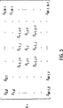
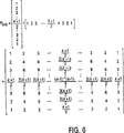
前述のピラミッド・フィルタの考察は、1次元フィルタリングのコンテキストで生じるものであるが、少なくとも一部はこうしたフィルタの対称性により、特別な計算ステップを使用する行方向および列方向の1次元様式で計算する代わりに、ピラミッド2次元フィルタリングを実施することが可能である。1次元のkタップのピラミッド・フィルタを、Fk=[1 2 3 ... ((k−1)/2) ... 3 2 1]で表す場合、対応する2次元ピラミッド・フィルタFk×kは、図6に示されるように導出することができる。図7には、k=11の場合の2次元ピラミッド・フィルタ・カーネルを示した。図5に示された形を有する2次元入力信号、たとえば信号サンプルを想定すると、図4は、ここでは結果的に2次元フィルタリング済み信号サンプル出力Pk×kが得られる行列を示す表であり、2次元入力信号サンプル行列が2次元ピラミッド・フィルタ・カーネルFk×kを使用してフィルタリングされる。 Although the above-mentioned pyramid filter considerations arise in the context of one-dimensional filtering, at least in part, due to the symmetry of such filters, calculations are performed in a one-dimensional manner in the row and column directions using special calculation steps. Instead, pyramid two-dimensional filtering can be implemented. A one-dimensional k-tap pyramid filter is defined as F k = [1 2 3. . . ((K-1) / 2). . . 3 2 1], the corresponding two-dimensional pyramid filter F k × k can be derived as shown in FIG. FIG. 7 shows a two-dimensional pyramid filter kernel when k = 11. Assuming a two-dimensional input signal having the form shown in FIG. 5, for example, signal samples, FIG. 4 is a table showing here a matrix that results in a two-dimensional filtered signal sample output P k × k . A two-dimensional input signal sample matrix is filtered using a two-dimensional pyramid filter kernel F k × k .
図8に示された行列は、2次元入力信号サンプル行列のあらゆる行で1次元kタップ・ピラミッド・フィルタを適用することによって得られ、図9に示された行列は、2次元入力信号サンプル行列のあらゆる列で1次元kタップ・ピラミッド・フィルタを適用することによって得られる。図4の行列は、2次元入力信号サンプル行列に2次元(k×k)タップ・フィルタを適用することによって得られるか、あるいは1次元kタップ・ピラミッド・フィルタを行方向に適用した後、列方向に適用することによって得られる。この方法をフィルタリング済み信号サンプル出力P1×3、P3×1、およびP3×3に適用すると、以下の関係が生じる。 The matrix shown in FIG. 8 is obtained by applying a one-dimensional k-tap pyramid filter on every row of the two-dimensional input signal sample matrix, and the matrix shown in FIG. 9 is a two-dimensional input signal sample matrix. Can be obtained by applying a one-dimensional k-tap pyramid filter on every column. The matrix of FIG. 4 can be obtained by applying a two-dimensional (k × k) tap filter to the two-dimensional input signal sample matrix, or after applying a one-dimensional k-tap pyramid filter in the row direction, Obtained by applying in direction. Applying this method to filtered signal sample outputs P 1 × 3 , P 3 × 1 , and P 3 × 3 yields the following relationship:
フィルタリング済み信号サンプル出力P5×1、P1×5、およびP5×5を生成すると、以下の関係が生じる。 Generating the filtered signal sample outputs P 5 × 1 , P 1 × 5 , and P 5 × 5 yields the following relationship:
同様に、フィルタリング済み信号サンプル出力P7×1、P1×7、およびP7×7を生成すると、以下の関係が生じる。 Similarly, generating filtered signal sample outputs P 7 × 1 , P 1 × 7 , and P 7 × 7 yields the following relationship:
同様に、フィルタリング済み信号サンプル出力P9×1、P1×9、およびP9×9を生成すると、以下の関係が生じる。 Similarly, generating filtered signal sample outputs P 9 × 1 , P 1 × 9 , and P 9 × 9 yields the following relationship:
さらに、フィルタリング済み信号サンプル出力P11×1、P1×11、およびP11×11を生成すると、以下の関係が生じる。 Furthermore, generating filtered signal sample outputs P 11 × 1 , P 1 × 11 , and P 11 × 11 gives the following relationship:
数学的に処理すると、以下が得られる。 Processing mathematically gives:
上記の数式[1]は、次数2N−1の直接2次元ピラミッド・フィルタ・アーキテクチャが(この例ではNは6)、次数[2(N−1)−1]、すなわち9の4つの2次元ピラミッド・フィルタを使用するか、または、4つの信号サンプル行列P9×9 i−1,j−1、P9×9 i−1,j+1、P9×9 i+1,j−1、P9×9 i+1,j+1、および次数2N−1(この例ではNは11)のフィルタが行方向と列方向の14個の1次元ピラミッド・フィルタを使用する次数[2(N−1)−1]の1つの2次元ピラミッド・フィルタのいずれかを使用して潜在的に実施可能であることを示している。また、次数[2(N−2)−1](すなわち7)の1つの2次元ピラミッド・フィルタを使用してP7×7 i,jを生成し、次数[2(N−2)−1](すなわちここでは7)のこの例では2つの1次元ピラミッド・フィルタを使用して2つの信号サンプル行列P7×1 i,j、P1×7 i,jを生成する。図3は、こうした実施形態を示す概略図であるが、もちろん請求された主題の範囲はこの特定の実施または実施形態に限定されるものではない。たとえば次数2(N−1)−1、ここではNが6であるため次数9の、4つの2次元ピラミッド・フィルタによって生成された出力信号サンプルに対応する出力信号サンプルおよび次数2(N−2)−1、ここでは次数7の2次元ピラミッド・フィルタによって生成された出力信号サンプルは、必ずしも2次元ピラミッド・フィルタで生成しなくてもよい。一例として、これらの出力信号は1次元ピラミッド・フィルタを使用して生成してもよい。こうしたフィルタの1つが図2に示されているが、ここでも、図3に示されたアーキテクチャ用の出力信号を生成するために、追加の方法を使用することができる。
The above equation [1] is a direct 2D pyramid filter architecture of order 2N-1 (N is 6 in this example) and order [2 (N-1) -1], ie, 4 2D of 9 Use a pyramid filter, or four signal sample matrices P 9 × 9 i−1, j−1 , P 9 × 9 i−1, j + 1 , P 9 × 9 i + 1, j−1 , P 9 × 9 i + 1, j + 1 , and an order of 2N-1 (N is 11 in this example) use 14 one-dimensional pyramid filters in the row and column directions of order [2 (N-1) -1] It shows that it can potentially be implemented using any one of the two-dimensional pyramid filters. Also, P 7 × 7 i, j is generated using one two-dimensional pyramid filter of order [2 (N−2) −1] (ie, 7), and order [2 (N−2) −1. ] (I.e., 7 here), two signal sample matrices P 7 × 1 i, j , P 1 × 7 i, j are generated using two one-dimensional pyramid filters. FIG. 3 is a schematic diagram illustrating such an embodiment, but of course the scope of the claimed subject matter is not limited to this particular embodiment or embodiment. For example, an output signal sample corresponding to an output signal sample generated by four two-dimensional pyramid filters of
図3は、集積回路(IC)300を示した図であるが、もちろん必ずしも単一の集積回路チップ上で代替の実施形態を実施しなくてもよい。IC 300は、次数2N−1の2次元ピラミッド・フィルタ・アーキテクチャを含み、ここでNは5よりも大きい正の整数、この例では6であり、動作中、それぞれのクロック・サイクルで少なくとも以下のものを生成することができる。図3では、ピラミッド・フィルタリング済み出力信号は、次数2N−1、ここでもNは6であるためこの例では次数11の、14個の1次元ピラミッド・フィルタ、330、332、334、340、342、344、350、352、354、360、362、364、366、および368によって生成された出力信号に対応して生成される。ピラミッド・フィルタリング済み出力信号は、4つの2次元ピラミッド・フィルタ、あるいは、信号サンプル行列P9×9 i−1,j−1、P9×9 i−1,j+1、P9×9 i+1,j−1、P9×9 i+1,j+1を使用する次数[2(N−1)−1]すなわちNは6であるためここでは次数9の1つの2次元ピラミッドの、いずれかによって生成された出力信号に対応して生成される。これらの出力信号は、図3の加算器310で合計される。ピラミッド・フィルタリング済み出力信号はまた、信号サンプル行列P7×7 i,jを使用する次数[2(N−2)−1]すなわちNは6であるためここでは次数7の1つの2次元ピラミッド・フィルタおよび信号サンプル行列P7×1 i,j、P1×7 i,jを使用する次数2(N−2)−1の2つの1次元ピラミッド・フィルタによって生成された出力信号に対応して生成される。これらの3つの出力信号P7×7 i,j、P7×1 i,j、P1×7 i,j、および入力信号si,jは、図3の加算器390で合計される。同様に、図3の実装におけるこの2次元ピラミッド・フィルタ・アーキテクチャ実装でのそれぞれの出力信号、たとえば出力信号330、332、334、340、342、344、350、352、354、360、362、364、366、および368は、図3の加算器370および375によって、2次元ピラミッド・フィルタ・アーキテクチャのそれぞれのクロック・サイクルで合計される。加算器380によって出力信号310、370、375、および390は合計される。もちろん、図3は実施の可能な一例にすぎず、請求された主題の範囲はこの実施または他の特定の実施に限定されるものではない。
FIG. 3 illustrates an integrated circuit (IC) 300, but of course, alternative embodiments may not necessarily be implemented on a single integrated circuit chip.
たとえば、Nは6に限定されるものではない。同様に、2次元ピラミッド・フィルタによって生成された出力信号に対応するピラミッド・フィルタリング済み出力信号は、1次元ピラミッド・フィルタまたは2次元ピラミッド・フィルタによって実施されるものとは限定されない。同様に、前述のように、1次元フィルタが使用される場合、フィルタは前述の2001年1月3日出願のTinku Acharyaによる「Multiplierless Pyramid Filter」という名称の米国特許出願第09/754684号または前述の2001年3月28日出願のTinku Acharyaによる「Pyramid Filter」という名称の米国特許出願第09/820108号(代理人整理番号042390.P11211)に記載された実施方法に限定されるものではない。たとえば、乗算器なしピラミッド・フィルタ以外の1次元ピラミッド・フィルタを使用することができる。同様に、実施に応じて、様々な数のこうしたピラミッド・フィルタおよび様々な次数のこうしたピラミッド・フィルタを使用することができる。たとえば、出力信号は、様々な数、寸法、または次数のピラミッド・フィルタに対応するピラミッド・フィルタリング済み出力信号を生成するように、組み合わせるかまたは処理することができる。 For example, N is not limited to 6. Similarly, the pyramid filtered output signal corresponding to the output signal generated by the two-dimensional pyramid filter is not limited to being implemented by a one-dimensional pyramid filter or a two-dimensional pyramid filter. Similarly, as described above, if a one-dimensional filter is used, the filter may be the aforementioned US patent application Ser. No. 09/754684, named “Multipleless Pyramid Filter” by Tinku Acharya, filed Jan. 3, 2001, or the aforementioned. Is not limited to the implementation described in US patent application Ser. No. 09/820108 (Attorney Docket No. 0423390.P11211) entitled “Pyramid Filter” by Tinku Acharya, filed Mar. 28, 2001. For example, a one-dimensional pyramid filter other than a multiplierless pyramid filter can be used. Similarly, various numbers of such pyramid filters and various orders of such pyramid filters may be used, depending on the implementation. For example, the output signals can be combined or processed to produce pyramid filtered output signals corresponding to various numbers, dimensions, or orders of pyramid filters.
もちろん、これまで特定の実施形態について説明してきたが、請求した主題の範囲は特定の実施形態または実施に限定されるものではないことを理解されよう。たとえば、一実施形態はハードウェアで可能であり、他の実施形態はソフトウェアで可能である。同様に、一実施形態は、ファームウェア、あるいはたとえばハードウェア、ソフトウェア、またはファームウェアの任意の組合せで可能である。同様に、請求した主題の範囲はこの点で限定されるものではないが、一実施形態は記憶媒体などの製品を含むことができる。たとえばCD−ROMまたはディスクなどのこうした記憶媒体は、その上に命令を格納することが可能であり、この命令がコンピュータ・システムまたはプラットフォーム、あるいはイメージング・システムなどのシステムによって実行されると、結果として、たとえば前述のようにイメージまたはビデオをフィルタリングまたは処理する方法の一実施形態などの請求した主題に従った方法の一実施形態が実行されることになる。たとえば、イメージ処理プラットフォームまたはイメージング処理システムは、イメージ処理ユニット、ビデオまたはイメージ入出力デバイス、および/またはメモリを含むことができる。 Of course, while specific embodiments have been described above, it will be understood that the scope of the claimed subject matter is not limited to specific embodiments or implementations. For example, one embodiment can be hardware and the other embodiment can be software. Similarly, an embodiment can be firmware or any combination of hardware, software, or firmware, for example. Similarly, while the scope of the claimed subject matter is not limited in this respect, one embodiment may include products such as storage media. Such a storage medium, such as a CD-ROM or disk, for example, can store instructions thereon, which when executed by a computer system or platform, or a system such as an imaging system, results in An embodiment of a method in accordance with the claimed subject matter will be performed, eg, an embodiment of a method for filtering or processing an image or video as described above. For example, an image processing platform or imaging processing system can include an image processing unit, a video or image input / output device, and / or a memory.
以上、本発明の一定の特徴について本明細書で例示および説明してきたが、これで当分野の技術者であれば、多くの修正、置換、変更、および等価形態を思いつくであろう。したがって、添付の特許請求の範囲は、請求した主題の真の精神を逸脱することなく、こうしたすべての修正および変更をカバーすることを意図したものであることが理解されよう。 While certain features of the invention have been illustrated and described herein, many modifications, substitutions, changes, and equivalents will occur to those skilled in the art. Accordingly, it will be understood that the appended claims are intended to cover all such modifications and changes without departing from the true spirit of the claimed subject matter.
Claims (3)
前記次数2N−1の2次元ピラミッド・フィルタ・アーキテクチャが、動作中にそれぞれのクロック・サイクルで、少なくとも
次数2N−1の14個の1次元ピラミッド・フィルタによって生成された出力信号に対応するピラミッド・フィルタリング済み出力信号と、
次数[2(N−1)−1]の4つの2次元ピラミッド・フィルタ、または、次数[2(N−1)−1]の信号サンプル行列を使用する次数[2(N−1)−1]の1つの2次元ピラミッド・フィルタのいずれかによって生成された、出力信号に対応するピラミッド・フィルタリング済み出力信号とを生成可能であり、
前記2次元ピラミッド・フィルタ・アーキテクチャ内のそれぞれの出力信号が、前記2次元ピラミッド・フィルタ・アーキテクチャのそれぞれのクロック・サイクルで合計される集積回路。Including a two-dimensional pyramid filter architecture of order 2N-1, where N is a positive integer greater than 5,
The two-dimensional pyramid filter architecture of order 2N-1 is a pyramid corresponding to the output signal generated by at least fourteen 1-dimensional pyramid filters of order 2N-1 in each clock cycle during operation. The filtered output signal, and
Order [2 (N-1) -1] using four two-dimensional pyramid filters of order [2 (N-1) -1] or a signal sample matrix of order [2 (N-1) -1] And a pyramid filtered output signal corresponding to the output signal generated by any one of the two-dimensional pyramid filters of
An integrated circuit in which each output signal in the two-dimensional pyramid filter architecture is summed in each clock cycle of the two-dimensional pyramid filter architecture.
前記2次元ピラミッド・フィルタ・アーキテクチャのそれぞれのクロック・サイクルで次数2N−1の14個の1次元ピラミッド・フィルタによって生成された出力信号に対応するピラミッド・フィルタリング済み出力信号と、
次数[2(N−1)−1]の4つの2次元ピラミッド・フィルタ、または、次数[2(N−1)−1]の信号サンプル行列を使用する次数[2(N−1)−1]の1つの2次元ピラミッド・フィルタのいずれかによって生成された、出力信号に対応するピラミッド・フィルタリング済み出力信号とを、合計することを含む方法。A method of filtering an image using a two-dimensional pyramid filter architecture of order 2N-1, where N is a positive integer greater than 5, said method comprising:
A pyramid filtered output signal corresponding to the output signal generated by the 14 1D pyramid filters of order 2N-1 in each clock cycle of the 2D pyramid filter architecture;
Order [2 (N-1) -1] using four two-dimensional pyramid filters of order [2 (N-1) -1] or a signal sample matrix of order [2 (N-1) -1] And summing together the pyramid filtered output signal corresponding to the output signal generated by one of the two-dimensional pyramid filters.
前記イメージ処理ユニットが、少なくとも1つの2次元ピラミッド・フィルタ・アーキテクチャを含み、
前記少なくとも1つの2次元ピラミッド・フィルタ・アーキテクチャが、
次数2N−1の2次元ピラミッド・フィルタ・アーキテクチャを含み、Nは5より大きい正の整数であって、
前記次数2N−1の2次元ピラミッド・フィルタ・アーキテクチャが、動作中にそれぞれのクロック・サイクルで、少なくとも
次数2N−1の14個の1次元ピラミッド・フィルタによって生成された出力信号に対応するピラミッド・フィルタリング済み出力信号と、
次数[2(N−1)−1]の4つの2次元ピラミッド・フィルタ、または、次数[2(N−1)−1]の信号サンプル行列を使用する次数[2(N−1)−1]の1つの2次元ピラミッド・フィルタのいずれかによって生成された、出力信号に対応するピラミッド・フィルタリング済み出力信号とを生成可能であり、
前記2次元ピラミッド・フィルタ・アーキテクチャ内のそれぞれの出力信号が、前記2次元ピラミッド・フィルタ・アーキテクチャのそれぞれのクロック・サイクルで合計されるシステム。An image processing system including an image processing unit for filtering a scanned color image,
The image processing unit comprises at least one two-dimensional pyramid filter architecture;
The at least one two-dimensional pyramid filter architecture comprises:
Including a two-dimensional pyramid filter architecture of order 2N-1, where N is a positive integer greater than 5,
The two-dimensional pyramid filter architecture of order 2N-1 is a pyramid corresponding to the output signal generated by at least fourteen 1-dimensional pyramid filters of order 2N-1 in each clock cycle during operation. The filtered output signal, and
Order [2 (N-1) -1] using four two-dimensional pyramid filters of order [2 (N-1) -1] or a signal sample matrix of order [2 (N-1) -1] And a pyramid filtered output signal corresponding to the output signal generated by any one of the two-dimensional pyramid filters of
A system in which each output signal in the two-dimensional pyramid filter architecture is summed in each clock cycle of the two-dimensional pyramid filter architecture.
Applications Claiming Priority (2)
| Application Number | Priority Date | Filing Date | Title |
|---|---|---|---|
| US09/846,609 US6725247B2 (en) | 2001-04-30 | 2001-04-30 | Two-dimensional pyramid filter architecture |
| PCT/US2002/011753 WO2002089061A2 (en) | 2001-04-30 | 2002-04-12 | Two-dimensional pyramid filter architecture |
Publications (3)
| Publication Number | Publication Date |
|---|---|
| JP2005505027A JP2005505027A (en) | 2005-02-17 |
| JP2005505027A5 JP2005505027A5 (en) | 2005-12-22 |
| JP4102198B2 true JP4102198B2 (en) | 2008-06-18 |
Family
ID=25298410
Family Applications (1)
| Application Number | Title | Priority Date | Filing Date |
|---|---|---|---|
| JP2002586286A Expired - Lifetime JP4102198B2 (en) | 2001-04-30 | 2002-04-12 | 2D pyramid filter architecture |
Country Status (10)
| Country | Link |
|---|---|
| US (2) | US6725247B2 (en) |
| EP (1) | EP1396081B1 (en) |
| JP (1) | JP4102198B2 (en) |
| KR (1) | KR100550676B1 (en) |
| CN (1) | CN1505866A (en) |
| AT (1) | ATE298471T1 (en) |
| AU (1) | AU2002256213A1 (en) |
| DE (1) | DE60204778T2 (en) |
| TW (1) | TW556120B (en) |
| WO (1) | WO2002089061A2 (en) |
Families Citing this family (9)
| Publication number | Priority date | Publication date | Assignee | Title |
|---|---|---|---|---|
| US6636167B1 (en) * | 2000-10-31 | 2003-10-21 | Intel Corporation | Method of generating Huffman code length information |
| US6563439B1 (en) * | 2000-10-31 | 2003-05-13 | Intel Corporation | Method of performing Huffman decoding |
| US6725247B2 (en) * | 2001-04-30 | 2004-04-20 | Intel Corporation | Two-dimensional pyramid filter architecture |
| US7433084B2 (en) * | 2002-07-01 | 2008-10-07 | Xerox Corporation | Digital de-screening technique for scanned documents |
| US7366746B2 (en) * | 2004-02-12 | 2008-04-29 | Xerox Corporation | Finite impulse response filter method and apparatus |
| US7904841B1 (en) | 2007-10-12 | 2011-03-08 | Lockheed Martin Corporation | Method and system for optimizing digital filters |
| JP5620829B2 (en) * | 2011-01-11 | 2014-11-05 | キヤノン株式会社 | Data processing apparatus, image processing apparatus, and methods thereof |
| US8737759B2 (en) * | 2011-07-01 | 2014-05-27 | Intel Corporation | Image blurring by partitioning a non-separable fir filter |
| US9626749B2 (en) | 2014-12-10 | 2017-04-18 | Intel Corporation | Sub-pixel modification of digital images by locally shifting to an arbitrarily dense supergrid |
Family Cites Families (4)
| Publication number | Priority date | Publication date | Assignee | Title |
|---|---|---|---|---|
| US5359674A (en) | 1991-12-11 | 1994-10-25 | David Sarnoff Research Center, Inc. | Pyramid processor integrated circuit |
| US5963675A (en) * | 1996-04-17 | 1999-10-05 | Sarnoff Corporation | Pipelined pyramid processor for image processing systems |
| US6018597A (en) * | 1997-03-21 | 2000-01-25 | Intermec Ip Corporation | Method and apparatus for changing or mapping video or digital images from one image density to another |
| US6725247B2 (en) * | 2001-04-30 | 2004-04-20 | Intel Corporation | Two-dimensional pyramid filter architecture |
-
2001
- 2001-04-30 US US09/846,609 patent/US6725247B2/en not_active Expired - Fee Related
-
2002
- 2002-03-12 TW TW091104602A patent/TW556120B/en not_active IP Right Cessation
- 2002-04-12 DE DE60204778T patent/DE60204778T2/en not_active Expired - Lifetime
- 2002-04-12 AT AT02725662T patent/ATE298471T1/en not_active IP Right Cessation
- 2002-04-12 EP EP02725662A patent/EP1396081B1/en not_active Expired - Lifetime
- 2002-04-12 KR KR1020037014161A patent/KR100550676B1/en active IP Right Grant
- 2002-04-12 WO PCT/US2002/011753 patent/WO2002089061A2/en active IP Right Grant
- 2002-04-12 AU AU2002256213A patent/AU2002256213A1/en not_active Abandoned
- 2002-04-12 JP JP2002586286A patent/JP4102198B2/en not_active Expired - Lifetime
- 2002-04-12 CN CNA028091191A patent/CN1505866A/en active Pending
-
2004
- 2004-02-04 US US10/772,630 patent/US20040158594A1/en not_active Abandoned
Also Published As
| Publication number | Publication date |
|---|---|
| CN1505866A (en) | 2004-06-16 |
| DE60204778T2 (en) | 2006-05-18 |
| KR20040015207A (en) | 2004-02-18 |
| WO2002089061A2 (en) | 2002-11-07 |
| JP2005505027A (en) | 2005-02-17 |
| US6725247B2 (en) | 2004-04-20 |
| EP1396081A2 (en) | 2004-03-10 |
| AU2002256213A1 (en) | 2002-11-11 |
| KR100550676B1 (en) | 2006-02-08 |
| US20040158594A1 (en) | 2004-08-12 |
| US20020194234A1 (en) | 2002-12-19 |
| EP1396081B1 (en) | 2005-06-22 |
| TW556120B (en) | 2003-10-01 |
| ATE298471T1 (en) | 2005-07-15 |
| WO2002089061A3 (en) | 2003-10-30 |
| DE60204778D1 (en) | 2005-07-28 |
Similar Documents
| Publication | Publication Date | Title |
|---|---|---|
| KR100437997B1 (en) | A symmetric filtering based vlsi architecture for image compression | |
| JP4102198B2 (en) | 2D pyramid filter architecture | |
| JP4323808B2 (en) | Two-dimensional pyramid filter architecture | |
| EP1415277B1 (en) | Pyramid filter | |
| US6662200B2 (en) | Multiplierless pyramid filter | |
| US20020184276A1 (en) | Two-dimensional pyramid filter architecture | |
| EP1380107B1 (en) | Two-dimensional pyramid filter architecture | |
| Jenkin | Digital image processing in the frequency domain | |
| JPS62293483A (en) | Picture processor |
Legal Events
| Date | Code | Title | Description |
|---|---|---|---|
| A521 | Request for written amendment filed |
Free format text: JAPANESE INTERMEDIATE CODE: A523 Effective date: 20050408 |
|
| A621 | Written request for application examination |
Free format text: JAPANESE INTERMEDIATE CODE: A621 Effective date: 20050408 |
|
| A131 | Notification of reasons for refusal |
Free format text: JAPANESE INTERMEDIATE CODE: A131 Effective date: 20070925 |
|
| A521 | Request for written amendment filed |
Free format text: JAPANESE INTERMEDIATE CODE: A523 Effective date: 20071225 |
|
| TRDD | Decision of grant or rejection written | ||
| A01 | Written decision to grant a patent or to grant a registration (utility model) |
Free format text: JAPANESE INTERMEDIATE CODE: A01 Effective date: 20080219 |
|
| A61 | First payment of annual fees (during grant procedure) |
Free format text: JAPANESE INTERMEDIATE CODE: A61 Effective date: 20080321 |
|
| FPAY | Renewal fee payment (event date is renewal date of database) |
Free format text: PAYMENT UNTIL: 20110328 Year of fee payment: 3 |
|
| R150 | Certificate of patent or registration of utility model |
Free format text: JAPANESE INTERMEDIATE CODE: R150 Ref document number: 4102198 Country of ref document: JP Free format text: JAPANESE INTERMEDIATE CODE: R150 |
|
| R250 | Receipt of annual fees |
Free format text: JAPANESE INTERMEDIATE CODE: R250 |
|
| FPAY | Renewal fee payment (event date is renewal date of database) |
Free format text: PAYMENT UNTIL: 20120328 Year of fee payment: 4 |
|
| R250 | Receipt of annual fees |
Free format text: JAPANESE INTERMEDIATE CODE: R250 |
|
| FPAY | Renewal fee payment (event date is renewal date of database) |
Free format text: PAYMENT UNTIL: 20130328 Year of fee payment: 5 |
|
| FPAY | Renewal fee payment (event date is renewal date of database) |
Free format text: PAYMENT UNTIL: 20130328 Year of fee payment: 5 |
|
| FPAY | Renewal fee payment (event date is renewal date of database) |
Free format text: PAYMENT UNTIL: 20130328 Year of fee payment: 5 |
|
| FPAY | Renewal fee payment (event date is renewal date of database) |
Free format text: PAYMENT UNTIL: 20130328 Year of fee payment: 5 |
|
| FPAY | Renewal fee payment (event date is renewal date of database) |
Free format text: PAYMENT UNTIL: 20130328 Year of fee payment: 5 |
|
| FPAY | Renewal fee payment (event date is renewal date of database) |
Free format text: PAYMENT UNTIL: 20140328 Year of fee payment: 6 |
|
| R250 | Receipt of annual fees |
Free format text: JAPANESE INTERMEDIATE CODE: R250 |
|
| R250 | Receipt of annual fees |
Free format text: JAPANESE INTERMEDIATE CODE: R250 |
|
| R250 | Receipt of annual fees |
Free format text: JAPANESE INTERMEDIATE CODE: R250 |
|
| R250 | Receipt of annual fees |
Free format text: JAPANESE INTERMEDIATE CODE: R250 |
|
| R250 | Receipt of annual fees |
Free format text: JAPANESE INTERMEDIATE CODE: R250 |
|
| R250 | Receipt of annual fees |
Free format text: JAPANESE INTERMEDIATE CODE: R250 |
|
| R250 | Receipt of annual fees |
Free format text: JAPANESE INTERMEDIATE CODE: R250 |
|
| R250 | Receipt of annual fees |
Free format text: JAPANESE INTERMEDIATE CODE: R250 |
|
| R250 | Receipt of annual fees |
Free format text: JAPANESE INTERMEDIATE CODE: R250 |
|
| R250 | Receipt of annual fees |
Free format text: JAPANESE INTERMEDIATE CODE: R250 |
|
| EXPY | Cancellation because of completion of term |