JP4101983B2 - Image processing device - Google Patents
Image processing device Download PDFInfo
- Publication number
- JP4101983B2 JP4101983B2 JP23273599A JP23273599A JP4101983B2 JP 4101983 B2 JP4101983 B2 JP 4101983B2 JP 23273599 A JP23273599 A JP 23273599A JP 23273599 A JP23273599 A JP 23273599A JP 4101983 B2 JP4101983 B2 JP 4101983B2
- Authority
- JP
- Japan
- Prior art keywords
- image
- enlargement
- unit
- signal
- image processing
- Prior art date
- Legal status (The legal status is an assumption and is not a legal conclusion. Google has not performed a legal analysis and makes no representation as to the accuracy of the status listed.)
- Expired - Fee Related
Links
- 238000012545 processing Methods 0.000 title claims description 179
- 230000009467 reduction Effects 0.000 claims description 105
- 238000004364 calculation method Methods 0.000 claims description 37
- 238000006243 chemical reaction Methods 0.000 claims description 36
- 238000000034 method Methods 0.000 claims description 25
- 238000011946 reduction process Methods 0.000 claims description 20
- 230000008569 process Effects 0.000 claims description 19
- 239000003086 colorant Substances 0.000 claims description 11
- 230000011218 segmentation Effects 0.000 claims description 10
- 238000010586 diagram Methods 0.000 description 12
- 238000003672 processing method Methods 0.000 description 5
- 238000012546 transfer Methods 0.000 description 5
- 238000012937 correction Methods 0.000 description 4
- 230000003287 optical effect Effects 0.000 description 4
- 230000002093 peripheral effect Effects 0.000 description 4
- 230000032258 transport Effects 0.000 description 4
- 238000003702 image correction Methods 0.000 description 3
- 238000003384 imaging method Methods 0.000 description 3
- 239000004065 semiconductor Substances 0.000 description 3
- 238000003705 background correction Methods 0.000 description 2
- 230000007175 bidirectional communication Effects 0.000 description 2
- 238000004140 cleaning Methods 0.000 description 2
- 230000000694 effects Effects 0.000 description 2
- 239000000463 material Substances 0.000 description 2
- 230000007246 mechanism Effects 0.000 description 2
- 238000007639 printing Methods 0.000 description 2
- 238000003756 stirring Methods 0.000 description 2
- 230000007723 transport mechanism Effects 0.000 description 2
- 230000015572 biosynthetic process Effects 0.000 description 1
- 239000000969 carrier Substances 0.000 description 1
- 230000006854 communication Effects 0.000 description 1
- 238000004891 communication Methods 0.000 description 1
- 238000013500 data storage Methods 0.000 description 1
- 230000010339 dilation Effects 0.000 description 1
- 230000006870 function Effects 0.000 description 1
- 239000011521 glass Substances 0.000 description 1
- 238000010438 heat treatment Methods 0.000 description 1
- 239000004973 liquid crystal related substance Substances 0.000 description 1
- 230000000873 masking effect Effects 0.000 description 1
- 238000002156 mixing Methods 0.000 description 1
- 238000003825 pressing Methods 0.000 description 1
- 238000004886 process control Methods 0.000 description 1
- 230000004044 response Effects 0.000 description 1
- 238000000926 separation method Methods 0.000 description 1
- 230000003068 static effect Effects 0.000 description 1
- 238000003860 storage Methods 0.000 description 1
- 239000002699 waste material Substances 0.000 description 1
- 238000004804 winding Methods 0.000 description 1
Images


Classifications
-
- H—ELECTRICITY
- H04—ELECTRIC COMMUNICATION TECHNIQUE
- H04N—PICTORIAL COMMUNICATION, e.g. TELEVISION
- H04N1/00—Scanning, transmission or reproduction of documents or the like, e.g. facsimile transmission; Details thereof
- H04N1/387—Composing, repositioning or otherwise geometrically modifying originals
- H04N1/393—Enlarging or reducing
-
- H—ELECTRICITY
- H04—ELECTRIC COMMUNICATION TECHNIQUE
- H04N—PICTORIAL COMMUNICATION, e.g. TELEVISION
- H04N1/00—Scanning, transmission or reproduction of documents or the like, e.g. facsimile transmission; Details thereof
- H04N1/40—Picture signal circuits
- H04N1/40062—Discrimination between different image types, e.g. two-tone, continuous tone
-
- H—ELECTRICITY
- H04—ELECTRIC COMMUNICATION TECHNIQUE
- H04N—PICTORIAL COMMUNICATION, e.g. TELEVISION
- H04N1/00—Scanning, transmission or reproduction of documents or the like, e.g. facsimile transmission; Details thereof
- H04N1/46—Colour picture communication systems
- H04N1/56—Processing of colour picture signals
- H04N1/60—Colour correction or control
- H04N1/6072—Colour correction or control adapting to different types of images, e.g. characters, graphs, black and white image portions
Landscapes
- Engineering & Computer Science (AREA)
- Multimedia (AREA)
- Signal Processing (AREA)
- Image Processing (AREA)
- Facsimile Image Signal Circuits (AREA)
- Editing Of Facsimile Originals (AREA)
- Color Image Communication Systems (AREA)
Description
【0001】
【発明の属する技術分野】
本発明は、たとえば、原稿上のカラー画像を読取って入力し、その複製画像を形成するデジタル式複写機などの画像形成装置において、入力された画像信号に対して色変換処理や拡大または縮小処理などを行なう画像処理装置に関する。
【0002】
【従来の技術】
一般に、デジタル式複写機やレーザープリンタでは、より鮮明で好感の持たれる出力画像を実現するため、入力原稿や入力画像信号を画素や領域ごとに文字とそれ以外の種別などとに識別し、その識別信号によって内部での画像処理方法の切換を行なっている。
【0003】
そして、ユーザの要求などで入力画像を拡大または縮小して出力画像を生成する場合、入力される原画像に対し拡大または縮小処理を行なうことは当然だが、画像処理の構成によっては、上記識別信号の拡大または縮小処理も行なわれる。従来、これらの演算を入力画像の特性を考慮することなく、固定の識別信号の拡大縮小処理が行なわれてきた。
【0004】
【発明が解決しようとする課題】
しかし、入力画像が写真などの階調重視の画像であるか、文字画像であるか、また、カラー画像であるかモノクロ画像であるかなどによって、適した画像処理がそれぞれ異なる場合がある。これらを考慮せず、単に識別信号に対し拡大縮小処理を行なうと、その結果、得られる識別信号が原稿の特性に合わない画像処理を選択する場合が起こる。
【0005】
そこで、本発明は、原画像とのずれが少ない拡大縮小処理が行なえ、出力画像の高画質化が図れる画像処理装置を提供することを目的とする。
【0006】
また、本発明は、入力がカラー画像の場合、各色にそれぞれ画像の特性や色の特性を考慮することで更に出力画像の高画質化が図れる画像処理装置を提供することを目的とする。
【0007】
【課題を解決するための手段】
本発明の画像処理装置は、原画像の画像情報から複数の色の色信号を発生する画像入力手段と、この画像入力手段により入力された各色画像信号を新たな色空間に変換し、濃度画像信号を生成する色変換手段と、この色変換手段からの濃度画像信号、および、前記画像入力手段からの各色画像信号のいずれか一方もしくは両方の信号に基づき画素ごとの属性を判断してその識別信号を2値で生成する識別手段と、前記色変換手段からの濃度画像信号に対し所定の第1の画像処理を施すそれぞれが異なる特性を持った複数の画像処理部を有し、これら複数の画像処理部の各出力を前記識別手段からの識別信号により選択して出力する第1の画像処理手段と、この第1の画像処理手段からの画像信号に対し拡大または縮小倍率に基づく拡大または縮小処理を施す画像拡大縮小手段と、前記識別手段からの識別信号に対し前記画像拡大縮小手段の拡大または縮小処理に合わせた拡大または縮小処理を施す識別信号拡大縮小手段と、前記画像拡大縮小手段からの拡大または縮小処理された画像信号に対し所定の第2の画像処理を施すそれぞれが異なる特性を持った複数の画像処理部を有し、これら複数の画像処理部の各出力を前記識別信号拡大縮小手段からの拡大または縮小処理された識別信号により選択して出力する第2の画像処理手段とを具備し、前記識別信号拡大縮小手段は、前記識別手段からの識別信号に対し、前記画像拡大縮小手段の拡大または縮小倍率に対応した拡大または縮小倍率に基づいて対象範囲となる画素情報を切り分けて保持する画素切り分け手段と、この画素切り分け手段により切り分けられた対象範囲の画素情報の論理和、または、論理積、または、最初あるいは最後などの定位置の画素値あるいは倍率に応じた重み付け加算和の演算を行なうことにより拡大または縮小された画素の識別信号を生成する複数の演算手段と、この複数の演算手段の各出力を外部から与えられる切換条件によって選択する選択手段とを具備している。
【0008】
また、本発明の画像処理装置は、原画像の画像情報から複数の色の色信号を発生する画像入力手段と、この画像入力手段により入力された各色画像信号を新たな色空間に変換し、濃度画像信号を生成する色変換手段と、この色変換手段からの濃度画像信号、および、前記画像入力手段からの各色画像信号のいずれか一方もしくは両方の信号に基づき画素ごとの属性を判断してその識別信号を多値で生成する識別手段と、前記色変換手段からの濃度画像信号に対し所定の第1の画像処理を施すそれぞれが異なる特性を持った複数の画像処理部を有し、これら複数の画像処理部の各出力を前記識別手段からの識別信号により選択して出力する第1の画像処理手段と、この第1の画像処理手段からの画像信号に対し拡大または縮小倍率に基づく拡大または縮小処理を施す画像拡大縮小手段と、前記識別手段からの識別信号に対し前記画像拡大縮小手段の拡大または縮小処理に合わせた拡大または縮小処理を施す識別信号拡大縮小手段と、前記画像拡大縮小手段からの拡大または縮小処理された画像信号に対し所定の第2の画像処理を施すそれぞれが異なる特性を持った複数の画像処理部を有し、これら複数の画像処理部の各出力を前記識別信号拡大縮小手段からの拡大または縮小処理された識別信号により選択して出力する第2の画像処理手段とを具備し、前記識別信号拡大縮小手段は、前記識別手段からの識別信号に対し、前記画像拡大縮小手段の拡大または縮小倍率に対応した拡大または縮小倍率に基づいて対象範囲となる画素情報を切り分けて保持する画素切り分け手段と、この画素切り分け手段により切り分けられた対象範囲の画素情報の最初あるいは最後などの定位置の画素値、または、対象画素中の最大値あるいは最小値、または、倍率に応じた重み付け加算和の演算を行なうことにより拡大または縮小された画素の識別信号を生成する複数の演算手段と、この複数の演算手段の各出力を外部から与えられる切換条件によって選択する選択手段とを具備している。
【0009】
また、本発明の画像処理装置は、原画像の画像情報から複数の色の色信号を発生する画像入力手段と、この画像入力手段により入力された各色画像信号を新たな色空間に変換し、濃度画像信号を生成する色変換手段と、この色変換手段からの濃度画像信号、および、前記画像入力手段からの前もって入力された各色画像信号のいずれか一方もしくは両方の信号に基づき入力画像を1つ以上の領域に分割し、この分割した領域ごとの属性を判断してその領域識別信号を生成する領域識別手段と、前記色変換手段からの濃度画像信号、前記画像入力手段からの各色画像信号のいずれか一方もしくは両方の信号、および、前記領域識別手段からの領域識別信号に基づき画素ごとの属性を判断してその属性識別信号を2値で生成する属性識別手段と、前記色変換手段からの濃度画像信号に対し所定の第1の画像処理を施すそれぞれが異なる特性を持った複数の画像処理部を有し、これら複数の画像処理部の各出力を前記属性識別手段からの属性識別信号により選択して出力する第1の画像処理手段と、この第1の画像処理手段からの画像信号に対し拡大または縮小倍率に基づく拡大または縮小処理を施す画像拡大縮小手段と、前記属性識別手段からの属性識別信号に対し前記画像拡大縮小手段の拡大または縮小処理に合わせた拡大または縮小処理を施す識別信号拡大縮小手段と、前記画像拡大縮小手段からの拡大または縮小処理された画像信号に対し所定の第2の画像処理を施すそれぞれが異なる特性を持った複数の画像処理部を有し、これら複数の画像処理部の各出力を前記識別信号拡大縮小手段からの拡大または縮小処理された識別信号により選択して出力する第2の画像処理手段とを具備し、前記識別信号拡大縮小手段は、前記属性識別手段からの属性識別信号に対し、前記画像拡大縮小手段の拡大または縮小倍率に対応した拡大または縮小倍率に基づいて対象範囲となる画素情報を切り分けて保持する画素切り分け手段と、この画素切り分け手段により切り分けられた対象範囲の画素情報の論理和、または、論理積、または、最初あるいは最後などの定位置の画素値あるいは倍率に応じた重み付け加算和の演算を行なうことにより拡大または縮小された画素の識別信号を生成する複数の演算手段と、この複数の演算手段の各出力を外部から与えられる切換条件、および、前記領域識別手段からの領域識別信号によって選択する選択手段とを具備している。
【0010】
さらに、本発明の画像処理装置は、原画像の画像情報から複数の色の色信号を発生する画像入力手段と、この画像入力手段により入力された各色画像信号を新たな色空間に変換し、濃度画像信号を生成する色変換手段と、この色変換手段からの濃度画像信号、および、前記画像入力手段からの前もって入力された各色画像信号のいずれか一方もしくは両方の信号に基づき入力画像を1つ以上の領域に分割し、この分割した領域ごとの属性を判断してその領域識別信号を生成する領域識別手段と、前記色変換手段からの濃度画像信号、前記画像入力手段からの各色画像信号のいずれか一方もしくは両方の信号、および、前記領域識別手段からの領域識別信号に基づき画素ごとの属性を判断してその属性識別信号を多値で生成する属性識別手段と、前記色変換手段からの濃度画像信号に対し所定の第1の画像処理を施すそれぞれが異なる特性を持った複数の画像処理部を有し、これら複数の画像処理部の各出力を前記属性識別手段からの属性識別信号により選択して出力する第1の画像処理手段と、この第1の画像処理手段からの画像信号に対し拡大または縮小倍率に基づく拡大または縮小処理を施す画像拡大縮小手段と、前記属性識別手段からの属性識別信号に対し前記画像拡大縮小手段の拡大または縮小処理に合わせた拡大または縮小処理を施す識別信号拡大縮小手段と、前記画像拡大縮小手段からの拡大または縮小処理された画像信号に対し所定の第2の画像処理を施すそれぞれが異なる特性を持った複数の画像処理部を有し、これら複数の画像処理部の各出力を前記識別信号拡大縮小手段からの拡大または縮小処理された識別信号により選択して出力する第2の画像処理手段とを具備し、前記識別信号拡大縮小手段は、前記属性識別手段からの属性識別信号に対し、前記画像拡大縮小手段の拡大または縮小倍率に対応した拡大または縮小倍率に基づいて対象範囲となる画素情報を切り分けて保持する画素切り分け手段と、この画素切り分け手段により切り分けられた対象範囲の画素情報の最初あるいは最後などの定位置の画素値、または、対象画素中の最大値あるいは最小値、または、倍率に応じた重み付け加算和の演算を行なうことにより拡大または縮小された画素の識別信号を生成する複数の演算手段と、この複数の演算手段の各出力を外部から与えられる切換条件、および、前記領域識別手段からの領域識別信号によって選択する選択手段とを具備している。
【0011】
本発明によれば、入力画像の特性などによって識別信号の拡大縮小処理方法を切換え、その結果、得られた識別信号に基づき、入力画像に合った画像処理を選択することで、出力画像の高画質化が図れる。
【0012】
また、入力がカラー画像の場合、各色にそれぞれ画像の特性や色の特性を考慮することで、更に出力画像の高画質化が図れる。
【0013】
【発明の実施の形態】
以下、本発明の実施の形態について図面を参照して説明する。
【0014】
まず、第1の実施の形態について説明する。
【0015】
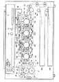
図1は、本発明に係る画像処理装置が適用される、原稿上のカラー画像を読取ってその複製画像を形成するデジタル式カラー複写機などの画像形成装置の内部構成を概略的に示している。この画像形成装置は、大別して、原稿上のカラー画像を読取って入力する画像入力手段としてのカラースキャナ部1と、入力されたカラー画像の複製画像を形成する画像出力手段としてのカラープリンタ部2とから構成されている。
【0016】
カラースキャナ部1は、その上部に原稿台カバー3を有し、閉じた状態にある原稿台カバー3に対向配設され、原稿がセットされる透明ガラスからなる原稿台4を有している。原稿台4の下方には、原稿台4上に載置された原稿を照明する露光ランプ5、露光ランプ5からの光を原稿に集光させるためのリフレクタ6、および、原稿からの反射光を図面に対して左方向に折り曲げる第1ミラー7などが配設されている。露光ランプ5、リフレクタ6、および、第1ミラー7は、第1キャリッジ8に固定されている。第1キャリッジ8は、図示しない歯付きベルトなどを介して図示しないパルスモータによって駆動されることにより、原稿台4の下面に沿って平行移動されるようになっている。
【0017】
第1キャリッジ8に対して図中左側、すなわち、第1ミラー7により反射された光が案内される方向には、図示しない駆動機構(たとえば、歯付きベルト並びに直流モータなど)を介して原稿台4と平行に移動可能に設けられた第2キャリッジ9が配設されている。第2キャリッジ9には、第1ミラー7により案内される原稿からの反射光を図中下方に折り曲げる第2ミラー11、および、第2ミラー11からの反射光を図中右方向に折り曲げる第3ミラー12が互いに直角に配置されている。第2キャリッジ9は、第1キャリッジ8に従動されるとともに、第1キャリッジ8に対して1/2の速度で原稿台4に沿って平行移動されるようになっている。
【0018】
第2,第3ミラー11,12で折り返された光の光軸を含む面内には、第3ミラー12からの反射光を所定の倍率で結像させる結像レンズ13が配置され、結像レンズ13を通過した光の光軸と略直交する面内には、結像レンズ13により集束性が与えられた反射光を電気信号に変換するCCD形カラーイメージセンサ(光電変換素子)15が配設されている。
【0019】
しかして、露光ランプ5からの光をリフレクタ6により原稿台4上の原稿に集光させると、原稿からの反射光は、第1ミラー7、第2ミラー11、第3ミラー12、および、結像レンズ13を介してカラーイメージセンサ15に入射され、ここで入射光がR(レッド),G(グリーン),B(ブルー)の光の3原色に応じた電気信号に変換される。
【0020】
カラープリンタ部2は、周知の減色混合法に基づいて、各色成分ごとに色分解された画像、すなわち、イエロウ(Y)、マゼンタ(M)、シアン(C)、およよび、ブラック(K)の4色の画像をそれぞれ形成する第1〜第4の画像形成部10y,10m,10c,10kを有している。
【0021】
各画像形成部10y,10m,10c,10kの下方には、各画像形成部により形成された各色ごとの画像を図中矢印a方向に搬送する搬送手段としての搬送ベルト21を含む搬送機構20が配設されている。搬送ベルト21は、図示しないモータにより矢印a方向に回転される駆動ローラ91と、駆動ローラ91から所定距離離間された従動ローラ92との間に巻回されて張設され、矢印a方向に一定速度で無端走行される。なお、各画像形成部10y,10m,10c,10kは、搬送ベルト21の搬送方向に沿って直列に配設されている。
【0022】
各画像形成部10y,10m,10c,10kは、それぞれ搬送ベルト21と接する位置で外周面が同一の方向に回転可能に形成された像担持体としての感光体ドラム61y,61m,61c,61kを含んでいる。各感光体ドラム61y,61m,61c,61kは、図示しないモータにより所定の周速度で回転されるようになっている。
【0023】
各感光体ドラム61y,61m,61c,61kは、その軸線が互いに等間隔になるように配設されているとともに、その軸線は搬送ベルト21により画像が搬送される方向と直交するよう配設されている。なお、以下の説明においては、各感光体ドラム61y,61m,61c,61kの軸線方向を主走査方向(第2の方向)とし、感光体ドラム61y,61m,61c,61kの回転方向、すなわち、搬送ベルト21の回転方向(図中矢印a方向)を副走査方向(第1の方向)とする。
【0024】
各感光体ドラム61y,61m,61c,61kの周囲には、主走査方向に延出された帯電手段としての帯電装置62y,62m,62c,62k、除電装置63y,63m,63c,63k、主走査方向に同様に延出された現像手段としての現像ローラ64y,64m,64c,64k、下撹拌ローラ67y,67m,67c,67k、上撹拌ローラ68y,68m,68c,68k、主走査方向に同様に延出された転写手段としての転写装置93y,93m,93c,93k、主走査方向に同様に延出されたクリーニングブレード65y,65m,65c,65k、および、排トナー回収スクリュ66y,66m,66c,66kが、それぞれ感光体ドラム61y,61m,61c,61kの回転方向に沿って順に配置されている。
【0025】
なお、各転写装置93y,93m,93c,93kは、対応する感光体ドラム61y,61m,61c,61kとの間で搬送ベルト21を狭持する位置、すなわち、搬送ベルト21の内側に配設されている。また、後述する露光装置50による露光ポイントは、それぞれ帯電装置62y,62m,62c,62kと現像ローラ64y,64m,64c,64kとの間の感光体ドラム61y,61m,61c,61kの外周面上に形成される。
【0026】
搬送機構20の下方には、各画像形成部10y,10m,10c,10kにより形成された画像を転写する被画像形成媒体(記録媒体)としての用紙Pを複数枚収容した用紙カセット22a,22bが配置されている。
【0027】
用紙カセット22a,22bの一端部であって、従動ローラ92に近接する側には、用紙カセット22a,22bに収容されている用紙Pをその最上部から1枚ずつ取出すピックアップローラ23a,23bが配置されている。ピックアップローラ23a,23bと従動ローラ92との間には、用紙カセット22a,22bから取出された用紙Pの先端と画像形成部10yの感光体ドラム61yに形成されたyトナー像の先端とを整合させるためのレジストローラ24が配置されている。
【0028】
なお、他の感光体ドラム61y,61m,61cに形成されたトナー像は、搬送ベルト21上を搬送される用紙Pの搬送タイミングに合せて各転写位置に供給される。
【0029】
レジストローラ24と第1の画像形成部10yとの間であって、従動ローラ92の近傍、すなわち、実質的に搬送ベルト21を挟んで従動ローラ92の外周上には、レジストローラ24を介して所定のタイミングで搬送される用紙Pに静電吸着力を付与するための吸着ローラ26が配設されている。なお、吸着ローラ26の軸線と従動ローラ92の軸線とは、互いに平行になるように設定されている。
【0030】
搬送ベルト21の一端であって、駆動ローラ91の近傍、すなわち、実質的に搬送ベルト21を挟んで駆動ローラ91の外周上には、搬送ベルト21上に形成された画像の位置を検知するための位置ずれセンサ96が配設されている。位置ずれセンサ96は、たとえば、透過形あるいは反射形の光センサにより構成される。
【0031】
駆動ローラ91の外周上であって、位置ずれセンサ96の下流側の搬送ベルト21上には、搬送ベルト21上に付着したトナーあるいは用紙Pの紙かすなどを除去するための搬送ベルトクリーニング装置95が配置されている。
【0032】
搬送ベルト21を介して搬送された用紙Pが駆動ローラ91から離脱されて、さらに搬送される方向には、用紙Pを所定温度に加熱することにより用紙Pに転写されたトナー像を溶融し、トナー像を用紙Pに定着させる定着装置80が配設されている。定着装置80は、ヒー卜ロ一ラ対81、オイル塗付ローラ82,83、ウェブ巻取りローラ84、ウェブローラ85、ウェブ押付けローラ86とから構成されている。用紙P上に形成されたトナーを用紙に定着させ、排紙ローラ対87により排出される。
【0033】
各感光体ドラム61y,61m,61c,61kの外周面上にそれぞれ色分解された静電潜像を形成する露光装置50は、後述する画像処理装置36にて色分解された各色ごとの画像データ(Y,M,C,K)に基づいて発光制御される半導体レーザ発振器60を有している。半導体レーザ発振器60の光路上には、レーザビーム光を反射、走査するポリゴンモータ54に回転されるポリゴンミラー51、および、ポリゴンミラー51を介して反射されたレーザビーム光の焦点を補正して結像させるためのfθレンズ52,53が順に設けられている。
【0034】
fθレンズ53と各感光体ドラム61y,61m,61c,61kとの間には、fθレンズ53を通過した各色ごとのレーザビーム光を各感光体ドラム61y,61m,61c,61kの露光位置に向けて折り曲げる第1の折り返しミラー55y,55m,55c,55k、および、第1の折り返しミラー55y,55m,55cにより折り曲げられたレーザビーム光を更に折り曲げる第2および第3の折り返しミラー56y,56m,56c、57y,57m,57cが配置されている。
【0035】
なお、黒用のレーザービーム光は、第1の折り返しミラー55kにより折り返された後、他のミラーを経由せずに感光体ドラム61k上に案内されるようになっている。
【0036】
図2は、図1に示した画像形成装置の電気的接続および制御のための信号の流れを概略的に表わすブロック図を示している。図2において、制御系は、主制御部30内のメインCPU(セントラル・プロセッシング・ユニット)91、カラースキャナ部1のスキャナCPU100、および、カラープリンタ部2のプリンタCPU110の3つのCPUで構成される。
【0037】
メインCPU91は、プリンタCPU110と共有RAM(ランダム・アクセス・メモリ)35を介して双方向通信を行なうものであり、メインCPU91は動作指示をだし、プリンタCPU110は状態ステータスを返すようになっている。プリンタCPU110とスキャナCPU100はシリアル通信を行ない、プリンタCPU110は動作指示をだし、スキャナCPU100は状態ステータスを返すようになっている。
【0038】
操作パネル40は、液晶表示部42、各種操作キー43、および、これらが接続されたパネルCPU41を有し、メインCPU91に接続されている。
【0039】
主制御部30は、メインCPU91、ROM(リード・オンリ・メモリ)32、RAM33、NVRAM34、共有RAM35、画像処理装置36、ページメモリ制御部37、ページメモリ38、プリンタコントローラ39、および、プリンタフォントROM121によって構成されている。
【0040】
メインCPU91は、全体的な制御を司るものである。ROM32は、制御プログラムなどが記憶されている。RAM33は、一時的にデータを記憶するものである。
【0041】
NVRAM(持久ランダム・アクセス・メモリ:nonvolatile RAM)34は、バッテリ(図示しない)にバックアップされた不揮発性のメモリであり、電源を遮断しても記憶データを保持するようになっている。
【0042】
共有RAM35は、メインCPU91とプリンタCPU110との間で、双方向通信を行なうために用いるものである。
【0043】
ページメモリ制御部37は、ページメモリ38に対して画像情報を記憶したり、読出したりするものである。ページメモリ38は、複数ページ分の画像情報を記憶できる領域を有し、カラースキャナ部1からの画像情報を圧縮したデータを1ページ分ごとに記憶可能に形成されている。
【0044】
プリンタフォントROM121には、プリントデータに対応するフォントデータが記憶されている。プリンタコントローラ39は、パーソナルコンピュータなどの外部機器122からのプリントデータを、そのプリントデータに付与されている解像度を示すデータに応じた解像度でプリンタフォントROM121に記憶されているフォントデータを用いて画像データに展開するものである。
【0045】
カラースキャナ部1は、全体の制御を司るスキャナCPU100、制御プログラムなどが記憶されているROM101、データ記憶用のRAM102、前記カラーイメージセンサ15を駆動するCCDドライバ103、前記第1キャリッジ8などを移動する走査モータの回転を制御する走査モータドライバ104、および、画像補正部105などによって構成されている。
【0046】
画像補正部105は、カラーイメージセンサ15から出力されるR,G,Bのアナログ信号をそれぞれデジタル信号に変換するA/D変換回路、カラーイメージセンサ15のばらつき、あるいは、周囲の温度変化などに起因するカラーイメージセンサ15からの出力信号に対するスレッショルドレベルの変動を補正するためのシェーディング補正回路、および、シェーディング補正回路からのシェーディング補正されたデジタル信号を一旦記憶するラインメモリなどから構成されている。
【0047】
カラープリンタ部2は、全体の制御を司るプリンタCPU110、制御プログラムなどが記憶されているROM111、データ記憶用のRAM112、前記半導体レーザ発振器60を駆動するレーザドライバ113、前記露光装置50のポリゴンモータ54を駆動するポリゴンモータドライバ114、前記搬送機構20による用紙Pの搬送を制御する搬送制御部115、前記帯電装置、現像ローラ、および、転写装置を用いて帯電、現像、転写を行なうプロセスを制御するプロセス制御部116、前記定着装置80を制御する定着制御部117、および、オプションを制御するオプション制御部118などによって構成されている。
【0048】
なお、画像処理装置36、ページメモリ38、プリンタコントローラ39、画像補正部105、および、レーザドライバ113は、画像データバス120によって接続されている。
【0049】
図3は、前記画像処理装置36の構成を概略的に示している。この画像処理装置36は、カラースキャナ部1からの画像データに対し色変換処理などを行なう入力部200、入力部200からの画像信号(以後、画像データとも言う)を基に文字、非文字などの識別信号を生成する識別手段としての識別部21O、入力部200からの画像信号に対しフィルタなどの処理を行ない、かつ、その処理方法などを識別部210からの識別信号にしたがって切換える第1の画像処理手段としての第1の処理部220、識別部210からの識別信号と第1の処理部220からの画像信号を拡大または縮小処理する拡大縮小手段としての拡大縮小部230、拡大縮小部230からの拡大または縮小された画像信号に墨加刷、ガンマ変換処理などを施し、かつ、その処理方法などを拡大縮小部230からの拡大または縮小された識別信号にしたがって切換える第2の画像処理手段としての第2の処理部240、および、第2の処理部240からの画像信号をプリンタ出力用に処理する出力部250から構成されている。
【0050】
以下、各部について詳細に説明する。
【0051】
入力部200は、前記カラースキャナ部1からの画像データを入力処理する。すなわち、カラー画像処理を後段で行なうならば、カラースキャナ部1からのR,G,Bの画像データをカラープリンタ部2における画像形成の色材量を制御する色材の3原色の画像データC(シアン)、M(マゼンタ)、Y(イエロウ)に変換する。この色変換には種々の方法があるが、たとえば、マスキング方程式などが用いられる。また、モノクロ画像処理を後段で行なうならば、カラースキャナ部1からのR,G,Bの画像データから、たとえば、K={(1−R)+(1−G)+(1−B)}/3といった変換式により、K(ブラック)信号を生成する。
【0052】
以上のように生成されたC,M,Yの画像データもしくはK信号、および、入力されたR,G,Bの画像データは、識別部210、および、第1の処理部220など、後段の処理部に送られる。
【0053】
識別部210は、領域識別部211および属性識別部212から構成されている。領域識別部211は、カラースキャナ部1からのR,G,Bの画像データから、周波数特徴量を生成し、スメアリング処理などを施して矩形領域識別信号を生成し、属性識別部212へ送る。この矩形領域識別信号は、文字領域、写真領域、下地領域などの領域種別を持っている。
【0054】
なお、領域識別部211に入力されるR,G,Bの画像データは、複写時に行なわれる本スキャン走査の前に行なわれるプリスキャンによって入力されたR,G,Bの画像データである。また、一般にプリスキャンは、本スキャンよりも解像度を低くし、高速スキャンされる。
【0055】
属性識別部212は、入力部200からのC,M,Yの画像データもしくはK信号から、微分特徴量などを生成し、膨張処理などを施して文字識別信号を生成する。また、使用用途によっては、領域識別部211からの矩形領域識別信号に応じて識別の特性を切換える。この識別信号には、CMY識別信号およびK識別信号など、いくつかの種類があり、後段の処理部が処理の特性上必要な識別信号を使用する。
【0056】
第1の処理部220は、画像処理部221、画像処理部222、および、画像信号切換部223から構成されている。なお、この第1の処理部220は、C、M,Y,Kの各色分用意されており、それぞれ独立して各色の処理を行なうことができるようになっている。
【0057】
画像処理部221,222は、入力部200からの画像信号に対し、エッジ強調のための高域強調フィルタ処理や、原稿の網点などのモアレ低減のための低域フィルタ処理や、無彩色の色領域に関する修正処理などを施す。ただし、画像処理部221および画像処理部222は、それぞれ異なるフィルタ特性や無彩色処理特性などを持つようにしている。
【0058】
画像信号切換部223は、識別部210からの識別信号にしたがい、画像処理部221および画像処理部222のいずれかの出力信号を選択する。たとえば、文字、非文字を表わす識別信号にしたがい、より輪郭強調をした信号を文字部の画素で選択し、ざら付きを少なくした信号を非文字の下地部分の画素で選択することができる。その結果、入力された画像信号をより鮮明にする効果が得られる。
【0059】
拡大縮小部230は、画像拡大縮小部231および識別信号拡大縮小部232から構成されており、詳細は後述する。
【0060】
第2の処理部240は、画像処理部241、画像処理部242、および、画像信号切換部243から構成されている。なお、この第2の処理部240は、第1の処理部と同様、C,M,Y,Kの各色分用意されており、それぞれ独立して各色の処理を行なうことができるようになっている。
【0061】
画像処理部241および画像処理部242は、画像拡大縮小部231からの画像信号に対し、画像入力から画像出力までの装置全体の入出力関係を線形に補正するためのガンマ補正処理や、CMY信号からK信号を生成する墨加刷処理などを施す。ただし、画像処理部241および画像処理部242は、それぞれ異なるガンマ補正特性や墨加刷処理特性を持つようにしている。
【0062】
画像信号切換部243は、識別信号拡大縮小部232からの識別信号にしたがい、画像処理部241および画像処理部242のいずれかの出力信号を選択する。これにより、たとえば、文字、非文字という識別信号にしたがい、その画素に合う処理結果を選択することができる。
【0063】
次に、本発明で最も重要である拡大縮小部230内の識別信号拡大縮小部232について詳細に説明する。
【0064】
図4は、識別信号拡大縮小部232の構成を示しており、大別して、画素切り分け部300および拡大縮小演算部310にによって構成されている。画素切り分け部300は、識別部210からの識別信号に対し、メインCPU91からの倍率や2枚の原稿を1枚に複写出力する2イン1などの機能により決定される倍率に応じて画素を切り分け、保持する。
【0065】
切り分ける画素数は倍率の逆数で求められる。たとえば、倍率が50%の場合、1÷0.5=2から、2画素を切り分けして保持する。また、倍率が200%の場合、1÷2=0.5から、0.5画素を保持することになるが、この場合は切り上げて、1画素を切り分けて保持する。
【0066】
この様子を図5に示す。この図は、倍率が40%の場合を示している。切り分けの対象画素が1÷0.4≒2.2から、2.2画素ごとに識別信号を区切っていく。図5のように、2.2画素ごとに区切っていても、対象画素は3画素または4画素となる。このように、単に整数個の画素数で区切っていくのではなく、小数部分も考慮し、画素を区切り保持する。
【0067】
拡大縮小演算部310は、上述したように切り分けられた対象画素範囲に対し、所定の演算を施し、1画素分の情報として出力するもので、複数種の演算部、たとえば、OR(論理和)演算部311、AND(論理積)演算部312、重み付き加算平均演算部313、および、拡大縮小識別信号切換部314によって構成されている。
【0068】
たとえば、識別信号が2値の場合、各画素は「1」か「0」かのいずれかであり、これに施す演算として、たとえば、図6のようなOR演算(論理和演算)や図7のようなAND演算(論理積演算)がある。これらの演算の結果、生成される拡大もしくは縮小された識別信号をみると、OR演算の場合は、「1」になる画素が多く、AND演算では、「0」になる画素が多い。
【0069】
今、識別信号が「1」のとき文字画素、「0」のとき非文字画素を表わすとすると、OR演算を施して縮小した識別信号は、文字画素が多くなり、AND演算では、非文字画素が多くなることになる。
【0070】
拡大縮小識別信号切換部314は、上記のように異なった演算による拡大もしくは縮小された識別信号、すなわち、演算部311,312,313の各出力を、メインCPU91からの原稿モードやカラーモードなどの情報、領域識別部211からの領域識別信号などによって選択する。この選択パターンを、前述の演算特性を考慮してあらかじめ決定しておくことで、より出力目的に合った画像処理が行なわれるような識別信号を生成することが可能となる。
【0071】
以上の各ブロックは、メインCPU91によって制御される。なお、あらかじめ与えられている必要のあるデータについては、メインCPU91がROM32などの記憶手段に格納された値を呼出し、必要とするブロックに与えている。
【0072】
次に、第2の実施の形態について説明する。
【0073】
図8は、識別信号が多値になった場合の前記画像処理装置36の構成を概略的に示している。前述した第1の実施の形態に係る画像処理装置36(図3)との相違点は、識別信号によって切換えられる第1の処理部220および第2の処理部240における画像処理部の数が2つではなく、多値の識別信号で表現できる数だけ存在する点にある。図8の例では、第1の処理部220は、それぞれ異なるフィルタ特性や無彩色処理特性などを持つ7つの画像処理部2211〜2217が存在し、第2の処理部240は、それぞれ異なるガンマ補正特性や墨加刷処理特性を持つ7つの画像処理部2421〜2427が存在する。
【0074】
図9は、重み付き加算和平均演算の様子を示す。2値信号に対しても同様の事が行なえるが、特に有用と思われる多値の場合についてのみ説明する。図9は、前述した図5と同様に、倍率が40%の場合を示している。対象画素の範囲が2.2画素となるので、対象画素範囲の両端にある画素については、その画素が対象画素範囲に入っている割合を反映させるようにする。
【0075】
具体的な例を図10に示す。最初の対象画素範囲2.2画素分に関して見ていくと、倍率が40%から、a=1、b=1、c=0.2となる。画素の値がA=2、B=3、C=4とすると、この結果として得られる縮小された識別信号の1画素分は、下記数1のようになる。これを四捨五入し、「3」として、縮小された識別信号として出力する。
【0076】
【数1】

一般に、上記のように、対象画素範囲に入っている割合を反映させる方法を、縮小処理では投影法、拡大処理では線形補間法と呼ばれている。
【0078】
また、重み付き加算和平均演算以外にも、対象画素範囲のうち、最大値を選択する最大値選択演算や、同様に最小値選択演算、中間値選択演算などを拡大縮小演算として使用できる。
【0079】
図11は、対象画素範囲の画素の最大値選択演算の例である。また、図12は、対象画素範囲の画素の最小値選択演算の例である。この図からも自明であるが、最大値選択は、縮小された識別信号がより大きい値になり、最小値選択は、縮小された識別信号がより小さい値となる。
【0080】
今、識別信号が「7」のとき文字画素、「0」のとき非文字画素を表わすとし、その間の値は、値に応じた「文字らしさ」を表わすものとする。すなわち、この識別信号が大きいほど、文字である可能性が高くなる。最大値選択で縮小した識別信号は、より文字画素らしい画素が多い信号となり、最小値選択では、より非文字画素らしい画素が多い信号となる。また、投影法で縮小した場合、最大値選択と最小値選択との間の性質を持つことが期待される。
【0081】
拡大縮小識別信号切換部314は、識別信号が2値の場合と同様、前記のように異なった演算による拡大もしくは縮小された識別信号を、メインCPU91からの原稿モードやカラーモードなどの情報、領域識別部211からの領域識別信号によって選択する。この選択パターンを、前述の演算特性を考慮してあらかじめ決定しておくことで、より出力目的に合った画像処理が行なわれるような識別信号を生成することが可能となる。
【0082】
【発明の効果】
以上詳述したように本発明によれば、入力画像の特性などによって識別信号の拡大縮小処理方法を切換え、その結果、得られた識別信号に基づき、入力画像に合った画像処理を選択することで、原画像とのずれが少ない拡大縮小処理が行なえ、出力画像の高画質化が図れる画像処理装置を提供できる。
【0083】
また、本発明によれば、入力がカラー画像の場合、各色にそれぞれ画像の特性や色の特性を考慮することで、更に出力画像の高画質化が図れる画像処理装置を提供できる。
【図面の簡単な説明】
【図1】本発明の実施の形態に係る画像処理装置が適用される画像形成装置の内部構成を模式的に示す側面図。
【図2】図1に示した画像形成装置の電気的接続および制御のための信号の流れを概略的に示すブロック図。
【図3】図2における画像処理装置の第1の実施の形態に係る構成を示すブロック図。
【図4】図3における識別信号拡大縮小部の構成を示すブロック図。
【図5】図4における画素切り分け部の動作を説明する図。
【図6】図4の拡大縮小演算部におけるOR演算の動作を説明する図。
【図7】図4の拡大縮小演算部におけるAND演算の動作を説明する図。
【図8】図2における画像処理装置の第2の実施の形態に係る構成を示すブロック図。
【図9】図4の拡大縮小演算部における重み付き加算和平均演算の第1の動作例を説明する図。
【図10】図4の拡大縮小演算部における重み付き加算和平均演算の第2の動作例を説明する図。
【図11】図4における拡大縮小演算部の演算に最大値選択を使用した動作例を説明する図。
【図12】図4における拡大縮小演算部の演算に最小値選択を使用した動作例を説明する図。
1……カラースキャナ部(画像入力手段)
2……カラープリンタ部(画像出力手段)
91……メインCPU
200……入力部(色変換手段)
210……識別部
211……領域識別部
212……属性識別部
220……第1の処理部(第1の画像処理手段)
221……画像処理部
222……画像処理部
223……画像信号切換部
230……拡大縮小部(拡大縮小手段)
231……画像拡大縮小部(画像拡大縮小手段)
232……識別信号拡大縮小部(識別信号拡大縮小手段)
240……第2の処理部(第2の画像処理手段)
241……画像処理部
242……画像処理部
243……画像信号切換部
250……出力部
300……画素切り分け部(画素切り分け手段)
310……拡大縮小演算部(拡大縮小演算手段)
311……OR演算部(演算手段)
312……AND演算部(演算手段)
313……重み付き加算平均演算部(演算手段)
314……拡大縮小識別信号切換部[0001]
BACKGROUND OF THE INVENTION
The present invention provides, for example, a color conversion process or an enlargement / reduction process for an input image signal in an image forming apparatus such as a digital copying machine that reads and inputs a color image on an original and forms a duplicate image thereof. The present invention relates to an image processing apparatus that performs the above.
[0002]
[Prior art]
In general, digital copiers and laser printers identify input documents and input image signals as characters and other types for each pixel or area in order to achieve a clearer and more pleasing output image. The internal image processing method is switched by the identification signal.
[0003]
When generating an output image by enlarging or reducing the input image in response to a user request or the like, it is natural to perform enlargement or reduction processing on the input original image, but depending on the configuration of the image processing, the identification signal The enlargement or reduction process is also performed. Conventionally, a fixed identification signal enlargement / reduction process has been performed for these operations without considering the characteristics of the input image.
[0004]
[Problems to be solved by the invention]
However, suitable image processing may differ depending on whether the input image is an image that emphasizes gradation, such as a photograph, a character image, a color image, or a monochrome image. If the enlargement / reduction processing is simply performed on the identification signal without taking these into consideration, there is a case where image processing is performed in which the obtained identification signal does not match the characteristics of the document.
[0005]
SUMMARY OF THE INVENTION An object of the present invention is to provide an image processing apparatus that can perform enlargement / reduction processing with little deviation from an original image and improve the quality of an output image.
[0006]
It is another object of the present invention to provide an image processing apparatus that can further improve the quality of an output image by considering image characteristics and color characteristics for each color when the input is a color image.
[0007]
[Means for Solving the Problems]
An image processing apparatus according to the present invention includes an image input unit that generates color signals of a plurality of colors from image information of an original image, and converts each color image signal input by the image input unit into a new color space to obtain a density image. A color conversion unit that generates a signal, a density image signal from the color conversion unit, and an attribute for each pixel based on one or both of the color image signal from the image input unit and identification thereof SignalIn binaryA plurality of image processing units each having different characteristics, each of which performs a predetermined first image processing on the density image signal from the identification unit to be generated and the density image signal from the color conversion unit, and each of the plurality of image processing units First image processing means for selecting and outputting an output based on an identification signal from the identification means, and image enlargement for subjecting the image signal from the first image processing means to enlargement or reduction processing based on enlargement or reduction magnification Reduction means, identification signal enlargement / reduction means for performing an enlargement or reduction process in accordance with the enlargement or reduction process of the image enlargement / reduction means on the identification signal from the identification means, and an enlargement / reduction process from the image enlargement / reduction means A plurality of image processing units each having different characteristics, each of which performs predetermined second image processing on the image signal thus obtained, and outputs each of the plurality of image processing units to the identification signal And second image processing means for selecting by the enlargement or reduction processing identification signals from the large reduction meansEquipped with,The identification signal enlargement / reduction means separates and holds pixel information as a target range based on an enlargement or reduction magnification corresponding to the enlargement or reduction magnification of the image enlargement / reduction means with respect to the identification signal from the identification means A logical sum of the pixel information in the target range segmented by the pixel segmenting unit, a logical product, or a weighted addition sum corresponding to a pixel value or a magnification at a fixed position such as the first or last position is calculated. A plurality of calculation means for generating an identification signal of the pixel enlarged or reduced by this, and a selection means for selecting each output of the plurality of calculation means according to a switching condition given from outsideIt has.
[0008]
The image processing apparatus of the present invention isImage input means for generating color signals of a plurality of colors from image information of the original image, and color conversion means for converting each color image signal input by the image input means into a new color space and generating a density image signal An identification for determining an attribute for each pixel based on one or both of the density image signal from the color conversion unit and each color image signal from the image input unit, and generating the identification signal in multiple values And a plurality of image processing units each having different characteristics, each of which performs predetermined first image processing on the density image signal from the color conversion unit, and outputs each of the plurality of image processing units to A first image processing unit that selects and outputs the identification signal from an identification signal from the identification unit; And an identification signal enlarging / reducing means for performing an enlargement / reduction process in accordance with the enlargement / reduction process of the image enlargement / reduction means on the identification signal from the identification means, and an enlargement / reduction process from the image enlargement / reduction means A plurality of image processing units each having a different characteristic, each of which performs predetermined second image processing on the image signal, and each output of the plurality of image processing units is enlarged or reduced from the identification signal enlargement / reduction means Second image processing means for selecting and outputting the reduced identification signal, and the identification signal enlargement / reduction means enlarges or reduces the identification signal from the identification means by the image enlargement / reduction means. A pixel segmenting means for segmenting and holding pixel information as a target range based on an enlargement or reduction magnification corresponding to the magnification, and the pixel segmentation means The pixel value at a fixed position such as the beginning or end of the pixel information of the target range, or the maximum or minimum value in the target pixel, or the weighted addition sum according to the magnification is enlarged or reduced. A plurality of calculation means for generating a pixel identification signal and a selection means for selecting the outputs of the plurality of calculation means according to switching conditions given from the outside.
[0009]
The image processing apparatus of the present invention converts an image input unit that generates color signals of a plurality of colors from image information of an original image, and converts each color image signal input by the image input unit into a new color space. A color conversion unit that generates a density image signal, a density image signal from the color conversion unit, and an input image based on one or both of the color image signals input in advance from the image input unit. A region identification unit that divides the image into two or more regions, determines an attribute for each divided region and generates a region identification signal; a density image signal from the color conversion unit; and a color image signal from the image input unit The attribute identification signal is determined by judging the attribute of each pixel based on either one or both of the signal and the area identification signal from the area identification means.In binaryA plurality of image processing units each having different characteristics, each of which performs predetermined first image processing on the density image signal from the attribute identification unit to be generated and the density image signal from the color conversion unit. A first image processing means for selecting and outputting each output by an attribute identification signal from the attribute identification means; and an enlargement or reduction process based on an enlargement or reduction ratio for the image signal from the first image processing means. An image enlarging / reducing unit, an identification signal enlarging / reducing unit for performing an enlargement or reduction process in accordance with the enlargement or reduction process of the image enlarging / reducing unit on the attribute identification signal from the attribute identifying unit, and the image enlarging / reducing unit A plurality of image processing units each having different characteristics, each of which performs predetermined second image processing on the image signal subjected to the enlargement or reduction processing of the plurality of image processing units. And second image processing means for selecting by the enlargement or reduction processing identification signals output from the identification signal scaling meansEquipped with,The identification signal enlargement / reduction means separates and holds pixel information as a target range based on an enlargement or reduction magnification corresponding to the enlargement or reduction magnification of the image enlargement / reduction means with respect to the attribute identification signal from the attribute identification means A pixel summing unit that performs the logical sum of the pixel information of the target range segmented by the pixel segmenting unit, or a logical product, or a weighted addition sum according to the pixel value or magnification at a fixed position such as first or last A plurality of calculation means for generating an identification signal of the pixel enlarged or reduced by performing, a switching condition given from the outside to each output of the plurality of calculation means, and an area identification signal from the area identification means Selection means to select andIt has.
[0010]
Furthermore, the image processing apparatus of the present invention provides:Image input means for generating color signals of a plurality of colors from image information of the original image, and color conversion means for converting each color image signal input by the image input means into a new color space and generating a density image signal The input image is divided into one or more regions based on either one or both of the density image signal from the color conversion means and the color image signals input in advance from the image input means. A region identification unit that determines an attribute for each region and generates a region identification signal; a density image signal from the color conversion unit; a signal of one or both of each color image signal from the image input unit; and An attribute identification unit that determines an attribute for each pixel based on the region identification signal from the region identification unit and generates the attribute identification signal in multiple values; and a density image signal from the color conversion unit. A plurality of image processing units each having different characteristics, each of which is subjected to predetermined first image processing, and each output of the plurality of image processing units is selected by an attribute identification signal from the attribute identification means First image processing means for outputting, image enlargement / reduction means for performing enlargement / reduction processing based on enlargement or reduction magnification on the image signal from the first image processing means, and attribute identification signal from the attribute identification means An identification signal enlarging / reducing unit that performs an enlarging or reducing process in accordance with the enlarging or reducing process of the image enlarging / reducing unit, and a predetermined second for the enlarged or reduced image signal from the image enlarging / reducing unit. Each of the image processing units has a plurality of image processing units having different characteristics, and each output of the plurality of image processing units is enlarged or reduced by the identification signal enlargement / reduction unit. And a second image processing means for selecting and outputting the selected identification signal, wherein the identification signal enlargement / reduction means enlarges or reduces the attribute identification signal from the attribute identification means by the image enlargement / reduction means. Pixel segmenting means for segmenting and holding pixel information as a target range based on an enlargement or reduction ratio corresponding to the magnification, and pixels at a fixed position such as the first or last of the pixel information of the target range segmented by the pixel segmentation means A plurality of calculation means for generating an identification signal of a pixel enlarged or reduced by performing a calculation of a weighted addition sum in accordance with a value or a maximum value or minimum value in a target pixel or a magnification, and the plurality of calculation means Selection conditions for selecting each output of the calculation means from an external switching condition and an area identification signal from the area identification means is doing.
[0011]
According to the present invention, the identification signal enlargement / reduction processing method is switched according to the characteristics of the input image, and as a result, the image processing suitable for the input image is selected based on the obtained identification signal. Improve image quality.
[0012]
When the input is a color image, the image quality of the output image can be further improved by considering the image characteristics and the color characteristics for each color.
[0013]
DETAILED DESCRIPTION OF THE INVENTION
Hereinafter, embodiments of the present invention will be described with reference to the drawings.
[0014]
First, the first embodiment will be described.
[0015]
FIG. 1 schematically shows an internal configuration of an image forming apparatus such as a digital color copying machine to which a color image on an original is read and a duplicate image is formed, to which an image processing apparatus according to the present invention is applied. . The image forming apparatus is roughly divided into a
[0016]
The
[0017]
In the left side of the drawing with respect to the
[0018]
An
[0019]
Thus, when the light from the
[0020]
The
[0021]
Below each of the
[0022]
Each of the
[0023]
The
[0024]
Around each of the
[0025]
Each of the
[0026]
Below the
[0027]
Pick-up
[0028]
The toner images formed on the other
[0029]
The
[0030]
In order to detect the position of the image formed on the conveyance belt 21 at one end of the conveyance belt 21 and in the vicinity of the
[0031]
A conveyor
[0032]
In the direction in which the paper P transported via the transport belt 21 is separated from the driving
[0033]
The
[0034]
Between the
[0035]
The laser beam light for black is turned back by the
[0036]
FIG. 2 is a block diagram schematically showing the flow of signals for electrical connection and control of the image forming apparatus shown in FIG. In FIG. 2, the control system includes three CPUs: a main CPU (central processing unit) 91 in the
[0037]
The
[0038]
The
[0039]
The
[0040]
The
[0041]
An NVRAM (non-volatile RAM) 34 is a non-volatile memory backed up by a battery (not shown), and retains stored data even when the power is shut off.
[0042]
The shared
[0043]
The page
[0044]
The
[0045]
The
[0046]
The
[0047]
The
[0048]
The
[0049]
FIG. 3 schematically shows the configuration of the
[0050]
Hereinafter, each part will be described in detail.
[0051]
The
[0052]
The C, M, Y image data or the K signal generated as described above and the input R, G, B image data are input to the subsequent stage such as the
[0053]
The
[0054]
Note that the R, G, and B image data input to the
[0055]
The
[0056]
The
[0057]
The
[0058]
The image
[0059]
The enlargement /
[0060]
The
[0061]
The
[0062]
The image
[0063]
Next, the identification signal enlargement /
[0064]
FIG. 4 shows the configuration of the identification signal enlargement /
[0065]
The number of pixels to be cut out is obtained by the reciprocal of the magnification. For example, when the magnification is 50%, 2 pixels are cut and held from 1 / 0.5 = 2. When the magnification is 200%, 0.5 pixels are held from 1 ÷ 2 = 0.5. In this case, one pixel is cut and held up.
[0066]
This is shown in FIG. This figure shows a case where the magnification is 40%. Since the pixel to be segmented is 1 / 0.4≈2.2, the identification signal is divided every 2.2 pixels. As shown in FIG. 5, even if the pixel is divided every 2.2 pixels, the target pixel is 3 pixels or 4 pixels. In this way, the pixels are not separated by an integer number of pixels, but are separated and held in consideration of the decimal part.
[0067]
The enlargement /
[0068]
For example, when the identification signal is binary, each pixel is either “1” or “0”. As an operation performed on the pixel, for example, an OR operation (logical sum operation) as shown in FIG. There is an AND operation (logical product operation). Looking at the enlarged or reduced identification signals generated as a result of these operations, there are many pixels that become “1” in the OR operation, and many pixels that become “0” in the AND operation.
[0069]
Assuming that a character pixel is represented when the identification signal is "1" and a non-character pixel is represented when "0", the identification signal reduced by performing the OR operation has many character pixels. Will increase.
[0070]
The enlargement / reduction identification
[0071]
Each of the above blocks is controlled by the
[0072]
Next, a second embodiment will be described.
[0073]
FIG. 8 schematically shows the configuration of the
[0074]
FIG. 9 shows a state of the weighted addition-sum average calculation. The same thing can be done for binary signals, but only the case of multi-value that seems to be particularly useful will be described. FIG. 9 shows a case where the magnification is 40%, as in FIG. 5 described above. Since the target pixel range is 2.2 pixels, the pixels at both ends of the target pixel range are reflected in the ratio of the pixels in the target pixel range.
[0075]
A specific example is shown in FIG. Looking at the initial target pixel range of 2.2 pixels, the magnification is 40%, and a = 1, b = 1, and c = 0.2. Assuming that the pixel values are A = 2, B = 3, and C = 4, one pixel of the reduced identification signal obtained as a result is expressed by the following equation (1). This is rounded off and output as a reduced identification signal as “3”.
[0076]
[Expression 1]
In general, as described above, the method of reflecting the ratio in the target pixel range is called a projection method in the reduction process and a linear interpolation method in the enlargement process.
[0078]
In addition to the weighted summation average calculation, a maximum value selection calculation for selecting the maximum value in the target pixel range, a minimum value selection calculation, an intermediate value selection calculation, and the like can be used as the enlargement / reduction calculation.
[0079]
FIG. 11 is an example of the maximum value selection calculation for the pixels in the target pixel range. FIG. 12 is an example of the minimum value selection calculation for the pixels in the target pixel range. As is obvious from this figure, in the maximum value selection, the reduced identification signal has a larger value, and in the minimum value selection, the reduced identification signal has a smaller value.
[0080]
Now, when the identification signal is “7”, it represents a character pixel, and when it is “0”, it represents a non-character pixel, and the value between them represents “character character” according to the value. That is, the greater the identification signal, the higher the possibility of being a character. The identification signal reduced by the maximum value selection is a signal with more pixels that seem to be character pixels, and the minimum value selection is a signal that has more pixels that seem to be non-character pixels. Also, when reduced by the projection method, it is expected to have a property between maximum value selection and minimum value selection.
[0081]
As in the case where the identification signal is binary, the enlargement / reduction identification
[0082]
【The invention's effect】
As described above in detail, according to the present invention, the enlargement / reduction processing method of the identification signal is switched according to the characteristics of the input image, and as a result, the image processing suitable for the input image is selected based on the obtained identification signal. Therefore, it is possible to provide an image processing apparatus that can perform an enlargement / reduction process with little deviation from the original image and can improve the image quality of the output image.
[0083]
Further, according to the present invention, when the input is a color image, it is possible to provide an image processing apparatus that can further improve the quality of an output image by considering the image characteristics and color characteristics for each color.
[Brief description of the drawings]
FIG. 1 is a side view schematically showing an internal configuration of an image forming apparatus to which an image processing apparatus according to an embodiment of the present invention is applied.
FIG. 2 is a block diagram schematically showing a flow of signals for electrical connection and control of the image forming apparatus shown in FIG.
FIG. 3 is a block diagram showing a configuration according to the first embodiment of the image processing apparatus in FIG. 2;
4 is a block diagram showing a configuration of an identification signal enlargement / reduction unit in FIG. 3;
FIG. 5 is a diagram for explaining the operation of a pixel segmentation unit in FIG. 4;
6 is a diagram for explaining an operation of an OR operation in the enlargement / reduction operation unit of FIG. 4;
7 is a diagram for explaining the operation of an AND operation in the enlargement / reduction operation unit of FIG. 4;
FIG. 8 is a block diagram showing a configuration according to a second embodiment of the image processing apparatus in FIG. 2;
9 is a diagram for explaining a first operation example of weighted sum-average calculation in the enlargement / reduction operation unit of FIG. 4;
10 is a diagram for explaining a second operation example of weighted sum-average calculation in the enlargement / reduction calculation unit of FIG. 4;
11 is a diagram for explaining an operation example in which the maximum value selection is used for the calculation of the enlargement / reduction calculation unit in FIG. 4;
12 is a diagram for explaining an operation example in which the minimum value selection is used for the calculation of the enlargement / reduction calculation unit in FIG. 4;
1. Color scanner unit (image input means)
2. Color printer section (image output means)
91 …… Main CPU
200 …… Input section (color conversion means)
210 …… Identifier
211 …… Area identification part
212 …… Attribute identification part
220... First processing section (first image processing means)
221: Image processing unit
222 …… Image processing unit
223 …… Image signal switching section
230 …… Enlargement / reduction section (enlargement / reduction means)
231 …… Image enlargement / reduction unit (image enlargement / reduction means)
232... Identification signal enlargement / reduction section (identification signal enlargement / reduction means)
240... Second processing section (second image processing means)
241 …… Image processing unit
242 …… Image processing unit
243 ... Image signal switching unit
250 …… Output section
300 …… Pixel segmentation unit (pixel segmentation means)
310 ... Enlargement / reduction operation unit (enlargement / reduction operation means)
311: OR operation part (calculation means)
312: AND operation part (calculation means)
313... Weighted addition average calculation unit (calculation means)
314 ... Enlargement / reduction identification signal switching unit
Claims (6)
この画像入力手段により入力された各色画像信号を新たな色空間に変換し、濃度画像信号を生成する色変換手段と、
この色変換手段からの濃度画像信号、および、前記画像入力手段からの各色画像信号のいずれか一方もしくは両方の信号に基づき画素ごとの属性を判断してその識別信号を2値で生成する識別手段と、
前記色変換手段からの濃度画像信号に対し所定の第1の画像処理を施すそれぞれが異なる特性を持った複数の画像処理部を有し、これら複数の画像処理部の各出力を前記識別手段からの識別信号により選択して出力する第1の画像処理手段と、
この第1の画像処理手段からの画像信号に対し拡大または縮小倍率に基づく拡大または縮小処理を施す画像拡大縮小手段と、前記識別手段からの識別信号に対し前記画像拡大縮小手段の拡大または縮小処理に合わせた拡大または縮小処理を施す識別信号拡大縮小手段と、
前記画像拡大縮小手段からの拡大または縮小処理された画像信号に対し所定の第2の画像処理を施すそれぞれが異なる特性を持った複数の画像処理部を有し、これら複数の画像処理部の各出力を前記識別信号拡大縮小手段からの拡大または縮小処理された識別信号により選択して出力する第2の画像処理手段とを具備し、
前記識別信号拡大縮小手段は、
前記識別手段からの識別信号に対し、前記画像拡大縮小手段の拡大または縮小倍率に対応した拡大または縮小倍率に基づいて対象範囲となる画素情報を切り分けて保持する画素切り分け手段と、
この画素切り分け手段により切り分けられた対象範囲の画素情報の論理和、または、論理積、または、最初あるいは最後などの定位置の画素値あるいは倍率に応じた重み付け加算和の演算を行なうことにより拡大または縮小された画素の識別信号を生成する複数の演算手段と、
この複数の演算手段の各出力を外部から与えられる切換条件によって選択する選択手段と、
を具備したことを特徴とする画像処理装置。Image input means for generating color signals of a plurality of colors from the image information of the original image;
Color conversion means for converting each color image signal input by the image input means into a new color space and generating a density image signal;
An identification unit that determines an attribute for each pixel based on one or both of the density image signal from the color conversion unit and each color image signal from the image input unit and generates the identification signal in binary. When,
A plurality of image processing units each having different characteristics, each of which performs predetermined first image processing on the density image signal from the color conversion unit, and outputs each of the plurality of image processing units from the identification unit; First image processing means for selecting and outputting in accordance with the identification signal;
An image enlarging / reducing unit that performs an enlarging or reducing process based on the enlarging or reducing magnification on the image signal from the first image processing unit, and an enlarging or reducing process of the image enlarging / reducing unit for the identification signal from the identifying unit An identification signal enlarging / reducing means for performing an enlarging or reducing process in accordance with
Each of the plurality of image processing units includes a plurality of image processing units having different characteristics, each of which performs predetermined second image processing on the image signal that has been subjected to enlargement or reduction processing from the image enlargement / reduction unit. and a second image processing means for selecting and outputting the output enlargement or reduction processing identification signals from the identification signal scaling means,
The identification signal scaling means is
Pixel segmentation means for segmenting and holding pixel information that is a target range based on an enlargement or reduction magnification corresponding to the enlargement or reduction magnification of the image enlargement / reduction means, with respect to the identification signal from the identification means;
The logical sum of the pixel information of the target range carved by the pixel carving means, or the logical product, or the enlargement or the sum by calculating the weighted sum according to the pixel value or magnification at a fixed position such as the first or last position. A plurality of computing means for generating a reduced pixel identification signal;
Selecting means for selecting each output of the plurality of computing means according to switching conditions given from the outside;
An image processing apparatus comprising:
この画像入力手段により入力された各色画像信号を新たな色空間に変換し、濃度画像信号を生成する色変換手段と、
この色変換手段からの濃度画像信号、および、前記画像入力手段からの各色画像信号のいずれか一方もしくは両方の信号に基づき画素ごとの属性を判断してその識別信号を多値で生成する識別手段と、
前記色変換手段からの濃度画像信号に対し所定の第1の画像処理を施すそれぞれが異なる特性を持った複数の画像処理部を有し、これら複数の画像処理部の各出力を前記識別手段からの識別信号により選択して出力する第1の画像処理手段と、
この第1の画像処理手段からの画像信号に対し拡大または縮小倍率に基づく拡大または縮小処理を施す画像拡大縮小手段と、前記識別手段からの識別信号に対し前記画像拡大縮小手段の拡大または縮小処理に合わせた拡大または縮小処理を施す識別信号拡大縮小手段と、
前記画像拡大縮小手段からの拡大または縮小処理された画像信号に対し所定の第2の画像処理を施すそれぞれが異なる特性を持った複数の画像処理部を有し、これら複数の画像処理部の各出力を前記識別信号拡大縮小手段からの拡大または縮小処理された識別信号により選択して出力する第2の画像処理手段とを具備し、
前記識別信号拡大縮小手段は、
前記識別手段からの識別信号に対し、前記画像拡大縮小手段の拡大または縮小倍率に対応した拡大または縮小倍率に基づいて対象範囲となる画素情報を切り分けて保持する画素切り分け手段と、
この画素切り分け手段により切り分けられた対象範囲の画素情報の最初あるいは最後などの定位置の画素値、または、対象画素中の最大値あるいは最小値、または、倍率に応じた重み付け加算和の演算を行なうことにより拡大または縮小された画素の識別信号を生成する複数の演算手段と、
この複数の演算手段の各出力を外部から与えられる切換条件によって選択する選択手段と、
を具備したことを特徴とする画像処理装置。 Image input means for generating color signals of a plurality of colors from the image information of the original image;
Color conversion means for converting each color image signal input by the image input means into a new color space and generating a density image signal;
An identification unit that determines an attribute for each pixel based on one or both of the density image signal from the color conversion unit and each color image signal from the image input unit and generates the identification signal in multiple values. When,
A plurality of image processing units each having different characteristics, each of which performs predetermined first image processing on the density image signal from the color conversion unit, and outputs each of the plurality of image processing units from the identification unit; First image processing means for selecting and outputting in accordance with the identification signal;
An image enlarging / reducing unit that performs an enlarging or reducing process based on the enlarging or reducing magnification on the image signal from the first image processing unit, and an enlarging or reducing process of the image enlarging / reducing unit for the identification signal from the identifying unit An identification signal enlarging / reducing means for performing an enlarging or reducing process in accordance with
Each of the plurality of image processing units includes a plurality of image processing units having different characteristics, each of which performs predetermined second image processing on the image signal that has been subjected to enlargement or reduction processing from the image enlargement / reduction unit. A second image processing means for selecting and outputting an output based on the identification signal that has been subjected to enlargement or reduction processing from the identification signal enlargement / reduction means;
The identification signal scaling means is
Pixel segmentation means for segmenting and holding pixel information that is a target range based on an enlargement or reduction magnification corresponding to the enlargement or reduction magnification of the image enlargement / reduction means, with respect to the identification signal from the identification means;
A pixel value at a fixed position such as the beginning or end of the pixel information in the target range cut by the pixel cutting means, or a maximum or minimum value in the target pixel, or a weighted sum according to the magnification is calculated. A plurality of arithmetic means for generating an identification signal of the pixel enlarged or reduced by
Selecting means for selecting each output of the plurality of computing means according to switching conditions given from the outside;
An image processing apparatus comprising:
この画像入力手段により入力された各色画像信号を新たな色空間に変換し、濃度画像信号を生成する色変換手段と、
この色変換手段からの濃度画像信号、および、前記画像入力手段からの前もって入力された各色画像信号のいずれか一方もしくは両方の信号に基づき入力画像を1つ以上の領域に分割し、この分割した領域ごとの属性を判断してその領域識別信号を生成する領域識別手段と、
前記色変換手段からの濃度画像信号、前記画像入力手段からの各色画像信号のいずれか一方もしくは両方の信号、および、前記領域識別手段からの領域識別信号に基づき画素ごとの属性を判断してその属性識別信号を2値で生成する属性識別手段と、
前記色変換手段からの濃度画像信号に対し所定の第1の画像処理を施すそれぞれが異なる特性を持った複数の画像処理部を有し、これら複数の画像処理部の各出力を前記属性識別手段からの属性識別信号により選択して出力する第1の画像処理手段と、
この第1の画像処理手段からの画像信号に対し拡大または縮小倍率に基づく拡大または縮小処理を施す画像拡大縮小手段と、
前記属性識別手段からの属性識別信号に対し前記画像拡大縮小手段の拡大または縮小処理に合わせた拡大または縮小処理を施す識別信号拡大縮小手段と、
前記画像拡大縮小手段からの拡大または縮小処理された画像信号に対し所定の第2の画像処理を施すそれぞれが異なる特性を持った複数の画像処理部を有し、これら複数の画像処理部の各出力を前記識別信号拡大縮小手段からの拡大または縮小処理された識別信号により選択して出力する第2の画像処理手段とを具備し、
前記識別信号拡大縮小手段は、
前記属性識別手段からの属性識別信号に対し、前記画像拡大縮小手段の拡大または縮小倍率に対応した拡大または縮小倍率に基づいて対象範囲となる画素情報を切り分けて保持する画素切り分け手段と、
この画素切り分け手段により切り分けられた対象範囲の画素情報の論理和、または、論理積、または、最初あるいは最後などの定位置の画素値あるいは倍率に応じた重み付け加算和の演算を行なうことにより拡大または縮小された画素の識別信号を生成する複数の演算手段と、
この複数の演算手段の各出力を外部から与えられる切換条件、および、前記領域識別手段からの領域識別信号によって選択する選択手段と、
を具備したことを特徴とする画像処理装置。 Image input means for generating color signals of a plurality of colors from the image information of the original image;
Color conversion means for converting each color image signal input by the image input means into a new color space and generating a density image signal;
The input image is divided into one or more regions based on either one or both of the density image signal from the color conversion unit and each color image signal input in advance from the image input unit. Region identification means for determining the attribute of each region and generating the region identification signal;
Based on the density image signal from the color conversion unit, one or both of the color image signals from the image input unit, and the region identification signal from the region identification unit, the attribute for each pixel is determined and Attribute identification means for generating an attribute identification signal in binary;
A plurality of image processing units each having different characteristics, each of which performs predetermined first image processing on the density image signal from the color conversion unit, and outputs each of the plurality of image processing units to the attribute identification unit First image processing means for selecting and outputting in accordance with an attribute identification signal from;
Image enlargement / reduction means for performing an enlargement or reduction process based on an enlargement or reduction magnification on the image signal from the first image processing means;
An identification signal enlarging / reducing unit that performs an enlargement or reduction process in accordance with the enlargement or reduction process of the image enlarging / reducing unit with respect to the attribute identification signal from the attribute identifying unit;
Each of the plurality of image processing units includes a plurality of image processing units having different characteristics, each of which performs predetermined second image processing on the image signal that has been subjected to enlargement or reduction processing from the image enlargement / reduction unit. A second image processing means for selecting and outputting an output based on the identification signal that has been subjected to enlargement or reduction processing from the identification signal enlargement / reduction means;
The identification signal scaling means is
A pixel segmentation unit that isolates and holds pixel information that is a target range based on an enlargement or reduction magnification corresponding to an enlargement or reduction magnification of the image enlargement / reduction unit, with respect to an attribute identification signal from the attribute identification unit;
The logical sum of the pixel information of the target range carved by the pixel carving means, or the logical product, or the enlargement or the sum by calculating the weighted sum according to the pixel value or magnification at a fixed position such as the first or last position. A plurality of computing means for generating a reduced pixel identification signal;
A selection condition for selecting each output of the plurality of calculation means by a switching condition given from the outside, and an area identification signal from the area identification means,
An image processing apparatus comprising:
この画像入力手段により入力された各色画像信号を新たな色空間に変換し、濃度画像信号を生成する色変換手段と、
この色変換手段からの濃度画像信号、および、前記画像入力手段からの前もって入力された各色画像信号のいずれか一方もしくは両方の信号に基づき入力画像を1つ以上の領域に分割し、この分割した領域ごとの属性を判断してその領域識別信号を生成する領域識別手段と、
前記色変換手段からの濃度画像信号、前記画像入力手段からの各色画像信号のいずれか 一方もしくは両方の信号、および、前記領域識別手段からの領域識別信号に基づき画素ごとの属性を判断してその属性識別信号を多値で生成する属性識別手段と、
前記色変換手段からの濃度画像信号に対し所定の第1の画像処理を施すそれぞれが異なる特性を持った複数の画像処理部を有し、これら複数の画像処理部の各出力を前記属性識別手段からの属性識別信号により選択して出力する第1の画像処理手段と、
この第1の画像処理手段からの画像信号に対し拡大または縮小倍率に基づく拡大または縮小処理を施す画像拡大縮小手段と、
前記属性識別手段からの属性識別信号に対し前記画像拡大縮小手段の拡大または縮小処理に合わせた拡大または縮小処理を施す識別信号拡大縮小手段と、
前記画像拡大縮小手段からの拡大または縮小処理された画像信号に対し所定の第2の画像処理を施すそれぞれが異なる特性を持った複数の画像処理部を有し、これら複数の画像処理部の各出力を前記識別信号拡大縮小手段からの拡大または縮小処理された識別信号により選択して出力する第2の画像処理手段とを具備し、
前記識別信号拡大縮小手段は、
前記属性識別手段からの属性識別信号に対し、前記画像拡大縮小手段の拡大または縮小倍率に対応した拡大または縮小倍率に基づいて対象範囲となる画素情報を切り分けて保持する画素切り分け手段と、
この画素切り分け手段により切り分けられた対象範囲の画素情報の最初あるいは最後などの定位置の画素値、または、対象画素中の最大値あるいは最小値、または、倍率に応じた重み付け加算和の演算を行なうことにより拡大または縮小された画素の識別信号を生成する複数の演算手段と、
この複数の演算手段の各出力を外部から与えられる切換条件、および、前記領域識別手段からの領域識別信号によって選択する選択手段と、
を具備したことを特徴とする画像処理装置。 Image input means for generating color signals of a plurality of colors from the image information of the original image;
Color conversion means for converting each color image signal input by the image input means into a new color space and generating a density image signal;
The input image is divided into one or more regions based on either one or both of the density image signal from the color conversion unit and each color image signal input in advance from the image input unit. Region identification means for determining the attribute of each region and generating the region identification signal;
Based on the density image signal from the color conversion unit, one or both of the color image signals from the image input unit , and the region identification signal from the region identification unit, the attribute for each pixel is determined and Attribute identification means for generating an attribute identification signal in multiple values;
A plurality of image processing units each having different characteristics, each of which performs predetermined first image processing on the density image signal from the color conversion unit, and outputs each of the plurality of image processing units to the attribute identification unit First image processing means for selecting and outputting in accordance with an attribute identification signal from;
Image enlargement / reduction means for performing an enlargement or reduction process based on an enlargement or reduction magnification on the image signal from the first image processing means;
An identification signal enlarging / reducing unit that performs an enlargement or reduction process in accordance with the enlargement or reduction process of the image enlarging / reducing unit with respect to the attribute identification signal from the attribute identifying unit;
Each of the plurality of image processing units includes a plurality of image processing units having different characteristics, each of which performs predetermined second image processing on the image signal that has been subjected to enlargement or reduction processing from the image enlargement / reduction unit. A second image processing means for selecting and outputting an output based on the identification signal that has been subjected to enlargement or reduction processing from the identification signal enlargement / reduction means;
The identification signal scaling means is
A pixel segmentation unit that isolates and holds pixel information that is a target range based on an enlargement or reduction magnification corresponding to an enlargement or reduction magnification of the image enlargement / reduction unit, with respect to an attribute identification signal from the attribute identification unit;
A pixel value at a fixed position such as the beginning or end of the pixel information in the target range cut by the pixel cutting means, or a maximum or minimum value in the target pixel, or a weighted sum according to the magnification is calculated. A plurality of arithmetic means for generating an identification signal of the pixel enlarged or reduced by
A selection condition for selecting each output of the plurality of calculation means by a switching condition given from the outside, and an area identification signal from the area identification means,
An image processing apparatus comprising:
Priority Applications (3)
| Application Number | Priority Date | Filing Date | Title |
|---|---|---|---|
| JP23273599A JP4101983B2 (en) | 1999-08-19 | 1999-08-19 | Image processing device |
| US09/641,337 US6894808B1 (en) | 1999-08-19 | 2000-08-18 | Image forming apparatus and image forming method |
| US10/946,389 US7315399B2 (en) | 1999-08-19 | 2004-09-22 | Image forming apparatus and image forming method |
Applications Claiming Priority (1)
| Application Number | Priority Date | Filing Date | Title |
|---|---|---|---|
| JP23273599A JP4101983B2 (en) | 1999-08-19 | 1999-08-19 | Image processing device |
Publications (2)
| Publication Number | Publication Date |
|---|---|
| JP2001061057A JP2001061057A (en) | 2001-03-06 |
| JP4101983B2 true JP4101983B2 (en) | 2008-06-18 |
Family
ID=16943961
Family Applications (1)
| Application Number | Title | Priority Date | Filing Date |
|---|---|---|---|
| JP23273599A Expired - Fee Related JP4101983B2 (en) | 1999-08-19 | 1999-08-19 | Image processing device |
Country Status (2)
| Country | Link |
|---|---|
| US (2) | US6894808B1 (en) |
| JP (1) | JP4101983B2 (en) |
Families Citing this family (9)
| Publication number | Priority date | Publication date | Assignee | Title |
|---|---|---|---|---|
| US7079284B2 (en) * | 2001-10-10 | 2006-07-18 | Kabushiki Kaisha Toshiba | Image processing apparatus |
| JP3706830B2 (en) * | 2002-01-21 | 2005-10-19 | パナソニック コミュニケーションズ株式会社 | Image signal processing device |
| JP4302931B2 (en) | 2002-04-02 | 2009-07-29 | 東芝テック株式会社 | Image forming apparatus and image forming method |
| JP2004133592A (en) * | 2002-10-09 | 2004-04-30 | Sharp Corp | Image processor, image processing method and image processing program for magnifying image |
| JP4623300B2 (en) * | 2005-12-17 | 2011-02-02 | 富士ゼロックス株式会社 | Image processing apparatus and image processing program |
| US20070188610A1 (en) * | 2006-02-13 | 2007-08-16 | The Boeing Company | Synoptic broad-area remote-sensing via multiple telescopes |
| JP5522655B2 (en) * | 2009-07-15 | 2014-06-18 | 学校法人立命館 | Image enlargement method, computer program thereof, and image processing apparatus |
| JP6747103B2 (en) * | 2016-06-30 | 2020-08-26 | ブラザー工業株式会社 | Image processing device and computer program |
| JP2022156781A (en) * | 2021-03-31 | 2022-10-14 | キヤノン株式会社 | Image processing device, image processing method and program |
Family Cites Families (15)
| Publication number | Priority date | Publication date | Assignee | Title |
|---|---|---|---|---|
| DE3312273C3 (en) * | 1982-04-06 | 1996-03-21 | Canon Kk | Image processing device |
| JPH0671306B2 (en) * | 1983-03-30 | 1994-09-07 | キヤノン株式会社 | Image reader |
| US5040232A (en) * | 1987-09-07 | 1991-08-13 | Kabushiki Kaisha Toshiba | Information processing apparatus using a data format converter |
| US5200840A (en) * | 1989-07-07 | 1993-04-06 | Kabushiki Kaisha Toshiba | Image processing apparatus |
| CA2063785C (en) * | 1991-03-25 | 1998-09-29 | Masahiro Funada | Image processing apparatus |
| JP3003261B2 (en) * | 1991-05-14 | 2000-01-24 | 富士ゼロックス株式会社 | Color image recognition device |
| US5553201A (en) * | 1992-01-27 | 1996-09-03 | Brother Kogyo Kabushiki Kaisha | Digital image processing device for automatically selecting one of a plurality of different image enlarging/reducing manners |
| JPH0668246A (en) | 1992-08-24 | 1994-03-11 | Toshiba Corp | Binary image expanding/reducing device |
| US5748345A (en) * | 1992-09-08 | 1998-05-05 | Canon Kabushiki Kaisha | Image processing apparatus for performing image processing according to colors of input image |
| US5901274A (en) * | 1994-04-30 | 1999-05-04 | Samsung Electronics Co. Ltd. | Method for enlargement/reduction of image data in digital image processing system and circuit adopting the same |
| JPH08179752A (en) * | 1994-12-21 | 1996-07-12 | Canon Inc | Image processing device and method |
| JP3052767B2 (en) * | 1995-02-22 | 2000-06-19 | 三菱電機株式会社 | Image signal processing device for image sensor |
| JP4054444B2 (en) * | 1997-07-30 | 2008-02-27 | キヤノン株式会社 | Print control apparatus, print control method, and storage medium |
| JPH11161780A (en) * | 1997-11-27 | 1999-06-18 | Fujitsu Ltd | Picture size converting device and method therefor and computer readable recording medium for recording picture size conversion program |
| DE69937985T2 (en) * | 1998-10-27 | 2008-12-24 | Canon K.K. | Image processing apparatus and method |
-
1999
- 1999-08-19 JP JP23273599A patent/JP4101983B2/en not_active Expired - Fee Related
-
2000
- 2000-08-18 US US09/641,337 patent/US6894808B1/en not_active Expired - Fee Related
-
2004
- 2004-09-22 US US10/946,389 patent/US7315399B2/en not_active Expired - Fee Related
Also Published As
| Publication number | Publication date |
|---|---|
| US7315399B2 (en) | 2008-01-01 |
| US6894808B1 (en) | 2005-05-17 |
| JP2001061057A (en) | 2001-03-06 |
| US20050036156A1 (en) | 2005-02-17 |
Similar Documents
| Publication | Publication Date | Title |
|---|---|---|
| JP3845509B2 (en) | Image processing apparatus and image forming apparatus | |
| JP3891654B2 (en) | Image forming apparatus | |
| US7054036B2 (en) | Image processing method and image forming apparatus | |
| JPH10336466A (en) | Image forming device and image processors | |
| JP4554856B2 (en) | Image processing device | |
| JP4464590B2 (en) | Image processing device | |
| JP4101983B2 (en) | Image processing device | |
| JP3637001B2 (en) | Image processing apparatus and image processing system | |
| JP3441707B2 (en) | Image processing device | |
| JP2008167431A (en) | Image forming apparatus and image quality adjusting method | |
| JPH1141473A (en) | Image processor, image recording device, and image forming device | |
| JPH11341258A (en) | Device and method for picture processing | |
| JP4060625B2 (en) | Image forming apparatus and image forming method | |
| JP3961074B2 (en) | Image processing apparatus and image forming apparatus | |
| JP3627889B2 (en) | Digital image processing device | |
| JP3692779B2 (en) | Image processing device | |
| JP4011709B2 (en) | Image processing apparatus, image forming apparatus, image processing method, and image forming method | |
| JP4204939B2 (en) | Color image processing apparatus and color image processing method | |
| JPH11355585A (en) | Color image processor | |
| JP3734964B2 (en) | Image forming apparatus | |
| JP3773653B2 (en) | Image forming apparatus | |
| JP3437173B2 (en) | Correction table creation method and image forming apparatus | |
| JPH11205577A (en) | Image processor, image forming device, image processing method and image forming device | |
| JP2002112048A (en) | Color image-forming device, gradation correction method, and creation method of gradation correction table | |
| JPH1195618A (en) | Image forming device |
Legal Events
| Date | Code | Title | Description |
|---|---|---|---|
| A621 | Written request for application examination |
Free format text: JAPANESE INTERMEDIATE CODE: A621 Effective date: 20060811 |
|
| A711 | Notification of change in applicant |
Free format text: JAPANESE INTERMEDIATE CODE: A711 Effective date: 20060811 |
|
| A521 | Request for written amendment filed |
Free format text: JAPANESE INTERMEDIATE CODE: A523 Effective date: 20061005 |
|
| A977 | Report on retrieval |
Free format text: JAPANESE INTERMEDIATE CODE: A971007 Effective date: 20071220 |
|
| A131 | Notification of reasons for refusal |
Free format text: JAPANESE INTERMEDIATE CODE: A131 Effective date: 20071225 |
|
| A521 | Request for written amendment filed |
Free format text: JAPANESE INTERMEDIATE CODE: A523 Effective date: 20080221 |
|
| TRDD | Decision of grant or rejection written | ||
| A01 | Written decision to grant a patent or to grant a registration (utility model) |
Free format text: JAPANESE INTERMEDIATE CODE: A01 Effective date: 20080318 |
|
| A61 | First payment of annual fees (during grant procedure) |
Free format text: JAPANESE INTERMEDIATE CODE: A61 Effective date: 20080321 |
|
| FPAY | Renewal fee payment (event date is renewal date of database) |
Free format text: PAYMENT UNTIL: 20110328 Year of fee payment: 3 |
|
| R150 | Certificate of patent or registration of utility model |
Free format text: JAPANESE INTERMEDIATE CODE: R150 |
|
| FPAY | Renewal fee payment (event date is renewal date of database) |
Free format text: PAYMENT UNTIL: 20110328 Year of fee payment: 3 |
|
| FPAY | Renewal fee payment (event date is renewal date of database) |
Free format text: PAYMENT UNTIL: 20120328 Year of fee payment: 4 |
|
| LAPS | Cancellation because of no payment of annual fees |