JP4101307B2 - Magnetomechanical electronic commodity monitoring system, marker used in the system, resonator used for the marker, method for manufacturing the resonator, and method for manufacturing the marker - Google Patents
Magnetomechanical electronic commodity monitoring system, marker used in the system, resonator used for the marker, method for manufacturing the resonator, and method for manufacturing the marker Download PDFInfo
- Publication number
- JP4101307B2 JP4101307B2 JP51497999A JP51497999A JP4101307B2 JP 4101307 B2 JP4101307 B2 JP 4101307B2 JP 51497999 A JP51497999 A JP 51497999A JP 51497999 A JP51497999 A JP 51497999A JP 4101307 B2 JP4101307 B2 JP 4101307B2
- Authority
- JP
- Japan
- Prior art keywords
- resonator
- marker
- signal
- alloy
- magnetic field
- Prior art date
- Legal status (The legal status is an assumption and is not a legal conclusion. Google has not performed a legal analysis and makes no representation as to the accuracy of the status listed.)
- Expired - Lifetime
Links
Images


Classifications
-
- G—PHYSICS
- G08—SIGNALLING
- G08B—SIGNALLING OR CALLING SYSTEMS; ORDER TELEGRAPHS; ALARM SYSTEMS
- G08B13/00—Burglar, theft or intruder alarms
- G08B13/22—Electrical actuation
- G08B13/24—Electrical actuation by interference with electromagnetic field distribution
-
- G—PHYSICS
- G08—SIGNALLING
- G08B—SIGNALLING OR CALLING SYSTEMS; ORDER TELEGRAPHS; ALARM SYSTEMS
- G08B13/00—Burglar, theft or intruder alarms
- G08B13/22—Electrical actuation
- G08B13/24—Electrical actuation by interference with electromagnetic field distribution
- G08B13/2402—Electronic Article Surveillance [EAS], i.e. systems using tags for detecting removal of a tagged item from a secure area, e.g. tags for detecting shoplifting
- G08B13/2405—Electronic Article Surveillance [EAS], i.e. systems using tags for detecting removal of a tagged item from a secure area, e.g. tags for detecting shoplifting characterised by the tag technology used
- G08B13/2408—Electronic Article Surveillance [EAS], i.e. systems using tags for detecting removal of a tagged item from a secure area, e.g. tags for detecting shoplifting characterised by the tag technology used using ferromagnetic tags
-
- G—PHYSICS
- G08—SIGNALLING
- G08B—SIGNALLING OR CALLING SYSTEMS; ORDER TELEGRAPHS; ALARM SYSTEMS
- G08B13/00—Burglar, theft or intruder alarms
- G08B13/22—Electrical actuation
- G08B13/24—Electrical actuation by interference with electromagnetic field distribution
- G08B13/2402—Electronic Article Surveillance [EAS], i.e. systems using tags for detecting removal of a tagged item from a secure area, e.g. tags for detecting shoplifting
- G08B13/2428—Tag details
- G08B13/2437—Tag layered structure, processes for making layered tags
- G08B13/244—Tag manufacturing, e.g. continuous manufacturing processes
-
- G—PHYSICS
- G08—SIGNALLING
- G08B—SIGNALLING OR CALLING SYSTEMS; ORDER TELEGRAPHS; ALARM SYSTEMS
- G08B13/00—Burglar, theft or intruder alarms
- G08B13/22—Electrical actuation
- G08B13/24—Electrical actuation by interference with electromagnetic field distribution
- G08B13/2402—Electronic Article Surveillance [EAS], i.e. systems using tags for detecting removal of a tagged item from a secure area, e.g. tags for detecting shoplifting
- G08B13/2428—Tag details
- G08B13/2437—Tag layered structure, processes for making layered tags
- G08B13/2442—Tag materials and material properties thereof, e.g. magnetic material details
-
- G—PHYSICS
- G08—SIGNALLING
- G08B—SIGNALLING OR CALLING SYSTEMS; ORDER TELEGRAPHS; ALARM SYSTEMS
- G08B13/00—Burglar, theft or intruder alarms
- G08B13/22—Electrical actuation
- G08B13/24—Electrical actuation by interference with electromagnetic field distribution
- G08B13/2402—Electronic Article Surveillance [EAS], i.e. systems using tags for detecting removal of a tagged item from a secure area, e.g. tags for detecting shoplifting
- G08B13/2465—Aspects related to the EAS system, e.g. system components other than tags
- G08B13/2488—Timing issues, e.g. synchronising measures to avoid signal collision, with multiple emitters or a single emitter and receiver
-
- Y—GENERAL TAGGING OF NEW TECHNOLOGICAL DEVELOPMENTS; GENERAL TAGGING OF CROSS-SECTIONAL TECHNOLOGIES SPANNING OVER SEVERAL SECTIONS OF THE IPC; TECHNICAL SUBJECTS COVERED BY FORMER USPC CROSS-REFERENCE ART COLLECTIONS [XRACs] AND DIGESTS
- Y10—TECHNICAL SUBJECTS COVERED BY FORMER USPC
- Y10S—TECHNICAL SUBJECTS COVERED BY FORMER USPC CROSS-REFERENCE ART COLLECTIONS [XRACs] AND DIGESTS
- Y10S148/00—Metal treatment
- Y10S148/003—Anneal
-
- Y—GENERAL TAGGING OF NEW TECHNOLOGICAL DEVELOPMENTS; GENERAL TAGGING OF CROSS-SECTIONAL TECHNOLOGIES SPANNING OVER SEVERAL SECTIONS OF THE IPC; TECHNICAL SUBJECTS COVERED BY FORMER USPC CROSS-REFERENCE ART COLLECTIONS [XRACs] AND DIGESTS
- Y10—TECHNICAL SUBJECTS COVERED BY FORMER USPC
- Y10S—TECHNICAL SUBJECTS COVERED BY FORMER USPC CROSS-REFERENCE ART COLLECTIONS [XRACs] AND DIGESTS
- Y10S29/00—Metal working
- Y10S29/095—Magnetic or electrostatic
Abstract
Description
発明の背景
発明の分野
本発明は、磁気機械式の電子商品監視システムに用いられるマーカに利用するアモルファス磁気ひずみ合金に関する。本発明はまた、アモルファス磁気ひずみ合金を作る方法や上記マーカを製作する方法だけでなく、上記マーカを使用する磁気機械式電子商品監視システムにも関する。
従来技術の説明
店内の商品のように、盗難から保護されるべき商品に付けられるマーカまたはタグを用いるという共通の特徴を持った様々なタイプの電子商品監視システムが知られている。合法的に商品を購入する時には、マーカは、商品から取り外されるか、あるいは起動状態から停止状態に転化される。このようなシステムは、一般に店のあらゆる出口に置かれた検出装置を使用しており、もし起動状態のマーカがこの検出システムを通過すれば、これが検出システムで検出されて、警報器がトリガされる。
あるタイプの電子商品監視システムは、調波システムとして知られている。このようなシステムでは、マーカは強磁性体から成っており、またその検出システムが、所定の周波数にて電磁界を発生させる。磁気マーカがこの電磁界を通過すると、磁気マーカはこの電磁界を撹乱して、所定の周波数の調波を発生させる。この検出システムは、いくつかの調波周波数を検出するように同調している。このような調波周波数が検出された場合には、警報器がトリガされる。発生する調波周波数は、マーカの磁性体の磁気的作用によって決まり、具体的に言えば、この磁性体のB−Hループが直線状のB−Hループから逸れる程度によって決まる。一般に、磁性体のB−Hループの非直線性が強まるにつれて、それだけ多くの調波が発生する。このタイプのシステムは、例えば、米国特許第4、484、184号明細書に開示されている。
しかしながら、このような調波システムには、2つの基本的な問題がかかわっている。マーカが起こす電磁界の撹乱は、比較的その範囲が短く、それゆえ、マーカ自体の比較的に直近の範囲でしか検出できない。それゆえ、このような調波システムが商業施設に使用される場合には、これは、一方の側の電磁送信器と他方の側の電磁受信器によって定められる通路で、かつ顧客がかならず通る通路が最大約90cmに制限されることを意味している。このような調波システムにかかわるさらに別の問題は、マーカの強磁性体が発生させる調波と、キー、硬貨、ベルトのバックルなどの、他の強磁性体が発生させる調波とを区別する難しさである。
その結果、磁気機械式システムとして知られている、別のタイプの電子商品監視システムが開発されている。このようなシステムは、例えば米国特許第4,510,489号明細書に記述されている。このタイプのシステムでは、マーカは、磁化できる材料でできた、バイアス素子として知られている条板の近くに配置された、共振器として知られる磁気ひずみ材料の素子から成っている。必ずしも必要ではないが、共振器は、通常アモルファス強磁性体から成り、またバイアス素子は、結晶性強磁性体から成っている。マーカは、このバイアス素子を磁化することで起動し、またバイアス素子を減磁することで停止する。
このような磁気機械システムの検出装置には、低無線周波数範囲内のある周波数、例えば58kHzにおいて、RFバーストの形式でパルスを送る送信器が含まれる。パルス(バースト)は、連続するパルスとパルスの間に休止期間を置いて、例えば60Hzのパルス繰返し率で放出(送信)される。この検出装置には、送信器で放出されるパルスとパルスの間の休止期間の間だけ起動するように、送信器と同期化される(ゲート制御される)受信器が含まれる。受信器は、このようなパルスとパルスの間の休止期間には、何も検出しないと想定している。しかしながら、送信器と受信器との間に起動マーカがある場合には、この起動マーカ内の共振器が送信パルスで励振され、この送信周波数で、すなわち上記の例においては58kHzで、機械的に共振器を振動させる。共振器は、その共振周波数において、指数的減衰時間(「リングダウン時間」)でリングする信号を放出する。起動マーカが送信器と受信器との間にある場合、その起動マーカで放出された信号は、送信されたパルスとパルスの間の休止期間中に受信器で検出され、それに応じて、受信器が警報器をトリガする。誤り警報を最小限に抑えるために、検出器は、通常少なくとも2つ(好ましくは4つ)の連続する休止期間に1つの信号を検出しなければならない。
例えば他のRF源で発生する信号により引き起こされる誤り警報をさらに最小限に抑えるために、受信回路は、それぞれの休止期間内に2つの検出ウィンドウを使用している。受信器は、存在している任意の、この例においては58kHzの信号をそれぞれのウィンドウに統合し、それらのウィンドウに統合されたそれぞれの信号の統合結果を比較する。マーカで発生する信号は、減衰する信号であるから、この検出された信号が、マーカ内の共振器からのものである場合には、この信号は、ウィンドウにおいて振幅減少(統合結果)を示す。それに反して、別のRF源からのRF信号は、同時的に所定の共振周波数であるか、あるいは所定の共振周波数の調波を持つならば、それぞれのウィンドウで、ほぼ同一の振幅(統合結果)を示すと予想される。それゆえ、休止期間内に両方のウィンドウで検出される信号が、いくつかの連続する休止期間のそれぞれにおいて、前述の振幅減少特性を示す場合にのみ、警報器がトリガされる。
この目的で、上記のとおり受信用電子機器は、同期回路により、送信用電子機器と同期化される。受信用電子機器は、それぞれの送信パルスの終了から約1.7ms後の第1の起動ウィンドウに所定の共振周波数の信号の存在を求めるために、同期回路により起動される。この第1のウィンドウの中に統合された信号(この信号が、共振器からのものである場合)と、第2のウィンドウに統合された信号とを確実に区別するために、第1のウィンドウでは、大きい信号振幅が望ましい。その後、受信用電子機器を停止させ、次いで最初の共振器の励振から約6ms後に第2の検出ウィンドウで受信用電子機器を再起動させて、再度所定の共振周波数の信号を求めて統合する。このような信号が統合されて、第1の検出ウィンドウとほぼ同じ結果がもたらされる場合には、評価用電子機器は、第1のウィンドウで検出された信号が、マーカからのものでなく、ノイズまたは何か他の外部RF源からのものであったと見なす。それゆえ、警報器はトリガされない。
米国特許第5,469,489号に対応するPCT出願WO96/32731号ならびにWO96/32518号明細書は、ほぼ化学式CoaFebNicMdBeSifCgから成っているガラス状金属合金を開示している。この化学式において、Mはモリブデンとクロムから選択され、a、b、c、d、e、f、gは原子%で表す値であって、aは約40〜約43の範囲にあり、bは約35〜約42の範囲にあり、cは0〜約5の範囲にあり、dは0〜約3の範囲にあり、eは約10〜約25の範囲にあり、fは0〜約15の範囲にあり、gは0〜約2の範囲にある。この合金は、急速な固化によってリボン状に鋳造され、その磁気的性質を高めるために焼なまされ、特に磁気機械式の商品監視システムへの使用にふさわしいマーカに加工される。このマーカは、調波マーカシステムが磁気的に動作する周波数状況における、比較的に直線的な磁化応答をその特徴としている。このマーカに対して検出される電圧振幅は大きく、また機械的共振と調波の再放射とに基づく監視システム間の干渉が排除されている。
米国特許第5,469,140号明細書は、横方向飽和磁界を加えながら、熱処理されるアモルファス磁気合金のリボン形条板を開示している。この熱処理済み条板は、質問パルス式の電子商品監視システム用のマーカに使用される。この条板に好ましい材料は、鉄、コバルト、シリコン、ホウ素から成っており、コバルトの割合は30原子%を超える。
米国特許第5,252,144号明細書は、様々な磁気ひずみ合金を焼なまして、そのリングダウン特性を向上させるように提案している。とはいえ、この特許は、加熱中に磁界を加えることは開示していない。
このような試みにもかかわらず、磁気機械式商品監視システムへの使用に対して最適な特性を持ち、しかも、調波システムにとって「見えない」磁気ひずみマーカを、これから開発する必要がある。
これまでこのような磁気機械式システムに使用されてきた従来の共振器の特性にかかわる問題は、第1の検出ウィンドウに統合しやすくするために、これらの共振器が、送信パルスで駆動されると直ちに、比較的大きい信号振幅を発生させるように設計されてきた点である。このことから、この共振器信号は、比較的長いリングダウン(減衰)時間を持ち、それゆえ、共振器信号はなお、第2の検出ウィンドウが現れる時にも、比較的に大きい振幅を持つ。総合監視システムの検出感度(信頼性)は、これら2つの連続する検出ウィンドウの共振器信号の振幅の差(統合結果)に直接に依存している。この信号減衰時間が比較的ゆっくりとしている場合には、2つの検出ウィンドウの共振器信号の振幅の差(統合結果)は、スプリアス信号の正規変動範囲内に入るくらい小さくなる可能性がある。この検出器システムが、警報器トリガ動作基準として、このような小さい差を無視するように設定(調節)される場合には、偽りなくマーカからの信号、従って、警報器をトリガすべき信号であっても、警報器をトリガできなくなるであろう。あるいはまた、この検出器システムが、警報器をトリガする条件として、このように比較的に小さい差を扱うように調節される場合には、これは、誤り警報の頻度を高めることになる。
調波システムと磁気機械式システムとは、両方とも商業環境にあるから、さらに別の問題は、「汚染」として知られており、これは、マーカが、ある種のシステム内で動作するように設計されているが、他のタイプのシステムに誤り警報を発生させるという問題である。この問題は、ごく普通には、従来のマーカが、磁気機械式システムへの使用を目的としているにも係らず、調波システムに誤り警報を発動することで発生する。これは、上記のとおり調波システム内のマーカが、非直線のB−Hループを有することによって、検出可能な調波を発生させるために起こるものである。直線のB−Hループを有するマーカは、調波監視システムにとって「見えない」ものであろう。しかしながら、直線でないB−Hループは、磁性体で示される「標準」タイプのB−Hループである。直線のB−Hループを有する材料を生産するためには、特別の処置を講じる必要がある。
磁気機械式監視システム内のマーカに使用する共振器のさらに別の望ましい特徴は、この共振器の共振周波数が、バイアス素子で発生する予磁化磁界強度にあまり左右されない点である。このバイアス素子は、マーカを起動および停止させるために使用され、従って、容易に磁化でき、かつ減磁できる。バイアス素子が、マーカを起動させるために磁化される時には、バイアス素子で発生する磁界の厳密な強度は保証できない。それゆえ、少なくとも、指定した磁界強度範囲内では、様々な磁化磁界強度に対しても、共振器の共振周波数が著しく変化しないことが望ましい。これは、dfr/dHbが小さくなければならないことを示す。ここで、frは共振周波数であり、またHbは、バイアス素子で発生する磁化磁界の強さである。
しかしながら、マーカを停止させる時には、磁化磁界の除去に伴ない、共振周波数が非常に大きく変化することが望ましい。このことから、停止マーカは、ある商品に付けたままにしておく場合、もし共振するとしたら、検出装置の検出目標となっている共振周波数から遠く隔たった共振周波数で確実に共振することになる。
最後に、共振器の製作に使用される材料は、この共振器の材料を塊りの状態で処理できるような、即ち通常、磁気的性質を設定するための熱処理(焼きなまし)を許容する機械的性質を持っていなければならない。アモルファス金属は、通常、連続的なリボンとして鋳造されるから、このことは、連続焼なまし炉で処理できるように、十分な延性を示す必要があることを意味し、またこのことは、リボンが、繰出しリールから解かれ、焼なまし炉に通されて、おそらく焼なまし後に再び巻かれる必要のあることを意味する。さらに、この焼なまされたリボンは、通常切断して小さな条板にし、それらの条板をマーカに組み込むので、このことは、この材料が非常に脆くてはならないし、またその磁気的性質が、一度焼なまし処理で設定されると、当該材料を切断しても、変質も劣化もしてはならないことを意味している。
発明の要約
本発明の目的は、切断して長方形で延性の磁気ひずみ条板に加工することができ、予磁化磁界Hbを印加または除去することで、その条板を起動・停止でき、また起動状態において、その条板を交番磁界で励振すれば、共振周波数frにて縦方向の機械的共振振動、すなわち、当初、励振後は比較的大きい信号振幅であるが、その後、比較的に急速に減衰するような振動を生ずるようにすることができる、磁気機械式監視システムのマーカに組み込まれる磁気ひずみアモルファス金属合金を提供することにある。
特に、本発明の目的は、励振時に、磁気機械式監視システムにおいて、確実に第1の検出ウィンドウに検出されるくらい大きい振幅を持つ共振周波数の振動を発生させ、また第2の検出ウィンドウが現れる時まで十分に大きく振幅を減衰させて、マーカからの振動を、スプリアス信号と確実に区別できるようにする上記の磁気ひずみアモルファス合金を提供することにある。
本発明のさらに他の目的は、磁化磁界強度に変化があった際、共振周波数frがほんの少し変化するような上記合金を提供することにある。
さらに他の目的は、マーカ共振器が、起動状態から停止状態に切り換えられると、共振周波数frが著しく変化する上記合金を提供することにある。
本発明のさらに他の目的は、磁気機械式監視システム用のマーカに組み込まれたとき、調波監視システム内の警報器をトリガしない上記合金を提供することにある。
上記の目的は、本発明によれば、次の一般式を持つアモルファス磁気ひずみ合金から成っている、本発明の原理に従った共振器により達成される:
FeaCobNicSixBy
ここで、a、b、c、xおよびyは原子%で表す値であって、好適な合金では以下の値を取る:
15<a<30
79<a+b+c<85
b>12
30<c<50
この場合、xとyは、a+b+c+x+y=100となるようにその剰余を含み、また起動共振器は、100<Q<600の共振の鋭さを持ち、約8Oeの最小磁界まで直線的なB−Hループ、少なくとも約10Oeの異方性磁界を持ち、しかも、共振器が共振するように励振されてから約1ms後の信号の振幅と比較して、励振から約7ms後の信号が、少なくとも15dBだけ振幅が小さくなるようにしている。
さらに、代表的には、0<x<8そして10<y<21である。
上述の指定範囲において、他で使用されるとおり、小さい方の指定値と大きい方の指定値は、すべて指定値自体の数値を含むものと解されるべきであり、あたかも、前に「約」が付いているようであって、すなわち、文字どおりに指定した指示値からわずかな変動も許容できる。
幅が約13mmであるリボンを生産する合金の好適な実施例は、Fe24Co16Ni42Si2B16とFe24Co16Ni42.7Si1.5B15.5C0.3とFe25Co15Ni43.5Si1B15.5であり、また幅が6mmであるリボンを製作する好適な実施例は、Fe24Co18Ni40Si2B16とFe24Co18Ni40.7Si1.5B15.5C0.3とFe25Co17Ni40.5Si1.5B16である。炭素は、最初に示した、一般的した本発明の式には記載されていないが、きわめて少量が存在する場合ある。炭素はホウ素のように作用するから、指定したホウ素含有量の中に含められると見なすことができる。
上述の共振器は、上述の属性に加えて、共振器が励振されてから1ms後に、励振直後の信号の振幅と比較して15dB以下だけ、好ましくは、10dB以下だけ減衰する信号を発生させる。
この合金は、溶融状態からの急冷により作られ、アモルファス・リボンを生成し、次にこのリボンは、60秒よりも短い時間の間、300℃〜400℃の温度範囲で焼なますことで、このリボンに熱処理を受けさせ、同時にこのリボンに横方向の磁界を加える。この磁界とは、すなわちリボンの長手方向の(もっとも長い)広がりにほぼ直角な方向であって、かつリボンの平面内にある磁界である。
上記のとおり、上述の組成を持つ共振器を形成している焼なまされた合金は、飽和領域に達するまで直線のB−Hループを持ち、またその異方性磁界強度Hkは、少なくとも約80A/m(約10Oe)である。このことから、このリボンから切断された条板を有するマーカは、磁気異方性がこの条板に直角に設定されているために、調波監視システム内の警報器をトリガしない。
このようなリボンから切断された条板で発生する機械振動信号A(t)は、磁気機械式監視システムの送信パルスで駆動される時に、以下の形式を取る:
A(t)=A(0)・exp(−t・π・fr/Q)
ここで、A(0)は初期振幅であり、またQは共振の鋭さである。本発明の合金は、共振器で発生した信号が、当初所望の大きい信号振幅を持ち、その後比較的急速に減衰するように、Qが約500〜600よりも小さく、少なくとも100、好ましくは200であるべきという認識に基づいて、設計されてきた。このQの上限範囲は、第2の検出ウィンドウで十分な信号減衰を行うために、許される最大の減衰時間(リングダウン時間)を決定し、またQの下限範囲は、第1の検出ウィンドウで十分な信号振幅を保証する(tが非常に小さい時)。上に示された組成を持つ合金は、その範囲内にQを持ち、その結果、前述の第1の検出ウィンドウでの振幅と、前述の第2のウィンドウでの振幅との間で、信号振幅の低下が約15dBとなる。
上記の式による合金で作られた共振器では、予磁化磁界強度の変化に伴ない、共振周波数frがほんのわずかだけ変化する。磁界強度Hbが6Oeと7Oeの間の範囲内にあれば、上記の式を持つ合金に対する共振周波数frの変化(絶対値によって表される)は、|dfr/dHb|<700Hz/Oeである。
上記の式により作られた合金の共振周波数frは、マーカが起動状態から停止状態に切り換えられる時に、少なくとも1.2kHzだけ変化する。これは、マーカが、検出可能な信号を停止状態で確実に発生できないようにする程度の大きさである。
さらに、上記の式による合金から成るリボンは、前述の性質を大幅に変えることなく、このリボンを巻いたり、解いたり、また切断して条板にすることができるくらい十分な延性がある。
磁気機械式監視システムに使用されるマーカは、強磁性体から成るバイアス素子の近くで、ハウジング内に収容されている、上記の式と性質を有する合金から成る共振器を備えている。このようなマーカは、バーストとバーストとの間に休止期間を置いて、所定の周波数の連続するRFバーストを放出する送信器と、所定の周波数の信号を検出するように同調される検出器と、送信回路と受信回路の動作を同期化し、受信回路がバーストとバーストの間の休止期間に所定の周波数の信号を求める目的で起動されるようにしている同期回路と、連続するパルスとパルスの間の休止期間の少なくとも1つの範囲内に、マーカからのものとして識別される信号を検出回路が検出した場合にトリガされる警報器とを有する磁気機械式監視システムに使用するにふさわしい。好ましくは、2つ以上の休止期間内に、マーカからのものとして識別される信号を検出した時に、警報を発生する。上述の式を有する合金で製作されたマーカの前述の性質のために、このマーカのリングダウン時間は適切な特性を持ち、当該システムが、警報器のトリガ動作に妥当である時はいつでも警報器をトリガするように設定でき、同時に誤り警報の発動を実質的に最小限に抑えるようにしている。
図面の説明
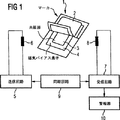
図1は、図式的に示された磁気機械式商品監視システムに関連し、本発明の原理により作られた共振器を有するマーカを、そのハウジングの上部を部分的にはがし、内部構成要素を明らかにして示している。
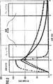
図2は、様々なQの値を持つ様々なマーカにより、駆動時に発生し、磁気機械式商品監視システムにおいて検出される信号を示している。
図3は、共振の鋭さQの関数として、第1のウィンドウの信号振幅と、第2のウィンドウの信号振幅との比率の関係を示している。
図4は、共振の鋭さQに対する第1の検出ウィンドウの信号振幅の関係を示しており、ここで、破線は、Qが人為的な処置で低下する時の関係を示しており、また様々な合金組成の値が、様々な記号を用いて示されている。
図5は、異方性磁界強度Hkの定義を説明するために、横方向の磁界での熱処理後に、本発明の原理により製作されたアモルファス磁気ひずみリボンが呈する代表的なB−Hループを示しており、さらに理想的な曲線を破線で示している。
図6は、本発明の原理により製作された共振器について、印加されたバイアス磁界の関数として、共振周波数と信号振幅との関係を示している。
図7は、本発明の原理により製作された共振器について、共振の鋭さQならびに信号振幅Aと印加されたバイアス磁界との関係を示している。
図8は、本発明の原理により製作された共振器について、6.5Oeのバイアス磁界と、この値よりも0.5Oeだけ大きいバイアス磁界と、0.5Oeだけ小さいバイアス磁界とについて、信号振幅と周波数との関係を示している。
図9は、本発明の原理により製作された共振器の起動状態と停止状態において、1.2kHzの間隔の重要性を例示するために、様々なバイアス磁界での共振曲線の重なりを示している。
図10は、共振器には200〜550のQの値が特に適している理由を例示するために、バースト・モードでの信号振幅と連続モードでの信号振幅の比率と、共振の鋭さQとの関係を示している。
好適な実施の形態の説明
図1は、共振器3と磁気バイアス素子4が入ったハウジング2とを備えたマーカ1を使用する、磁気機械式電子監視システムを示している。共振器3は、以下の化学式による組成を持つ、焼なまされたアモルファス磁気ひずみ合金のリボンから切り取られる。
FeaCobNicSixBy
ここで、a、b、c、x、yは原子%で表す値であって、好適な合金では、以下の値を取る:
15<a<30
79<a+b+c<85
b>12
30<c<50
この場合、xとyは、a+b+c+x+y=100となるようにその剰余を含み、また起動共振器は、100<Q<600の共振の鋭さを持ち、しかも、共振器が共振するように励振されてから約1ms後に約15db以下だけ小さくなり、また励振から約1ms後の信号振幅と比較して、励振から約7ms後に少なくとも15dBだけ小さくなる信号を発生する。共振器3は、100〜600の範囲、好ましくは500よりも小さく、また好ましくは200よりも大きい範囲に、鋭さQを持つ。バイアス素子4は、一般に1Oe〜10Oeの範囲内にある磁界強度を持つ予磁化磁界Hbを発生させる。バイアス素子4で発生する約6Oe〜7Oeの磁界強度Hbでは、共振器3は、その共振周波数の変化|dfr/dHb|<700Hz/Oeを示す。バイアス素子4を減磁させ、それにより、マーカ1を停止させると、共振器3の共振周波数は、少なくとも1.2kHzだけ変化する。共振器3は、少なくとも10Oeの異方性磁界Hkを持つ。
さらに、共振器3は、リボンの長手方向の広がりに対してほぼ直角で、かつリボンの平面内にある横方向の磁界の中で、共振器3が切り離されるリボンを焼なますことにより、共振器3のもっとも長い寸法と直角に設定された磁気異方性を有する。このことから、共振器3は、1Oe〜8Oeの予想動作範囲で直線のB−Hループを持つ。
さらに、共振器3は、図1に示す監視システムにおいて、マーカ1からのものとしてほぼ明瞭に識別できる信号を発生する。
図1に示す磁気機械式監視システムは、公知の方法で動作する。このシステムは、マーカ1に加えて、コイルまたはアンテナ6を有する送信回路5も含み、この送信回路は、例えば60Hzのパルス繰返し率で、58kHzといった所定の周波数のRFバーストを、それぞれのバーストとバーストの間に休止期間を置いて放出(送信)する。送信回路5は、同期回路9によって、前述のRFバーストを放出するように制御され、この同期回路9はまた、受信コイルまたはアンテナ8を有する受信回路7をも制御する。送信回路5を起動するときに、起動マーカ1、すなわち磁化されたバイアス素子4を有するマーカ1がコイル6とコイル8の間にある場合には、コイル6で放出されるRFバーストは、共振器3を、58kHz(この例において)の共振周波数で振動させ、それにより、図2に示されるタイプの信号を発生させる。図2は、共振の鋭さQの様々な値に対して、様々な信号を示している。
同期回路9は、受信回路7を起動して、図2において、ウィンドウ1と標示された第1の検出ウィンドウ内に、所定の周波数、この例においては58kHzの信号を受信するように、受信回路7を制御する。t=0の基準時間が図2に任意に示されており、ここでは、持続時間が約1.6msのRFバーストを放出するために、送信回路5が同期回路9により起動される。時間t=0は、このバーストの終わりと一致するように、図2では選択されている。t=0から約0.4ms後に、受信回路7が、ウィンドウ1内において起動される。ウィンドウ1の間(約1.7ms持続する)、受信回路7は、存在している所定の周波数(例えば、58kHz)のどんな信号も統合する。このウィンドウ1内の信号が、有効な統合結果をもたらすために、マーカ1で放出される信号は、励振時に比較的に大きい初期振幅(好ましくは、約100mVを超える)を持ち、また励振から約1ms後に、その初期振幅と比較して、約15dB以下だけ、好ましくは約10dB以下だけ減衰しなければならない。このことは、ウィンドウ1の中心付近では、約40mVの最小振幅を持たなければならないことを意味している。本発明による共振器は、以上の基準のすべてを満たす信号を発生させる。それぞれ、Q=50、Q=400、Q=800である共振器で発生する信号が、図2に記載されている。試験では、ウィンドウ1の信号(A1)を表す信号が励振から1ms後に測定され、またウィンドウ2の信号(A2)を表す信号が励振から7ms後に測定された。これらの時間は、それぞれのウィンドウの中心にくる時間である。
その後、同期回路9は受信回路7を停止させ、さらに1.7ms持続する第2の検出ウィンドウ(図2において、ウィンドウ2と標示されている)の間に、受信回路7を再起動させる。ウィンドウ2の間、受信回路7は、さらに所定の周波数(58kHz)のどんな信号でも統合する。この周波数の信号が、この時点において減衰のない信号を示す統合結果をもたらすようウィンドウ2に統合される場合には、受信回路7に入っている電気回路は、この信号が、起動マーカ1以外の発生源からのものであると想定する。
それゆえ、第2の検出ウィンドウにある信号の振幅が、最適な大きさであることが重要である。すなわち、この振幅は、マーカ1以外の発生源からのものと間違えられるほど大きすぎてはならず、第1のウィンドウにある信号と容易に区別できるほど十分に小さくなければならない。図2に見られるように、Q=50の共振器で発生する信号は、第1の検出ウィンドウにおいてすでにきわめて小さい振幅を示すくらい急速な減衰(リングダウン時間)を持っている。しかしながら、Q=800の共振器は、図2に示すとおり、第2の検出ウィンドウにおいて比較的大きい振幅をなおも示している。Q=400の本発明の共振器3で発生する信号は、ウィンドウ1とウィンドウ2のそれぞれにおいて、信頼できる検出を保証するに足る信号振幅を示すが、ただし、ウィンドウ1とウィンドウ2との信号振幅の差は、起動マーカ1からのものとして、この信号を確実に識別できるようにするくらい大きい。
図2は、共振の鋭さQと、それぞれウィンドウ1とウィンドウ2で検出された信号の比率との関係を示している。このような関係が弱まるにつれて、検出率が最適に高くなり、また誤り警報を最小限に抑えるという保証も高まる。実際には、ウィンドウ1で現れる信号と、ウィンドウ2で現れる信号との信号比率の最小減衰が約15dBであることが好ましい。これは、共振の鋭さQが600よりも小さく、好ましくは550よりも小さくなければならないことを意味している。しかしながら、第1の検出ウィンドウにおいて、妥当な信号振幅を得るためには、少なくとも100、好ましくは200の共振の鋭さQが必要となる。
受信回路7が、ウィンドウ1とウィンドウ2のそれぞれにおいて、上記の基準を満たす信号を検出する時には、警報器10がトリガされる。誤り警報を防止するため、送信回路5で放出されたバーストとバーストの間の所定数の連続休止期間(例えば、4つの連続する休止期間)中に、さらに前述の基準を満たす信号を検出するよう受信回路7に求めることができる。
マーカ1が無効に停止されているために、誤り警報が発生することもある。これは、マーカ1が停止されるとき、すなわちバイアス素子4が減磁されるときに現れるように、きわめて小さい予磁化磁界強度の存在のもとで、共振の鋭さQが、きわめて大きくなるためである。こういった事情のもとでは、共振の鋭さQは、1,000を超える値を取り、このことはバースト後の振動がきわめて長いことを示す。これは、無駄に停止されたマーカのウィンドウ1とウィンドウ2の信号振幅が、前述の検出基準を満たさず、従って警報器がまったくトリガされないことを意味している。
共振の鋭さQが、例えばリボンの穴のように、共振器3に対して不十分なリボン品質を呈する場合、例えば機械的な摩擦を生じさせる目的で人為的な処置を施した場合を含め、いくつかの異なる処置により下げられるか、あるいは共振器の厚みが、非常に大きくなり(例えば、30〜60μm)、その結果うず電流を誘導する場合がある。
一方、このような人為的な処置は、例えば同時に信号振幅に非常に悪影響を及ぼすことを含めて不利な副作用がある。図4に示す破線は、共振の鋭さQが、上記の処置により、人為的に、または強制的に下げられたときに発生する信号振幅の代表的な減少を表している。一方、このように信号振幅が減少すると、同時に監視システムの検出感度が低下する。
リボンの幅が6mmで、代表的なリボンの厚みが25μmであり、また組成が様々であるアモルファス・リボンを鋳造し、横方向の磁界の中で熱処理し、それらの共振作用を、6.5Oeの予磁化の定磁界の中で調査した。この目的のために、長さが38mmである条板を、パルスとパルスの間に16msの休止期間を置いて、1.6msの持続時間の交番磁界パルスを用いて励振した。これにより、これらの条板は、55kHz〜60kHzの範囲内で共振振動し、またこの範囲は、条板の長さをわずかに変えることにより58kHzに合わせることができた。鋭さQは、励振交番磁界を除去してから1ms後に信号振幅(図4において、信号1の振幅と標示されている)だけでなく、振動信号の減衰作用からも測定した。この信号は、100回の巻回数を持つピックアップ・コイルを用いて検出した。
表Iの模範的実施例1.A〜1.Jは、共振の鋭さQが最初から小さいいくつかの合金を示している。しかしながら、これらのサンプルは、共振器の素材に対して課せられた他の要求を満たしていない。
例1.Aと例1.Bは、無視できるほど小さい信号振幅を発生させた市販の合金を示している。これは、おそらく鋭さQが小さすぎる、すなわち100異化であることに起因し、またHk=5.5〜6A/cm(約7〜8Oe)において、これが、テスト用磁界強度Hb=5.2A/cm(=6.5Oe)のすぐ上にあっても、異方性磁界Hkの値が小さいことに起因している。
例1C〜例1Jは、上記のものよりも大きい異方性磁界強度Hkと、小さい鋭さQとの組み合わせに伴う大きい信号振幅を示している。しかしながら、これらのサンプルの欠点は、共振周波数frが、予磁化磁界Hbの厳密な値に大きく依存している点である。これらのサンプルでは、テスト用磁界強度Hbが、約1Oeだけ変化すると、共振周波数frは、1kHz、もしくはそれよりも著しく大きく変化する。このようなバイアス磁界Hbの変化は、例えば単にマーカを地磁気の下で様々な方向に向けるだけで発生しかねない。それに対応して、共振周波数が離調すると、このような条板を用いるマーカの検出精度がかなり低下する。
|dfr/dHb|の値は、一般に、焼なまし温度と焼なまし時間を調節することで変更できる。同一の焼なまし温度では、一般に、焼なまし時間が長くなると、|dfr/dHb|の値は小さくなる。とはいえ、これは、ある限度まで当てはまるにすぎない。例えば、表Iの合金のサンプルは、350℃で15分間すでに焼なまされており、その結果、|dfr/dHb|の値は、達成できる最小値に非常に近くなっていた。
熱処理プロセス、例えば、連続熱処理プロセスを経済的に実施するには、熱処理時間は、実質的に1分よりも短い、好ましくは秒の範囲にあることが要望される。さらに、このように短い熱処理時間は、焼なまされた材料が、所定の長さに切断可能なように、熱処理後もなお十分に延性があることも保証する。
表IIと表IIIは、所望の低周波数変化|dfr/dHb|を達成することのできた合金のサンプルを示している。これらのサンプルのすべてにおいて、熱処理パラメータは、|dfr/dHb|が、6.5Oeにて550〜650Hz/Oeという十分に小さい値を示すように選択した。
表IIと表IIIに示すサンプルからわかるように、合金の鉄含有量が減るにつれて、また合金のコバルドおよび/またはニッケルの含有量が増すにつれて、鋭さQの値が小さくなる。しかしながら、この材料をさらに励振して、十分に大きい振幅を持つ磁気弾性振動を発生させるように、約15原子%の一定の最小鉄含有量が必要である。鉄が約15原子%よりも少ない合金は、表Iのサンプル1.K〜1.Nで例示するとおり、磁気抵抗共振をまったく示さないか、あるいはほとんど示さない。
表Iの合金は、上で考察した所望の性質の少なくとも1つを欠いているため、その合金のどれもが共振器3としての使用にふさわしくない。
表IIと表IIIに示されるサンプルのうち、以下の合金のサンプルは、共振器3としての使用に適切な好ましい模範的実施例を示している。なぜなら、それらのサンプルは、500〜600よりも小さい鋭さQと、700Hz/Oeよりも小さい|dfr/dHb|値と、大きい信号振幅とを同時に達成しているからである。
表IIのサンプルII.1〜II.12は、コバルトの含有量の多いサンプルであって、これらは、非常に大きい信号振幅の点で区別される。サンプルII.1〜II.7が好ましい。
表IIIの例III.1〜III.31はすべて、前述の所望の特性を示しており、ここでは、例III.1〜III.22が好ましい。
表IIのサンプルII.A〜II.Cと、表IIIのサンプルIII.A〜III.Mは、600よりも大きい鋭さQを示すために、適切ではない。
Qの人為的な低下を表す前述の破線曲線と比較するために、図4は、本発明の合金組成を用いて、信号振幅を大幅に低下させずに、同時にQを小さくできることを示している。図4に示される例のすべては、それらの鋭さQが、機械的制動により、あるいは合金の組成に無関係な他の処置により、人為的に低下するときに、前述の適切でないサンプルよりも大きい信号振幅を示す。

上記の表から、以下の一般化された式の特性が確かめられる。これらの一般化により生成された合金はすべて、前述の所望の特性を示す。
さらに、以下の一般化はすべて、前述の一般式FeaCObNicSixByに基づいている。
コバルトの含有量は、最低32原子%になり、また鉄の含有量は少なくとも15原子%になり得る。この一般化された記述の範囲内の好適な実施例は、少なくとも43原子%、多くとも55原子%のコバルト含有量を持っている。前述の性質を示すさらに他の一般された一組の合金は、15原子%〜40原子%の鉄含有量を持っている。この一般された一組の合金の範囲内の、ある好適な実施例は、多くとも30原子%の鉄含有量、少なくとも15原子%のコバルト含有量および少なくとも10原子%のニッケル含有量を持っている。この一般化された一組の合金の範囲内の別の好適な実施例は、12原子%〜20原子%のコバルト含有量と、30原子%〜45原子%のニッケル含有量を持っている。
第3の一般化された一組の合金は、30原子%〜53原子%のニッケル含有量を持ち、ここで、鉄含有量は少なくとも15原子%であり、またコバルト含有量は少なくとも12原子%である。この一般化された一組の合金の範囲内の好適な実施例は、多くとも40原子%の鉄含有量を持っている。
最後に、別の一般化された一組の合金は、少なくとも10原子%のニッケル含有量、少なくとも15原子%の鉄含有量(ただし、多くとも42原子%)および18原子%〜32原子%のコバルト含有量を持っている。
ここに開示された共振器は、鉄、コバルト、ニッケル、シリコン、ホウ素だけから成る合金を用いて作られているが、前述の磁気的性質を大幅に変えることなく、モリブデン、ニオブ、クロム、マンガンなどの他の元素を、少ない原子の割合で添加であり、それゆえ、非常に少ない割合の上記追加元素を含む合金が、本発明の原理により鋳造できることが、アモルファス金属の分野の有識者には理解される。さらに、ガラス形成を促進するために、シリコン以外の元素(例えば、炭素と燐)を使用でき、それゆえ、ここに開示された共振器と合金が、このような他のガラス形成促進元素の存在を妨げないことも、アモルファス金属の分野の有識者にはわかる。
具体的に言えば、本発明により作られた合金は、上に指定した組成では示されてないが、0.2原子%〜0.6原子%の分量の炭素が入っているものと予想できる。この少量の炭素は、不純物として炭素が入っている鉄・ホウ素によって、また炭素が入っているるつぼ材料との当該融成物の化学反応により導かれる。炭素は、ガラス形成と磁気的性質に関して、ホウ素と同様な反応を示すから、このように非常に少量の炭素は、ホウ素向けのyの値に含められると見なすことができる。
上記のサンプルが切出されたリボンのすべてが、回転チルホイールを使用して、従来の方法で鋳造され、前述の組成を持つ融成物が、ノズルを通じて、この回転ホイールの環境に送られた。この鋳造リボンは、約20cmの長さの均一温度ゾーンを持つ長さ40cmの実験炉の中で、約300℃〜約400℃の範囲内の温度において、約0.2m/分〜4m/分の代表的な焼なまし速度で、連続的に焼なまされた(リール間焼なまし)。これは、この焼なまし温度において、約3秒〜約60秒の代表的な焼なまし時間に相当する。約1メートルの長さの均一温度ゾーンを持つ製造規模の炉では、この焼なまし速度は、それ相応の速さ(約1m/分〜20m/分)であると言える。
表IIと表IIIのサンプル用の焼なましパラメータを、6Oe〜7Oeの勾配が、550Hz/Oe〜650Hz/Oeに入るように調節した。表IIと表IIIのサンプル用の代表的な焼なまし条件は、約340℃〜約380℃の温度範囲であり、その場合、焼なまし速度は、短い実験炉の中で、約1〜3m/分、あるいは1メートルの長さの温度ゾーンを持つ製造炉では、5m/分〜15m/分であった。
リール間焼なましの結果、勾配が大きすぎたので、表Iのサンプルだけを、かなり長い時間(すなわち15分)の間、350℃で、バッチで焼なました。しかしながら、このように焼もどしを長引かせても、所望の勾配は得られなかった。
焼もどし中に使用された磁界は、リボンの長手方向に直角で、かつリボンの平面内にあった。この磁界の強度は、実験炉において約2kOe、また製造炉において1kOeであった。この磁界強度の主要な条件は、そのリボン(長手方向)の軸線に直角な磁界を飽和させることで十分である点である。リボンの幅にわたる代表的な減磁係数から判断すれば、少なくとも約数百Oeの磁界強度で十分であろう。
上述のとおり、長さ38mm、幅6mm、厚み約25μmのサンプルに対して、あらゆる試験が行われた。表IIと表IIIのリボンはすべて、問題なく、所望の長さに切断されるくらい十分な延性があった。
異方性磁界の強度Hkは、図5に示されるとおり、B−Hループ・トレーサで記録されたB−Hループから決定された。センス・コイル・システムは、B=Jを想定できるように、エアフラックスを補償した。
磁気音響的性質を決定するために、これらのサンプルを励振(駆動)して、約18mOeのピーク振幅の交流磁界バーストにより、様々なバイアス磁界にて共振させた。これらのバーストのオンタイムは、60Hzの繰返し率の約10分の1、すなわち、約1.6mmであった。これらの共振振幅は、巻回数100の密結合受信コイルを使用して、個々のバーストが終了してから1ms後と2ms後に測定された。値A1は、このバーストの終了から1ms後の信号振幅を示している。一般に、A1δN・W・Hacである。ここで、Nは受信コイルの巻回数であり、Wは共振器の幅であり、またHacは、励振(駆動)磁界の強度である。A1を発生させる上記因子の特定の組合せは重要でない。
共振の鋭さは、以下の関係により、各バーストの終了から1ms後と2ms後にそれぞれ発生する振幅A1とA2から、検証された信号の指数減衰を仮定して計算された:
Q=πfr/In(A1/A2)
周波数・バイアスの勾配は、6Oe〜7Oeに決定され、また停止時の周波数偏移は、その共振周波数を、6.5Oe(起動状態)と2Oe(停止状態用の磁界上限)で観測することで決定され、これらの磁界強度での共振周波数の差として計算された。
図5〜図8は、本発明により作られた共振器の磁気的および磁気弾性的な性質の代表的な特性を示している。これらの曲線は、横方向の磁界において、360℃にて、約6秒間焼なまされたFe24Co18Ni40Si2B16合金用のものである。このサンプルは、幅6mmで、厚み24μmである。この長さは、6.5Oeにて、厳密に58kHzで共振周波数を発生させるために、37.1mmに調節された。例示の目的で、約700Hz/Oeの上限に6Oe〜7Oeのバイアス磁界の勾配があり、また約10Oeの下限の周りに異方性磁界Hkがあるように、焼なまし条件を意図的に選択した。焼なまし温度を約340℃に変更すれば、同じ焼なまし速度において、約600Hz/Oeのさらに望ましい勾配が容易に得られることになるであろう。
図5は、50Hzにて記録されたB−Hループを示している。図5に示される破線は、横方向の異方性の理想的なループであって、異方性磁界Hkを定め、約10Oeにて現れる磁気飽和に接近するまで、このループが直線であることを実証するためのものである。
図6は、このサンプルの共振周波数と共振振幅A1を、バイアス磁界の関数として示している。図7は、このサンプルのQ値と、バイアス磁界との関係を示している。
起動状態では、共振器は、一般に6Oe〜7Oeの磁界を用いてバイアスされる。このバイアス磁界強度では、共振器は、大きい振幅と、550よりも小さいQを示す。一般に、上述の試験条件のもとでの振幅は、上述のとおり、調査システムにおいて有益な検出を行うために、最低約40mVとなる。
マーカは、バイアス磁界を減らすかまたは除去することで停止し、それにより共振周波数を高め、振幅を小さくしてQを大きくする。これは、バイアス素子4を減磁することで達成される。
図6から見られるとおり、共振周波数は、バイアス磁界強度によって決まる。実際には、目標値(ここでは、6.5Oeと仮定)からのバイアス磁界の代表的な変動は、約+/−0.5Oeとなる。このような変動は、地磁気に対するマーカの様々な向きから起こるか、あるいはバイアス素子4の特性のばらつきから起こる。共振器の素材自体も散乱を受けて、目標バイアス磁界にて、目標周波数を正確に示さない場合がある。このような理由で、共振器3を、その周波数・バイアス勾配があまりにも急勾配とならないように、設計しなければならない。
図8は、6.5Oeのバイアス磁界およびこの目標値から0.5Oe上、また0.5Oe下のバイアス磁界にて、周波数に対する共振振幅A1を示している。主として交流バーストのオンタイムだけでなく、共振器のQによっても決定される共振曲線の有限帯域幅により、共振器3は、たとえ共振周波数にぴったり合わなくても、58kHzの送信周波数において、なおも十分な信号を示している。図8に示されるとおり、周波数の変動が、このバイアス磁界において、1Oe当り約700Hzの変動である場合には、共振信号A1は、約40mVをさらに超える。不利な周波数変動が大きければ大きいほど、それだけ、有利な周波数変動が小さくなる。従って、起動マーカの共振曲線は、それらの振幅帯域幅の約2分の1以上も離れてはならない。こうして、周波数・バイアス磁界曲線|dfr/dHb|の勾配は、好ましくは、約700HZ/Oeよりも小さい。
バイアス磁界に伴なう周波数の変動も、共振器3を起動するバイアス磁界が約6Oe〜7Oeである理由の1つである。地磁気が、少なくともバイアス素子4の磁界強度の約10原子%よりも小さいように、バイアス磁界を選択せねばならない。Hbには、上限もある。より大きなHbを発生させるためには、バイアス素子4に対して、さらに多くのバイアス磁石材料が必要となり、このことから、マーカがさらに高価となる。第2に、Hbがさらに大きくなると、バイアス素子4と共振器3との間の磁気吸引力が大きくなり、これにより、マーカの向きに応じて、著しい制動(磁気吸引力対重力)が加わる場合がある。こうして、最適なバイアス磁界は、約6Oe〜7Oeの範囲内に定められる。
上述のとおり、共振器3の共振周波数は、バイアス磁界Hbを除去してマーカを停止させた時に、著しく変化することになろう。図9に示されるとおり、バイアス磁界を減らした際に、少なくとも約1.2kHzだけ共振周波数が変化するときには、様々なバイアス磁界での共振曲線の重なり部分を十分に引き離す。停止状態に対してこれら2つの曲線が与えられ、これらの曲線は、交流バースト磁界の2つの異なるレベルに相当する。この破線曲線は、前述の標準テストで一般に使用される18mOeの交流磁界強度におけるものであるが、一方別の曲線(停止状態用)は、送信コイル6に近い磁気機械式監視システムの質問ゾーンに発生し得る増大駆動磁界レベルに相当する。起動状態用に示される曲線は、18mOeの標準駆動磁界強度にて描かれた。
実際には、この停止は、バイアス素子4を減磁することで行われる。事実上、「減磁」バイアス素子4は、なお、わずかの磁化を示し、それにより約2Oeのバイアス磁界Hbを発生させる場合がある。それゆえ、テスト基準として、6.5Oeでの共振周波数と比較される2Oeでの共振周波数の周波数偏移は、共振器3が適正に停止させることができるように、少なくとも1.2kHzでなければならない。
しかしながら、前述のデータから、勾配|dfr/dHb|が小さくなるにつれて、停止時の周波数偏移も小さくなる。共振周波数は、所定の値から離れすぎるために、勾配が大きすぎると、ピックレートが小さくなるが、停止時に周波数偏移が小さすぎると、誤り警報が発生する。それゆえ、最適な妥協点を得なければならず、このような妥協点は、ピックレートが、激しく下がりだす700Hz/Oeの限度よりもかなり下にあるその勾配が約550Hz/Oe〜650Hz/Oeとなるように、合金の組成と熱処理を調節するものとして、ここで選択されてきた。このことから、周波数偏移を、確実に1.6kHzよりも大きくすることができ、この周波数偏移は、約400Hz/Oeの勾配と相関させることになる1.2kHzという誤り警報用の重要な値を著しく超える。
図10は、共振器3には約200〜550の共振器のQが特によく適している理由に関して、さらに他の情報を提供している。
すでに説明したとおり、共振器のQは、以下の式により共振器3のリングダウン時間を決定する:
A(t)=A(0)exp(−t・π・fr/Q)
励振中、共振器の信号は、同一時定数を、「リングアップ」するように求め、すなわち、励振直後の信号A(0)は、以下の式により与えられる:
A(0)=A∞(1−exp(−tONπfr/Q))
ここで、tONはバースト送信器のオンタイムであり、またA∞は「無限」励振時間後に得られることになる信号振幅である。実際には、「無限」とは、Q/πfrよりもずっと大きい時間尺度(一般に、数ミリ秒)をさす。振幅A∞は、磁気機械式監視システムで使用されるバースト・モードではなくて、連続モードで共振器を励振させる場合に測定される共振器の振幅である。
上記の両等式を組み合わせれば、振幅A1用の値、すなわち励振から1ms後に発生する振幅は以下のとおりとなる:
A(1ms)=A∞(1−exp(−tONπfr/Q))exp(−1msπfr/Q)
図10は、このような関係、すなわちA(1ms)/A∞とQ(t=1.7msの場合)との関係を描いており、200と550の間のQ値に、最大値があることを示している。これは、このようなQ値により、交流バーストが共振器を十分に励振するくらいリングダウン時間、従って、またリングアップ時間も確実に短くでき、同時に、第1の検出ウィンドウに統合するに足る信号を提供する程度にリングダウン時間を確実に長くできることを意味している。
磁気音響的性質は、その組成と焼なまし条件に敏感に反応する。素材のばらつき、すなわち目標組成からのわずかなずれは、焼なましパラメータを変えれば補償できる。これを、自動化されたやり方で試みる、すなわち焼なまし中に共振器の性質を測定し、それに応じて、焼なましパラメータを調節することは、非常に望ましい。しかしながら、連なったリボンの性質の観測から、短い共振器の磁気音響的性質が何であるのか、どのように結論を下してよいのか、または評価してよいのか、当初は明らかでない。
それにもかかわらず、上記のデータから、共振器の異方性磁界が、共振器の性質と密接に相関することが明らかになっている。共振器の異方性磁界と、連なったリボン上で測定された異方性磁界とは、減磁磁界だけ異なる。従って、連なったリボンの幅と厚みだけでなく、そのリボンの異方性磁界Hkもモニタでき、そのことから、減磁効果を加えることにより、共振器の異方性磁界Hkを計算することができる。これにより、自動化されたやり方で、焼なましパラメータ(例えば、焼なまし速度)を調節することができ、その結果、焼なまされた共振器素材の性質を再現性よく得ることができる。
他の変形や変更が、当業者で提案される場合があるが、妥当で、かつ適正に、この技術に対する発明者の貢献の範囲に属するあらゆる変更や変形を、ここに保証された特許の範囲内で実施することが、発明者の意図である。 Background of the Invention
Field of Invention
The present invention relates to an amorphous magnetostrictive alloy used for a marker used in a magnetomechanical electronic merchandise monitoring system. The present invention also relates to a magnetomechanical electronic merchandise monitoring system that uses the marker as well as a method of making an amorphous magnetostrictive alloy and a method of manufacturing the marker.
Description of prior art
Various types of electronic merchandise monitoring systems are known that have the common feature of using markers or tags attached to merchandise to be protected from theft, such as merchandise in the store. When legally purchasing a product, the marker is either removed from the product or converted from an activated state to a stopped state. Such systems typically use detection devices located at every outlet of the store, and if an activated marker passes through the detection system, this is detected by the detection system and an alarm is triggered. The
One type of electronic merchandise monitoring system is known as a harmonic system. In such a system, the marker is made of a ferromagnetic material, and its detection system generates an electromagnetic field at a predetermined frequency. When the magnetic marker passes through the electromagnetic field, the magnetic marker disturbs the electromagnetic field and generates harmonics of a predetermined frequency. This detection system is tuned to detect several harmonic frequencies. If such a harmonic frequency is detected, an alarm is triggered. The generated harmonic frequency is determined by the magnetic action of the magnetic material of the marker. Specifically, the harmonic frequency is determined by the degree to which the BH loop of the magnetic material deviates from the linear BH loop. In general, as the non-linearity of the BH loop of the magnetic material becomes stronger, more harmonics are generated. This type of system is disclosed, for example, in US Pat. No. 4,484,184.
However, there are two fundamental problems with such a harmonic system. The disturbance of the electromagnetic field caused by the marker is relatively short in range, and therefore can only be detected in a relatively close range of the marker itself. Therefore, if such a harmonic system is used in a commercial facility, this is the path defined by the electromagnetic transmitter on one side and the electromagnetic receiver on the other side, and the path through which the customer passes. Is limited to a maximum of about 90 cm. Yet another problem with such harmonic systems is to distinguish between harmonics generated by the marker ferromagnet and harmonics generated by other ferromagnets, such as keys, coins, and belt buckles. It is difficult.
As a result, another type of electronic merchandise monitoring system, known as a magnetomechanical system, has been developed. Such a system is described, for example, in US Pat. No. 4,510,489. In this type of system, the marker consists of an element of magnetostrictive material known as a resonator, made of a magnetizable material, placed near a strip known as a biasing element. Although not necessarily required, the resonator is usually made of an amorphous ferromagnet, and the bias element is made of a crystalline ferromagnet. The marker is activated by magnetizing the bias element and stopped by demagnetizing the bias element.
Such magneto-mechanical system detection devices include transmitters that send pulses in the form of RF bursts at a certain frequency within the low radio frequency range, for example 58 kHz. Pulses (bursts) are emitted (transmitted) with a pulse repetition rate of 60 Hz, for example, with a pause between successive pulses. The detection device includes a receiver that is synchronized (gated) with the transmitter so that it is only activated during the pauses between the pulses emitted by the transmitter. The receiver assumes that nothing is detected during such pauses between pulses. However, if there is an activation marker between the transmitter and the receiver, the resonator in this activation marker is excited with a transmission pulse and mechanically at this transmission frequency,
In order to further minimize false alarms caused, for example, by signals generated by other RF sources, the receiving circuit uses two detection windows within each pause period. The receiver integrates any existing signal, in this example 58 kHz, into the respective windows and compares the integration results of the respective signals integrated into those windows. Since the signal generated at the marker is an attenuating signal, if this detected signal is from a resonator in the marker, this signal will show an amplitude reduction (integration result) in the window. On the other hand, if the RF signal from another RF source has a predetermined resonance frequency at the same time, or has harmonics of the predetermined resonance frequency, in each window, substantially the same amplitude (integration result) ) Is expected. Therefore, the alarm is triggered only if the signals detected in both windows within the pause period exhibit the aforementioned amplitude reduction characteristics in each of several consecutive pause periods.
For this purpose, as described above, the receiving electronic device is synchronized with the transmitting electronic device by the synchronization circuit. The receiving electronic device is activated by the synchronization circuit in order to determine the presence of a signal of a predetermined resonance frequency in a first activation window about 1.7 ms after the end of each transmission pulse. In order to ensure the distinction between the signal integrated into this first window (if this signal is from a resonator) and the signal integrated into the second window, Then, a large signal amplitude is desirable. Thereafter, the receiving electronic device is stopped, and then the receiving electronic device is restarted in the second detection window about 6 ms after the excitation of the first resonator, and a signal having a predetermined resonance frequency is again obtained and integrated. If such signals are integrated to produce approximately the same result as the first detection window, the evaluation electronics will not detect that the signal detected in the first window is from the marker, but from the noise. Or consider it from some other external RF source. Therefore, the alarm is not triggered.
PCT applications WO 96/32731 and WO 96/32518 corresponding to US Pat. No. 5,469,489 are generally represented by the chemical formula CoaFebNicMdBeSifCgA glassy metal alloy is disclosed. In this chemical formula, M is selected from molybdenum and chromium, a, b, c, d, e, f, g are values expressed in atomic%, a is in the range of about 40 to about 43, and b is In the range of about 35 to about 42, c in the range of 0 to about 5, d in the range of 0 to about 3, e in the range of about 10 to about 25, and f in the range of 0 to about 15 And g is in the range of 0 to about 2. This alloy is cast into a ribbon by rapid solidification, annealed to enhance its magnetic properties, and processed into a marker particularly suitable for use in a magneto-mechanical commodity monitoring system. This marker is characterized by a relatively linear magnetization response in a frequency situation where the harmonic marker system operates magnetically. The voltage amplitude detected for this marker is large, and interference between monitoring systems based on mechanical resonance and harmonic re-radiation is eliminated.
U.S. Pat. No. 5,469,140 discloses a ribbon strip of amorphous magnetic alloy that is heat treated while applying a transverse saturation magnetic field. This heat-treated strip is used as a marker for an interrogation pulse type electronic merchandise monitoring system. Preferred materials for this strip are iron, cobalt, silicon, and boron, with the proportion of cobalt exceeding 30 atomic percent.
U.S. Pat. No. 5,252,144 proposes to anneal various magnetostrictive alloys to improve their ring-down characteristics. Nevertheless, this patent does not disclose applying a magnetic field during heating.
Despite these attempts, there is a need to develop magnetostriction markers that have optimal characteristics for use in magnetomechanical commodity surveillance systems and that are “invisible” to harmonic systems.
The problem with the characteristics of the conventional resonators used so far in such magneto-mechanical systems is that these resonators are driven with transmit pulses in order to facilitate integration into the first detection window. Immediately, it has been designed to generate a relatively large signal amplitude. From this, this resonator signal has a relatively long ring-down (attenuation) time, and therefore the resonator signal still has a relatively large amplitude when the second detection window appears. The detection sensitivity (reliability) of the integrated monitoring system is directly dependent on the difference in amplitude (integration result) of the resonator signals of these two consecutive detection windows. If this signal decay time is relatively slow, the difference in amplitude (integration result) between the resonator signals of the two detection windows may be small enough to fall within the normal variation range of the spurious signal. If this detector system is set (adjusted) to ignore such small differences as an alarm trigger operating criterion, it is truly the signal from the marker and thus the signal that should trigger the alarm. If so, the alarm will not be triggered. Alternatively, if the detector system is adjusted to handle such a relatively small difference as a condition to trigger the alarm, this will increase the frequency of false alarms.
Since both harmonic and magnetomechanical systems are in a commercial environment, yet another problem is known as “contamination”, which causes the marker to operate in certain systems. Although designed, it is a problem of generating false alarms in other types of systems. This problem occurs most commonly when a conventional marker triggers a false alarm in a harmonic system, even though it is intended for use in a magnetomechanical system. This occurs because, as described above, the markers in the harmonic system generate a detectable harmonic by having a non-linear BH loop. Markers with straight BH loops will be “invisible” to the harmonic monitoring system. However, non-straight BH loops are “standard” type BH loops that are shown magnetic. In order to produce a material with a straight BH loop, special measures need to be taken.
Yet another desirable feature of a resonator used for a marker in a magneto-mechanical monitoring system is that the resonant frequency of the resonator is less dependent on the premagnetization field strength generated by the bias element. This biasing element is used to activate and deactivate the marker and can therefore be easily magnetized and demagnetized. When the bias element is magnetized to activate the marker, the exact strength of the magnetic field generated by the bias element cannot be guaranteed. Therefore, at least within the specified magnetic field strength range, it is desirable that the resonance frequency of the resonator does not change significantly even for various magnetic field strengths. This is dfr/ DHbIndicates that must be small. Where frIs the resonance frequency and HbIs the strength of the magnetic field generated by the bias element.
However, when stopping the marker, it is desirable that the resonance frequency changes very greatly as the magnetic field is removed. For this reason, if the stop marker is left attached to a product, if it resonates, it will surely resonate at a resonance frequency that is far from the resonance frequency that is the detection target of the detection device.
Finally, the material used to make the resonator is a mechanical that allows the material of the resonator to be processed in bulk, i.e. usually allows heat treatment (annealing) to set the magnetic properties. Must have nature. Since amorphous metal is usually cast as a continuous ribbon, this means that it must exhibit sufficient ductility so that it can be processed in a continuous annealing furnace, and this means that the ribbon Means that it needs to be unwound from the pay-out reel, passed through an annealing furnace and possibly re-wound after annealing. In addition, since this annealed ribbon is usually cut into small strips and the strips are incorporated into the markers, this means that the material must be very brittle and its magnetic properties. However, once the annealing treatment is set, it means that even if the material is cut, it should not be altered or deteriorated.
Summary of invention
The object of the present invention is that it can be cut and processed into a rectangular and ductile magnetostrictive strip,bIs applied or removed to start or stop the strip, and when the strip is excited by an alternating magnetic field in the activated state, the resonance frequency frA mechanical resonance vibration in the longitudinal direction, i.e., a vibration that can be caused to have a relatively large signal amplitude after excitation, but then decay relatively quickly. It is an object of the present invention to provide a magnetostrictive amorphous metal alloy that is incorporated into a marker of a surveillance system.
In particular, an object of the present invention is to generate a vibration having a resonance frequency having an amplitude large enough to be detected in the first detection window in the magnetomechanical monitoring system during excitation, and the second detection window appears. It is an object of the present invention to provide the above-described magnetostrictive amorphous alloy that sufficiently attenuates the amplitude until time so that the vibration from the marker can be reliably distinguished from the spurious signal.
Still another object of the present invention is to provide a resonance frequency f when there is a change in the magnetization magnetic field strength.rIs to provide such an alloy with a slight change.
Yet another object is that when the marker resonator is switched from the activated state to the deactivated state, the resonance frequency frIt is an object of the present invention to provide the above alloy whose remarkably changes.
It is yet another object of the present invention to provide such an alloy that does not trigger an alarm in a harmonic monitoring system when incorporated into a marker for a magnetomechanical monitoring system.
The above object is achieved according to the invention by a resonator according to the principles of the invention, which consists of an amorphous magnetostrictive alloy having the general formula:
FeaCobNicSixBy
Here, a, b, c, x and y are values expressed in atomic%, and in a suitable alloy take the following values:
15 <a <30
79 <a + b + c <85
b> 12
30 <c <50
In this case, x and y include the remainder so that a + b + c + x + y = 100, and the activation resonator has a resonance sharpness of 100 <Q <600 and is linear B−H to a minimum magnetic field of about 8 Oe. The loop has an anisotropic magnetic field of at least about 10 Oe, and the signal about 7 ms after excitation is at least 15 dB compared to the amplitude of the signal about 1 ms after the resonator is excited to resonate. The amplitude is made small.
Further, typically 0 <x <8 and 10 <y <21.
In the above specified range, as used elsewhere, the smaller specified value and the larger specified value should all be interpreted as including the numerical value of the specified value itself, as if "about" In other words, a slight variation can be allowed from the indicated value literally.
A preferred embodiment of an alloy producing a ribbon having a width of about 13 mm is Fetwenty fourCo16Ni42Si2B16And Fetwenty fourCo16Ni42.7Si1.5B15.5C0.3And Fetwenty fiveCo15Ni43.5Si1B15.5A preferred embodiment for producing a ribbon having a width of 6 mm is Fetwenty fourCo18Ni40Si2B16And Fetwenty fourCo18Ni40.7Si1.5B15.5C0.3And Fetwenty fiveCo17Ni40.5Si1.5B16It is. Carbon is not described in the general formula of the invention shown at the outset, but very small amounts may be present. Since carbon acts like boron, it can be considered to be included in the specified boron content.
In addition to the above-described attributes, the above-described resonator generates a signal that is attenuated by 15 dB or less, preferably 10 dB or less, compared to the amplitude of the signal immediately after excitation, 1 ms after the resonator is excited.
This alloy is made by quenching from the molten state to produce an amorphous ribbon, which is then annealed in the temperature range of 300 ° C. to 400 ° C. for a time shorter than 60 seconds, The ribbon is subjected to a heat treatment and simultaneously a transverse magnetic field is applied to the ribbon. This magnetic field is a magnetic field that is substantially perpendicular to the (longest) spread in the longitudinal direction of the ribbon and is in the plane of the ribbon.
As mentioned above, the annealed alloy forming the resonator with the above composition has a straight BH loop until reaching the saturation region and its anisotropic magnetic field strength HkIs at least about 80 A / m (about 10 Oe). Thus, a marker having a strip cut from this ribbon will not trigger an alarm in the harmonic monitoring system because the magnetic anisotropy is set perpendicular to the strip.
The mechanical vibration signal A (t) generated by a strip cut from such a ribbon takes the following form when driven by a transmission pulse of a magnetomechanical monitoring system:
A (t) = A (0) · exp (−t · π · fr/ Q)
Here, A (0) is the initial amplitude, and Q is the sharpness of resonance. The alloys of the present invention have a Q less than about 500-600 and at least 100, preferably 200, so that the signal generated at the resonator initially has the desired large signal amplitude and then decays relatively quickly. It has been designed based on the recognition that it should be. The upper limit range of Q determines the maximum allowable decay time (ring-down time) in order to perform sufficient signal attenuation in the second detection window, and the lower limit range of Q is determined in the first detection window. Ensuring sufficient signal amplitude (when t is very small). An alloy having the composition shown above has a Q in its range, so that the signal amplitude is between the amplitude in the first detection window and the amplitude in the second window. Is about 15 dB.
In a resonator made of an alloy according to the above equation, the resonance frequency frChanges only slightly. Magnetic field strength HbIs in the range between 6 Oe and 7 Oe, the resonant frequency f for alloys with the above formularChange (expressed in absolute value) is | dfr/ DHb| <700 Hz / Oe.
The resonance frequency f of the alloy made by the above formularChanges at least 1.2 kHz when the marker is switched from the activated state to the deactivated state. This is large enough to prevent the marker from reliably generating a detectable signal in a stopped state.
Furthermore, a ribbon made of an alloy according to the above formula is sufficiently ductile to allow the ribbon to be wound, unwound, or cut into a strip without significantly changing the aforementioned properties.
A marker used in a magneto-mechanical monitoring system includes a resonator made of an alloy having the above formula and properties, housed in a housing, near a ferromagnetic biasing element. Such a marker includes a transmitter that emits a continuous RF burst of a predetermined frequency with a pause between bursts, and a detector that is tuned to detect a signal of a predetermined frequency. A synchronizing circuit that synchronizes the operation of the transmitting circuit and the receiving circuit, and that the receiving circuit is activated for the purpose of obtaining a signal of a predetermined frequency during a pause between bursts; Suitable for use in a magneto-mechanical monitoring system having an alarm that is triggered when a detection circuit detects a signal identified as being from a marker within at least one range of a pause in between. Preferably, an alarm is generated when a signal identified as being from the marker is detected within two or more rest periods. Due to the aforementioned nature of the marker made of an alloy having the above formula, the ring-down time of this marker has appropriate characteristics and whenever the system is reasonable for triggering the alarm, the alarm Can be set to trigger, and at the same time, false alarms are substantially minimized.
Description of drawings
FIG. 1 relates to a schematically shown magneto-mechanical commodity monitoring system, in which a marker having a resonator made according to the principles of the present invention is partially peeled off the top of its housing to reveal internal components. Is shown.
FIG. 2 shows signals generated during driving by various markers having various values of Q and detected in a magnetomechanical merchandise monitoring system.
FIG. 3 shows the ratio relationship between the signal amplitude of the first window and the signal amplitude of the second window as a function of the resonance sharpness Q.
FIG. 4 shows the relationship of the signal amplitude of the first detection window to the resonance sharpness Q, where the dashed line shows the relationship when Q is reduced by an artificial procedure, The alloy composition values are indicated using various symbols.
FIG. 5 shows the anisotropic magnetic
FIG. 6 shows the relationship between resonant frequency and signal amplitude as a function of applied bias field for a resonator fabricated according to the principles of the present invention.
FIG. 7 shows the relationship between resonance sharpness Q and signal amplitude A and applied bias field for a resonator fabricated according to the principles of the present invention.
FIG. 8 shows the signal amplitude for a resonator fabricated according to the principles of the present invention for a bias field of 6.5 Oe, a bias field greater than this value by 0.5 Oe, and a bias field smaller by 0.5 Oe. The relationship with frequency is shown.
FIG. 9 shows the overlap of the resonance curves at various bias fields to illustrate the importance of the 1.2 kHz spacing in the activated and deactivated states of a resonator fabricated according to the principles of the present invention. .
FIG. 10 illustrates the ratio of the signal amplitude in the burst mode to the signal amplitude in the continuous mode and the sharpness of the resonance Q to illustrate why a Q value between 200 and 550 is particularly suitable for the resonator. Shows the relationship.
DESCRIPTION OF PREFERRED EMBODIMENTS
FIG. 1 shows a magnetomechanical electronic monitoring system that uses a
FeaCobNicSixBy
Here, a, b, c, x, y are values expressed in atomic%, and in a suitable alloy, take the following values:
15 <a <30
79 <a + b + c <85
b> 12
30 <c <50
In this case, x and y include the remainder so that a + b + c + x + y = 100, and the start-up resonator has a resonance sharpness of 100 <Q <600, and is excited so that the resonator resonates. After about 1 ms, the signal is reduced by about 15 db or less, and compared with the signal amplitude after about 1 ms after excitation, a signal is generated that is reduced by at least 15 dB after about 7 ms after excitation. The resonator 3 has a sharpness Q in the range of 100 to 600, preferably less than 500, and preferably greater than 200. The
Furthermore, the resonator 3 is resonated by annealing the ribbon from which the resonator 3 is disconnected in a transverse magnetic field that is substantially perpendicular to the longitudinal extent of the ribbon and in the plane of the ribbon. It has a magnetic anisotropy set perpendicular to the longest dimension of the vessel 3. From this, the resonator 3 has a linear BH loop in an expected operation range of 1 Oe to 8 Oe.
Furthermore, the resonator 3 generates a signal that can be almost clearly identified as from the
The magnetomechanical monitoring system shown in FIG. 1 operates in a known manner. In addition to the
The synchronizing
Thereafter, the
Therefore, it is important that the amplitude of the signal in the second detection window is an optimal magnitude. That is, this amplitude must not be too great to be mistaken for a source other than
FIG. 2 shows the relationship between the resonance sharpness Q and the ratio of the signals detected in
When the receiving circuit 7 detects a signal satisfying the above-mentioned criteria in each of the
Since the
When the resonance sharpness Q exhibits insufficient ribbon quality with respect to the resonator 3, such as a ribbon hole, for example, including the case where an artificial treatment is performed for the purpose of causing mechanical friction, It can be lowered by several different treatments, or the thickness of the resonator can become very large (eg, 30-60 μm), resulting in eddy currents.
On the other hand, such an artificial treatment has disadvantageous side effects including, for example, a very bad influence on the signal amplitude at the same time. The broken line shown in FIG. 4 represents a typical decrease in the signal amplitude that occurs when the resonance sharpness Q is artificially or forcibly lowered by the above procedure. On the other hand, when the signal amplitude decreases in this way, the detection sensitivity of the monitoring system decreases at the same time.
Amorphous ribbons having a ribbon width of 6 mm, a typical ribbon thickness of 25 μm, and various compositions are cast and heat-treated in a transverse magnetic field, and their resonance action is 6.5 Oe. The pre-magnetization was investigated in a constant magnetic field. For this purpose, a strip 38 mm long was excited with alternating magnetic field pulses of 1.6 ms duration with a 16 ms rest period between the pulses. As a result, these strips oscillated at resonance within the range of 55 kHz to 60 kHz, and this range could be adjusted to 58 kHz by slightly changing the length of the strips. The sharpness Q was measured not only from the signal amplitude (labeled as the amplitude of the
Exemplary Example of Table I A-1. J indicates some alloys whose resonance sharpness Q is small from the beginning. However, these samples do not meet the other requirements imposed on the resonator material.
Example 1. A and Example 1. B shows a commercially available alloy that generated a negligibly small signal amplitude. This is probably due to the sharpness Q being too small,
Examples 1C to 1J show an anisotropic magnetic field strength H greater than that described above.kAnd a large signal amplitude associated with a combination with a small sharpness Q. However, the disadvantage of these samples is that the resonant frequency frIs the pre-magnetization magnetic field HbIt depends on the exact value of. In these samples, the test magnetic field strength HbChanges by about 1 Oe, the resonant frequency frVaries significantly at 1 kHz or significantly more. Such a bias magnetic field HbThis change can occur, for example, simply by pointing the marker in various directions under geomagnetism. Correspondingly, when the resonance frequency is detuned, the detection accuracy of the marker using such a strip is considerably lowered.
Dfr/ DHbThe value of | can generally be changed by adjusting the annealing temperature and the annealing time. At the same annealing temperature, in general, if the annealing time is long,r/ DHbThe value of | becomes smaller. However, this is only true up to a certain limit. For example, a sample of the alloy in Table I has already been annealed at 350 ° C. for 15 minutes, resulting in | dfr/ DHbThe value of | was very close to the minimum achievable.
In order to economically carry out a heat treatment process, for example a continuous heat treatment process, it is desired that the heat treatment time is substantially shorter than 1 minute, preferably in the range of seconds. Furthermore, such a short heat treatment time also ensures that the annealed material is still sufficiently ductile after the heat treatment so that it can be cut to a predetermined length.
Tables II and III show the desired low frequency change | dfr/ DHbA sample of an alloy that can achieve |. In all of these samples, the heat treatment parameter is | dfr/ DHbWas selected to show a sufficiently small value of 550 to 650 Hz / Oe at 6.5 Oe.
As can be seen from the samples shown in Tables II and III, the value of the sharpness Q decreases as the iron content of the alloy decreases and as the cobalt and / or nickel content of the alloy increases. However, a constant minimum iron content of about 15 atomic% is required to further excite this material to generate magnetoelastic vibrations with sufficiently large amplitude. Alloys with less than about 15 atomic percent iron are listed in
None of the alloys in Table I are suitable for use as resonator 3 because they lack at least one of the desired properties discussed above.
Of the samples shown in Tables II and III, the following alloy samples show preferred exemplary embodiments suitable for use as resonator 3. Because those samples have sharpness Q less than 500-600 and less than 700 Hz / Oe | dfr/ DHbThis is because the | value and the large signal amplitude are achieved simultaneously.
Sample II of Table II. 1-2. 12 are samples with high cobalt content, which are distinguished in terms of very large signal amplitudes. Sample II. 1-2. 7 is preferred.
Example III in Table III. 1-III. 31 all exhibit the desired properties described above, where Example III. 1-III. 22 is preferred.
Sample II of Table II. A to II. C and Sample III of Table III. A to III. M is not appropriate because it exhibits a sharpness Q greater than 600.
For comparison with the previously described dashed curve representing an artificial reduction in Q, FIG. 4 shows that using the alloy composition of the present invention, Q can be simultaneously reduced without significantly reducing signal amplitude. . All of the examples shown in FIG. 4 show that when their sharpness Q is artificially reduced by mechanical braking or by other treatments unrelated to the composition of the alloy, a signal that is greater than the aforementioned unsuitable samples. Indicates the amplitude.
From the above table, the properties of the following generalized equation can be confirmed. All alloys produced by these generalizations exhibit the desired properties described above.
In addition, all of the following generalizations are for the general formula FeaCObNicSixByBased on.
The cobalt content can be at least 32 atomic percent and the iron content can be at least 15 atomic percent. Preferred embodiments within the scope of this generalized description have a cobalt content of at least 43 atomic percent and at most 55 atomic percent. Yet another common set of alloys exhibiting the aforementioned properties has an iron content of 15 atomic percent to 40 atomic percent. One preferred embodiment within this general set of alloys has an iron content of at most 30 atomic percent, a cobalt content of at least 15 atomic percent and a nickel content of at least 10 atomic percent. Yes. Another preferred embodiment within this generalized set of alloys has a cobalt content of 12 atomic percent to 20 atomic percent and a nickel content of 30 atomic percent to 45 atomic percent.
The third generalized set of alloys has a nickel content of 30 atomic% to 53 atomic%, where the iron content is at least 15 atomic% and the cobalt content is at least 12 atomic%. It is. Preferred embodiments within this generalized set of alloys have an iron content of at most 40 atomic percent.
Finally, another generalized set of alloys has a nickel content of at least 10 atomic percent, an iron content of at least 15 atomic percent (but at most 42 atomic percent) and 18 atomic percent to 32 atomic percent. Has a cobalt content.
The resonator disclosed here is made using an alloy consisting only of iron, cobalt, nickel, silicon, and boron, but without significantly changing the aforementioned magnetic properties, molybdenum, niobium, chromium, manganese Those skilled in the field of amorphous metals understand that other elements such as, for example, may be added in a small atomic proportion and therefore alloys containing a very small proportion of these additional elements can be cast according to the principles of the present invention. Is done. In addition, elements other than silicon (eg, carbon and phosphorus) can be used to promote glass formation, and therefore the resonators and alloys disclosed herein are present in the presence of such other glass formation promoting elements. It is also understood by experts in the field of amorphous metals that it does not interfere with this.
Specifically, an alloy made in accordance with the present invention is not shown in the composition specified above, but can be expected to contain an amount of carbon between 0.2 atomic% and 0.6 atomic%. . This small amount of carbon is introduced by iron / boron containing carbon as an impurity and by chemical reaction of the melt with the crucible material containing carbon. Since carbon exhibits a similar reaction to boron with respect to glass formation and magnetic properties, it can be assumed that such very small amounts of carbon are included in the value of y for boron.
All of the ribbons from which the above samples were cut were cast in a conventional manner using a rotating chill wheel, and a melt having the composition described above was sent through a nozzle to the environment of the rotating wheel. . The cast ribbon is about 0.2 m / min to 4 m / min at a temperature in the range of about 300 ° C. to about 400 ° C. in a 40 cm long experimental furnace with a uniform temperature zone of about 20 cm in length. Continuous annealing at a typical annealing speed (inter-reel annealing). This corresponds to a typical annealing time of about 3 seconds to about 60 seconds at this annealing temperature. In a production scale furnace with a uniform temperature zone of about 1 meter in length, this annealing speed can be said to be a corresponding speed (about 1 m / min to 20 m / min).
The annealing parameters for the samples in Table II and Table III were adjusted so that the gradient from 6 Oe to 7 Oe was within 550 Hz / Oe to 650 Hz / Oe. Typical annealing conditions for the samples in Table II and Table III are in the temperature range of about 340 ° C. to about 380 ° C., where the annealing rate is about 1 to about 1 in a short experimental furnace. In a production furnace having a temperature zone of 3 m / min or 1 meter in length, it was 5 m / min to 15 m / min.
As a result of the inter-reel annealing, the gradient was too great, so only the samples in Table I were batch annealed at 350 ° C. for a fairly long time (
The magnetic field used during tempering was perpendicular to the length of the ribbon and in the plane of the ribbon. The strength of this magnetic field was about 2 kOe in the experimental furnace and 1 kOe in the production furnace. The main condition for this magnetic field strength is that it is sufficient to saturate the magnetic field perpendicular to the ribbon (longitudinal) axis. Judging from typical demagnetization factors across the width of the ribbon, a magnetic field strength of at least about several hundred Oe will be sufficient.
As described above, all tests were performed on samples having a length of 38 mm, a width of 6 mm, and a thickness of about 25 μm. All of the ribbons in Tables II and III were ductile enough to be cut to the desired length without problems.
Strength of anisotropic magnetic field HkWas determined from the BH loop recorded with the BH loop tracer, as shown in FIG. The sense coil system compensated for the air flux so that B = J could be assumed.
To determine the magnetoacoustic properties, these samples were excited (driven) and resonated at various bias fields with an alternating magnetic field burst with a peak amplitude of about 18 mOe. The on-time of these bursts was about one tenth of the 60 Hz repetition rate, or about 1.6 mm. These resonant amplitudes were measured 1 ms and 2 ms after the end of each burst using a tightly coupled receiver coil with 100 turns. The value A1 indicates the signal amplitude after 1 ms from the end of this burst. Generally, A1δN · W · HacIt is. Where N is the number of turns of the receiving coil, W is the width of the resonator, and HacIs the intensity of the excitation (drive) magnetic field. The particular combination of the above factors that generates A1 is not important.
The sharpness of the resonance was calculated from the amplitudes A1 and A2 occurring 1 ms and 2 ms after the end of each burst, assuming the exponential decay of the verified signal, according to the following relationship:
Q = πfr/ In (A1 / A2)
The frequency / bias gradient is determined to be 6 Oe to 7 Oe, and the frequency shift during stop is determined by observing the resonance frequency at 6.5 Oe (starting state) and 2 Oe (upper limit magnetic field for stopping state). Determined and calculated as the difference in resonant frequency at these magnetic field strengths.
5-8 illustrate typical characteristics of the magnetic and magnetoelastic properties of a resonator made in accordance with the present invention. These curves are for Fe annealed at 360 ° C. for approximately 6 seconds in a transverse magnetic field.twenty fourCo18Ni40Si2B16For alloys. This sample has a width of 6 mm and a thickness of 24 μm. This length was adjusted to 37.1 mm to generate a resonant frequency at exactly 58 kHz at 6.5 Oe. For illustrative purposes, there is a 6 Oe-7 Oe bias field gradient at the upper limit of about 700 Hz / Oe and an anisotropic magnetic field H around the lower limit of about 10 Oe.kAnnealing conditions were deliberately selected so that there is. Changing the annealing temperature to about 340 ° C. would easily provide a more desirable gradient of about 600 Hz / Oe at the same annealing rate.
FIG. 5 shows a BH loop recorded at 50 Hz. The broken line shown in FIG. 5 is an ideal anisotropy loop in the lateral direction, and the anisotropic magnetic field HkTo demonstrate that this loop is straight until it approaches the magnetic saturation that appears at about 10 Oe.
FIG. 6 shows the resonance frequency and resonance amplitude A1 of this sample as a function of the bias magnetic field. FIG. 7 shows the relationship between the Q value of this sample and the bias magnetic field.
In the activated state, the resonator is typically biased using a magnetic field between 6 Oe and 7 Oe. At this bias field strength, the resonator exhibits a large amplitude and a Q less than 550. In general, the amplitude under the test conditions described above will be at least about 40 mV to provide useful detection in the survey system, as described above.
The marker stops by reducing or eliminating the bias field, thereby increasing the resonant frequency, decreasing the amplitude, and increasing Q. This is achieved by demagnetizing the
As can be seen from FIG. 6, the resonance frequency is determined by the bias magnetic field strength. In practice, the typical variation of the bias magnetic field from the target value (here assumed to be 6.5 Oe) is about +/− 0.5 Oe. Such fluctuations occur from various orientations of the marker with respect to geomagnetism or from variations in the characteristics of the
FIG. 8 shows the resonance amplitude A1 with respect to frequency at a bias magnetic field of 6.5 Oe and a bias magnetic field 0.5 Oe above and 0.5 Oe below this target value. Due to the finite bandwidth of the resonance curve, which is mainly determined not only by the on-time of the AC burst, but also by the Q of the resonator, the resonator 3 is still at a transmission frequency of 58 kHz, even if it does not exactly match the resonance frequency. Shows enough signal. As shown in FIG. 8, when the frequency variation is about 700 Hz per Oe in this bias magnetic field, the resonance signal A1 further exceeds about 40 mV. The greater the unfavorable frequency variation, the smaller the advantageous frequency variation. Thus, the resonance curves of the activation markers should not be more than about one-half of their amplitude bandwidth. Thus, the frequency / bias magnetic field curve | dfr/ DHbThe slope of | is preferably less than about 700 HZ / Oe.
The fluctuation of the frequency accompanying the bias magnetic field is one of the reasons why the bias magnetic field for starting the resonator 3 is about 6 Oe to 7 Oe. The bias magnetic field must be selected so that the geomagnetism is at least less than about 10 atomic% of the magnetic field strength of the
As described above, the resonance frequency of the resonator 3 depends on the bias magnetic field H.bWhen the marker is removed and the marker is stopped, it will change significantly. As shown in FIG. 9, when the resonance frequency changes by at least about 1.2 kHz when the bias magnetic field is reduced, the overlapping portions of the resonance curves at various bias magnetic fields are sufficiently separated. These two curves are given for the resting state, and these curves correspond to two different levels of the alternating burst magnetic field. This dashed curve is at the 18 mOe AC field strength commonly used in the standard test described above, while the other curve (for the stop state) is in the interrogation zone of the magnetomechanical monitoring system close to the
Actually, this stop is performed by demagnetizing the
However, from the above data, the slope | dfr/ DHbAs | becomes smaller, the frequency shift at the time of stopping also becomes smaller. Since the resonance frequency is too far from a predetermined value, if the gradient is too large, the pick rate is reduced, but if the frequency deviation is too small at the time of stop, an error alarm is generated. Therefore, an optimum compromise must be obtained, such a compromise being that the slope is about 550 Hz / Oe to 650 Hz / Oe, where the pick rate is well below the 700 Hz / Oe limit where it begins to fall drastically. Has been selected here to adjust the composition and heat treatment of the alloy. This ensures that the frequency deviation can be greater than 1.6 kHz, which is important for false alarms of 1.2 kHz that will correlate with a slope of about 400 Hz / Oe. The value is significantly exceeded.
FIG. 10 provides further information on why a resonator Q of about 200-550 is particularly well suited for resonator 3.
As already explained, the Q of the resonator determines the ring-down time of the resonator 3 according to the following formula:
A (t) = A (0) exp (−t · π · fr/ Q)
During excitation, the resonator signal is determined to “ring up” with the same time constant, ie, the signal A (0) immediately after excitation is given by:
A (0) = A∞(1-exp (-tONπfr/ Q))
Where tONIs the on-time of the burst transmitter, and A∞Is the signal amplitude to be obtained after an “infinite” excitation time. Actually, “infinity” means Q / πfrA much larger time scale (typically a few milliseconds). Amplitude A∞Is the amplitude of the resonator measured when exciting the resonator in continuous mode rather than the burst mode used in magnetomechanical monitoring systems.
Combining the above equations, the value for the amplitude A1, ie the amplitude that occurs 1 ms after excitation, is as follows:
A (1 ms) = A∞(1-exp (-tONπfr/ Q)) exp (-1msπfr/ Q)
FIG. 10 shows such a relationship, that is, A (1 ms) / A∞And Q (when t = 1.7 ms), the Q value between 200 and 550 has a maximum value. This is because such a Q value ensures that the ring-down time, and therefore also the ring-up time, is short enough that the AC burst sufficiently excites the resonator, and at the same time a signal sufficient to be integrated into the first detection window. This means that the ring-down time can be made long enough to provide
Magnetoacoustic properties are sensitive to their composition and annealing conditions. Material variations, i.e., slight deviations from the target composition, can be compensated by changing the annealing parameters. It is highly desirable to try this in an automated manner, ie to measure the properties of the resonator during annealing and to adjust the annealing parameters accordingly. However, it is not initially clear from observations of the properties of the connected ribbons what the magnetoacoustic properties of a short resonator are, how it can be concluded or evaluated.
Nevertheless, the above data reveals that the anisotropic magnetic field of the resonator is closely correlated with the properties of the resonator. The anisotropy field of the resonator differs from the anisotropy field measured on the continuous ribbon by only the demagnetization field. Therefore, not only the width and thickness of the continuous ribbon, but also the anisotropic magnetic field H of the ribbon.kTherefore, by adding a demagnetizing effect, the anisotropic magnetic field H of the resonator can be monitored.kCan be calculated. This allows the annealing parameters (e.g., annealing speed) to be adjusted in an automated manner, resulting in reproducible properties of the annealed resonator material.
Other variations and modifications may be suggested by one skilled in the art, but all changes and variations that fall within the scope of the inventor's contribution to this technology are reasonable and reasonably warranted here. It is the inventor's intention to carry out within.
Claims (16)
該共振器はFeaCObNicSixByの組成を持つ焼なまされたアモルファス磁気ひずみ合金を備え、
ここで、a、b、c、x、yは原子%で表す値であって、a+b+c+x+y=100であり、前記合金は
1)aが15〜30、bが少なくとも12、cが30〜50そして79<a+b+c<85である合金群、
2)aが少なくとも15で、bが少なくとも32である合金群、
3)aが15〜40である合金群、および
4)aが15〜42、bが18〜32そしてcが少なくとも10であるか、aが少なくとも15、bが少なくとも12そしてcが30〜53である合金群
から選ばれ、
更に8Oeの最小磁界強度まで直線的なB−Hループ、100〜600の鋭さQ、少なくとも10Oeの異方性磁界Hkを持ち、しかも、バイアス磁界Hbが存在する状態で共振するように励振されたときに、励振から約1ms後の振幅が、励振直後の前記信号の振幅よりも15dB以下だけ小さく、また励振から7ms後の振幅が、励振から1ms後の前記振幅よりも少なくとも15dBだけ小さい機械的共振周波数frの信号を発生させ、かつ
前記機械的共振周波数f r が、前記バイアス磁界H b の磁界強度に応じて変化することと、
H b が6〜7Oeの場合に、|df r /dH b |が700Hz/Oeよりも小さいことと、
前記バイアス磁界が除去されたときに機械的共振周波数が少なくとも1.2kHzだけ変化することと
を特徴とする共振器。A resonator used for a marker of a magnetomechanical electronic commodity monitoring system,
The resonator comprises a Fe a CO b Ni c Si x B y annealed by amorphous magnetostrictive alloy having a composition of,
Here, a, b, c, x, y are values expressed in atomic%, and a + b + c + x + y = 100, and the alloy is 1) a is 15 to 30, b is at least 12, c is 30 to 50, and Alloy group with 79 <a + b + c <85,
2) an alloy group wherein a is at least 15 and b is at least 32;
3) an alloy group in which a is 15-40, and 4) a is 15-42, b is 18-32 and c is at least 10, a is at least 15, b is at least 12, and c is 30-53. Selected from the alloy group
More linear B-H loop up to a minimum field strength of 8 Oe, sharpness Q of 100 to 600, has an anisotropy field H k of at least 10 Oe, moreover, the excitation to resonate in a state where the bias magnetic field H b is present The amplitude after about 1 ms after excitation is less than 15 dB less than the amplitude of the signal immediately after excitation, and the amplitude after 7 ms after excitation is at least 15 dB less than the amplitude after 1 ms after excitation. to generate a signal of a mechanical resonance frequency f r, and
And said mechanical resonance frequency f r changes according to the magnetic field strength of the bias magnetic field H b,
When H b is 6 to 7 Oe , | df r / dH b | is smaller than 700 Hz / Oe;
A resonator wherein the mechanical resonance frequency changes by at least 1.2 kHz when the bias magnetic field is removed .
10Oe以下のバイアス磁界を発生させるバイアス素子と、
前記バイアス素子に近接して配置された、請求項1〜11の1つに記載の共振器と、
前記バイアス素子と前記共振器を封入するハウジングと
を備えることを特徴とするマーカ。A marker used in a magnetomechanical electronic product monitoring system,
A bias element that generates a bias magnetic field of 10 Oe or less;
A resonator according to one of claims 1 to 11 , arranged close to the bias element;
A marker comprising: the bias element and a housing enclosing the resonator.
2)前記マーカを励振し、前記共振器を機械的に共振させて、共振周波数の前記信号を放出させる送信手段と、
3)前記共振周波数の前記共振器からの前記信号を受け取って、統合する受信手段と、
4)前記受信手段を起動して、前記共振器からの前記共振周波数の前記信号を、前記送信手段による前記共振器の励振から0.4ms後に始まる第1の検出ウィンドウに、また前記送信手段による前記共振器の励振から7ms後に始まる第2の検出ウィンドウに受け取って統合する、前記送信手段と前記受信手段に接続された同期手段と、
5)警報器と
を含み、
前記受信手段は、前記第2の検出ウィンドウに統合された前記共振器からの前記共振周波数の前記信号が、前記第1の検出ウィンドウに統合された前記共振器からの前記共振周波数の前記信号よりも事実上小さい場合に前記警報器をトリガする手段を備える
ことを特徴とする磁気機械式の電子商品監視システム。1) A marker according to claim 12 ;
2) transmitting means for exciting the marker and mechanically resonating the resonator to emit the signal at a resonant frequency;
3) receiving means for receiving and integrating the signal from the resonator at the resonant frequency;
4) Activating the receiving means and causing the signal at the resonant frequency from the resonator to enter a first detection window starting 0.4 ms after excitation of the resonator by the transmitting means, and by the transmitting means Receiving means for integrating into a second detection window starting 7 ms after excitation of the resonator, and synchronizing means connected to the receiving means;
5) including alarms,
The receiving means is configured such that the signal of the resonance frequency from the resonator integrated in the second detection window is greater than the signal of the resonance frequency from the resonator integrated in the first detection window. And a means for triggering the alarm device when it is substantially small.
請求項1記載の共振器用の組成を持つアモルファス磁気ひずみ合金を準備する工程と、
前記アモルファス磁気ひずみ合金を、横方向の磁界の中で、かつ300〜400℃の範囲の温度で、1分よりも短い間、焼きなます工程と
を含むことを特徴とする方法。A method of making a resonator used in a magnetomechanical electronic product monitoring system,
Preparing an amorphous magnetostrictive alloy having the composition for a resonator according to claim 1;
Annealing the amorphous magnetostrictive alloy in a transverse magnetic field and at a temperature in the range of 300-400 ° C. for less than 1 minute.
請求項14記載の方法で共振器を製造する工程と、
前記共振器を、磁化された強誘電性バイアス素子の近くに配置する工程と、
前記バイアス素子と前記共振器をハウジング内に封入する工程と
を含むことを特徴とする方法。A method of making a marker used in a magnetomechanical electronic merchandise monitoring system,
Producing a resonator by the method of claim 14 ;
Placing the resonator near a magnetized ferroelectric bias element;
And enclosing the bias element and the resonator in a housing.
Applications Claiming Priority (3)
| Application Number | Priority Date | Filing Date | Title |
|---|---|---|---|
| US08/890,723 US5841348A (en) | 1997-07-09 | 1997-07-09 | Amorphous magnetostrictive alloy and an electronic article surveillance system employing same |
| US08/890,723 | 1997-09-07 | ||
| PCT/EP1998/004053 WO1999013442A1 (en) | 1997-07-09 | 1998-07-01 | Amorphous magnetostrictive alloy and an electronic article surveillance system employing same |
Publications (3)
| Publication Number | Publication Date |
|---|---|
| JP2002510417A JP2002510417A (en) | 2002-04-02 |
| JP2002510417A5 JP2002510417A5 (en) | 2006-01-05 |
| JP4101307B2 true JP4101307B2 (en) | 2008-06-18 |
Family
ID=25397063
Family Applications (1)
| Application Number | Title | Priority Date | Filing Date |
|---|---|---|---|
| JP51497999A Expired - Lifetime JP4101307B2 (en) | 1997-07-09 | 1998-07-01 | Magnetomechanical electronic commodity monitoring system, marker used in the system, resonator used for the marker, method for manufacturing the resonator, and method for manufacturing the marker |
Country Status (10)
| Country | Link |
|---|---|
| US (1) | US5841348A (en) |
| EP (2) | EP0996942B1 (en) |
| JP (1) | JP4101307B2 (en) |
| KR (1) | KR100582580B1 (en) |
| AT (2) | ATE304197T1 (en) |
| DE (2) | DE69834282T2 (en) |
| DK (1) | DK1562160T3 (en) |
| ES (1) | ES2263146T3 (en) |
| PT (1) | PT1562160E (en) |
| WO (1) | WO1999013442A1 (en) |
Families Citing this family (19)
| Publication number | Priority date | Publication date | Assignee | Title |
|---|---|---|---|---|
| US6011475A (en) | 1997-11-12 | 2000-01-04 | Vacuumschmelze Gmbh | Method of annealing amorphous ribbons and marker for electronic article surveillance |
| US6254695B1 (en) * | 1998-08-13 | 2001-07-03 | Vacuumschmelze Gmbh | Method employing tension control and lower-cost alloy composition annealing amorphous alloys with shorter annealing time |
| US6199309B1 (en) * | 1998-10-06 | 2001-03-13 | Contempo Card Company, Inc. | Merchandising markers accomodating anti-theft sensor |
| US6181249B1 (en) * | 1999-01-07 | 2001-01-30 | Sensormatic Electronics Corporation | Coil driving circuit for EAS marker deactivation device |
| US6359563B1 (en) * | 1999-02-10 | 2002-03-19 | Vacuumschmelze Gmbh | ‘Magneto-acoustic marker for electronic article surveillance having reduced size and high signal amplitude’ |
| US6645314B1 (en) | 2000-10-02 | 2003-11-11 | Vacuumschmelze Gmbh | Amorphous alloys for magneto-acoustic markers in electronic article surveillance having reduced, low or zero co-content and method of annealing the same |
| KR20030013068A (en) * | 2001-08-07 | 2003-02-14 | 정한영 | Apparatus and method for deactivating magnetic markers in an electromagnetic article surveillance sytem |
| EP1481378B1 (en) * | 2002-02-01 | 2008-03-19 | Datalogic Scanning, Inc. | Systems and methods for data reading and eas tag sensing and deactivating at retail checkout |
| US6783072B2 (en) | 2002-02-01 | 2004-08-31 | Psc Scanning, Inc. | Combined data reader and electronic article surveillance (EAS) system |
| US6854647B2 (en) * | 2002-02-01 | 2005-02-15 | Ncr Corporation | Checkout device including integrated barcode reader, scale, and EAS system |
| US6749695B2 (en) * | 2002-02-08 | 2004-06-15 | Ronald J. Martis | Fe-based amorphous metal alloy having a linear BH loop |
| US7527198B2 (en) | 2002-03-18 | 2009-05-05 | Datalogic Scanning, Inc. | Operation monitoring and enhanced host communications in systems employing electronic article surveillance and RFID tags |
| US6830634B2 (en) * | 2002-06-11 | 2004-12-14 | Sensormatic Electronics Corporation | Method and device for continuous annealing metallic ribbons with improved process efficiency |
| US7585459B2 (en) * | 2002-10-22 | 2009-09-08 | Höganäs Ab | Method of preparing iron-based components |
| US7619527B2 (en) | 2005-02-08 | 2009-11-17 | Datalogic Scanning, Inc. | Integrated data reader and electronic article surveillance (EAS) system |
| DE102005062016A1 (en) * | 2005-12-22 | 2007-07-05 | Vacuumschmelze Gmbh & Co. Kg | Deposit goods e.g. tin security mark, has sensor strips parameter of which indicates magnetizing force, and the permeability is changed to specified factor within specified range by magnetizing force |
| DE102006047022B4 (en) | 2006-10-02 | 2009-04-02 | Vacuumschmelze Gmbh & Co. Kg | Display element for a magnetic anti-theft system and method for its production |
| JP2008097459A (en) * | 2006-10-13 | 2008-04-24 | Takaya Corp | Device for monitoring electronic object |
| WO2017221099A1 (en) | 2016-06-23 | 2017-12-28 | 3M Innovative Properties Company | Magneto-mechanical marker with enhanced frequency stability and signal strength |
Family Cites Families (9)
| Publication number | Priority date | Publication date | Assignee | Title |
|---|---|---|---|---|
| US4268325A (en) * | 1979-01-22 | 1981-05-19 | Allied Chemical Corporation | Magnetic glassy metal alloy sheets with improved soft magnetic properties |
| US4484184A (en) * | 1979-04-23 | 1984-11-20 | Allied Corporation | Amorphous antipilferage marker |
| US4510489A (en) * | 1982-04-29 | 1985-04-09 | Allied Corporation | Surveillance system having magnetomechanical marker |
| US4667185A (en) * | 1985-12-06 | 1987-05-19 | Minnesota Mining And Manufacturing Company | Wireless synchronization system for electronic article surveillance system |
| US5252144A (en) * | 1991-11-04 | 1993-10-12 | Allied Signal Inc. | Heat treatment process and soft magnetic alloys produced thereby |
| US5568125A (en) * | 1994-06-30 | 1996-10-22 | Sensormatic Electronics Corporation | Two-stage annealing process for amorphous ribbon used in an EAS marker |
| US5469140A (en) * | 1994-06-30 | 1995-11-21 | Sensormatic Electronics Corporation | Transverse magnetic field annealed amorphous magnetomechanical elements for use in electronic article surveillance system and method of making same |
| US5628840A (en) * | 1995-04-13 | 1997-05-13 | Alliedsignal Inc. | Metallic glass alloys for mechanically resonant marker surveillance systems |
| US5539380A (en) * | 1995-04-13 | 1996-07-23 | Alliedsignal Inc. | Metallic glass alloys for mechanically resonant marker surveillance systems |
-
1997
- 1997-07-09 US US08/890,723 patent/US5841348A/en not_active Expired - Lifetime
-
1998
- 1998-07-01 ES ES05010323T patent/ES2263146T3/en not_active Expired - Lifetime
- 1998-07-01 PT PT05010323T patent/PT1562160E/en unknown
- 1998-07-01 EP EP98939591A patent/EP0996942B1/en not_active Expired - Lifetime
- 1998-07-01 DE DE69834282T patent/DE69834282T2/en not_active Expired - Lifetime
- 1998-07-01 WO PCT/EP1998/004053 patent/WO1999013442A1/en active IP Right Grant
- 1998-07-01 AT AT98939591T patent/ATE304197T1/en not_active IP Right Cessation
- 1998-07-01 EP EP05010323A patent/EP1562160B1/en not_active Expired - Lifetime
- 1998-07-01 DE DE69831492T patent/DE69831492T2/en not_active Expired - Lifetime
- 1998-07-01 JP JP51497999A patent/JP4101307B2/en not_active Expired - Lifetime
- 1998-07-01 DK DK05010323T patent/DK1562160T3/en active
- 1998-07-01 AT AT05010323T patent/ATE323925T1/en not_active IP Right Cessation
- 1998-07-01 KR KR1020007000165A patent/KR100582580B1/en not_active IP Right Cessation
Also Published As
| Publication number | Publication date |
|---|---|
| PT1562160E (en) | 2006-08-31 |
| EP0996942A1 (en) | 2000-05-03 |
| DE69831492D1 (en) | 2005-10-13 |
| KR20010021607A (en) | 2001-03-15 |
| DE69834282D1 (en) | 2006-05-24 |
| ATE323925T1 (en) | 2006-05-15 |
| EP0996942B1 (en) | 2005-09-07 |
| DE69831492T2 (en) | 2006-06-29 |
| DK1562160T3 (en) | 2006-08-21 |
| US5841348A (en) | 1998-11-24 |
| JP2002510417A (en) | 2002-04-02 |
| KR100582580B1 (en) | 2006-05-24 |
| DE69834282T2 (en) | 2007-04-12 |
| ATE304197T1 (en) | 2005-09-15 |
| EP1562160B1 (en) | 2006-04-19 |
| ES2263146T3 (en) | 2006-12-01 |
| WO1999013442A1 (en) | 1999-03-18 |
| EP1562160A1 (en) | 2005-08-10 |
Similar Documents
| Publication | Publication Date | Title |
|---|---|---|
| JP4101307B2 (en) | Magnetomechanical electronic commodity monitoring system, marker used in the system, resonator used for the marker, method for manufacturing the resonator, and method for manufacturing the marker | |
| JP4370001B2 (en) | Resonator used as marker for magneto-mechanical electronic merchandise monitoring system and method for manufacturing the same | |
| EP0696784B1 (en) | Magnetomechanical article surveillance marker with a tunable resonant frequency | |
| EP0915440B1 (en) | Transverse magnetic field annealed amorphous magnetomechanical elements for use in electronic article surveillance system and method of making same | |
| JP3955624B2 (en) | Metallic glass alloy for mechanical resonance marker monitoring system | |
| JP5276246B2 (en) | Annealed amorphous alloys for magnetoacoustic markers | |
| JP5227369B2 (en) | Magnetoacoustic marker for electronic merchandise monitoring | |
| EP1109941B1 (en) | Method for annealing an amorphous alloy and method for manufacturing a marker | |
| JP3955623B2 (en) | Metallic glass alloys for monitoring devices with mechanically resonating markers | |
| KR100576075B1 (en) | Metallic glass alloys for mechanically resonant marker surveillance systems | |
| JP4091664B2 (en) | Magneto-electronic article monitoring marker, magneto-electronic article monitoring system, and magnetostrictive element forming method | |
| KR100478114B1 (en) | Metallic glass alloys for mechanically resonant marker surveillance systems | |
| AU738871B2 (en) | Transverse magnetic field annealed amorphous magnetomechanical elements for use in electronic article surveillance system and method of making same | |
| EP0895208A2 (en) | Transverse magnetic field annealed amorphous magnetomechanical elements for use in electronic article surveillance system and method of making same |
Legal Events
| Date | Code | Title | Description |
|---|---|---|---|
| A521 | Request for written amendment filed |
Free format text: JAPANESE INTERMEDIATE CODE: A523 Effective date: 20050628 |
|
| A621 | Written request for application examination |
Free format text: JAPANESE INTERMEDIATE CODE: A621 Effective date: 20050628 |
|
| A131 | Notification of reasons for refusal |
Free format text: JAPANESE INTERMEDIATE CODE: A131 Effective date: 20070619 |
|
| A601 | Written request for extension of time |
Free format text: JAPANESE INTERMEDIATE CODE: A601 Effective date: 20070918 |
|
| A602 | Written permission of extension of time |
Free format text: JAPANESE INTERMEDIATE CODE: A602 Effective date: 20071029 |
|
| A601 | Written request for extension of time |
Free format text: JAPANESE INTERMEDIATE CODE: A601 Effective date: 20071016 |
|
| A602 | Written permission of extension of time |
Free format text: JAPANESE INTERMEDIATE CODE: A602 Effective date: 20071126 |
|
| A521 | Request for written amendment filed |
Free format text: JAPANESE INTERMEDIATE CODE: A523 Effective date: 20071116 |
|
| TRDD | Decision of grant or rejection written | ||
| A01 | Written decision to grant a patent or to grant a registration (utility model) |
Free format text: JAPANESE INTERMEDIATE CODE: A01 Effective date: 20080219 |
|
| A61 | First payment of annual fees (during grant procedure) |
Free format text: JAPANESE INTERMEDIATE CODE: A61 Effective date: 20080319 |
|
| FPAY | Renewal fee payment (event date is renewal date of database) |
Free format text: PAYMENT UNTIL: 20110328 Year of fee payment: 3 |
|
| R150 | Certificate of patent or registration of utility model |
Free format text: JAPANESE INTERMEDIATE CODE: R150 |
|
| FPAY | Renewal fee payment (event date is renewal date of database) |
Free format text: PAYMENT UNTIL: 20110328 Year of fee payment: 3 |
|
| S531 | Written request for registration of change of domicile |
Free format text: JAPANESE INTERMEDIATE CODE: R313531 |
|
| S533 | Written request for registration of change of name |
Free format text: JAPANESE INTERMEDIATE CODE: R313533 |
|
| FPAY | Renewal fee payment (event date is renewal date of database) |
Free format text: PAYMENT UNTIL: 20110328 Year of fee payment: 3 |
|
| R350 | Written notification of registration of transfer |
Free format text: JAPANESE INTERMEDIATE CODE: R350 |
|
| RD02 | Notification of acceptance of power of attorney |
Free format text: JAPANESE INTERMEDIATE CODE: R3D02 |
|
| FPAY | Renewal fee payment (event date is renewal date of database) |
Free format text: PAYMENT UNTIL: 20120328 Year of fee payment: 4 |
|
| FPAY | Renewal fee payment (event date is renewal date of database) |
Free format text: PAYMENT UNTIL: 20130328 Year of fee payment: 5 |
|
| FPAY | Renewal fee payment (event date is renewal date of database) |
Free format text: PAYMENT UNTIL: 20140328 Year of fee payment: 6 |
|
| R250 | Receipt of annual fees |
Free format text: JAPANESE INTERMEDIATE CODE: R250 |
|
| R250 | Receipt of annual fees |
Free format text: JAPANESE INTERMEDIATE CODE: R250 |
|
| R250 | Receipt of annual fees |
Free format text: JAPANESE INTERMEDIATE CODE: R250 |
|
| R250 | Receipt of annual fees |
Free format text: JAPANESE INTERMEDIATE CODE: R250 |
|
| R250 | Receipt of annual fees |
Free format text: JAPANESE INTERMEDIATE CODE: R250 |
|
| EXPY | Cancellation because of completion of term |