JP4101225B2 - Electronic apparatus, information processing apparatus, control method therefor, computer program, and computer-readable storage medium - Google Patents
Electronic apparatus, information processing apparatus, control method therefor, computer program, and computer-readable storage medium Download PDFInfo
- Publication number
- JP4101225B2 JP4101225B2 JP2004304344A JP2004304344A JP4101225B2 JP 4101225 B2 JP4101225 B2 JP 4101225B2 JP 2004304344 A JP2004304344 A JP 2004304344A JP 2004304344 A JP2004304344 A JP 2004304344A JP 4101225 B2 JP4101225 B2 JP 4101225B2
- Authority
- JP
- Japan
- Prior art keywords
- electronic device
- image
- unit
- information
- code
- Prior art date
- Legal status (The legal status is an assumption and is not a legal conclusion. Google has not performed a legal analysis and makes no representation as to the accuracy of the status listed.)
- Expired - Fee Related
Links
Images


Classifications
-
- H—ELECTRICITY
- H04—ELECTRIC COMMUNICATION TECHNIQUE
- H04N—PICTORIAL COMMUNICATION, e.g. TELEVISION
- H04N1/00—Scanning, transmission or reproduction of documents or the like, e.g. facsimile transmission; Details thereof
- H04N1/44—Secrecy systems
- H04N1/4406—Restricting access, e.g. according to user identity
- H04N1/4413—Restricting access, e.g. according to user identity involving the use of passwords, ID codes or the like, e.g. PIN
-
- H—ELECTRICITY
- H04—ELECTRIC COMMUNICATION TECHNIQUE
- H04N—PICTORIAL COMMUNICATION, e.g. TELEVISION
- H04N1/00—Scanning, transmission or reproduction of documents or the like, e.g. facsimile transmission; Details thereof
- H04N1/0035—User-machine interface; Control console
- H04N1/00352—Input means
- H04N1/00355—Mark-sheet input
- H04N1/00358—Type of the scanned marks
- H04N1/00363—Bar codes or the like
-
- H—ELECTRICITY
- H04—ELECTRIC COMMUNICATION TECHNIQUE
- H04N—PICTORIAL COMMUNICATION, e.g. TELEVISION
- H04N1/00—Scanning, transmission or reproduction of documents or the like, e.g. facsimile transmission; Details thereof
- H04N1/00962—Input arrangements for operating instructions or parameters, e.g. updating internal software
- H04N1/00968—Input arrangements for operating instructions or parameters, e.g. updating internal software by scanning marks on a sheet
-
- H—ELECTRICITY
- H04—ELECTRIC COMMUNICATION TECHNIQUE
- H04N—PICTORIAL COMMUNICATION, e.g. TELEVISION
- H04N1/00—Scanning, transmission or reproduction of documents or the like, e.g. facsimile transmission; Details thereof
- H04N1/44—Secrecy systems
- H04N1/4406—Restricting access, e.g. according to user identity
- H04N1/4433—Restricting access, e.g. according to user identity to an apparatus, part of an apparatus or an apparatus function
-
- H—ELECTRICITY
- H04—ELECTRIC COMMUNICATION TECHNIQUE
- H04W—WIRELESS COMMUNICATION NETWORKS
- H04W12/00—Security arrangements; Authentication; Protecting privacy or anonymity
- H04W12/03—Protecting confidentiality, e.g. by encryption
- H04W12/033—Protecting confidentiality, e.g. by encryption of the user plane, e.g. user's traffic
-
- H—ELECTRICITY
- H04—ELECTRIC COMMUNICATION TECHNIQUE
- H04L—TRANSMISSION OF DIGITAL INFORMATION, e.g. TELEGRAPHIC COMMUNICATION
- H04L63/00—Network architectures or network communication protocols for network security
- H04L63/04—Network architectures or network communication protocols for network security for providing a confidential data exchange among entities communicating through data packet networks
- H04L63/0428—Network architectures or network communication protocols for network security for providing a confidential data exchange among entities communicating through data packet networks wherein the data content is protected, e.g. by encrypting or encapsulating the payload
-
- H—ELECTRICITY
- H04—ELECTRIC COMMUNICATION TECHNIQUE
- H04N—PICTORIAL COMMUNICATION, e.g. TELEVISION
- H04N1/00—Scanning, transmission or reproduction of documents or the like, e.g. facsimile transmission; Details thereof
- H04N1/00127—Connection or combination of a still picture apparatus with another apparatus, e.g. for storage, processing or transmission of still picture signals or of information associated with a still picture
- H04N1/00281—Connection or combination of a still picture apparatus with another apparatus, e.g. for storage, processing or transmission of still picture signals or of information associated with a still picture with a telecommunication apparatus, e.g. a switched network of teleprinters for the distribution of text-based information, a selective call terminal
- H04N1/00307—Connection or combination of a still picture apparatus with another apparatus, e.g. for storage, processing or transmission of still picture signals or of information associated with a still picture with a telecommunication apparatus, e.g. a switched network of teleprinters for the distribution of text-based information, a selective call terminal with a mobile telephone apparatus
-
- H—ELECTRICITY
- H04—ELECTRIC COMMUNICATION TECHNIQUE
- H04N—PICTORIAL COMMUNICATION, e.g. TELEVISION
- H04N2101/00—Still video cameras
-
- H—ELECTRICITY
- H04—ELECTRIC COMMUNICATION TECHNIQUE
- H04N—PICTORIAL COMMUNICATION, e.g. TELEVISION
- H04N2201/00—Indexing scheme relating to scanning, transmission or reproduction of documents or the like, and to details thereof
- H04N2201/0077—Types of the still picture apparatus
- H04N2201/0084—Digital still camera
-
- H—ELECTRICITY
- H04—ELECTRIC COMMUNICATION TECHNIQUE
- H04N—PICTORIAL COMMUNICATION, e.g. TELEVISION
- H04N2201/00—Indexing scheme relating to scanning, transmission or reproduction of documents or the like, and to details thereof
- H04N2201/32—Circuits or arrangements for control or supervision between transmitter and receiver or between image input and image output device, e.g. between a still-image camera and its memory or between a still-image camera and a printer device
- H04N2201/3201—Display, printing, storage or transmission of additional information, e.g. ID code, date and time or title
- H04N2201/3204—Display, printing, storage or transmission of additional information, e.g. ID code, date and time or title of data relating to a user, sender, addressee, machine or electronic recording medium
-
- H—ELECTRICITY
- H04—ELECTRIC COMMUNICATION TECHNIQUE
- H04N—PICTORIAL COMMUNICATION, e.g. TELEVISION
- H04N2201/00—Indexing scheme relating to scanning, transmission or reproduction of documents or the like, and to details thereof
- H04N2201/32—Circuits or arrangements for control or supervision between transmitter and receiver or between image input and image output device, e.g. between a still-image camera and its memory or between a still-image camera and a printer device
- H04N2201/3201—Display, printing, storage or transmission of additional information, e.g. ID code, date and time or title
- H04N2201/3269—Display, printing, storage or transmission of additional information, e.g. ID code, date and time or title of machine readable codes or marks, e.g. bar codes or glyphs
-
- H—ELECTRICITY
- H04—ELECTRIC COMMUNICATION TECHNIQUE
- H04N—PICTORIAL COMMUNICATION, e.g. TELEVISION
- H04N2201/00—Indexing scheme relating to scanning, transmission or reproduction of documents or the like, and to details thereof
- H04N2201/32—Circuits or arrangements for control or supervision between transmitter and receiver or between image input and image output device, e.g. between a still-image camera and its memory or between a still-image camera and a printer device
- H04N2201/3201—Display, printing, storage or transmission of additional information, e.g. ID code, date and time or title
- H04N2201/328—Processing of the additional information
- H04N2201/3281—Encryption; Ciphering
-
- H—ELECTRICITY
- H04—ELECTRIC COMMUNICATION TECHNIQUE
- H04W—WIRELESS COMMUNICATION NETWORKS
- H04W12/00—Security arrangements; Authentication; Protecting privacy or anonymity
- H04W12/60—Context-dependent security
- H04W12/69—Identity-dependent
- H04W12/77—Graphical identity
-
- H—ELECTRICITY
- H04—ELECTRIC COMMUNICATION TECHNIQUE
- H04W—WIRELESS COMMUNICATION NETWORKS
- H04W28/00—Network traffic management; Network resource management
- H04W28/16—Central resource management; Negotiation of resources or communication parameters, e.g. negotiating bandwidth or QoS [Quality of Service]
- H04W28/18—Negotiating wireless communication parameters
-
- H—ELECTRICITY
- H04—ELECTRIC COMMUNICATION TECHNIQUE
- H04W—WIRELESS COMMUNICATION NETWORKS
- H04W84/00—Network topologies
- H04W84/02—Hierarchically pre-organised networks, e.g. paging networks, cellular networks, WLAN [Wireless Local Area Network] or WLL [Wireless Local Loop]
- H04W84/10—Small scale networks; Flat hierarchical networks
- H04W84/12—WLAN [Wireless Local Area Networks]
Landscapes
- Engineering & Computer Science (AREA)
- Signal Processing (AREA)
- Multimedia (AREA)
- Computer Security & Cryptography (AREA)
- Computer Networks & Wireless Communication (AREA)
- Computer Vision & Pattern Recognition (AREA)
- Studio Devices (AREA)
Description
本発明は、バーコードや2次元コード等の情報コードを光学的に読み取る機能を備えた光学的情報読取装置及びそれらの情報コードの出力装置に関する。 The present invention relates to an optical information reading device having a function of optically reading an information code such as a bar code or a two-dimensional code, and an output device for the information code.
近年、携帯電話やデジタルカメラなどの携帯端末が高機能化し、ネットワークに接続できる端末も増えている。しかしこれらの携帯端末は操作部材が限られているため、たとえばネットワークにアクセスするためのIDやパスワードなどのパラメータを入力する作業はきわめて面倒である。また、これらのパラメータの設定に関してはある程度ネットワークの知識が必要とされるため、ネットワークの知識に乏しいユーザにとって設定そのものが困難である。 In recent years, mobile terminals such as mobile phones and digital cameras have become highly functional, and an increasing number of terminals can be connected to a network. However, since these mobile terminals have limited operation members, for example, it is very troublesome to input parameters such as an ID and a password for accessing the network. In addition, since some knowledge of the network is required for setting these parameters, it is difficult for users who lack network knowledge to set the parameters themselves.
そこで、これらパラメータをユーザが入力することなく設定する方法の1つとして、携帯端末に情報コード読み取り機能を付加することによって、これらのパラメータを情報コードに変換して出力された表示装置に対して、ユーザは携帯端末の情報コード読み取り機能を使って読み込ませることで、設定するものが考えられる。 Therefore, as one of the methods for setting these parameters without input by the user, by adding an information code reading function to the portable terminal, these parameters are converted into information codes and output to the display device. The user can set the information by reading it using the information code reading function of the portable terminal.
光学的情報読取装置のシステムパラメータを設定する方法として、これらのパラメータを情報コードの一つである2次元バーコード(QRコード)に変換したものを読み込むことで自動的に設定する技術がある(特許文献1)。
しかしながら、たとえばネットワークに接続するためのパスワードなどの機密パラメータを前述の方法で読み込み装置に設定する場合、携帯端末の情報コード読み取り機能を有する携帯端末であればどの端末でも、コードを読み込むだけで機密パラメータを保持し設定することができ、セキュリティの面で問題がある。 However, for example, when setting a confidential parameter such as a password for connecting to a network in the reading device by the above-described method, any mobile terminal having a mobile terminal information code reading function can be confidential only by reading the code. Parameters can be retained and set, which is problematic in terms of security.
本発明は、このような課題に鑑みてなされたものであって、簡単な作業で、且つ、セキュリティ面でも安全に、電子機器に設定するためのパラメータを生成する技術を提供しようとするものである。 The present invention has been made in view of such problems, and it is an object of the present invention to provide a technique for generating a parameter for setting an electronic device in a simple operation and safely in terms of security. is there.
この課題を解決するため、例えば本発明の情報処理装置は以下の構成を備える。すなわち、
撮像手段と、パラメータに従って処理する処理手段とを備える電子機器用の前記パラメータを作成する情報処理装置であって、
前記電子機器用のパラメータを入力する入力手段と、
設定対象と成り得る電子機器が有する操作スイッチに対応する画像と、前記操作スイッチに対応するコード情報を記憶する電子機器情報記憶手段と、
設定対象となる電子機器を選択する選択手段と、
選択された電子機器に対応する前記画像とコード情報とを、前記電子機器情報記憶手段から取得する取得手段と、
前記取得手段で取得された画像を表示し、表示された画像中の操作スイッチに対応するコード情報を用いてコードを生成するコード生成手段と、
該入力手段で入力されたパラメータを、前記コード生成手段で生成されたコードを用いて暗号化し、暗号化情報を生成する暗号化手段と、
該暗号化手段で得られた暗号化情報に基づき、前記電子機器の前記撮像手段で撮像するための可視画像を生成し、出力する画像出力手段とを備える。
In order to solve this problem, for example, an information processing apparatus of the present invention has the following configuration. That is,
An information processing apparatus for creating the parameter for an electronic device including an imaging unit and a processing unit that processes according to the parameter,
Input means for inputting parameters for the electronic device;
An electronic device information storage means for storing an image corresponding to an operation switch included in an electronic device that can be set, and code information corresponding to the operation switch;
A selection means for selecting an electronic device to be set;
Obtaining means for obtaining the image and code information corresponding to the selected electronic device from the electronic device information storage means;
Code generating means for displaying an image acquired by the acquiring means and generating code using code information corresponding to an operation switch in the displayed image;
An encryption unit that encrypts the parameter input by the input unit using the code generated by the code generation unit and generates encryption information;
And an image output unit that generates and outputs a visible image to be captured by the imaging unit of the electronic device based on the encryption information obtained by the encryption unit.
本発明によれば、簡単な作業で、且つ、セキュリティ面でも安全に、電子機器に設定するためのパラメータを生成することが可能になる。 According to the present invention, it is possible to generate a parameter for setting an electronic device with simple work and safely in terms of security.
以下、添付図面に従って本発明に係る実施形態を詳細に説明する。 Hereinafter, embodiments according to the present invention will be described in detail with reference to the accompanying drawings.
なお、実施形態では、設定情報の入力及び出力装置としてパーソナルコンピュータ(PC)、被設定装置として光学的情報コード読み込むことが可能なデジタルカメラに適用した例を説明する。 In the embodiment, an example will be described in which the present invention is applied to a personal computer (PC) as a setting information input / output device and a digital camera capable of reading an optical information code as a device to be set.
<デジタルカメラの構成の説明>
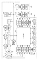
図1は実施形態におけるデジタルカメラのブロック構成図である。デジタルカメラ100は、光学系(撮像用レンズ)10を介して被写体像を撮影するように構成されている。光学系10は、ズームレンズ(撮影画角を変更可能なレンズ)として構成されうる。これにより光学的なズーム機能(いわゆる光学ズーム)が提供されている。デジタルカメラ100は、更に、撮像素子14によって撮像される画像を電子的に切り取る(トリミング)ことによる電子的なズーム機能(いわゆる電子ズーム)を有するように構成されうる。なお、デジタルカメラ100は、光学ズーム及び電子ズームのいずれか一方の機能のみを有するように構成される場合もある。また、光学系10は、交換可能であってもよく、この場合は、デジタルカメラ100の本体側から光学系10に対して電気信号を送ることにより、光学系10内の駆動機構が変倍用のレンズを駆動してズーム機能を提供してもよいし、デジタルカメラ100の本体側に光学系10内の変倍用のレンズを機械的に駆動する駆動機構を設けてもよい。
<Description of digital camera configuration>
FIG. 1 is a block diagram of a digital camera according to an embodiment. The
光学系(撮影レンズ)10を通る被写体からの光線(光学的な画角内から入射する光線)は、絞り機能を備えるシャッター12の開口を通して撮像素子(例えば、CCDセンサ、CMOSセンサ)14の撮像面に被写体の光学像を形成する。撮像素子14は、この光学像を電気的なアナログ画像信号に変換して出力する。A/D変換器16は、撮像素子14から提供されるアナログ画像信号をデジタル画像信号に変換する。撮像素子14及びA/D変換器16は、タイミング発生回路18から提供されるクロック信号や制御信号によって制御される。タイミング発生回路18は、メモリ制御回路22及びシステム制御回路50により制御される。
A light beam from a subject (light beam incident from within an optical angle of view) passing through the optical system (photographing lens) 10 is imaged by an image sensor (for example, a CCD sensor or a CMOS sensor) 14 through an opening of a
画像処理回路20は、A/D変換器16から提供される画像データ(デジタル画像信号)又はメモリ制御回路22から提供される画像データに対して画素補間処理や色変換処理等の画像処理を行う。また、画像処理回路20は、撮像素子14で撮像された画像データに基づいて、TTL(スルー・ザ・レンズ)方式のAF(オートフォーカス)処理、AE(自動露出)処理、EF(フラッシュプリ発光による自動調光)処理のためのデータを演算して、その演算結果をシステム制御回路50に提供する。システム制御回路50は、この演算結果に基づいて露光制御部40、測距制御部(AF制御部)42を制御し、自動露出やオートフォーカス機能を実現している。更に、画像処理回路20は、撮像素子14で撮像された画像データに基づいてTTL方式のAWB(オートホワイトバランス)処理も実行する。
The
メモリ制御回路22は、A/D変換器16、タイミング発生回路18、画像処理回路20、画像表示メモリ24、D/A変換器26、メモリ30、圧縮・伸長回路32を制御する。
The
A/D変換器16から出力される画像データは、画像処理回路20及びメモリ制御回路22を介して、又は、画像処理回路20を介することなくメモリ制御回路22を介して、画像表示メモリ24或いはメモリ30に書き込まれる。
The image data output from the A /
画像表示メモリ24に書き込まれた表示用の画像データは、D/A変換器26によって表示用のアナログ画像信号に変換されて画像表示部28に提供され、これにより画像表示部28に撮像画像が表示される。画像表示部28に撮像画像を連続的に表示することにより、電子ファインダー機能が実現される。画像表示部28は、システム制御回路50からの指令によって任意に表示をON/OFFされうる。表示をOFFにして使用することにより、デジタルカメラ100の電力消費を大幅に低減することができる。
The display image data written in the
メモリ30は、撮影(記録媒体に記録する画像として撮像)した静止画像や動画像を格納するために使用される。メモリ30の容量やアクセス速度(書き込み速度、読み出し速度)は、任意に決定されうるが、複数枚の静止画像を連続して撮影する連射撮影やパノラマ撮影を可能にするためには、それに応じた容量やアクセス速度を与える必要がある。メモリ30は、システム制御回路50の作業領域としても使用されうる。
The
圧縮・伸長回路32は、例えば適応離散コサイン変換(ADCT)等により画像データを圧縮・伸長する回路であり、メモリ30に格納された画像データを読み込んで圧縮処理或いは伸長処理を行い、処理を終えた画像データをメモリ30に書き込むように構成されうる。
The compression /
露光制御部40は、システム制御回路50から提供される情報に基づいて、絞り機能を備えるシャッター12を制御する。露光制御部40は、フラッシュ(発光装置)48と連携したフラッシュ調光機能も有しうる。フラッシュ48は、フラッシュ調光機能及びAF補助光の投光機能を有する。
The
測距制御部42は、システム制御回路50から提供される情報に基づいて、光学系10のフォーカシング用レンズを制御する。ズーム制御部44は、光学系10のズーミングを制御する。バリア制御部46は、光学系10を保護するバリア102の動作を制御する。
The distance
表示部(例えば、LCD、LED)54、音源(例えば、スピーカ)55は、それぞれ1又は複数の素子で構成され、システム制御回路50におけるプログラムの実行に応じて、文字、画像、音声等により動作状態やメッセージ等を出力するように構成され、画像処理装置100の適所に配置される。表示部54を構成する一部の表示素子は、光学ファインダー104内に配置されうる。
The display unit (for example, LCD, LED) 54 and the sound source (for example, speaker) 55 are each composed of one or a plurality of elements, and operate by characters, images, sounds, etc. according to the execution of the program in the
表示部54に表示される情報のうち、LCD等に表示される情報としては、例えば、シングルショット/連写撮影表示、セルフタイマー表示、圧縮率表示、記録画素数表示、記録枚数表示、残撮影可能枚数表示、シャッタースピード表示、絞り値表示、露出補正表示、フラッシュ表示、赤目緩和表示、マクロ撮影表示、ブザー設定表示、時計用電池残量表示、電池残量表示、エラー表示、複数桁の数字による情報表示、記録媒体200及び210の着脱状態表示、通信I/F動作表示、日付け・時刻表示、撮影モード/情報コード読み取りモード表示、等がある。
Among the information displayed on the
また、表示部54に表示される情報のうち、光学ファインダー104内に表示される情報としては、例えば、合焦表示、手振れ警告表示、フラッシュ充電表示、シャッタースピード表示、絞り値表示、露出補正表示、等がある。
Of the information displayed on the
不揮発性メモリ56は、例えばEEPROM等の、電気的に消去・記録可能が可能なメモリである。画像データや外部機器からのオブジェクトデータは、不揮発性メモリ56に格納されてもよい。
The
第1シャッタースイッチ(SW1)62は、シャッターボタン310の操作途中(半押し)でONとなり、AF(オートフォーカス)処理、AE(自動露出)処理、AWB(オートホワイトバランス)処理、EF(フラッシュプリ発光)処理等の開始をシステム制御回路50に指示する。第2シャッタースイッチ(SW2)64は、シャッターボタン310の操作完了(全押し)でONとなり、撮像素子12から画像信号を読み出してA/D変換器16でデジタル画像データに変換した後にこれを画像処理回路20で処理してメモリ制御回路22を介してメモリ30に書き込む処理や、メモリ30から画像データを読み出して圧縮・伸長回路32で圧縮しその圧縮された画像データを記録媒体200又は210に書き込む処理を含む一連の処理(撮影)の開始をシステム制御回路50に指示する。
The first shutter switch (SW1) 62 is turned on during the halfway operation of the shutter button 310, and AF (auto focus) processing, AE (automatic exposure) processing, AWB (auto white balance) processing, and EF (flash pre-flash). The
ズーム操作部65は、撮影画角(ズーム倍率或いは撮影倍率)を変更するために撮影者によって操作される操作部であって、例えば、スライド式の操作部材又はレバー式の操作部材とその動作を検知するスイッチ又はセンサとによって構成されうる。
The
操作部70は、図2に示すボタン又はスイッチ701〜712を含み、電源をON/OFFしたり、撮影条件を設定或いは変更したり、撮影条件を確認したり、デジタルカメラ100の状態を確認したり、撮影済みの画像を確認したりする際に、これらのボタン又はスイッチ701〜712が操作される。
The
電源制御部80は、例えば、電源検出回路、DC−DCコンバータ、通電するブロックを切り替えるスイッチ回路等を含み、電源の有無、電源の種類、電池残量の検出を行い、その検出結果とシステム制御回路50からの指令に従ってDC−DCコンバータを制御し、必要な電圧を必要な期間に各ブロックに供給する。デジタルカメラ100の本体、電源86は、それぞれコネクタ82、84を有し、これによって接続される。電源86は、例えば、アルカリ電池やリチウム電池等の一次電池や、NiCd電池やNiMH電池、Li電池等の二次電池、ACアダプター等である。
The
記録媒体200、210は、コネクタ206、216によってデジタルカメラ100の本体のコネクタ92、96に接続される。記録媒体200、210は、例えば、半導体メモリ又はハードディスク等の記録部202、212と、インターフェース204、214とを含み、デジタルカメラ100の本体側のインターフェース90、94を介してデジタルカメラ100内のバスに接続される。記録媒体着脱検知部98は、コネクタ92、96に記録媒体200、210が接続されているか否かを検知する。
The
なお、この例では、記録媒体を取り付けるインターフェース及びコネクタを2系統有するものとして説明されているが、これらは1系統でもよいし、3系統以上でもよい。複数系統のインターフェース及びコネクタを備える場合は、それらは互いに異なる仕様を有していてもよい。インターフェース及びコネクタとしては、例えば、PCMCIAカードやCF(コンパクトフラッシュ(登録商標))カード等の規格に準拠したものを採用しうる。 In this example, the interface and the connector for attaching the recording medium are described as having two systems, but these may be one system or three systems or more. When a plurality of interfaces and connectors are provided, they may have different specifications. As the interface and the connector, for example, those compliant with a standard such as a PCMCIA card or a CF (Compact Flash (registered trademark)) card can be adopted.
インターフェース90及び94、並びにコネクタ92及び96としてPCMCIAカードやCF(コンパクトフラッシュ(登録商標))カード等の規格に準拠したものを採用する場合、LANカードやモデムカード、USBカード、IEEE1394カード、P1284カード、SCSIカード、PHS等の通信カード、等の各種通信カードを接続することにより、他のコンピュータやプリンタ等の周辺機器との間で画像データや画像データに付属した管理情報を相互に転送することができる。 When adopting interfaces 90 and 94 and connectors 92 and 96 that comply with standards such as PCMCIA cards and CF (Compact Flash (registered trademark)) cards, LAN cards, modem cards, USB cards, IEEE 1394 cards, P1284 cards By connecting various communication cards such as SCSI cards, PHS and other communication cards, image data and management information attached to the image data can be transferred to and from other computers and peripheral devices such as printers. Can do.
光学ファインダー104は、画像表示部28による電子ファインダー機能を使用することなしに撮影を行うことを可能にする。光学ファインダー104内には、表示部54の一部を構成する表示素子、例えば、合焦表示、手振れ警告表示、フラッシュ充電表示、シャッタースピード表示、絞り値表示、露出補正表示を行うための表示素子が配置されうる。
The
デジタルカメラ100は通信回路110を有し、USB、IEEE1394、P1284、SCSI、モデム、LAN、RS232C、無線通信等の各種通信機能を提供する。通信回路110には、デジタルカメラ100を他の機器と接続するためのコネクタ112、又は、無線通信機能を提供する際にはアンテナが接続されている。
The
本実施形態では、この通信回路110は無線LAN(IEEE802・11x)インタフェースであるものとして説明する。
In the present embodiment, the
図2は、デジタルカメラ100の外観構成の一例を示す図である。なお、図においては、説明のために不要な構成部分は省略されている。
FIG. 2 is a diagram illustrating an example of an external configuration of the
電源ボタン701は、デジタルカメラ100を起動及び停止させるため、或いは、デジタルカメラ100の主電源をON/OFFするボタンである。メニューボタン702は、各種の撮像条件の設定のため、及び、デジタルカメラ100の状態を表示させるためのメニュー(メニューは、選択可能な及び/又は値を変更可能な複数の項目を含んで構成されうる)を表示するためのボタンである。ここで、設定が可能なモード或いは項目には、例えば、撮影モード(例えば、露出の決定に関しては、プログラムモード、絞り優先モード、シャッタースピード優先モード等)、パノラマ撮影モード、情報コード読み取りモード、再生モード、マルチ画面再生・消去モード、PC接続モード(PCは、パーソナルコンピュータ等のコンピュータ)、露出補正、フラッシュ設定、単写/連写の切り替え、セルフタイマー設定、記録画質設定、日時設定、記録された画像のプロテクト等が含まれうる。例えば、メニューボタン702が押下されると、システム制御回路50は、画像表示部28にメニューを表示させる。メニューは、撮像中の画像の上に合成して表示されてもよいし、単独で表示(例えば、所定の背景色の上に表示)されてもよい。メニューが表示されている状態で再度メニューボタン702が押下されると、システム制御回路50は、画像表示部28へのメニューの表示を終了させる。
The
決定ボタン703は、モード或いは項目を決定或いは選択する際に押下される。システム制御回路50は、決定ボタン703が押下されると、そのときに選択されているモード或いは項目を設定する。表示ボタン704は、撮像した画像についての撮影情報の表示・非表示を選択したり、画像表示部28を電子ファインダーとして機能させるか否かを切り替えたりするために使用される。
A
左ボタン705、右ボタン706、上ボタン707、下ボタン708(方向選択キー)は、カーソル又はハイライト部等のような、複数の選択肢の中で選択されている選択肢(例えば、項目、画像)を変更するため、又は、選択されている選択肢を特定する指標の位置を変更するため、又は、数値(例えば、補正値や日時等を示す数値など)を増減させるためなどに使用されうる。ここで、左ボタン705、右ボタン706、上ボタン707、下ボタン708によって、複数の項目の中から1つの項目のみを選択する他、2つ以上の項目を選択することができるようにユーザインターフェースが構成されることが好ましい。例えば、システム制御回路50は、決定ボタン703が押下された状態で左ボタン705、右ボタン706、上ボタン707、下ボタン708が操作された場合に、その操作によって指定された2以上の項目が選択されたものと認識するように構成されうる。
A
シャッターボタン710は、前述のように、例えば半押し状態で、AF(オートフォーカス)処理、AE(自動露出)処理、AWB(オートホワイトバランス)処理、EF(フラッシュプリ発光)処理等の開始がシステム制御回路50に指示され、全押し状態で、撮影がシステム制御回路50に指示されるように構成されうる。
As described above, for example, when the
録画/再生切り替えスイッチ711は、録画モードを再生モードに、及び、再生モードを録画モードに切り替えるために使用される。
The recording /
ジャンプキー712は方向選択キーと同様の働きをし、カーソル又はハイライト部等のような、複数の選択肢の中で選択されている選択肢(例えば、項目、画像)を変更するため、又は、選択されている選択肢を特定する指標の位置を変更するために使用される。ジャンプキーによるカーソル移動は、方向選択キーによるそれに比べ早く、もしくは大きく設定してもよい。 The jump key 712 functions in the same manner as the direction selection key, and changes or selects an option (for example, an item or an image) selected from a plurality of options such as a cursor or a highlight portion. Used to change the position of the indicator that identifies the choice being made. The cursor movement by the jump key may be set earlier or larger than that by the direction selection key.
なお、前記のような操作系に代えて、ダイアルスイッチを採用してもよいし、他の操作系を採用することもできる。 Instead of the operation system as described above, a dial switch may be employed, or another operation system may be employed.
<パーソナルコンピュータの説明>
図3は実施形態におけるPC300のブロック構成図である。図示において、PC300は装置全体の制御を司るCPU301、BIOS及びブートプログラムを格納しているROM、CPU301のワークエリアとして使用されるRAMをはじめ以下の構成を備える。
<Description of personal computer>
FIG. 3 is a block diagram of the
HDD(ハードディスクドライブ)304には、OS(オペレーティングシステム)304a、実施形態におけるデジタルカメラ設定プログラム304b、並びに、デジタルカメラ設定プログラム304bが参照するデジタルカメラDBファイル304cが予め格納されている。このデジタルカメラDBファイル304cには、設定対象となるデジタルカメラのモデル別の背面画像と、その背面に設けられた各種スイッチの座標位置等が記憶されている(詳細後述)。
The HDD (hard disk drive) 304 stores in advance an OS (operating system) 304a, the digital
キーボード305、ポインティングデバイス(例えばまマウス(登録商標))306は文字入力や各種指示を与えるためのものである。表示制御部307はCPU301からの指令にしたがい、内蔵されたビデオメモリへの描画処理、並びにビデオメモリに格納されたイメージデータをビデオ信号として表示装置308に出力する処理を行う。表示装置308はCRTや液晶表示装置である。ネットワークインタフェース309は、PC300をネットワークに接続するためのもので、ネットワーク上に存在するプリンタへの印刷データの転送、ネットワーク上の各種サーバにアクセスことを可能にしている。
A
<デジタルカメラの設定の説明>
以上、実施形態におけるデジタルカメラ100及びPC300の説明を行ったが、次に、実施形態におけるデジタルカメラ300における無線LANへの接続のための設定方法を以下に説明する。
<Description of digital camera settings>
The
デジタルカメラ300を無線LAN通信機能を持たせる理由は、撮像画像をネットワーク上のファイルサーバに転送したり、ネットワーク上のプリンターにて印刷させるためである。
The reason why the
ただし、無線LANに接続するためのハードウェアを有しているとしても、その通信を行う際の各種設定が必要になる。通常、IEEE 802.11シリーズの無線LANに接続するためには、その無線LANのネットワーク識別子であるESS−ID(Extended Service Set Identifier)、漏洩防止のための暗号化キーであるWep key、使用するチャネル、並びに、通信方式としてインフラストラクチャーモードもしくはアドホックモードのいずれにするか等の各種設定が必要となる。なお、暗号化技術は公知であるので、ここでの説明については省略する。 However, even if hardware for connecting to the wireless LAN is provided, various settings are required when performing the communication. Normally, in order to connect to an IEEE 802.11 series wireless LAN, an ESS-ID (Extended Service Set Identifier) that is a network identifier of the wireless LAN and a Wep key that is an encryption key for preventing leakage are used. Various settings such as a channel and an infrastructure mode or an ad hoc mode as a communication method are required. Since the encryption technique is publicly known, description thereof is omitted here.
ここで、ESS−IDやWep Keyについては、文字列を構成する個々の文字を入力する必要がある。これらを入力する手段として考えられるのは、デジタルカメラが通常有する表示パネル(液晶表示パネル)に、文字一覧を表示し、カーソルを十字キーで操作して目的の文字を選択し、次いで確定キーを操作することを繰り返すものであろう。しかし、PC300が有するフルキーボードと比較して、簡易な操作部であるため、その操作が繁雑であり、且つ、上記各パラメータの技術的な意味を知らない利用者にとっては難しい作業となる。
Here, for ESS-ID and Wep Key, it is necessary to input individual characters constituting the character string. A possible means of inputting these is to display a list of characters on the display panel (liquid crystal display panel) that a digital camera normally has, select the desired character by operating the cursor with the cross key, and then press the enter key. It will repeat the operation. However, since it is a simple operation unit compared to the full keyboard of the
そこで、本実施形態では、設定パラメータを含む2次元バーコード(QRコード)を、管理者が作成し、それをデジタルカメラの利用者が撮像することで、デジタルカメラ自身がデコードして設定するものとした。ただし、無線LAN機能を有し、且つ2次元バーコードのデコード機能を有するデジタルカメラの利用者であれば、たとえ無関係な第3者であっても無線LANに接続が可能となってしまうので、セキュリティ上の問題が発生する。そこで、この設定パラメータを一旦、秘密鍵で暗号化し、その結果の情報で2次元バーコードを作成するようにした。秘密鍵が管理者と正規な利用者のみで共有できれば、たとえ第3者が2次元バーコードを何らかの手段で入手したとしても、設定パラメータにまで暗号復号が不可能とすることができる。 Therefore, in the present embodiment, the administrator creates a two-dimensional barcode (QR code) including setting parameters, and the digital camera user decodes and sets the two-dimensional barcode (QR code) by the user of the digital camera. It was. However, if it is a user of a digital camera having a wireless LAN function and a two-dimensional barcode decoding function, even an irrelevant third party can connect to the wireless LAN. A security problem occurs. Therefore, this setting parameter is once encrypted with a secret key, and a two-dimensional barcode is created with the information obtained as a result. If the secret key can be shared only by the administrator and the authorized user, even if the third party obtains the two-dimensional barcode by some means, it is possible to make the decryption impossible even to the setting parameter.
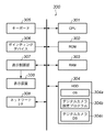
上記を実現するため、先ず、実施形態におけるPC300の処理を図7のフローチャート、並びに、図4乃至図6を用いて説明する。図7のフローチャートは、PC300のHDD304に格納されているデジタルカメラ設定プログラムの処理手順を示している。なお、当然であるが、既にOSが起動しているものとして説明する。
In order to realize the above, first, the processing of the
先ず、管理者がこのプログラムの起動をポインティングデバイス306を用いて起動指示を与えると、ステップS1にて、図4に示す設定ウインドウ400を表示する。
First, when the administrator gives an instruction to start the program using the
図示に示すように、ESS−ID、WEP KEY、Channel、Configの各設定項目毎の入力欄が表示される。設定項目ESS−ID、WEP KEYは文字列を入力することになるのでテキストボックスを表示し、設定項目channel、Configは予め決められた値の中から選択するためコンボボックス形式で表示するようにした。WEP KEYについては、キーボードによるキー入力結果の文字列を内部(RAM303)に保持し、のぞき見を防止するため、キー入力個数は判別できるものの、入力された個々のキーの種別判定ができないように「*」を表示するようにした。 As shown in the drawing, input fields for each setting item of ESS-ID, WEP KEY, Channel, and Config are displayed. Since the setting items ESS-ID and WEP KEY input a character string, a text box is displayed, and the setting items channel and Config are displayed in a combo box format for selecting from predetermined values. . As for WEP KEY, the character string of the key input result by the keyboard is stored in the RAM (RAM 303) to prevent peeping, so that the number of key inputs can be determined but the type of each input key cannot be determined. "*" Is displayed.
管理者は、各設定項目に、キーボード305或いはポインティングデバイス306を用いて設定することになる(ステップS2)。
The administrator sets each setting item using the
各項目への設定が完了したことを示すのは、図示の「次へ」ボタンをクリックすることで行う。このボタンがクリックされたと判断した場合(ステップS3)、処理はステップS4に進むことになる。なお、「キャンセル」ボタンがクリックされた場合には本処理を終了する。 The completion of the setting for each item is performed by clicking the “Next” button shown in the figure. If it is determined that this button has been clicked (step S3), the process proceeds to step S4. If the “Cancel” button is clicked, this process is terminated.
処理がステップS4に進むと、設定ウインドウ400に代えて、図5に示す秘密キー入力ウインドウ500を表示する。ここでは、先ず、コンボボックス500に対してポインティングデバイス306を操作して、設定対象のデジタルカメラの機種を入力(選択)する(ステップS5)。図示では、デジタルカメラの機種名(モデル名)として「DSC−10000 shot」が選択された状態を示している。なお、ここではコンボボックスを例にしているが、キーボードより入力しても構わない。
When the process proceeds to step S4, a secret
このデジタルカメラの機種名の選択が行われると、該当するデジタルカメラの背面画像をHDD304に格納されているデジタルカメラDB304から検索し、それをイメージ表示領域501に表示する。このとき、背面の各種スイッチ(ボタン)の座標位置と、各スイッチに割り当てられたコードも読み込み、その座標位置で示される背面画像の各位置に所定のマークを表示する。
When the model name of the digital camera is selected, a back image of the corresponding digital camera is retrieved from the
なお、デジタルカメラDB304に記憶されている座標位置に該当するスイッチは、シャッターボタン、電源ボタン、並びに、スライド位置を保持するようなスイッチは除外する。シャッターボタンは特別なスイッチとするため(後述)、スライドスイッチはその状態を維持し続けるため、電源ボタンについて説明するまでもないであろう。これ以外のスイッチは、押下した際にONになり、手を放した際にOFFとなるので、通常のキーボードと同様として扱えるので、それを秘密キーの入力を行えるものとして扱う。ただし、ダイヤルが設けられているデジタルカメラの場合には、その回転方向に文字コードを割り当てれば良いであろう。
Note that the switch corresponding to the coordinate position stored in the
さて、管理者は、この背面画像中に表示された所望とする各マーク位置に、ポインティングデバイス306に連動するカーソル(不図示)を移動をクリックすることで、秘密キーを入力していく(ステップS6)。この際、同じスイッチを連続してクリックしても構わないし、その順番、入力回数は問わない。ただし、何回スイッチを操作したかを判別可能とするため、欄502にはスイッチへの入力回数に応じて、所定のマーク(実施形態では「*」)を表示するようにした。
The administrator inputs a secret key by clicking a cursor (not shown) linked to the
こうして、選択されたデジタルカメラの背面画像を用いてのキー入力を終了した場合には、管理者はウインドウの下部の「次へ」ボタンをクリックすることで、秘密キー(内部的にはコード列が保持されている)の入力を確定する(ステップS7がYESとなる)。 In this way, when the key input using the back image of the selected digital camera is finished, the administrator clicks the “Next” button at the bottom of the window, so that the secret key (internally the code string) is displayed. Is held) (step S7 becomes YES).
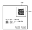
この後、処理はステップS8に進み、図4のウインドウで設定された各パラメータを所定形式のフォーマット(例えば、適当なデリミタで区切る一続きのデータ)にし、図5のウインドウで指定された秘密キーで暗号化を行って、暗号化情報を得る。次いで、ステップS9にて、その暗号化情報から2次元バーコードのイメージデータを作成する。そして、ステップS10に進んで、図6に示す撮影ウインドウ600を表示し、その中の画像表示領域601内に、作成した2次元バーコードを表示させる。そして、設定対象となるデジタルカメラで、この表示ウインドウを撮像(撮影)させる。また、「プリント」ボタンがクリックされた場合(ステップS11)、2次元バーコードを印刷し本処理を終了する。
Thereafter, the process proceeds to step S8, in which each parameter set in the window of FIG. 4 is formatted in a predetermined format (for example, a series of data delimited by an appropriate delimiter), and the secret key specified in the window of FIG. Encrypt to obtain encrypted information. Next, in step S9, two-dimensional barcode image data is created from the encrypted information. Then, the process proceeds to step S10, in which the photographing
以上、実施形態におけるPC300における処理を説明した。次に、実施形態におけるデジタルカメラ100の処理を図8のフローチャートに従って説明する。なお、以下に説明する処理は、デジタルカメラ100が有する表示パネルと各スイッチの操作によるものである。
The processing in the
先ず、ステップS21では、無線LANの設定が指示されたか否かを判定する。無線LANの設定の指示は、メニュー表示し、その中から選択すること行うものとする。無線LANの設定以外の指示であると判定した場合には、ステップS22に進み、対応する処理を行う(例えば通常撮影)。 First, in step S21, it is determined whether or not a wireless LAN setting is instructed. A wireless LAN setting instruction is displayed on a menu and selected from the menu. If it is determined that the instruction is other than setting of the wireless LAN, the process proceeds to step S22, and corresponding processing is performed (for example, normal shooting).
また、無線LANの設定が指示された場合には、ステップS23に進み、2次元バーコードの撮影を促すメッセージを表示パネルに表示し、ステップS24でシャッターボタン710の押下を待つ。この際に撮影するのは、PCの画面もしくは印刷物となる。ただし、撮影の際には、ストロボはOFFにし、シャッタースピードは垂直同期信号(通常のCRTでは60乃至80Hz)よりも遅くする。画面の反射光の影響を無くし、且つ、表示画面全体の像が撮影できるようにするためである。また、表示画面を撮像する場合に備えて、コントラストを高くして表示する。
If the setting of the wireless LAN is instructed, the process proceeds to step S23, a message for prompting the photographing of the two-dimensional barcode is displayed on the display panel, and the press of the
シャッターボタンが押下されると撮像を行い、ステップS25で2次バーコードのデコードを行う。そして、ステップS26にて、撮像画像中に2次元バーコードが存在しない等の理由でデコード処理が失敗したと判断した場合には、ステップS23以降を繰り返す。 When the shutter button is pressed, imaging is performed, and the secondary barcode is decoded in step S25. If it is determined in step S26 that the decoding process has failed due to the absence of a two-dimensional barcode in the captured image, step S23 and subsequent steps are repeated.
2次バーコードのデコードが成功した場合、処理はステップS27に進み、秘密キーの入力を促すメッセージを表示する。そして、秘密キー入力対象となり得る全スイッチを、本来の機能を無効にし、単にそのスイッチのONになったか否かの判定処理であるステップS28に進む。 If the decoding of the secondary barcode is successful, the process proceeds to step S27, and a message prompting the input of the secret key is displayed. Then, the original function of all the switches that can be the secret key input target is invalidated, and the process proceeds to step S28, which is a process for determining whether or not the switch is simply turned on.
このステップS28では、スイッチがONになる度に、該当するコードを生成し、蓄積する処理を行う。そして、ステップS29にで、シャッターボタンが押下されたと判断しない限り、入力を継続する。 In this step S28, every time the switch is turned on, a corresponding code is generated and stored. Then, in step S29, the input is continued unless it is determined that the shutter button has been pressed.
シャッターボタンが押下されたと判断した場合(ここでは撮影はしない)、入力し蓄積されたコード列に従って、2次元バーコードのデコード結果の情報の暗号復号処理を行う(ステップS30)。この暗号復号処理で得られた情報が所定形式のデータフォーマットになっているか否かを判別することで、暗号復号が成功したか否かを判断する(ステップS31)。暗号復号が不成功であると判断した場合にはステップS12でエラー表示し、本処理を終える。また、暗号復号が成功した場合には、得られたパラメータに従って通信部110の無線LANに関する設定を行い、その設定内容を記憶保持するため不揮発性メモリ56に登録する(次回、起動した際には、この登録内容で無線LANの構成を初期化する)。
If it is determined that the shutter button has been pressed (not photographed here), the decryption process is performed on the information of the decoding result of the two-dimensional barcode according to the input and stored code string (step S30). It is determined whether or not the encryption / decryption is successful by determining whether or not the information obtained by the encryption / decryption processing is in a predetermined data format (step S31). If it is determined that the decryption is unsuccessful, an error is displayed in step S12, and the process is terminated. If the encryption / decryption is successful, the wireless LAN of the
以上説明したように本実施形態によれば、PC上で作成した設定パラメータを暗号化し、その結果を2次元バーコード形式にして表示もしくはプリント出力することにより、設定パラメータが漏洩することを防ぐことが可能となる。また、デジタルカメラ側の操作は、通常の文字の入力操作と異なり、操作部に設けられたスイッチやボタンの押下順序に注意して入力操作を行え、設定が完了するので、操作が簡便なり、且つ、設定パラメータに対する技術的知識がなくても無線LANの設定が行えるようになる。 As described above, according to the present embodiment, the setting parameter created on the PC is encrypted, and the result is displayed or printed out in the two-dimensional barcode format, thereby preventing the setting parameter from leaking. Is possible. In addition, unlike the normal character input operation, the digital camera side can be operated with attention to the order of pressing the switches and buttons provided on the operation unit, and the setting is completed, making the operation simple, In addition, the wireless LAN can be set without technical knowledge of the setting parameters.
また、実施形態によると、暗号化の秘密キーの入力は、設定対象である実際のデジタルカメラの画像(実施形態では背面のみとしたが、上部に設けられたスイッチを利用するために斜視図の画像でも良い)を利用して行えるので、暗号復号する際の秘密キーの操作に支障を来すこともない。 In addition, according to the embodiment, the input of the encryption private key is an image of an actual digital camera to be set (in the embodiment, only the back surface is used, but in order to use the switch provided in the upper part, This can be done using an image), so that it does not hinder the operation of the secret key when performing decryption.
なお、実施形態では、2次元バーコードによる設定を例にして説明したが、無線LANに対する技術知識が十分にある利用者用に、通常の文字入力か2次元バーコードの撮影かを選択させるようにしても良い。 In the embodiment, the setting by the two-dimensional barcode has been described as an example. However, for a user who has sufficient technical knowledge about the wireless LAN, the user can select normal character input or two-dimensional barcode shooting. Anyway.
また、デジタルカメラDB304cに格納されているデジタルカメラの機種別のスイッチの位置とコードの関係において、「コード」はデジタルカメラの機種毎に重複することがないようにすることが望ましい。理由は、同一メーカの場合である場合、異なる機種でも背面の操作スイッチの並びは同じか、似通ったものとなる傾向があるからである。すなわち、選択したデジタルカメラと同一機種以外では暗号復号を成功させないようにことができる。
Further, in the relationship between the switch position and code of each model of the digital camera stored in the
また、図4で設定したパラメータをファイルとして保存し、次回、それを利用するようにしても良い。このようにすると、別機種の2次元バーコードを作成する際に、そのファイルを読み込み、後はその別機種名を設定し秘密キーを入力すれば良いので、管理者の操作を簡便なものとすることができる。 Also, the parameters set in FIG. 4 may be saved as a file and used next time. In this way, when creating a two-dimensional barcode for another model, the file can be read, then the name of the other model can be set and the secret key can be entered. can do.
また、実施形態では、デジタルカメラの無線LANの設定ついて説明したが、設定する対象は無線LANに限らないし、対象装置は撮像手段を備える或いは撮像手段を接続可能な装置であれば良いので、デジタルカメラに限定されるものではない。要するに、情報漏洩を防ぐ必要のある情報を、該当する装置で撮像し、設定する場合に適用可能である。 In the embodiment, the setting of the wireless LAN of the digital camera has been described. However, the target to be set is not limited to the wireless LAN, and the target device may be any device that includes an imaging unit or can be connected to an imaging unit. It is not limited to cameras. In short, the present invention is applicable when information that needs to be prevented from being leaked is imaged and set by a corresponding device.
さらにまた、実施形態で説明したように、本実施形態の主要な処理はPC300にインストールされたプログラムにあるので、当然、このようなプログラムも本願発明の範疇にある。そして、通常、コンピュータプログラムはCD−ROM等のコンピュータ可読記憶媒体をコンピュータにセットし、システムにコピーもしくはインストールすることで実行可能になるわけであるから、当然、このようなコンピュータ可読記憶媒体も本発明の範疇に含まれる。
Furthermore, as described in the embodiment, since the main processing of the present embodiment is in a program installed in the
Claims (12)
前記電子機器用のパラメータを入力する入力手段と、
設定対象と成り得る電子機器が有する操作スイッチに対応する画像と、前記操作スイッチに対応するコード情報を記憶する電子機器情報記憶手段と、
設定対象となる電子機器を選択する選択手段と、
選択された電子機器に対応する前記画像とコード情報とを、前記電子機器情報記憶手段から取得する取得手段と、
前記取得手段で取得された画像を表示し、表示された画像中の操作スイッチに対応するコード情報を用いてコードを生成するコード生成手段と、
該入力手段で入力されたパラメータを、前記コード生成手段で生成されたコードを用いて暗号化し、暗号化情報を生成する暗号化手段と、
該暗号化手段で得られた暗号化情報に基づき、前記電子機器の前記撮像手段で撮像するための可視画像を生成し、出力する画像出力手段と
を備えることを特徴とする情報処理装置。 An information processing apparatus for creating the parameter for an electronic device including an imaging unit and a processing unit that processes according to the parameter,
Input means for inputting parameters for the electronic device;
An electronic device information storage means for storing an image corresponding to an operation switch included in an electronic device that can be set, and code information corresponding to the operation switch;
A selection means for selecting an electronic device to be set;
Obtaining means for obtaining the image and code information corresponding to the selected electronic device from the electronic device information storage means;
Code generating means for displaying an image acquired by the acquiring means and generating code using code information corresponding to an operation switch in the displayed image;
An encryption unit that encrypts the parameter input by the input unit using the code generated by the code generation unit and generates encryption information;
An information output apparatus comprising: an image output unit that generates and outputs a visible image to be captured by the imaging unit of the electronic device based on the encryption information obtained by the encryption unit.
前記取得手段は、前記電子機器情報記憶手段から前記位置情報も取得し、
前記コード生成手段は、表示された画像中の指示位置から、いずれの操作スイッチが指示されたかを判定し、指示された操作スイッチに対応するコード情報から、暗号化のためのコードを生成することを特徴とする請求項1に記載の情報処理装置。 Further, the electronic device information storage means stores position information of operation switches of the electronic device,
The acquisition means also acquires the position information from the electronic device information storage means,
The code generation means determines which operation switch is instructed from an indicated position in the displayed image, and generates a code for encryption from code information corresponding to the instructed operation switch. The information processing apparatus according to claim 1.
入力手段が、前記電子機器用のパラメータを入力する入力工程と、
選択手段が、設定対象となる電子機器を選択する選択工程と、
取得手段が、選択された電子機器に対応する前記画像とコード情報とを、前記電子機器情報記憶手段から取得する取得工程と、
コード生成手段が、前記取得手段で取得された画像を表示し、表示された画像中の操作スイッチに対応するコード情報を用いてコードを生成するコード生成工程と、
暗号化手段が、該入力手段で入力されたパラメータを、前記コード生成工程で生成されたコードを用いて暗号化し、暗号化情報を生成する暗号化工程と、
画像出力手段が、前記暗号化工程で得られた暗号化情報に基づき、前記電子機器の前記撮像手段で撮像するための可視画像を生成し、出力する画像出力工程と
を備えることを特徴とする情報処理装置の制御方法。 An electronic device that includes an electronic device information storage unit that stores an image corresponding to an operation switch included in an electronic device that can be a setting target, and code information corresponding to the operation switch, includes an imaging unit, and a processing unit that performs processing according to a parameter. A method of controlling an information processing apparatus that creates the parameter for equipment,
An input step for inputting parameters for the electronic device;
A selection step in which the selection means selects an electronic device to be set; and
An acquisition step in which the acquisition unit acquires the image and code information corresponding to the selected electronic device from the electronic device information storage unit;
A code generation step, wherein the code generation means displays the image acquired by the acquisition means, and generates a code using code information corresponding to the operation switch in the displayed image;
An encryption unit encrypts the parameter input by the input unit using the code generated in the code generation step, and generates encryption information; and
The image output means includes an image output process for generating and outputting a visible image to be captured by the imaging means of the electronic device based on the encryption information obtained in the encryption process. A method for controlling an information processing apparatus.
前記電子機器用のパラメータを入力する入力手段と、
設定対象となる電子機器を選択する選択手段と、
選択された電子機器に対応する前記画像とコード情報とを、前記電子機器情報記憶手段から取得する取得手段と、
前記取得手段で取得された画像を表示し、表示された画像中の操作スイッチに対応するコード情報を用いてコードを生成するコード生成手段と、
該入力手段で入力されたパラメータを、前記コード生成手段で生成されたコードを用いて暗号化し、暗号化情報を生成する暗号化手段と、
該暗号化手段で得られた暗号化情報に基づき、前記電子機器の前記撮像手段で撮像するための可視画像を生成し、出力する画像出力手段と
として機能させることを特徴とするコンピュータプログラム。 A computer having an electronic device information storage unit that stores an image corresponding to an operation switch of an electronic device that can be a setting target and code information corresponding to the operation switch is read and executed, whereby processing is performed according to an imaging unit and parameters. A computer program that functions as an information processing device for creating the parameter for an electronic device comprising processing means for
Input means for inputting parameters for the electronic device;
A selection means for selecting an electronic device to be set;
Obtaining means for obtaining the image and code information corresponding to the selected electronic device from the electronic device information storage means;
Code generating means for displaying an image acquired by the acquiring means and generating code using code information corresponding to an operation switch in the displayed image;
An encryption unit that encrypts the parameter input by the input unit using the code generated by the code generation unit and generates encryption information;
A computer program that functions as image output means for generating and outputting a visible image to be picked up by the image pickup means of the electronic device based on encryption information obtained by the encryption means.
前記パラメータの設定を指示する指示手段と、
該指示手段で指示された場合、前記撮像部によって、暗号化情報が含まれた画像を撮像し、撮像画像を取得する画像取得手段と、
取得した画像をデコードして、前記暗号化情報を生成する生成手段と、
生成された暗号化情報を、前記操作部による操作順に従って生成された情報をキーにして暗号復号する暗号復号手段と、
該暗号復号手段によって復号されたデータを前記パラメータとして設定する設定手段と
を備えることを特徴とする電子機器。 An electronic device that has an imaging unit and an operation unit and performs processing according to set parameters,
Instruction means for instructing the setting of the parameters;
When instructed by the instruction unit, the image capturing unit captures an image including encryption information and acquires a captured image by the imaging unit;
Generating means for decoding the acquired image and generating the encrypted information;
Encryption / decryption means for encrypting / decrypting the generated encrypted information using the information generated according to the operation order by the operation unit as a key;
An electronic device comprising: setting means for setting data decrypted by the encryption / decryption means as the parameter.
前記パラメータは前記無線LAN通信手段の通信パラメータであることを特徴とする請求項9に記載の電子機器。 Furthermore, it has a wireless LAN communication means,
The electronic device according to claim 9, wherein the parameter is a communication parameter of the wireless LAN communication unit.
指示手段が、前記パラメータの設定を指示する指示工程と、
画像取得手段が、該指示工程で指示された場合、前記撮像部によって、暗号化情報が含まれた画像を撮像し、撮像画像を取得する画像取得工程と、
生成手段が、取得した画像をデコードして、前記暗号化情報を生成する生成工程と、
暗号復号手段が、生成された暗号化情報を、前記操作部による操作順に従って生成された情報をキーにして暗号復号する暗号復号工程と、
設定手段が、該暗号復号工程によって復号されたデータを前記パラメータとして設定する設定工程と
を備えることを特徴とする電子機器の制御方法。 A method for controlling an electronic device that has an imaging unit and an operation unit and performs processing according to set parameters,
An instruction means for instructing the setting of the parameter;
When the image acquisition unit is instructed in the instruction step, the image acquisition unit captures an image including encryption information by the imaging unit, and acquires a captured image;
A generating step for generating the encrypted information by decoding the acquired image; and
An encryption / decryption step, wherein the encryption / decryption means decrypts the generated encrypted information using the information generated according to the operation order by the operation unit as a key;
A setting means comprising: a setting step of setting the data decrypted by the encryption / decryption step as the parameter.
前記パラメータは前記無線LAN通信手段の通信パラメータであることを特徴とする請求項11に記載の電子機器の制御方法。 The electronic device has a wireless LAN communication means,
12. The method of controlling an electronic device according to claim 11, wherein the parameter is a communication parameter of the wireless LAN communication unit.
Priority Applications (3)
| Application Number | Priority Date | Filing Date | Title |
|---|---|---|---|
| JP2004304344A JP4101225B2 (en) | 2004-10-19 | 2004-10-19 | Electronic apparatus, information processing apparatus, control method therefor, computer program, and computer-readable storage medium |
| US11/253,098 US7499567B2 (en) | 2004-10-19 | 2005-10-18 | Electronic device and information processing apparatus and control method thereof, and computer program and computer-readable storage medium |
| CNB2005101094168A CN100393107C (en) | 2004-10-19 | 2005-10-18 | Electronic device and information processing apparatus and control method thereof, |
Applications Claiming Priority (1)
| Application Number | Priority Date | Filing Date | Title |
|---|---|---|---|
| JP2004304344A JP4101225B2 (en) | 2004-10-19 | 2004-10-19 | Electronic apparatus, information processing apparatus, control method therefor, computer program, and computer-readable storage medium |
Publications (3)
| Publication Number | Publication Date |
|---|---|
| JP2006121185A JP2006121185A (en) | 2006-05-11 |
| JP2006121185A5 JP2006121185A5 (en) | 2006-12-21 |
| JP4101225B2 true JP4101225B2 (en) | 2008-06-18 |
Family
ID=36180791
Family Applications (1)
| Application Number | Title | Priority Date | Filing Date |
|---|---|---|---|
| JP2004304344A Expired - Fee Related JP4101225B2 (en) | 2004-10-19 | 2004-10-19 | Electronic apparatus, information processing apparatus, control method therefor, computer program, and computer-readable storage medium |
Country Status (3)
| Country | Link |
|---|---|
| US (1) | US7499567B2 (en) |
| JP (1) | JP4101225B2 (en) |
| CN (1) | CN100393107C (en) |
Families Citing this family (38)
| Publication number | Priority date | Publication date | Assignee | Title |
|---|---|---|---|---|
| JP2007274567A (en) * | 2006-03-31 | 2007-10-18 | Olympus Imaging Corp | Information apparatus system and electronic camera used for information apparatus system |
| JP2007312179A (en) | 2006-05-19 | 2007-11-29 | Seiko Epson Corp | Image display system, image display device of the image display system, portable terminal and connection establishment method in image display system |
| JP2008113410A (en) * | 2006-10-02 | 2008-05-15 | Canon Inc | Image processing apparatus and control method thereof, and reading method in image reading system |
| KR100842570B1 (en) * | 2006-11-03 | 2008-07-01 | 삼성전자주식회사 | Method and apparatus for displaying a plurality of images in a mobile station |
| US8131019B2 (en) * | 2007-10-10 | 2012-03-06 | Pitney Bowes Inc. | Method and system for capturing images moving at high speed |
| KR101526012B1 (en) * | 2008-10-30 | 2015-06-05 | 삼성전자주식회사 | Method and apparatus for data communication using digital image processing |
| JP2010114584A (en) * | 2008-11-05 | 2010-05-20 | Mitsubishi Electric Corp | Camera device |
| US8851380B2 (en) | 2009-01-27 | 2014-10-07 | Apple Inc. | Device identification and monitoring system and method |
| US8645383B2 (en) | 2009-01-27 | 2014-02-04 | Stephen J. Brown | Content management system using sources of experience data and modules for quantification and visualization |
| US8930490B2 (en) | 2009-01-27 | 2015-01-06 | Apple Inc. | Lifestream annotation method and system |
| US8096477B2 (en) * | 2009-01-27 | 2012-01-17 | Catch, Inc. | Semantic note taking system |
| US9183291B2 (en) | 2009-01-27 | 2015-11-10 | Apple Inc. | Mobile content capture and discovery system based on augmented user identity |
| US20120122397A1 (en) | 2009-01-27 | 2012-05-17 | Brown Stephen J | Semantic Note Taking System |
| US20120111936A1 (en) | 2009-01-27 | 2012-05-10 | Brown Stephen J | Semantic Note Taking System |
| US8290287B2 (en) * | 2009-03-09 | 2012-10-16 | Laurence Hamid | Method for displaying encoded image data |
| US8281343B2 (en) * | 2009-05-19 | 2012-10-02 | Cisco Technology, Inc. | Management and display of video content |
| JP5375346B2 (en) * | 2009-06-08 | 2013-12-25 | カシオ計算機株式会社 | Communication system and communication method |
| CN102088700A (en) * | 2009-12-03 | 2011-06-08 | 宏碁股份有限公司 | Electronic device capable of automatically establishing communication connection and method for establishing communication connection |
| US8319852B2 (en) * | 2010-02-04 | 2012-11-27 | Research In Motion Limited | Method, system and apparatus for managing notification profiles using graphical indicators |
| JP5226038B2 (en) * | 2010-06-11 | 2013-07-03 | 任天堂株式会社 | GAME PROGRAM, GAME DEVICE, AND GAME CONTROL METHOD |
| CN101980501A (en) * | 2010-09-30 | 2011-02-23 | 福建新大陆电脑股份有限公司 | Mobile communication terminal and network connection method thereof |
| KR101836876B1 (en) * | 2011-03-02 | 2018-03-09 | 삼성전자주식회사 | Apparatus and method for performing network connection in portable terminal |
| TWI576721B (en) * | 2011-07-25 | 2017-04-01 | 宏正自動科技股份有限公司 | Digital signage apparatus, portable device synchronization system, and method thereof |
| JP2013143616A (en) | 2012-01-10 | 2013-07-22 | Nec Access Technica Ltd | Radio communication terminal, information provision medium, access point, radio communication method, and program |
| US20130282590A1 (en) * | 2012-04-19 | 2013-10-24 | Ebay, Inc. | Electronic payments using visual code |
| CN103390148B (en) * | 2012-05-10 | 2017-04-26 | 宏碁股份有限公司 | Connection setting method and system using barcode patterns and user devices of barcode patterns |
| JP5675747B2 (en) | 2012-10-18 | 2015-02-25 | オリンパス株式会社 | Wireless communication system, portable terminal, digital camera, communication method and program |
| KR20140086415A (en) * | 2012-12-28 | 2014-07-08 | 삼성전기주식회사 | Device of data communication using video and method of data communication using video |
| US9565173B2 (en) * | 2013-03-26 | 2017-02-07 | Xerox Corporation | Systems and methods for establishing trusted, secure communications from a mobile device to a multi-function device |
| CN103428438A (en) * | 2013-08-05 | 2013-12-04 | 移康智能科技(上海)有限公司 | IP (internet protocol) camera and network parameter setting method thereof |
| JP6164079B2 (en) * | 2013-12-24 | 2017-07-19 | 株式会社デンソーウェーブ | Information terminal and information terminal system |
| WO2015102564A1 (en) | 2013-12-30 | 2015-07-09 | Empire Technology Developement LLC | Information rendering scheme |
| NZ746653A (en) * | 2015-03-03 | 2020-02-28 | Wonderhealth Llc | Access control for encrypted data in machine-readable identifiers |
| US20160307186A1 (en) * | 2015-04-20 | 2016-10-20 | Mastercard International Incorporated | Verification of contactless payment card for provisioning of payment credentials to mobile device |
| EP3323031B1 (en) * | 2015-07-13 | 2021-05-12 | Vertiv Corporation | Method and apparatus to retrieve data from power distribution units |
| JP6793714B2 (en) * | 2015-07-13 | 2020-12-02 | バーティブ・コーポレーション | Methods and equipment for retrieving data from the power distribution unit |
| US11133703B2 (en) | 2015-07-13 | 2021-09-28 | Vertiv Corporation | Method and apparatus to retrieve data from power distribution units |
| US10158612B2 (en) | 2017-02-07 | 2018-12-18 | Hand Held Products, Inc. | Imaging-based automatic data extraction with security scheme |
Family Cites Families (13)
| Publication number | Priority date | Publication date | Assignee | Title |
|---|---|---|---|---|
| US5583933A (en) * | 1994-08-05 | 1996-12-10 | Mark; Andrew R. | Method and apparatus for the secure communication of data |
| JP3431331B2 (en) * | 1995-03-01 | 2003-07-28 | 株式会社日立製作所 | Video encoding device, video transmission device, and video conference device |
| JPH094591A (en) | 1995-06-19 | 1997-01-07 | Ebara Corp | Method and device for controlling positive displacement fluid machine |
| US5724428A (en) * | 1995-11-01 | 1998-03-03 | Rsa Data Security, Inc. | Block encryption algorithm with data-dependent rotations |
| FR2753859B1 (en) * | 1996-09-25 | 2001-09-28 | Fintel Sa | METHOD AND SYSTEM FOR SECURING THE SERVICES OF TELECOMMUNICATION OPERATORS |
| US6304857B1 (en) * | 1998-06-08 | 2001-10-16 | Microsoft Corporation | Distributed electronic billing system with gateway interfacing biller and service center |
| US6304657B1 (en) | 1999-05-26 | 2001-10-16 | Matsushita Electric Industrial Co., Ltd. | Data encryption apparatus using odd number of shift-rotations and method |
| US7000107B2 (en) * | 2000-09-30 | 2006-02-14 | Microsoft Corporation | System and method for using dynamic web components to remotely control the security state of web pages |
| JP2003085474A (en) * | 2001-09-06 | 2003-03-20 | Denso Corp | Optical information reader and information code output device |
| JP3905773B2 (en) * | 2002-02-26 | 2007-04-18 | 株式会社リコー | Document information processing method, document information processing apparatus, document information processing system, and program |
| US7367514B2 (en) * | 2003-07-03 | 2008-05-06 | Hand Held Products, Inc. | Reprogramming system including reprogramming symbol |
| JP2005210267A (en) * | 2004-01-21 | 2005-08-04 | Canon I-Tech Inc | Print system and setting method of image input unit |
| JP2006001063A (en) * | 2004-06-16 | 2006-01-05 | Fuji Photo Film Co Ltd | Direct print system |
-
2004
- 2004-10-19 JP JP2004304344A patent/JP4101225B2/en not_active Expired - Fee Related
-
2005
- 2005-10-18 US US11/253,098 patent/US7499567B2/en not_active Expired - Fee Related
- 2005-10-18 CN CNB2005101094168A patent/CN100393107C/en not_active Expired - Fee Related
Also Published As
| Publication number | Publication date |
|---|---|
| JP2006121185A (en) | 2006-05-11 |
| US7499567B2 (en) | 2009-03-03 |
| CN1764241A (en) | 2006-04-26 |
| CN100393107C (en) | 2008-06-04 |
| US20060083404A1 (en) | 2006-04-20 |
Similar Documents
| Publication | Publication Date | Title |
|---|---|---|
| JP4101225B2 (en) | Electronic apparatus, information processing apparatus, control method therefor, computer program, and computer-readable storage medium | |
| JP5110805B2 (en) | Communication terminal, communication method and program capable of wired and wireless communication | |
| US8023031B2 (en) | Image pickup apparatus with display apparatus, and display control method for display apparatus | |
| KR101435963B1 (en) | Configuring apparatus, image output apparatus, and methods of controlling the same | |
| US9094610B2 (en) | Image capturing apparatus and image capturing apparatus control method | |
| JP4367955B2 (en) | Imaging apparatus and control method thereof | |
| JP4891270B2 (en) | Image editing apparatus, image editing method and program | |
| JP2007243923A (en) | Image processing apparatus, control method thereof, and program | |
| JP2010009521A (en) | Image providing apparatus, image output apparatus, and image output system | |
| JP4759372B2 (en) | Communication terminal for informing wireless communication state and control method thereof | |
| JP2007081741A (en) | Imaging apparatus and its control method | |
| JP2005221771A (en) | Imaging device and function display method | |
| JP4881195B2 (en) | IMAGING DEVICE, ITS CONTROL METHOD, PROGRAM, AND STORAGE MEDIUM | |
| JP4799207B2 (en) | COMMUNICATION DEVICE, ITS CONTROL METHOD, PROGRAM | |
| JP5019566B2 (en) | Imaging apparatus, control method therefor, computer program, and storage medium | |
| JP2008072524A (en) | Information processor, control method, program, and storage medium | |
| JP5142496B2 (en) | Information processing apparatus, information processing apparatus control method, program, and storage medium | |
| JP2006039203A (en) | Imaging apparatus, and its control method | |
| JP2007221686A (en) | Radio communication enabled imaging apparatus, control method thereof, and program | |
| JP5555103B2 (en) | Image recording apparatus, method and program | |
| JP2005117242A (en) | Imaging apparatus and control method therefor | |
| JP4865202B2 (en) | File transfer apparatus, program, and computer-readable recording medium | |
| JP2011066806A (en) | Image processor | |
| JP2005223616A (en) | Image pickup apparatus | |
| JP2008060844A (en) | Image processor and image processing method |
Legal Events
| Date | Code | Title | Description |
|---|---|---|---|
| A521 | Request for written amendment filed |
Free format text: JAPANESE INTERMEDIATE CODE: A523 Effective date: 20061107 |
|
| A977 | Report on retrieval |
Free format text: JAPANESE INTERMEDIATE CODE: A971007 Effective date: 20070612 |
|
| A131 | Notification of reasons for refusal |
Free format text: JAPANESE INTERMEDIATE CODE: A131 Effective date: 20070618 |
|
| A521 | Request for written amendment filed |
Free format text: JAPANESE INTERMEDIATE CODE: A523 Effective date: 20070808 |
|
| TRDD | Decision of grant or rejection written | ||
| A01 | Written decision to grant a patent or to grant a registration (utility model) |
Free format text: JAPANESE INTERMEDIATE CODE: A01 Effective date: 20080314 |
|
| A61 | First payment of annual fees (during grant procedure) |
Free format text: JAPANESE INTERMEDIATE CODE: A61 Effective date: 20080318 |
|
| FPAY | Renewal fee payment (event date is renewal date of database) |
Free format text: PAYMENT UNTIL: 20110328 Year of fee payment: 3 |
|
| R150 | Certificate of patent or registration of utility model |
Free format text: JAPANESE INTERMEDIATE CODE: R150 |
|
| FPAY | Renewal fee payment (event date is renewal date of database) |
Free format text: PAYMENT UNTIL: 20120328 Year of fee payment: 4 |
|
| FPAY | Renewal fee payment (event date is renewal date of database) |
Free format text: PAYMENT UNTIL: 20130328 Year of fee payment: 5 |
|
| FPAY | Renewal fee payment (event date is renewal date of database) |
Free format text: PAYMENT UNTIL: 20140328 Year of fee payment: 6 |
|
| LAPS | Cancellation because of no payment of annual fees |