JP4100889B2 - Short voltage regulator - Google Patents
Short voltage regulator Download PDFInfo
- Publication number
- JP4100889B2 JP4100889B2 JP2001273527A JP2001273527A JP4100889B2 JP 4100889 B2 JP4100889 B2 JP 4100889B2 JP 2001273527 A JP2001273527 A JP 2001273527A JP 2001273527 A JP2001273527 A JP 2001273527A JP 4100889 B2 JP4100889 B2 JP 4100889B2
- Authority
- JP
- Japan
- Prior art keywords
- thyristor
- voltage regulator
- chip
- short
- heat sink
- Prior art date
- Legal status (The legal status is an assumption and is not a legal conclusion. Google has not performed a legal analysis and makes no representation as to the accuracy of the status listed.)
- Expired - Lifetime
Links
Images


Landscapes
- Thyristors (AREA)
Description
【0001】
【産業上の利用分野】
従来電圧調整装置には、ショート式、オープン式、フィールド式などの種類がある。
この中でも、ショート式は発電機との組み合わせのシステムが安価というメリットがあり、二輪車に数多く採用されている。本発明はショート式電圧調整装置内のサイリスタの搭載方法に関するものである。
【0002】
【従来の技術】
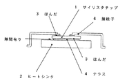
従来のショート式電圧調整装置は、サイリスタチップの発熱が大きいため、ヒートシンクにベアチップを直接搭載して、その熱を外部に逃していた。ところが、通常サイリスタチップはアノード面に逆耐圧を確保するために、ガラスがつけられている。これをフラットなヒートシンクにそのまま搭載すると、ガラスがあるため、チップがガラスの厚み分浮いてしまう。この浮きは、熱伝導の妨げ、耐久劣化に影響のある気泡(ボイド)の抱き込みなどの悪影響を及ぼす。そこで、通常は、ヒートシンク上に、テラス(段差加工)を設け、テラスの上にサイリスタチップを搭載し、ガラスがテラスにかからないようにしていた。
【0003】
しかし、この場合ガラスがテラスにかからないようにしてチップを搭載するのは、やっかいであるし、また、テラスつきの高価なヒートシンクを使用しなければならない。また、テラスはチップズレ落ちの原因となり、ズレ落ちはチップの傾き、熱伝導不良の原因となる。また、通常、ショート式電圧調整装置は二輪車などに搭載される部品であるため、ヒートシンク、サイリスタチップ、接続子をはんだ接続した後、樹脂封止するが、テラスのあるものを使用していた場合は、そのチップとヒートシンクの隙間に樹脂が入り込むことがあった。樹脂は熱膨張率が他のものと違うため、長い間使用しているうちに、はんだ劣化を促進するという問題があった。
【0004】
【発明が解決する課題】
本発明は、サイリスタチップをフラットなヒートシンクに直接搭載することにより、製造を容易にし、信頼性を向上し、特性を向上させたショート式電圧調整装置を供給するものである。
【0005】
【課題を解決するための手段】
本発明は、発電機により発生した余分なエネルギーを、ダイオードとサイリスタにより熱として消費するショート式電圧調整装置において、サイリスタは、アノード側に耐圧確保のためのガラスのないサイリスタを用い、かつアノード面を下にしてチップをヒートシンクのフラットな面に直接搭載した。
【0006】
【作用】
通常のサイリスタは、素子単体として使用する場合、逆方向耐圧が必要なので耐圧確保のためアノード面にガラスが必要となる。しかし、ショート式電圧調整装置には必ず サイリスタと逆向きのダイオードが並列に入っている。よって、サイリスタには逆耐圧は必要ない。
【0007】
【発明の実施の形態】
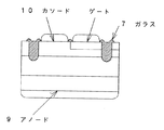
図1は本発明のショート式電圧調整装置の一実施例側面図であり、これを製造するには、テラスのないヒートシンクにはんだを乗せ、その上に下面にガラスのないサイリスタチップを搭載し、ソルダー等でその他の部品とともにはんだ固定する。それを一つの部品とし、制御回路とともにケースに入れ、モールド樹脂にて全ての部品を固定し、電圧調整器を完成させる。
【0008】
図5は単相式のショート式電圧調整装置の電流整流回路一例であり、バッテリーが充電を必要としているときは、発電機により発生した電流は8ダイオード(+側)を通り、+に充電される。バッテリーが満充電のときは発電機により発生した電流は、11サイリスタがオンしている状態にあるので、発電機により発生した電流は11サイリスタから12ダイオード(−側)を通り、発電機に戻る。
本実施例は、単相式の例を記載したが、三相式でも利用できることは言うまでもない。
【0009】
【発明の効果】
本発明は産業上利用可能性大なるものであり下記のような効果がある。
▲1▼サイリスタチップの製造コストが安い
▲2▼フラットで安いヒートシンクが使える
▲3▼サイリスタチップの搭載が容易
▲4▼サイリスタチップの接続強度が増加する
▲5▼サイリスタチップ熱伝導効率も20%程度上昇
▲6▼チップとヒートシンクの間に樹脂の入り込みが無くなり信頼性向上する
【図面の簡単な説明】
【図1】本発明の一実施例側面図
【図2】本発明のサイリスタチップ側面図
【図3】従来の一実施例側面図
【図4】従来のサイリスタチップ側面図
【図5】ショート式電圧調整装置回路部分図
【符号の説明】
1 サイリスタチップ
2 ヒートシンク
3 はんだ
4 テラス
5 隙間
6 接続子
7 ガラス
8 ダイオード(+側)
9 アノード
10 カソード
11 サイリスタ
12 ダイオード (−側)[0001]
[Industrial application fields]
Conventional voltage regulators include a short type, an open type, and a field type.
Among these, the short type has the merit that the system combined with the generator is inexpensive, and is used in many motorcycles. The present invention relates to a method for mounting a thyristor in a short voltage regulator.
[0002]
[Prior art]
In the conventional short-type voltage regulator, since the heat generated by the thyristor chip is large, the bare chip is directly mounted on the heat sink and the heat is released to the outside. However, the thyristor chip is usually provided with glass in order to ensure a reverse breakdown voltage on the anode surface. If this is mounted on a flat heat sink as it is, there will be glass, and the chip will float by the thickness of the glass. This floating has an adverse effect such as the inclusion of bubbles that impede heat conduction and affect durability deterioration. Therefore, usually, a terrace (step processing) is provided on the heat sink, and a thyristor chip is mounted on the terrace so that the glass does not cover the terrace.
[0003]
In this case, however, it is troublesome to mount the chip so that the glass does not cover the terrace, and an expensive heat sink with a terrace must be used. Further, the terrace causes chip misalignment, and the misalignment causes chip tilt and poor heat conduction. Also, since the short-type voltage regulator is usually a component mounted on a motorcycle, etc., after soldering the heat sink, thyristor chip, and connector, it is resin-sealed, but the one with a terrace is used In some cases, the resin entered the gap between the chip and the heat sink. Since the thermal expansion coefficient of the resin is different from that of other resins, there has been a problem that the deterioration of the solder is promoted while being used for a long time.
[0004]
[Problems to be solved by the invention]
The present invention provides a short-type voltage regulator that facilitates manufacture, improves reliability, and improves characteristics by directly mounting a thyristor chip on a flat heat sink.
[0005]
[Means for Solving the Problems]
The present invention relates to a short-type voltage regulator that consumes excess energy generated by a generator as heat by a diode and a thyristor. The thyristor uses a glass-free thyristor on the anode side to secure a withstand voltage, and the anode surface The chip was mounted directly on the flat surface of the heat sink with the face down.
[0006]
[Action]
When a normal thyristor is used as a single element, a reverse breakdown voltage is required, so glass is required on the anode surface to ensure a breakdown voltage. However, a short-type voltage regulator always has a thyristor and a reverse diode in parallel. Therefore, the reverse breakdown voltage is not necessary for the thyristor.
[0007]
DETAILED DESCRIPTION OF THE INVENTION
FIG. 1 is a side view of an embodiment of a short-type voltage regulator according to the present invention. In order to manufacture this, a solder is placed on a heat sink without a terrace, and a thyristor chip without glass is mounted on the lower surface. Solder together with other parts with solder. Make it a single component, put it in the case together with the control circuit, fix all the components with mold resin, and complete the voltage regulator.
[0008]
Fig. 5 shows an example of a current rectifier circuit of a single-phase short-type voltage regulator. When the battery needs charging, the current generated by the generator passes through 8 diodes (+ side) and is charged to +. The When the battery is fully charged, the current generated by the generator is in a state in which the 11 thyristor is on, so that the current generated by the generator returns from the 11 thyristor through the 12 diode (− side) to the generator. .
In this embodiment, an example of a single-phase type is described, but it is needless to say that a three-phase type can also be used.
[0009]
【The invention's effect】
The present invention has great industrial applicability and has the following effects.
(1) Low thyristor chip manufacturing cost (2) Flat and cheap heat sink can be used (3) Thyristor chip mounting is easy (4) Thyristor chip connection strength is increased (5) Thyristor chip heat conduction efficiency is also 20% Increasing degree (6) Improves reliability by eliminating resin penetration between chip and heat sink [Brief description of drawings]
1 is a side view of an embodiment of the present invention. FIG. 2 is a side view of a thyristor chip of the present invention. FIG. 3 is a side view of an embodiment of the prior art. Voltage regulator circuit partial diagram 【Explanation of symbols】
1 Thyristor
9 Anode 10 Cathode 11 Thyristor 12 Diode (-side)
Claims (1)
Priority Applications (1)
| Application Number | Priority Date | Filing Date | Title |
|---|---|---|---|
| JP2001273527A JP4100889B2 (en) | 2001-09-10 | 2001-09-10 | Short voltage regulator |
Applications Claiming Priority (1)
| Application Number | Priority Date | Filing Date | Title |
|---|---|---|---|
| JP2001273527A JP4100889B2 (en) | 2001-09-10 | 2001-09-10 | Short voltage regulator |
Publications (2)
| Publication Number | Publication Date |
|---|---|
| JP2003086789A JP2003086789A (en) | 2003-03-20 |
| JP4100889B2 true JP4100889B2 (en) | 2008-06-11 |
Family
ID=19098727
Family Applications (1)
| Application Number | Title | Priority Date | Filing Date |
|---|---|---|---|
| JP2001273527A Expired - Lifetime JP4100889B2 (en) | 2001-09-10 | 2001-09-10 | Short voltage regulator |
Country Status (1)
| Country | Link |
|---|---|
| JP (1) | JP4100889B2 (en) |
-
2001
- 2001-09-10 JP JP2001273527A patent/JP4100889B2/en not_active Expired - Lifetime
Also Published As
| Publication number | Publication date |
|---|---|
| JP2003086789A (en) | 2003-03-20 |
Similar Documents
| Publication | Publication Date | Title |
|---|---|---|
| US11367670B2 (en) | Power semiconductor device and manufacturing method of the same | |
| US7679182B2 (en) | Power module and motor integrated control unit | |
| JP3744458B2 (en) | Terminal box device for solar cell module | |
| US10454350B2 (en) | Controller-integrated rotating electric machine | |
| EP4411811A2 (en) | Power device, power device assembly, and related apparatus | |
| US20090160044A1 (en) | Semiconductor module mounting structure | |
| US20190311968A1 (en) | Electronic module for power control and method for manufacturing an electronic module power control | |
| JP2008291730A (en) | Engine control device | |
| CN114207810B (en) | Electric circuit unit, power conversion device, and method for manufacturing electric circuit unit | |
| JP2001298134A (en) | Bypass diode and solar cell module including this bypass diode | |
| JP2014534798A (en) | Diode cell module | |
| US20140167239A1 (en) | Power module package | |
| WO2019216161A1 (en) | Power semiconductor module, method for producing same and electric power converter | |
| JP2011077463A (en) | Power conversion apparatus, rotary electric machine using the same, and method of manufacturing semiconductor power module | |
| US20260018491A1 (en) | Semiconductor module and vehicle | |
| US20020140059A1 (en) | Semiconductor device | |
| JP5263189B2 (en) | Waterproof structure of semiconductor package | |
| JP4100889B2 (en) | Short voltage regulator | |
| US7612474B2 (en) | Rectifier assembly with enhanced air cooling | |
| JP4321459B2 (en) | Busbar mounting structure to heat dissipation plate | |
| JP2009246053A (en) | Diode having frame board | |
| CN212875700U (en) | High-efficiency modular regulator | |
| JP2001007281A (en) | Power semiconductor module | |
| US6954013B2 (en) | Controller and rectifier for an electrical machine, and electrical machine | |
| JP2008270289A (en) | Power module, manufacturing method thereof, and bus bar for element connection |
Legal Events
| Date | Code | Title | Description |
|---|---|---|---|
| A621 | Written request for application examination |
Free format text: JAPANESE INTERMEDIATE CODE: A621 Effective date: 20040826 |
|
| A977 | Report on retrieval |
Free format text: JAPANESE INTERMEDIATE CODE: A971007 Effective date: 20060411 |
|
| TRDD | Decision of grant or rejection written | ||
| A01 | Written decision to grant a patent or to grant a registration (utility model) |
Free format text: JAPANESE INTERMEDIATE CODE: A01 Effective date: 20080318 |
|
| A61 | First payment of annual fees (during grant procedure) |
Free format text: JAPANESE INTERMEDIATE CODE: A61 Effective date: 20080318 |
|
| FPAY | Renewal fee payment (event date is renewal date of database) |
Free format text: PAYMENT UNTIL: 20110328 Year of fee payment: 3 |
|
| R150 | Certificate of patent or registration of utility model |
Ref document number: 4100889 Country of ref document: JP Free format text: JAPANESE INTERMEDIATE CODE: R150 Free format text: JAPANESE INTERMEDIATE CODE: R150 |
|
| FPAY | Renewal fee payment (event date is renewal date of database) |
Free format text: PAYMENT UNTIL: 20110328 Year of fee payment: 3 |
|
| FPAY | Renewal fee payment (event date is renewal date of database) |
Free format text: PAYMENT UNTIL: 20120328 Year of fee payment: 4 |
|
| FPAY | Renewal fee payment (event date is renewal date of database) |
Free format text: PAYMENT UNTIL: 20120328 Year of fee payment: 4 |
|
| FPAY | Renewal fee payment (event date is renewal date of database) |
Free format text: PAYMENT UNTIL: 20130328 Year of fee payment: 5 |
|
| FPAY | Renewal fee payment (event date is renewal date of database) |
Free format text: PAYMENT UNTIL: 20130328 Year of fee payment: 5 |
|
| FPAY | Renewal fee payment (event date is renewal date of database) |
Free format text: PAYMENT UNTIL: 20140328 Year of fee payment: 6 |