JP4100552B2 - Decryption method - Google Patents
Decryption method Download PDFInfo
- Publication number
- JP4100552B2 JP4100552B2 JP2002339082A JP2002339082A JP4100552B2 JP 4100552 B2 JP4100552 B2 JP 4100552B2 JP 2002339082 A JP2002339082 A JP 2002339082A JP 2002339082 A JP2002339082 A JP 2002339082A JP 4100552 B2 JP4100552 B2 JP 4100552B2
- Authority
- JP
- Japan
- Prior art keywords
- run
- code
- value
- code table
- level
- Prior art date
- Legal status (The legal status is an assumption and is not a legal conclusion. Google has not performed a legal analysis and makes no representation as to the accuracy of the status listed.)
- Expired - Lifetime
Links
Images


Classifications
-
- H—ELECTRICITY
- H04—ELECTRIC COMMUNICATION TECHNIQUE
- H04N—PICTORIAL COMMUNICATION, e.g. TELEVISION
- H04N19/00—Methods or arrangements for coding, decoding, compressing or decompressing digital video signals
- H04N19/65—Methods or arrangements for coding, decoding, compressing or decompressing digital video signals using error resilience
- H04N19/69—Methods or arrangements for coding, decoding, compressing or decompressing digital video signals using error resilience involving reversible variable length codes [RVLC]
Landscapes
- Engineering & Computer Science (AREA)
- Multimedia (AREA)
- Signal Processing (AREA)
- Compression Or Coding Systems Of Tv Signals (AREA)
- Compression, Expansion, Code Conversion, And Decoders (AREA)
Description
【0001】
【発明の属する技術分野】
本発明は、復号化方法に関し、特に、画像データの周波数成分を量子化して得られた複数の係数(量子化係数)の可変長符号化データを可変長復号化処理により複数の係数に復元する方法に関するものである。
【0002】
【従来の技術】
近年、音声,画像,その他の情報を統合的に扱うマルチメディア時代を迎え、従来からの情報メディア,つまり新聞,雑誌,テレビ,ラジオ,電話等の情報を人に伝達する手段が、マルチメディアの対象として取り上げられるようになってきた。一般に、マルチメディアとは、文字だけでなく、図形、音声、特に画像等を同時に関連付けて表すことをいうが、上記従来の情報メディアをマルチメディアの対象とするには、その情報をディジタル形式にして表すことが必須条件となる。
【0003】
ところが、上記各情報メディアで扱う情報量をディジタル情報量として見積もってみると、文字の場合1文字当たりの情報量は1〜2バイトであるのに対し、音声の場合1秒当たり64kbits(電話品質)、さらに動画については1秒当たり100Mbits(現行テレビ受信品質)以上の情報量が必要となり、上記情報メディアでその膨大な情報をディジタル形式でそのまま扱うことは現実的では無い。例えば、テレビ電話は、64kbps〜1.5Mbpsの伝送速度を持つサービス総合ディジタル網(ISDN: Integrated Services Digital Network)によってすでに実用化されているが、大きな情報量を有するテレビカメラの出力映像をそのままISDNで送ることは不可能である。
【0004】
そこで、必要となってくるのが情報の圧縮技術であり、例えば、テレビ電話の場合、ITU-T(国際電気通信連合 電気通信標準化部門)で国際標準化されたH.261やH.263規格の動画圧縮技術が用いられている。また、MPEG-1規格の情報圧縮技術によると、通常の音楽用CD(コンパクトディスク)に音声情報とともに画像情報を入れることも可能となる。
【0005】
ここで、MPEG(Moving Picture Experts Group)とは、動画像信号のデジタル圧縮に関する国際規格であり、MPEG-1は、動画像信号を1.5Mbpsまで、つまりテレビ信号の情報を約100分の1にまで圧縮する規格である。また、MPEG-1規格を対象とする伝送速度が主として約1.5Mbpsに制限されていることから、さらなる高画質化の要求をみたすべく規格化されたMPEG-2では、動画像信号が2〜15Mbpsに圧縮される。
【0006】
さらに現状では、MPEG-1,MPEG-2と標準化を進めてきた作業グループ(ISO/IEC JTC1/SC29/WG11) によって、より圧縮率が高いMPEG-4が規格化された。MPEG-4では、当初、低ビットレートで効率の高い符号化が可能になるだけでなく、伝送路誤りが発生しても主観的な画質劣化を小さくできる強力な誤り耐性技術も導入されている。また、ITU-Tでは次世代画像符号化方式として、H.26Lの標準化活動が進んでおり、現時点ではテストモデル8(TML8)と呼ばれる符号化方式が最新である。
【0007】
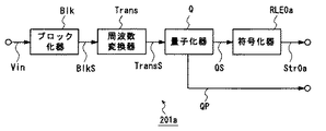
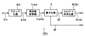
図30は従来の画像符号化装置を示すブロック図である。
この画像符号化装置201aは、入力された画像信号Vinを一定数の画素からなる単位領域(ブロック)に対応するようブロック化し、ブロック化された画像信号BlkSを出力するブロック化器Blkと、その出力BlkSを周波数変換して、各ブロックに対応する周波数成分TransSを出力する周波数変換器Transとを有している。ここで、上記ブロックは、画像信号の符号化処理の単位となる、ピクチャ(画像空間)内の所定サイズの領域であり、一定数の画素から構成されている。ここで、画像信号Vinは、複数のピクチャからなる動画像に対応するものである。
【0008】
また、上記画像符号化装置201aは、該周波数変換器の出力(周波数成分)TransSを量子化して、各ブロックに対応する量子化成分(量子化係数)QSを出力する量子化器Qと、該量子化器の出力(量子化成分)QSに対して可変長符号化処理を施す符号化器RLE0aとを有している。
【0009】
次に動作について説明する。
上記画像符号化装置201aに画像信号Vinが入力されると、ブロック化器Blkは、入力された画像信号Vinをブロック単位の画像信号に分割して、各ブロックに対応する画像信号(ブロック化画像信号)BlkSを生成する。周波数変換器Transは該ブロック化画像信号BlkSをDCT(離散コサイン変換)やウェーブレット変換などを用いて周波数成分TransSに変換する。量子化器Qは該周波数成分TransSを量子化パラメータQPに基づいて、所定の量子化ステップでもって量子化して量子化成分QSを出力するとともに、該量子化パラメータQPを出力する。そして、符号化器RLE0aは上記量子化成分QSに対して可変長符号化処理を施して符号化ストリームStr0aを出力する。
【0010】
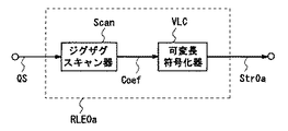
図31は上記画像符号化装置201aを構成する符号化器RLE0aを説明するためのブロック図である。
この符号化器RLE0aは、2次元の配列を有する量子化器Qの出力(量子化成分)QSを1次元の配列(つまり、所定の順序)を有する量子化成分Coefに変換するジグザグスキャン器Scanと、該ジグザグスキャン器Scanから出力される量子化成分Coefに対して可変長符号化処理を施す可変長符号化器VLCとを有している。
このような符号化器RLE0aに量子化器Qから出力された量子化成分QSが入力されると、ジグザグスキャン器Scanは、上記量子化器Qからの2次元の配列を有する量子化成分QSを1次元の配列(所定の順序)を有する量子化成分Coefに変換して出力する。
【0011】
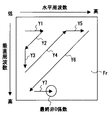
図43は上記ジグザグスキャン器Scanでの量子化成分QSの変換処理を具体的に説明するための図である。
量子化器Qから出力された量子化成分QSは、図43に示すように、2次元の配列、つまり、各量子化成分QSが、2次元の周波数領域Fr上にて、その水平方向の周波数の高さ及び垂直方向の周波数の高さに応じてマトリクス状に並ぶ配列を有している。
【0012】
ジグザグスキャン器Scanは、このように2次元の配列を有する量子化成分QSを、矢印Y1〜Y7で示すように、ジグザグにスキャンする処理を行って、1次元の配列を有する量子化成分Coefに変換する。つまりこのスキャン処理により、2次元の配列を有する複数の量子化成分QSに対して、上記スキャン経路に沿った所定の順序が設定される。
【0013】
そして、上記可変長符号化器VLCは、上記量子化成分の大きさを示す数値と符号(符号語)との対応を示す符号表を用いて、ジグザグスキャン器Scanから出力された量子化成分Coef に符号を割り当て、各ブロック毎に量子化成分を符号化ストリームStr0aに変換する。
【0014】
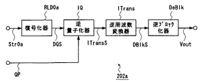
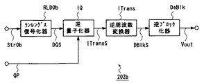
図32は、図30に示す画像符号化装置201aに対応する画像復号化装置202aを説明するためのブロック図である。
この画像復号化装置202aは、図30に示す従来の画像符号化装置201aから出力された符号化ストリームStr0aを復号化するものである。
この画像復号化装置202aは、上記画像符号化装置201aから出力された符号化ストリームStr0aに対して復号化処理を施す復号化器RLD0aと、該復号化器RLD0aの出力(復号量子化成分)DQSに対して逆量子化処理を施す逆量子化器IQとを有している。
【0015】
また、該画像復号化装置202aは、該逆量子化器IQの出力(復号周波数成分)ITransSに対して逆周波数変換処理を施す逆周波数変換器ITransと、該逆周波数変換器ITransの出力(復号ブロック化画像信号)DBlkSに基づいて、各ピクチャに対応する復号画像信号Voutを生成する逆ブロック化器DeBlkとを有している。
【0016】
次に動作について説明する。
上記画像復号化装置202aに上記画像符号化装置201aからの符号化ストリームStr0aが入力されると、上記復号化器RLD0aは、符号化ストリームStr0aに対して復号化処理を施して復号量子化成分DQSを出力する。この復号化器RLD0aの動作は、上記符号化器RLE0aの動作とは逆の動作である。
【0017】
さらに、逆量子化器IQは、量子化器Qの逆の動作、つまり復号量子化成分DQSを量子化パラメータQPを参照して逆量子化する動作を行って、復号周波数成分ITransSを出力する。また、逆周波数変換器ITransは、周波数変換器Transの逆動作、つまり復号周波数成分ITransSを逆DCTや逆ウェーブレット変換などを用いて各ブロックに対応する復号画像信号DBlkSに復元する動作を行う。そして、逆ブロック化器DeBlkは、上記各ブロックの復号画像信号DBlkSを統合して各ピクチャに対応する復号画像信号Voutを出力する。
【0018】
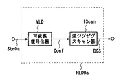
図33は上記画像復号化装置202aを構成する復号化器RLD0aを説明するためのブロック図である。
この復号化器RLD0aは、符号化ストリームStr0aに対して可変長復号化処理を施して、符号化ストリームStr0aに含まれる個々の符号に対応する量子化成分Coefを復号化する可変長復号化器VLDと、該可変長復号化器VLDから出力された、1次元の配列を有する復号量子化成分Coefから、2次元の配列を有する復号量子化成分DQSを復元する逆ジグザグスキャン器IScanとを有している。
【0019】
このような復号化器RLD0aでは、可変長復号化器VLDは可変長符号化器VLCとは逆の動作により、符号化ストリームStr0aを復号化して、符号(符号語)に対応する量子化成分Coefを出力する。そして、逆ジグザグスキャン器IScanはジグザグスキャン器Scanとは逆の動作により、上記可変長復号化器VLDから出力された1次元の配列を有する量子化成分Coefを、2次元の配列を有する復号量子化成分DQSに復元し、上記逆量子化器IQに出力する。
なお、特許文献1には、画像信号を輝度信号と色差信号に分けて可変長符号化処理を施す方法が開示されている。
【0020】
ところで、上記各ブロックに対応する、一定の順序が設定された複数の量子化係数は、その値が0でない係数(非0係数)の後に、その値が0である係数(0係数)が複数連続するといった冗長性の高いデータである。そこで、このような量子化係数の符号化には、従来から、その冗長な情報を排除して符号化する方法、例えば、連続する0係数の個数を示すラン値と、0係数の後に続く非0係数の値を示すレベル値を用いて量子化係数を符号化するランレングス符号化方法が用いられている。
【0021】
以下、ランレングス符号化方法を用いた従来の画像符号化装置について説明する。
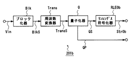
図34はランレングス符号化を行う従来の画像符号化装置を示すブロック図である。
この画像符号化装置201bは、図30に示す画像符号化装置201aにおける符号化器RLE0aに代えて、量子化器Qの出力(量子化成分)QSに対してランレングス符号化を施して符号化ストリームStr0bを出力するランレングス符号化器RLE0bを備えたものであり、その他の構成は、上記画像符号化装置201aと同一である。
【0022】
また、画像符号化装置201bの動作は、上記符号化器RLE0bの動作のみ、上記画像符号化装置201aのものと異なる。
【0023】
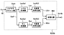
図35は上記画像符号化装置201bの符号化器RLE0bの具体的な構成を示すブロック図である。
このランレングス符号化器RLE0bは、上記符号化器RLE0aと同様、2次元の配列を有する量子化器Qの出力(量子化成分)QSを1次元の配列(つまり、所定の順序)を有する量子化成分Coefに変換するジグザグスキャン器Scanを有している。
【0024】
そして、このランレングス符号化器RLE0bは、連続する、その値が0である量子化成分(0係数)Coefの個数を計測して、該連続する0係数の個数を示すラン値Runを出力するラン計測器RunCalと、該0係数に続く、その値が0でない量子化成分Coef(非0係数)の値を計測して、該非0係数の値を示すレベル値Levを出力するレベル計測器LevCalとを有している。
【0025】
さらに、このランレングス符号化器RLE0bは、上記レベル計測器LevCalの出力であるレベル値Levに可変長符号化処理を施して符号列(レベル値符号列)LStrを出力する可変長符号化器LevVLCと、上記ラン計測器RunCalの出力であるラン値Runに可変長符号化処理を施して符号列(ラン値符号列)RStrを出力する可変長符号化器RunVLCと、上記レベル値符号列LStrとラン値符号列RStrとをブロック毎に多重化して多重符号化ストリームStr0bを出力する多重化器MUXとを有している。
【0026】
次に動作について説明する。
ジグザグスキャン器Scanは、上記量子化器Qから出力された2次元の配列を有する量子化成分QSを1次元の配列(所定の順序)を有する量子化成分Coefに変換して出力する。上記ジグザグスキャン器Scanでの量子化成分QSの変換処理は、上記画像符号化装置201aの符号化器RLE0aのものと同様に行われる。
【0027】
そして、上記ラン計測器RunCalは、上記ジグザグスキャン器Scanから出力された量子化成分Coefに基づいて、連続する0係数の個数を計測し、該個数を示すラン値Runを出力する。また、上記レベル計測器LevCalは、上記ジグザグスキャン器Scanから出力された量子化成分Coefに基づいて、上記連続する0係数に続く非0係数の値を計測し、この値を示すレベル値Levを出力する。
【0028】
ここで、上記ラン計測器RunCalは、処理対象となっている対象ブロックにおける最高周波数成分(非0係数のうちで最後のもの)を検出したとき、EOB(ブロックの最後)という特別な値を発生して、それ以降のより高い周波数成分はその値が全て0であることを通知する。
【0029】
さらに、上記可変長符号化器RunVLCは、上記ラン計測器RunCalの出力であるラン値Runに対して、符号表もしくは算術計算によって該ラン値に符号(符号語)を割り当てる可変長符号化処理を施して符号列RStrを出力し、また、上記可変長符号化器LevVLCは、上記レベル計測器LevCalの出力であるレベル値Levに対して符号表もしくは算術計算によって該レベル値に符号(符号語)を割り当てる可変長符号化処理を施して符号列LStrを出力する。
そして、多重化器MUXは、上記符号列LStrと符号列RStrとをブロック毎に多重化して多重符号化ストリームStr0bを出力する。
【0030】
ここで、上記符号列LStrと符号列RStrとの多重化処理は、例えば、ブロック毎に、対象ブロックに対応するすべてのラン値に対する符号列RStrの後に該対象ブロックに対応するすべてのレベル値に対する符号列LStrが続くよう、あるいは対象ブロックに対応するすべてのレベル値に対する符号列LStrの後に該対象ブロックに対応するすべてのラン値に対する符号列RStrが続くよう行われる。
【0031】
このように一定の順序を有する複数の量子化係数を、その値が0である量子化成分(0係数)Coefの個数を示すラン値Run、及び該0係数に続く、その値が0でない量子化成分Coef(非0係数)の値を示すレベル値Levを用いて符号化する画像符号化装置では、複数の量子化係数をその冗長な情報を排除して高い符号化効率で符号化することができる。
【0032】
図36は、図34に示す画像符号化装置201bに対応する画像復号化装置202bを説明するためのブロック図である。
この画像復号化装置202bは、図34に示す従来の画像符号化装置201bから出力された符号化ストリームStr0bを復号化するものである。
【0033】
この画像復号化装置202bは、図32に示す画像復号化装置202aにおける復号化供給RLD0aに代えて、上記画像符号化装置201bから出力された符号化ストリームStr0bに対して、ランレングス復号化処理を施すランレングス復号化器RLD0bを備えたものであり、その他の構成は、上記画像復号化装置202aのものと同一である。
【0034】
また、画像復号化装置202bの動作は、上記復号化器RLD0bの動作のみ、上記画像復号化装置202aのものと異なる。
図37は上記画像復号化装置202bのランレングス復号化器RLD0bの具体的な構成を示すブロック図である。
【0035】
このランレングス復号化器RLD0bは、上記画像符号化装置201bから出力された多重符号化ストリームStr0bから、レベル値に対応する符号列LStrとラン値に対応する符号列RStrとを分離する分離器DMUXと、符号列LStrに対して可変長復号化処理を施してレベル値Levを復元する可変長復号化器LevVLDと、符号列RStrに対して可変長復号化処理を施してラン値Runを復元する可変長復号化器RunVLDと、該レベル値Levとラン値Runにより表される1次元の配列を有する復号量子化成分から、2次元の配列を有する復号量子化成分DQSを復元する逆ジグザグスキャン器IScanとを有している。
【0036】
次に動作について説明する。
上記画像復号化装置202bでは、ランレングス復号化器RLD0bは、ランレングス符号化器RLE0bとは逆の動作を行う。つまり、ランレングス復号化器RLD0bは、多重符号化ストリームStr0bから、レベル値に対応する符号列LStrとラン値に対応する符号列RStrとを分離する。
【0037】
すると、可変長復号化器LevVLDは、可変長符号化器LevVLCとは逆の動作により、レベル値に対応する符号列LStrを復号化して、レベル値Levを出力する。また、可変長復号化器RunVLDは、可変長符号化器RunVLCとは逆の動作により、ラン値に対応する符号列RStrを復号化して、ラン値Runを出力する。
【0038】
逆ジグザグスキャン器IScanは、ジグザグスキャン器Scanとは逆の動作により、上記レベル値Levとラン値Runで表現される1次元の配列を有する量子化成分から、2次元の配列を有する復号量子化成分DQSを復元し、上記逆量子化器IQに出力する。ただし、この逆ジグザグスキャン器IScan(図37参照)は、図33に示す逆ジグザグスキャン器IScanと異なり、その入力はレベル値Levとラン値Runであるから、図37に示す逆ジグザグスキャン器IScanは、レベル値Levとラン値Runで表される係数を量子化成分Coefに変換する機能を有している。
【0039】
このように一定の順序を有する複数の量子化係数を復号化する復号化処理を、その値が0である量子化成分(0係数)Coefの個数を示すラン値Run、及び該0係数に続く、その値が0でない量子化成分Coef(非0係数)の値を示すレベル値Levを用いて行う画像復号化装置では、複数の量子化係数をランレングス符号化によりその冗長な情報を排除して高い符号化効率で符号化して得られた符号化データを、良好に復号化することができる。
【0040】
以下、ランレングス符号化方法を用いた従来の画像符号化装置の他の例について説明する。
図38は従来のランレングス符号化器を用いた画像符号化装置の他の例を示すブロック図である。MPEGやITU H.261、H.263などの規格および現在策定中のH.26L規格案(TML8)に準拠した従来の画像符号化装置は殆ど全てが図38に示すような構成になっている。
【0041】
この画像符号化装置201cは、図34に示す画像符号化装置201bと同様、ラン値及びレベル値を用いて量子化係数の符号化を行うものであるが、この画像符号化装置201cは、画像符号化装置201bのようにラン値及びレベル値を別々に可変長符号化するのではなく、ラン値とレベル値からなる対(ランレベル対)に対して可変長符号化処理を施すものである。
【0042】
すなわち、この画像符号化装置201cは、上記画像符号化装置201bと同様、画像信号Vinが入力されるブロック化器Blkと、その出力BlkSを周波数変換する周波数変換器Transと、該変換器の出力(周波数成分)TransSを量子化する量子化器Qとを有している。そして、この画像符号化装置201cは、該量子化器の出力(量子化成分)QSに対して、ラン値及びレベル値からなるランレベル対を可変長符号に変換するランレングス符号化を施すランレングス符号化器RLE0cとを有している。
【0043】
次に動作について説明する。
ブロック化器Blkは画像信号Vinをブロック単位の画像信号に分割して画素値成分(ブロック化画像信号)BlkSを生成する。周波数変換器Transは該画素値成分BlkSをDCT(離散コサイン変換)やウェーブレット変換などを用いて周波数成分TransSに変換する。量子化器Qは該周波数成分TransSを量子化パラメータQPに基づいて量子化して量子化成分QSを出力するとともに、該量子化パラメータQを出力する。ランレングス符号化器RLE0cは上記量子化成分QSに対してランレングス符号化を施して符号化ストリームStr0cを出力する。
【0044】
ここで、上記ブロックは、画像信号の符号化処理の単位となる、ピクチャ内の所定サイズの領域であり、一定数の画素から構成されている。また、ここでは、上記ランレングス符号化は、連続する、その値が0である量子化成分(0係数)の個数を示すラン値と、該0係数に続く、その値が0でない量子化成分(非0係数)の値を示すレベル値との対を可変長符号に変換する処理、言い換えると、上記ラン値とレベル値の対(ランレベル対)に1つの可変長符号(符号語)を割り当てる処理である。
【0045】
次に上記ランレングス符号化器RLE0cについて詳しく説明する。
図39は従来のランレングス符号化器RLE0cを示すブロック図である。
このランレングス符号化器RLE0cは、図35に示すランレングス符号化器RLE0bと同様、2次元の配列を有する量子化器Qの出力(量子化成分)QSを1次元の配列(つまり、所定の順序)を有する量子化成分Coefに変換するジグザグスキャン器Scanと、連続する、その値が0である量子化成分(0係数)Coefの個数を計測して、ラン値Runを出力するラン計測器RunCalと、該0係数に続く、その値が0でない量子化成分Coef(非0係数)の値を計測して、レベル値Levを出力するレベル計測器LevCalとを有している。
【0046】
そして、このランレングス符号化器RLE0cは、ラン計測器RunCal及びレベル計測器LevCalの出力に基づいて、レベル値Levとラン値Runの対に対応する符号番号Codeを符号表もしくは算術計算によって算出するランレベルコード変換器RunLevEncと、符号番号Codeに符号語を割り当て、上記画像信号Vinに対応する符号化ストリームStr0cを生成する可変長符号化器VLCとを有している。
【0047】
次に動作について説明する。
このランレングス符号化器RLE0cでは、ランレングス符号化器RLE0bと同様、ジグザグスキャン器Scanは、上記量子化器Qから出力された2次元の配列を有する量子化成分QSを1次元の配列(所定の順序)を有する量子化成分Coefに変換して出力する。
【0048】
図43は上記ジグザグスキャン器Scanでの量子化成分QSの変換処理を具体的に説明するための図である。
量子化器Qから出力された量子化成分QSは、図43に示すように、2次元の配列、つまり、各量子化成分QSが、2次元の周波数領域Fr上にて、その水平方向の周波数成分の大きさ及び垂直方向の周波数成分の大きさに応じてマトリクス状に並ぶ配列を有している。
【0049】
ジグザグスキャン器Scanは、このように2次元の配列を有する量子化成分QSを、矢印Y1〜Y7で示すように、ジグザグにスキャンする処理を行って、1次元の配列を有する量子化成分Coefに変換する。つまりこのスキャン処理により、2次元の配列を有する複数の量子化成分QSに対して、上記スキャン経路に沿った所定の順序が設定される。
【0050】
そして、上記ラン計測器RunCalは、上記ジグザグスキャン器Scanから出力された量子化成分Coefに基づいて、連続する0係数の個数を計測し、該個数を示すラン値Runを出力する。また、上記レベル計測器LevCalは、上記ジグザグスキャン器Scanから出力された量子化成分Coefに基づいて、上記連続する0係数に続く非0係数の値を計測し、この値を示すレベル値Levを出力する。ここで、上記ラン計測器RunCalは、処理対象となっている対象ブロックにおける最高周波数成分(非0係数のうちで最後のもの)を検出したとき、EOB(ブロックの最後)という特別な値を発生して、それ以降のより高い周波数成分はその値が全て0であることを通知する。
【0051】
さらに、上記ランレベルコード変換器RunLevEncは、上記ラン計測器RunCal及びレベル計測器LevCalの出力に基づいて、レベル値Levとラン値Runの対に対応する符号番号Codeを、符号表もしくは算術計算によって計算する。上記可変長符号化器VLCは、変換器RunLevEncにて得られた符号番号Codeを符号化し、つまり、符号番号Codeに符号語(ビット列)を割り当て、符号化ストリームStr0を生成する。
【0052】
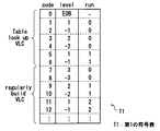
図42は上記ランレングス符号化器RLE0cで用いられる符号表の例を示している。図42に示す符号表(第1の符号化表)T1は、策定中のH.26L規格案(TML8)に準拠した色差信号のDC成分の符号表を示している。
この符号表T1は、レベル値とラン値から算術演算によって、レベル値とラン値の対に対応する符号番号を計算できる規則的生成可能部分(regularly build VLC)と、算術演算ではレベル値とラン値の対に対応する符号番号を計算できない非規則的部分(table look up VLC)とから構成されている。また、各符号番号Codeに対しては1対1に対応する符号語としてのビット列(図示せず)が割り当てられるが、値の小さい符号番号Codeには短い符号語が割り当てられる。
【0053】
次に上記画像符号化装置201cに対応する従来の画像復号化装置について説明する。
図40は従来のランレングス復号化器RLD0cを用いた画像復号化装置202cを示すブロック図である。
この画像復号化装置202cは、図39に示す従来の画像符号化装置201cから出力された符号化ストリームStr0cを復号化するものである。
【0054】
この画像復号化装置202cは、図36に示す画像復号化装置202bと同様、ラン値及びレベル値を用いて量子化係数の復号を行うものであるが、この画像復号化装置202cは、上記画像復号化装置202bのようにラン値及びレベル値の可変長復号化を、ラン値とレベル値とで別々に行うのではなく、ラン値とレベル値からなる対(ランレベル対)の可変長復号化を行うものである。
【0055】
すなわち、この画像復号化装置202cは、上記画像符号化装置201cから出力された符号化ストリームStr0cに対して、ラン値及びレベル値からなるランレベル対を用いたランレングス復号化処理を施すランレングス復号化器RLD0cを有している。さらに、上記画像復号化装置202cは、上記画像復号化装置202bと同様、該ランレングス復号化器RLD0cの出力(復号量子化成分)DQSに対して逆量子化処理を施す逆量子化器IQと、該逆量子化器IQの出力(復号周波数成分)ITransSに対して逆周波数変換処理を施す逆周波数変換器ITransと、該逆周波数変換器ITransの出力(復号画素値成分)DBlkSに基づいて、各ピクチャに対応する復号画像信号Voutを生成する逆ブロック化器DeBlkとを有している。
【0056】
次に動作について説明する。
上記画像復号化装置202cでは、ランレングス復号化器RLD0cは、ランレングス符号化器RLE0cとは逆の動作を行う。つまり、ランレングス復号化器RLD0cは、符号化ストリームStr0cに対してランレングス復号化処理を施して復号量子化成分DQSを出力する。逆量子化器IQは、量子化器Qとは逆の動作、つまり復号量子化成分DQSを量子化パラメータQPを参照して逆量子化する動作を行って、復号周波数成分ITransSを出力する。逆周波数変換器ITransは、周波数変換器Transとは逆の動作、つまり復号周波数成分ITransSを逆DCTや逆ウェーブレット変換などを用いて各ブロックに対応する復号画素値信号(復号ブロック化画像信号)DBlkSに復元する動作を行う。逆ブロック化器DeBlkは、上記各ブロックの復号画素値成分DBlkSを統合して各ピクチャに対応する復号画像信号Voutを出力する。
【0057】
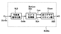
次に上記ランレングス復号化器RLD0cについて詳しく説明する。
図41は上記ランレングス復号化器RLD0cの具体的な構成を説明するためのブロック図である。
このランレングス復号化器RLD0cは、符号化ストリームStr0cに対して可変長復号化処理を施して、符号化ストリームStr0cに含まれる個々の符号(符号語)に対応する符号番号Codeを求める可変長復号化器VLDと、該符号番号Codeに対応する、レベル値Levとラン値Runの対を取得するランレベル取得器RunLevDecと、対をなすレベル値Levとラン値Runに基づいて、該レベル値Levとラン値Runにより表される1次元の配列を有する復号量子化成分から、2次元の配列を有する復号量子化成分DQSを復元する逆ジグザグスキャン器IScanとを有している。
【0058】
次に動作について説明する。
このランレングス復号化器RLD0cでは、可変長復号化器VLDは可変長符号化器VLCとは逆の動作により、符号化ストリームStr0cを復号化して、符号語(ビット列)に対応する符号番号Codeを出力する。ランレベル取得器RunLevDecは、ランレベルコード変換器RunLevEncとは逆の動作により、符号表を参照するかもしくは算術演算によって、符号番号Codeに対応する、対をなすレベルLev値とラン値Runを出力する。逆ジグザグスキャン器IScanはジグザグスキャン器Scanとは逆の動作により、上記対をなすレベル値Levとラン値Runで表現される1次元の配列を有する量子化成分から、2次元の配列を有する復号量子化成分DQSを復元し、上記逆量子化器IQに出力する。
【0059】
なお、特許文献2には、一定順序を有する複数の係数を、その値が0である量子化成分(0係数)Coefの個数を示すラン値Run、及び該0係数に続く、その値が0でない量子化成分Coef(非0係数)の値を示すレベル値Levを用いて符号化するランレングス符号化方法が開示されている。
【0060】
また、特許文献3には、デジタル映像データを予測符号化する方法において、差分動きベクトル値を可変長符号化テーブルを用いて符号化する際、差分動きベクトル値の大きさに応じて、可変長符号化テーブル(VLCテーブル)を切り換える方法が開示されている。
また、画素値を可変長符号化する他の方法として、画素値が所定の値を取る確率を用いて算術演算で可変長符号化を行う算術符号化が知られている。算術符号化では、確率から符号が導出できることから、個々の事象に対応する確率が記載された確率テーブルが上記VLCテーブルに相当する。なお、非特許文献1には、符号化対象の画素の画素値を、その周辺画素の画素値から予測した符号化対象画素の予測方法(コンテクスト)に基づいて確率テーブルを切り替えて算術符号化する方法が記載されている。
【0061】
【特許文献1】
特開平6−311534号公報
【特許文献2】
特開平6−237184号公報
【特許文献3】
特許第3144456号公報(特開平8−79088号公報)
【非特許文献1】
三木弼一編著,「MPEG−4のすべて」,工業調査会発行,1998年9月30日,初版第1刷発行,p.69−73
【0062】
【発明が解決しようとする課題】
上述した従来の画像符号化装置201aの符号化器RLE0aは、画像データの周波数成分を量子化して得られる複数の量子化係数を、一定の処理単位(ブロック)毎に可変長符号化するものであるが、該各量子化係数の大きさを示す数値情報と符号(符号語)との対応を複数示す、決められた符号表を用いるものであって、この符号化器による可変長符号化処理では、処理対象となるデータである量子化係数に存在する冗長性な情報を十分除去できておらず、圧縮率向上の余地が残っているという課題があった。
【0063】
また、従来の画像符号化装置201b,201cの符号化器RLE0b,RLE0cのように、複数の量子化係数の可変長符号化を、その値が0である量子化成分(0係数)Coefの個数を示すラン値や、該0係数に続く、その値が0でない量子化成分Coef(非0係数)の値を示すレベル値を用いて行うランレングス符号化器においても、可変長符号化処理の際の量子化係数に存在する冗長な情報の除去は、十分なものではなかった。
【0064】
また、従来の画像復号化装置202aの復号化器RLD0a、あるいは従来の画像復号化装置202b,202cのランレングス復号化器RLD0b,RLD0cは、量子化係数に対する可変長符号化処理の際、該量子化係数に存在する冗長性な情報を十分除去できない符号化器に対応するものであった。
【0065】
また、デジタル映像データを予測符号化する方法において、差分動きベクトル値を可変長符号化テーブルを用いて符号化する際、差分動きベクトル値の大きさに応じて、可変長符号化テーブル(VLCテーブル)を切り換える方法については、画像信号の周波数成分を量子化してなる量子化係数のように、複数の0係数が連続するような特性を有するデータに対する可変長符号化処理における効果的な符号化テーブルの切替は分かっていなかった。
【0066】
本発明は上記のような課題を解決するためになされたもので、可変長符号化処理の対象となるデータ(量子化係数)に存在する情報の冗長性を、量子化係数の特性や量子化係数に対する符号化処理の状況に応じて、より効果的に除去することができ、これにより画像信号などの圧縮率のさらなる向上を図ることができる可変長符号化方法及び可変長復号化方法を得ることを目的とする。
【0067】
【課題を解決するための手段】
本発明に係る可変長符号化方法は、複数の係数からなる係数データを符号化する可変長符号化方法であって、上記各係数に対して、該係数の大きさを表す数値情報と符号との対応を示す複数の符号表を用いて、上記係数データを複数の符号からなる符号化データに変換する符号化処理を施す符号化ステップを含み、該符号化ステップは、上記符号表を、上記符号化処理が施された処理済係数に関する情報、及び上記係数の生成に関するパラメータの少なくとも一方に応じて選択する符号表選択ステップと、上記符号化処理が施されていない未符号化係数に対して、上記選択された符号表を用いて符号を割り当てる符号割当ステップとを含むものであることを特徴とするものである。
【0068】
本発明は、上記可変長符号化方法において、上記係数は、画像データの周波数成分を、該画像データに応じた量子化ステップに基づいて量子化して得られたものであり、上記符号表選択ステップは、上記符号割当ステップで用いる符号表を、上記量子化ステップの大きさに応じて選択するものであることを特徴とするものである。
【0069】
本発明は、上記可変長符号化方法において、上記係数に対する符号化処理は、その値が0である連続する0係数の個数を示すラン値と、該0係数に続く非0係数の値を示すレベル値とを、それぞれ符号に変換するものであり、上記符号表選択ステップは、上記ラン値と符号との対応を示す複数の符号表から、上記量子化ステップの大きさに応じて1つの符号表を選択する第1の選択処理と、上記レベル値と符号との対応を示す複数の符号表から、上記量子化ステップの大きさに応じて1つの符号表を選択する第2の選択処理のうちの少なくとも一方の選択処理を行うものであり、上記符号割当ステップは、上記選択された符号表に基づいて、上記符号化処理が施されていない未符号化係数に対応するラン値及びレベル値の少なくとも一方に符号を割り当てるものであることを特徴とするものである。
【0070】
本発明は、上記可変長符号化方法において、上記係数に対する符号化処理は、その値が0である連続する0係数の個数を示すラン値と、該0係数に続く非0係数の値を示すレベル値とからなるランレベル対を符号に変換するものであり、上記符号表選択ステップは、上記量子化ステップの大きさに応じて、上記ランレベル対と符号との対応を示す複数の符号表から1つの符号表を選択するものであり、上記符号割当ステップは、上記選択された符号表に基づいて、上記符号化処理が施されていない未符号化係数に対応するランレベル対に符号を割り当てるものであることを特徴とするものである。
【0071】
本発明は、上記可変長符号化方法において、上記符号表選択ステップは、上記符号割当ステップで用いる符号表を、上記符号化処理が施された処理済係数に関する情報に応じて選択するものであることを特徴とするものである。
【0072】
本発明は、上記可変長符号化方法において、上記係数に対する符号化処理は、その値が0である連続する0係数の個数を示すラン値と、該0係数に続く非0係数の値を示すレベル値とを、それぞれ符号に変換するものであり、上記符号表選択ステップは、上記ラン値と符号との対応を示す複数の符号表から、符号化処理が施された処理済み係数に対応するラン値に関する情報に応じて1つの符号表を選択する第1の選択処理と、上記レベル値と符号との対応を示す複数の符号表から、符号化処理が施された処理済み係数に対応するレベル値に関する情報に応じて1つの符号表を選択する第2の選択処理のうちの少なくとも一方の選択処理を行うものであり、上記符号割当ステップは、上記選択された符号表に基づいて、上記符号化処理が施されていない未符号化係数に対応するラン値及びレベル値の少なくとも一方に符号を割り当てるものであることを特徴とするものである。
【0073】
本発明は、上記可変長符号化方法において、上記符号表選択ステップは、上記ラン値と符号との対応を示す複数の符号表から、符号が割当てられている処理済みラン値の個数に応じて1つの符号表を選択するものであり、上記符号割当ステップは、上記選択された符号表に基づいて、上記符号の割り当てられていない未符号化ラン値に符号を割り当てるものであることを特徴とするものである。
【0074】
本発明は、上記可変長符号化方法において、上記係数に対する符号化処理は、その値が0である連続する0係数の個数を示すラン値と、該0係数に続く非0係数の値を示すレベル値とからなるランレベル対を符号に変換するものであり、上記符号表選択ステップは、符号化処理が施された処理済み係数に対応するランレベル対に関する情報に応じて、上記ランレベル対と符号との対応を示す複数の符号表から1つの符号表を選択するものであり、上記符号割当ステップは、上記選択された符号表に基づいて、上記符号化処理が施されていない未符号化係数に対応するランレベル対に符号を割り当てるものであることを特徴とするものである。
【0075】
本発明は、上記可変長符号化方法において、上記係数は、画像データの周波数成分を、該画像データに応じた量子化ステップに基づいて量子化して得られたものであり、上記符号化ステップは、上記係数に対する符号化処理を、上記係数データを構成する複数の係数に対して、対応する画像データの周波数成分の高い順に符号が割当られるよう行うものであることを特徴とするものである。
【0076】
本発明は、上記可変長符号化方法において、上記係数に対する符号化処理は、一定数の係数からなるブロック毎に、その値が0である連続する0係数の個数を示すラン値と、該0係数に続く非0係数の値を示すレベル値とからなるランレベル対を符号に変換するものであり、上記符号表選択ステップは、上記符号化処理の対象となる対象ブロックにおける、符号化処理の施された処理済係数の個数と、該対象ブロックにおける、符号化処理の施されていない未符号化非0係数の個数との和に応じて、上記ランレベル対と符号との対応を示す複数の符号表から1つの符号表を選択するものであり、上記符号割当ステップは、上記選択された符号表に基づいて、上記対象ブロックにおける未符号化係数に対応するランレベル対に符号を割り当てるものであることを特徴とするものである。
【0077】
本発明は、上記可変長符号化方法において、上記係数に対する符号化処理は、その値が0である連続する0係数の個数を示すラン値と、該0係数に続く非0係数の値を示すレベル値とからなるランレベル対を符号に変換するものであり、上記符号化ステップは、上記ランレベル対と、これに対応する符号との対応を、該ランレベル対を形成するラン値とレベル値の組み合わせに応じて示す第1の符号表に基づいて、該第1の符号表における、ランレベル対と符号との対応を規則的に変更して、該第1の符号表とは、該ランレベル対と符号との対応が異なる第2の符号表を作成する符号表処理ステップを含み、上記符号表選択ステップは、上記第1及び第2の符号表の一方を、上記処理済係数に関する情報、及び上記係数の生成に関するパラメータの少なくとも一方に応じて選択するものであることを特徴とするものである。
【0078】
本発明は、上記可変長符号化方法において、上記第1及び第2の符号表は、各ランレベル対に、該ランレベル対を形成するレベル値が小さいほど、短い符号を対応付けたものであり、上記第2の符号表は、上記第1の符号表と比べて、平均的に、短い符号を対応付けられるランレベル対のレベル値が小さいものであることを特徴とするものである。
【0079】
本発明は、上記可変長符号化方法において、上記第1及び第2の符号表は、各ランレベル対に、該ランレベル対を形成するラン値が小さいほど、短い符号を対応付けたものであり、上記第2の符号表は、上記第1の符号表と比べて、平均的に、短い符号を対応付けられるランレベル対のラン値が小さいものであることを特徴とするものである。
【0080】
本発明は、上記可変長符号化方法において、上記係数に対する符号化処理は、ランレベル対の符号への変換を、一定数の係数からなるブロック毎に行うものであり、上記符号表処理ステップは、上記第2の符号表を、上記符号化処理の対象となる対象ブロックにおける、該符号化処理が施された処理済係数の数に応じて作成するものであることを特徴とするものである。
【0081】
本発明は、上記可変長符号化方法において、上記符号割当ステップは、上記ランレベル対に対する符号の割当を、画像データの周波数成分の高い係数に対応するランレベル対から順に行うものであることを特徴とするものである。
【0082】
本発明は、上記可変長符号化方法において、上記第2の符号表は、上記第1の符号表に含まれる、ランレベル対と符号との複数の対応のうちの、規則的に算出可能な対応のみを変更したものであることを特徴とするものである。
【0083】
本発明は、上記可変長符号化方法において、上記係数データを構成する係数は、画像データの周波数成分を、画像データに応じた量子化ステップに基づいて量子化して得られたものであり、上記符号表選択ステップは、上記第1の符号表と第2の符号表の切替えを、上記量子化ステップの大きさに基づいて行う符号表切替ステップであることを特徴とするものである。
【0084】
本発明は、上記可変長符号化方法において、上記符号表選択ステップは、上記第1の符号表と第2の符号表の切替を、切替え指示信号に基づいて行う符号表切替ステップであり、上記符号化ステップは、上記切替え指示信号の符号化処理を行うものであることを特徴とするものである。
【0085】
本発明は、上記可変長符号化方法において、上記係数に対する符号化処理は、ランレベル対の符号への変換を、一定の係数からなるブロック毎に行うものであり、上記符号表処理ステップは、上記第2の符号表を、符号化処理の対象となる対象ブロックにおける、符号化処理が施された処理済係数の個数と、該対象ブロックにおける、符号化処理が施されていない未符号化非0係数の個数との和に応じて作成するものであることを特徴とするものである。
【0086】
本発明に係る可変長符号化装置は、複数の係数からなる係数データを符号化する可変長符号化装置であって、上記各係数に対して、該係数の大きさを表す数値情報と符号との対応を示す複数の符号表を用いて、上記係数データを複数の符号からなる符号化データに変換する符号化処理を施す符号化部を含み、該符号化部は、上記符号表を、上記符号化処理が施された処理済係数に関する情報、及び上記係数の生成に関するパラメータの少なくとも一方に応じて選択する符号表選択部と、上記符号化処理が施されていない未符号化係数に対して、上記選択された符号表を用いて符号を割り当てる符号割当部とを有するものであることを特徴とするものである。
【0087】
本発明は、上記可変長符号化装置において、上記係数は、画像データの周波数成分を、該画像データに応じた量子化ステップに基づいて量子化して得られたものであり、上記符号表選択部は、上記符号割当部で用いる符号表を、上記量子化ステップの大きさに応じて選択するものであることを特徴とするものである。
【0088】
本発明は、上記可変長符号化装置において、上記符号表選択部は、上記符号割当部で用いる符号表を、上記符号化処理が施された処理済係数に関する情報に応じて選択するものであることを特徴とするものである。
【0089】
本発明は、上記可変長符号化装置において、上記係数に対する符号化処理は、その値が0である連続する0係数の個数を示すラン値と、該0係数に続く非0係数の値を示すレベル値とを、それぞれ符号に変換するものであり、上記符号表選択部は、上記ラン値と符号との対応を示す複数の符号表から、符号が割当てられている処理済みラン値の個数に応じて1つの符号表を選択するものであり、上記符号割当部は、上記選択された符号表に基づいて、上記符号の割り当てられていない未符号化ラン値に符号を割り当てるものであることを特徴とするものである。
【0090】
本発明は、 上記可変長符号化装置において、上記係数は、画像データの周波数成分を、該画像データに応じた量子化ステップに基づいて量子化して得られたものであり、上記符号化部は、上記係数に対する符号化処理を、上記係数データを構成する複数の係数に対して、対応する画像データの周波数成分の高い順に符号が割当られるよう行うものであることを特徴とするものである。
【0091】
本発明に係るプログラム記憶媒体は、複数の係数からなる係数データを符号化する可変長符号化処理をコンピュータにより行うプログラムを格納した記憶媒体であって、上記プログラムは、上記各係数に対して、該係数の大きさを表す数値情報と符号との対応を示す複数の符号表を用いて、上記係数データを複数の符号からなる符号化データに変換する符号化処理を施す符号化ステップを含み、該符号化ステップは、上記符号表を、上記符号化処理が施された処理済係数に関する情報、及び上記係数の生成に関するパラメータの少なくとも一方に応じて選択する符号表選択ステップと、上記符号化処理が施されていない未符号化係数に対して、上記選択された符号表を用いて符号を割り当てる符号割当ステップとを含むものであることを特徴とするものである。
【0092】
本発明に係る可変長復号化方法は、複数の係数からなる係数データを可変長符号化して得られた、複数の符号からなる符号化データを復号化する可変長復号化方法であって、上記各符号に対して、上記係数の大きさを表す数値情報と上記符号との対応を示す複数の符号表を用いて、上記符号化データを上記複数の係数からなる係数データに復元する復号化処理を施す復号化ステップを含み、該復号化ステップは、上記符号表を、上記復号化処理が施された処理済係数に関する情報、及び上記係数の生成に関するパラメータの少なくとも一方に応じて選択する符号表選択ステップと、上記復号化処理が施されていない未復号化符号に対応する数値情報を、上記選択された符号表を用いて取得する数値取得ステップとを含むものであることを特徴とするものである。
【0093】
本発明は、上記可変長復号化方法において、上記係数は、画像データの周波数成分を、該画像データに応じた量子化ステップに基づいて量子化して得られたものであり、上記符号表選択ステップは、上記数値取得ステップで用いる符号表を、上記量子化ステップの大きさに応じて選択するものであることを特徴とするものである。
【0094】
本発明は、上記可変長復号化方法において、上記符号に対する復号化処理は、上記符号を、その値が0である連続する0係数の個数を示すラン値と、該0係数に続く非0係数の値を示すレベル値とに復元するものであり、上記符号表選択ステップは、上記ラン値と符号との対応を示す複数の符号表から、上記量子化ステップの大きさに応じて1つの符号表を選択する第1の選択処理と、上記レベル値と符号との対応を示す複数の符号表から、上記量子化ステップの大きさに応じて1つの符号表を選択する第2の選択処理のうちの少なくとも一方の選択処理を行うものであり、上記数値取得ステップは、上記選択された符号表に基づいて、上記復号化処理が施されていない未復号化符号に対応するラン値及びレベル値の少なくとも一方を取得するものであることを特徴とするものである。
【0095】
本発明は、上記可変長復号化方法において、上記符号に対する復号化処理は、該符号を、その値が0である連続する0係数の個数を示すラン値と、該0係数に続く非0係数の値を示すレベル値とからなるランレベル対に復元するものであり、上記符号表選択ステップは、上記量子化ステップの大きさに応じて、上記ランレベル対と符号との対応を示す複数の符号表から1つの符号表を選択するものであり、上記数値取得ステップは、上記選択された符号表に基づいて、上記復号化処理が施されていない未復号化符号に対応するランレベル対を取得するものであることを特徴とするものである。
【0096】
本発明は、上記可変長復号化方法において、上記符号表選択ステップは、上記数値取得ステップで用いる符号表を、上記復号化処理により得られた処理済係数に関する情報に応じて選択するものであることを特徴とするものである。
【0097】
本発明は、上記可変長復号化方法において、上記符号に対する復号化処理は、該符号を、その値が0である連続する0係数の個数を示すラン値と、該0係数に続く非0係数の値を示すレベル値とに復元するものであり、上記符号表選択ステップは、上記ラン値と符号との対応を示す複数の符号表から、復号化処理により得られた処理済みラン値に関する情報に応じて1つの符号表を選択する第1の選択処理と、上記レベル値と符号との対応を示す複数の符号表から、復号化処理により得られた処理済みレベル値に関する情報に応じて1つの符号表を選択する第2の選択処理のうちの少なくとも一方の選択処理を行うものであり、上記数値取得ステップは、上記選択された符号表に基づいて、上記復号化処理が施されていない未復号化符号に対応するラン値及びレベル値の少なくとも一方を取得するものであることを特徴とするものである。
【0098】
本発明は、上記可変長復号化方法において、上記符号表選択ステップは、上記ラン値と符号との対応を示す複数の符号表から、復号化処理により得られた処理済みラン値の個数に応じて1つの符号表を選択するものであり、上記数値取得ステップは、上記選択された符号表に基づいて、上記復号化処理が施されていない未復号化符号に対応するラン値を取得するものであることを特徴とするものである。
【0099】
本発明は、上記可変長復号化方法において、上記符号に対する復号化処理は、符号を、その値が0である連続する0係数の個数を示すラン値と、該0係数に続く非0係数の値を示すレベル値とからなるランレベル対に復元するものであり、上記符号表選択ステップは、復号化処理により得られたランレベル対に関する情報に応じて、上記ランレベル対と符号との対応を示す複数の符号表から1つの符号表を選択するものであり、上記数値取得ステップは、上記選択された符号表に基づいて、上記復号化処理が施されていない未復号化符号に対応するランレベル対を取得するものであることを特徴とするものである。
【0100】
本発明は、上記可変長復号化方法において、上記係数は、画像データの周波数成分を、該画像データに応じた量子化ステップに基づいて量子化して得られたものであり、上記復号化ステップは、上記符号に対する復号化処理を、上記符号に対応する数値情報が、対応する画像データの周波数成分の高いものから順に取得されるよう行うものであることを特徴とするものである。
【0101】
本発明は、上記可変長復号化方法において、上記符号に対する復号化処理は、上記係数データを構成する一定数の係数からなるブロック毎に、上記符号を、その値が0である連続する0係数の個数を示すラン値と、該0係数に続く非0係数の値を示すレベル値とからなるランレベル対に復元するものであり、上記符号表選択ステップは、上記復号化処理の対象となる対象ブロックにおける、該ブロックの復号化処理により得られた処理済係数の個数と、該対象ブロックにおける、該ブロックの復号化処理では未だ得られていない未復号化非0係数の個数との和に応じて、上記ランレベル対と符号との対応を示す複数の符号表から1つの符号表を選択するものであり、上記数値取得ステップは、上記選択された符号表に基づいて、上記対象ブロックにおける未復号化係数に対応するランレベル対を取得するものであることを特徴とするものである。
【0102】
本発明は、上記可変長復号化方法において、上記符号に対する復号化処理は、該符号化データを構成する符号を、その値が0である連続する0係数の個数を示すラン値と、該0係数に続く非0係数の値を示すレベル値とからなるランレベル対に復元するものであり、上記復号化ステップは、上記ランレベル対と、これに対応する符号との対応を、該ランレベル対を形成するラン値とレベル値の組み合わせに応じて示す第1の符号表に基づいて、該第1 の符号表における、ランレベル対と符号との対応を規則的に変更して、該第1の符号表とは、該ランレベル対と符号との対応が異なる第2の符号表を作成する符号表処理ステップを含み、上記符号表選択ステップは、上記第1及び第2の符号表の一方を、上記処理済係数に関する情報、及び上記係数の生成に関するパラメータの少なくとも一方に応じて選択するものであることを特徴とするものである。
【0103】
本発明は、上記可変長復号化方法において、上記第1及び第2の符号表は、各ランレベル対に、該ランレベル対を形成するレベル値が小さいほど、短い符号を対応付けたものであり、上記第2の符号表は、上記第1の符号表と比べて、平均的に、短い符号を対応付けられるランレベル対のレベル値が小さいものであることを特徴とするものである。
【0104】
本発明は、上記可変長復号化方法において、上記第1及び第2の符号表は、各ランレベル対に、該ランレベル対を形成するラン値が小さいほど、短い符号を対応付けたものであり、上記第2の符号表は、上記第1の符号表と比べて、平均的に、短い符号を対応付けられるランレベル対のラン値が小さいものであることを特徴とするものである。
【0105】
本発明は、上記可変長復号化方法において、上記符号に対する復号化処理は、該符号のランレベル対への復元を、上記係数データを構成する一定数の係数からなるブロック毎に行うものであり、上記符号表処理ステップは、上記第2の符号表を、上記復号化処理の対象となる対象ブロックにおける、該復号化処理により得られた処理済係数の数に応じて作成するものであることを特徴とするものである。
【0106】
本発明は、上記可変長復号化方法において、上記数値取得ステップは、上記符号に対応するランレベル対の取得を、対応する画像データの周波数成分の高いランレベル対から順に行うものであることを特徴とするものである。
【0107】
本発明は、上記可変長復号化方法において、上記第2の符号表は、上記第1の符号表に含まれる、ランレベル対と符号との複数の対応のうちの、規則的に算出可能な対応のみを変更したものであることを特徴とするものである。
【0108】
本発明は、上記可変長復号化方法において、上記係数データを構成する係数は、画像データの周波数成分を、画像データに応じた量子化ステップに基づいて量子化して得られたものであり、上記符号表選択ステップは、上記第1の符号表と第2の符号表の切替えを、上記量子化ステップの大きさに基づいて行うものであることを特徴とするものである。
【0109】
本発明は、上記可変長復号化方法において、上記符号表選択ステップは、上記第1の符号表と第2の符号表の切替を、切替え指示信号に基づいて行う符号表切替ステップを含むものであり、上記復号化ステップは、上記切替え指示信号の復号化処理を行うものであることを特徴とするものである。
【0110】
本発明は、上記可変長復号化方法において、上記符号に対する復号化処理は、符号のランレベル対への復元を、上記係数データを構成する一定の係数からなるブロック毎に行うものであり、上記符号表処理ステップは、上記第2の符号表を、復号化処理の対象となる対象ブロックにおける、該ブロックに対する復号化処理により得られた処理済係数の個数と、該対象ブロックにおける、該ブロックに対する復号化処理では未だ得られていない未復号化非0係数の個数との和に応じて作成するものであることを特徴とするものである。
【0111】
本発明に係る可変長復号化装置は、複数の係数からなる係数データを可変長符号化して得られた、複数の符号からなる符号化データを復号化する可変長復号化装置であって、上記各符号に対して、上記係数の大きさを表す数値情報と上記符号との対応を示す複数の符号表を用いて、上記符号化データを上記複数の係数からなる係数データに復元する復号化処理を施す復号化部を備え、該復号化部は、上記符号表を、上記復号化処理が施された処理済係数に関する情報、及び上記係数の生成に関するパラメータの少なくとも一方に応じて選択する符号表選択部と、上記復号化処理が施されていない未復号化符号に対応する数値情報を、上記選択された符号表を用いて取得する数値取得部とを有するものであることを特徴とするものである。
【0112】
本発明は、上記可変長復号化装置において、上記係数は、画像データの周波数成分を、該画像データに応じた量子化ステップに基づいて量子化して得られたものであり、上記符号表選択部は、上記数値取得部で用いる符号表を、上記量子化ステップの大きさに応じて選択するものであることを特徴とするものである。
【0113】
本発明は、上記可変長復号化装置において、上記符号表選択部は、上記数値取得部で用いる符号表を、上記復号化処理により得られた処理済係数に関する情報に応じて選択するものであることを特徴とするものである。
【0114】
本発明は、上記可変長復号化装置において、上記符号に対する復号化処理は、該符号を、その値が0である連続する0係数の個数を示すラン値と、該0係数に続く非0係数の値を示すレベル値とに復元するものであり、上記符号表選択部は、上記ラン値と符号との対応を示す複数の符号表から、復号化処理により得られた処理済みラン値の個数に応じて1つの符号表を選択するものであり、上記数値取得部は、上記選択された符号表に基づいて、上記復号化処理が施されていない未復号化符号に対応するラン値を取得するものであることを特徴とするものである。
【0115】
本発明は、上記可変長復号化装置において、上記係数は、画像データの周波数成分を、該画像データに応じた量子化ステップに基づいて量子化して得られたものであり、上記復号化部は、上記符号に対する復号化処理を、上記符号に対応する数値情報が、対応する画像データの周波数成分の高いものから順に取得されるよう行うものであることを特徴とするものである。
【0116】
本発明に係るプログラム記憶媒体は、複数の係数からなる係数データを可変長符号化して得られた、複数の符号からなる符号化データを復号化する可変長復号化処理をコンピュータにより行うプログラムを格納した記憶媒体であって、上記プログラムは、上記各符号に対して、上記係数の大きさを表す数値情報と上記符号との対応を示す複数の符号表を用いて、上記符号化データを上記複数の係数からなる係数データに復元する復号化処理を施す復号化ステップを含み、該復号化ステップは、上記符号表を、上記復号化処理が施された処理済係数に関する情報、及び上記係数の生成に関するパラメータの少なくとも一方に応じて選択する符号表選択ステップと、上記復号化処理が施されていない未復号化符号に対応する数値情報を、上記選択された符号表を用いて取得する数値取得ステップとを含むものであることを特徴とするものである。
【0117】
【発明の実施の形態】
まず、本発明の基本原理について説明する。
一般に、量子化ステップが粗い場合は量子化成分の絶対値が小さくなるために、ラン(0係数が続く長さ)が長くなり、レベル値(非0係数の値)の絶対値が小さくなる。逆に、量子化ステップが密な場合は量子化成分の絶対値が大きくなるために、ランが短くなりレベル値の絶対値が大きくなる。
【0118】
また、処理対象ブロックにて既に多くの量子化成分の可変長符号化が完了しており、未符号化の量子化成分の数が少ない場合は、その未符号化の量子化成分の数を上回るラン値は発生し得ない。このため、そのラン値とレベル値との対を符号表から除去すれば、符号化効率が向上する。
【0119】
このような観点から、本発明は、量子化係数に対する可変長符号化処理あるいは可変長復号化処理の状況や量子化係数の生成に関するパラメータ(量子化パラメータ)に応じて、量子化係数の大きさを示す数値情報と符号との対応を示す符号表を切替えるものであり、これにより、可変長符号化処理の対象となるデータ(量子化係数)に存在する冗長な情報をより効果的に除去できるものである。
【0120】
例えば、上記符号表の切替えは、従来の可変長符号化あるいは復号化処理で用いられる符号表(第1の符号表)と、該第1の符号表に基づいて作成した、処理対象データに対して最適化された第2の符号表との一方を、量子化係数に対する処理状況に応じて選択することにより行われる。但し、必ずしも第1の符号表に基づいて第2の符号表を作成する必要はなく、選択の候補となる符号表は、処理対象データに適した符号表であればよい。
以下、本発明の実施の形態について、図1から図25を用いて説明する。
【0121】
(実施の形態1)
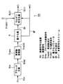
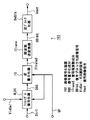
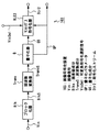
図1は本発明の実施の形態1による画像符号化装置を説明するためのブロック図である。
この実施の形態1の画像符号化装置101は、図34に示す従来の画像符号化装置201bにおける、量子化器Qの出力(量子化成分)QSに対して可変長符号化処理を施して符号化ストリームStr0bを出力するランレングス符号化器RLE0bに代えて、上記量子化器Qの出力QSに対して、量子化パラメータQP及びVLC選択信号VlcSelに基づいて、可変長符号化処理を施して符号化ストリームStr1を出力するランレングス符号化器RLE1を備えたものである。
【0122】
ここで、上記量子化パラメータQPは量子化ステップの大きさを表すパラメータであり、量子化ステップは量子化パラメータQPにほぼ比例する。つまり、量子化パラメータQPが大きい場合は、量子化成分の絶対値が小さくなるために、量子化成分の0ラン(その値が0の成分が連続して並ぶ長さ)が長くなり、レベル値の絶対値が小さくなる。
【0123】
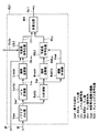
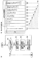
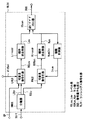
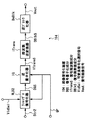
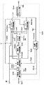
図2は上記ランレングス符号化器RLE1の具体的な構成を説明するためのブロック図である。
このランレングス符号化器RLE1は、図35に示す従来のランレングス符号化器RLE0bと同様、2次元の配列を有する量子化器Qの出力(量子化成分)QSを1次元の配列(つまり、所定の順序)を有する量子化成分Coefに変換するジグザグスキャン器Scanと、連続する、その値が0である量子化成分(0係数)Coefの個数を計測して、該連続する0係数の個数を示すラン値Runを出力するラン計測器RunCalと、該0係数に続く、その値が0でない量子化成分Coef(非0係数)の値を計測して、該非0係数の値を示すレベル値Levを出力するレベル計測器LevCalとを有している。
【0124】
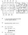
図3(a)は、1ブロックに対応する量子化成分Q1〜Q16の2次元の配列を示し、図3(b)は、ジグザグスキャン器Scanによる上記量子化成分Q1〜Q16のスキャン経路を矢印A1〜A15で示している。ここで量子化成分Q1は、画像信号の周波数成分のDC成分を量子化したものであり、量子化成分Q2〜Q16は、画像信号の周波数成分のAC成分を量子化したものである。また、図3(c)は、ジグザグスキャン器Scanによるジグザグスキャンにより得られた量子化成分Q1〜Q16の1次元の配列(符号化の順序)を示し、図3(d)は、量子化成分Q1〜Q16の大きさを示す具体的な数値の1次元の配列を示している。
【0125】
そして、上記ランレングス符号化器RLE1は、上記レベル計測器LevCalの出力であるレベル値Levを並べ替える順序並替器Lreodrと、上記ラン計測器RunCalの出力であるラン値Runを並べ替える順序並替器Rreodrと、上記ラン計測器RunCalの出力に基づいて、対象ブロックにおける未符号化係数の個数Cnumを計測して出力する個数計測器NumClcとを有している。図3(e)は、図3(c),(d)に示す配列を有する量子化成分の数値から得られるラン値及びレベル値の順序を示し、図3(f)は、並替え後のラン値及びレベル値の順序を示している。
【0126】
また、ランレングス符号化器RLE1は、順序並替器Lreodrの出力ROLevに対して、上記量子化パラメータQP及び切替え信号VldSelに基づいて、可変長符号化処理を施して符号列(レベル値符号列)LStrを出力する可変長符号化器LVLCと、順序並替器Rreodrの出力RORunに対して、上記未符号化係数の個数Cnumに基づいて、可変長符号化処理を施して符号列(ラン値符号列)RStrを出力する可変長符号化器RVLCと、上記符号列LStrと符号列RStrとをブロック毎に多重化して多重符号化ストリームStr1を出力する多重化器MUXとを有している。
【0127】
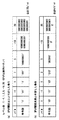
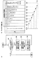
図4は、上記可変長符号化器LVLCの可変長符号化処理を説明する図であり、図4(a)はレベル値の可変長符号化処理のフローの説明図、図4(b)は該レベル値の可変長符号化処理で用いる符号表の説明図である。
図4(b)は、レベル値(Level)の配列Alevと、量子化パラメータQPが閾値より小さい場合の符号(符号語)の配列Ca1と、量子化パラメータQPが閾値以上である場合の符号(符号語)の配列Ca2とを示している。
【0128】
ここで、符号表L1は、レベル値(Level)の配列Alevと、量子化パラメータQPが閾値より小さい場合の符号(符号語)の配列Ca1とから構成されており、量子化パラメータQPが閾値より小さい場合の、レベル値(Level)と符号との対応を複数示している。符号表L2は、レベル値(Level)の配列Alevと、量子化パラメータQPが閾値以上である場合の符号(符号語)の配列Ca2とから構成されており、量子化パラメータQPが閾値以上である場合の、レベル値(Level)と符号との対応を複数示している。
【0129】
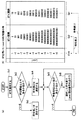
図5は、上記可変長符号化器RVLCの可変長符号化処理を説明する図であり、図5(a)はラン値の可変長符号化処理のフローの説明図、図5(b)は該ラン値の可変長符号化処理で用いる符号表の説明図である。
【0130】
図5(b)は、ラン値(Run)の配列Arunと、未符号化0係数の個数が1である場合の符号(符号語)の配列Cb1と、未符号化0係数の個数が2である場合の符号(符号語)の配列Cb2と、未符号化0係数の個数が3である場合の符号(符号語)の配列Cb3と、未符号化0係数の個数が4である場合の符号(符号語)の配列Cb4と、未符号化0係数の個数が5である場合の符号(符号語)の配列Cb5と、未符号化0係数の個数が6である場合の符号(符号語)の配列Cb6と、未符号化0係数の個数が7である場合の符号(符号語)の配列Cb7と、未符号化0係数の個数が8以上である場合の符号(符号語)の配列Cb8とを示している。
【0131】
ここで、符号表R1は、ラン値(Run)の配列Arunと、未符号化0係数の個数が1である場合の符号(符号語)の配列Cb1とから構成されており、未符号化0係数の個数が1である場合の、ラン値(Run)と符号との対応を複数示している。同様に、符号表R2,R3,R4,R5,R6,R7はそれぞれ、ラン値(Run)の配列Arunと、未符号化0係数の個数が2,3,4,5,6,7である場合の符号(符号語)の配列Cb2,Cb3,Cb4,Cb5,Cb6,Cb7とから構成されており、未符号化0係数の個数が2,3,4,5,6,7である場合の、ラン値(Run)と符号との対応を複数示している。さらに、符号表R8は、ラン値(Run)の配列Arunと、未符号化0係数の個数が8以上である場合の符号(符号語)の配列Cb8とから構成されており、未符号化0係数の個数が8以上である場合の、ラン値(Run)と符号との対応を複数示している。
【0132】
次に動作について説明する。
この実施の形態1の画像符号化装置101では、ブロック化器Blk,周波数変換器Trans,及び量子化器Qは、従来の画像符号化装置201a(図30参照)あるいは画像符号化装置201b(図34参照)のものと同様に動作する。
【0133】
つまり、画像符号化装置101aに画像信号Vinが入力されると、ブロック化器Blkは、入力された画像信号Vinをブロック単位に分割して、各ブロックに対応する画像信号(画素値成分)BlkSを生成する。周波数変換器Transは、該画素値成分BlkSをDCT(離散コサイン変換)やウェーブレット変換などを用いて周波数成分TransSに変換する。量子化器Qは該周波数成分TransSを量子化パラメータQPに基づいて、所定の量子化ステップでもって量子化して量子化成分QSを出力するとともに、該量子化パラメータQPを出力する。ランレングス符号化器RLE1は上記量子化成分QSに対して可変長符号化処理を施して符号化ストリームStr1を出力する。
【0134】
以下、上記ランレングス符号化器RLE1の動作について詳しく説明する。
ジグザグスキャン器Scanは、上記量子化器Qから出力された量子化成分QS(つまり図3(a)に示す2次元の配列を有する複数の量子化係数Q1〜Q16)のジグザグスキャンを行って、該量子化成分QSを量子化成分Coefに変換して出力する。ここで、上記量子化成分QSのジグザグスキャンは、図3(a)に示す2次元の配列を有する複数の量子化係数Q1〜Q16を、図3(b)の矢印A1〜A15で示す経路に沿ってスキャンして、複数の量子化係数Q1〜Q16の配列を図3(c)に示す1次元の配列(処理順序)に変換するものである。なお、図3(d)は、上記ジグザグスキャンが施された複数の量子化係数Q1〜Q16の具体的な数値の配列(20,-10,5,0,2,0,0,0,1,0,0,0,-1,0,0,1)を示している。
【0135】
ラン計測器RunCalは、上記ジグザグスキャン器Scanから出力された量子化成分Coefに基づいて、連続する0係数の個数を計測し、該個数を示すラン値Runを出力する。図3(e)には、ラン計測器RunCalから順次出力される具体的なラン値がその出力される順(0,0,0,1,3,3,2)で示されている。一方、レベル計測器LevCalは、上記ジグザグスキャン器Scanから出力された量子化成分Coefに基づいて、上記連続する0係数に続く非0係数の値を計測し、この値を示すレベル値Levを出力する。図3(e)には、レベル計測器LevCalから順次出力される具体的なレベル値がその出力される順(20,-10,5,2,1,-1,1)で示されている。
【0136】
順序並替器Rreodrは、上記ラン計測器RunCalから順次出力されたラン値の順序を、出力順とは逆の順序に並べ替える。図3(f)には、順序並替器Rreodrにより並べ替えられた具体的なラン値の順序(2,3,3,1,0,0,0)が示されている。また、個数計測器NumClcは、ラン計測器RunCalから出力されるラン値Runに基づいて、未符号化係数の個数を計測し、該未符号化係数の個数(未符号化係数数)Cnumを出力する。一方、順序並替器Lreodrは、上記レベル計測器LevCalから順次出力されたレベル値の順序を、出力順とは逆の順序に並べ替える。図3(f)には、順序並替器Lreodrにより並べ替えられた具体的なレベル値の順序(1,-1,1,2,5,-10,20)で示されている。
【0137】
可変長符号化器RVLCは、上記個数計測器NumClcから出力された未符号化0係数数Cnumに基づいて、上記順序並替器Rreodrの出力である並べ替えられたラン値RORunに対して、該ラン値と符号(符号語)との対応を示す複数の符号表を用いてラン値RORunに符号(符号語)を割り当てる可変長符号化処理を施して、ラン値符号列RStrを出力する。一方、可変長符号化器LVLCは、量子化器Qからの量子化パラメータQP及び外部からの、可変長符号化の選択を指示する選択信号VlcSelに基づいて、上記順序並替器Lreodrの出力である並べ替えられたレベル値ROLevに対して、該レベル値と符号(符号語)との対応を示す複数の符号表を用いてレベル値ROLevに符号(符号語)を割り当てる可変長符号化処理を施して、レベル値符号列LStrを出力する。
そして、多重化器MUXは、上記レベル値符号列LStrとラン値符号列RStrとをブロック毎に多重化して多重符号化ストリームStr1を出力する。
【0138】
ここで、上記レベル値符号列LStrとラン値符号列RStrとの多重化処理は、例えば、ブロック毎に、対象ブロックに対応するすべてのラン値に対する符号列RStrの後に該対象ブロックに対応するすべてのレベル値に対する符号列LStrが続くよう、あるいは対象ブロックに対応するすべてのレベル値に対する符号列LStrの後に該対象ブロックに対応するすべてのラン値に対する符号列RStrが続くよう行われる。
【0139】
以下、可変長符号化器LVLCの動作について図4を用いて詳述する。
可変長符号化器LVLCは、量子化器Qからの量子化パラメータQPを取得し(ステップSa1)、該取得した量子化パラメータQPの値が、該可変長符号化器LVLCに保持されている量子化パラメータQPの閾値以上であるか否かの判定を行う(ステップSa2)。
【0140】
この判定の結果、取得した量子化パラメータQPの値が、量子化パラメータQPの閾値より小さい場合は、レベル値の配列Alevと符号(符号語)の配列Ca1とからなる符号表L1(図4(b)参照)を選択し(ステップSa3)、取得した量子化パラメータQPの値が、量子化パラメータQPの閾値以上である場合は、レベル値の配列Alevと符号(符号語)の配列Ca2とからなる符号表L2(図4(b)参照)を選択する(ステップSa4)。
【0141】
その後、可変長符号化器LVLCは、対象ブロック内に未符号化レベル値Levがあるか否かを判定し(ステップSa5)、対象ブロック内に未符号化レベル値Levがあれば、選択した符号表を用いて、レベル値Levの符号化処理、つまり、該レベル値に、対応する符号を割り当てる処理を行い(ステップSa6)、その後上記ステップSa5処理を行う。一方、上記ステップSa5での判定の結果、対象ブロックに未符号化レベル値Levがない場合は、上記レベル値Levに対する可変長符号化処理を終了する。
【0142】
なお、可変長符号化器LVLCは、上記VLC選択信号VlcSelにより予め特定の符号表を用いた可変長符号化処理が指定されている場合は、量子化パラメータQPの大きさに拘わらず、該特定の符号表を用いて、レベル値に対する可変長符号化処理を行う。
【0143】
次に、可変長符号化器RVLCの動作について図5を用いて詳述する。
可変長符号化器RVLCは、個数計測器NumClcの出力(未符号化係数の個数)Cnumに基づいて対象ブロック内に未符号化非0係数があるか否かを判定し(ステップSb1)、この判定の結果、未符号化非0係数がある場合は、個数計測器NumClcからの出力Cnumに基づいて対象ブロック内の未符号化0係数の個数を計測する(ステップSb2)。
【0144】
そして、可変長符号化器RVLCは、計測した未符号化0係数の個数に応じて、符号表を選択する(ステップSb3)。具体的には、未符号化0係数の個数が1である場合は、ラン値の配列Arunと符号(符号語)の配列Cb1とからなる符号表R1(図5(b)参照)を選択する。同様に、未符号化0係数の個数が2である場合は符号表R2を、該個数が3である場合は符号表R3を、該個数が4である場合は符号表R4を選択する。さらに未符号化0係数の個数が5である場合は符号表R5を、該個数が6である場合は符号表R6を、該個数が7である場合は符号表R7を選択する。そして、未符号化0係数の個数が8以上である場合は符号表R8を選択する。
【0145】
次に、可変長符号化器RVLCは、選択した符号表を用いて、ラン値Runの符号化処理、つまり、該ラン値に、対応する符号を割り当てる処理を行い(ステップSb4)、その後、上記ステップSb1の判定処理を行う。
なお、上記ステップSb1の判定の結果、未符号化非0係数がない場合は、上記ラン値に対する可変長符号化処理を終了する。
【0146】
続いて、上記のようにレベル値の可変長符号化の際に量子化パラメータに基づいて符号表を選択することにより、符号化効率が向上する点につき、具体的な例を挙げて説明する。
【0147】
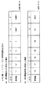
図6は、量子化パラメータQPが比較的小さい場合、つまり、順序並替器Lreodrから出力される、並べ替えられたレベル計測器LevCalの出力(レベル値)が、図3(f)に示すように1,-1,1,2,5,-10,20である場合に、これらのレベル値に割り当てられる符号の合計ビット数を示している。
【0148】
量子化パラメータQPが閾値以上であると判断して符号表L2を用いた場合には、各レベル値には、図6(a)に示すように符号(符号語)が割り当てられ、割り当てられる符号の合計ビット数は、75ビットとなる。
【0149】
一方、量子化パラメータQPが閾値より小さいと判断して符号表L1を用いた場合には、各レベル値には、図6(b)に示すように符号(符号語)が割り当てられ、割り当てられる符号の合計ビット数は、47ビットとなる。
【0150】
このように、量子化パラメータQPの値が比較的小さい場合には、値が大きい量子化係数の出現頻度が高くなるので、符号表L2に比べて、絶対値が比較的大きいレベル値にも、平均的に短い符号が対応付けられている符号表L1を選択することが、符号化効率を向上する上で有効である。
【0151】
図7は、量子化パラメータQPが比較的大きい場合、つまり、順序並替器Lreodrから出力される、並べ替えられたレベル計測器LevCalの出力(レベル値)が、図3(f)に示すものとは異なり、1,-1,1,1,1,-2,3である場合に、これらのレベル値に割り当てられる符号の合計ビット数を示している。
【0152】
量子化パラメータQPが閾値以上であると判断して符号表L2を用いた場合には、各レベル値には、図7(a)に示すように符号(符号語)が割り当てられ、割り当てられる符号の合計ビット数は、15ビットとなる。
【0153】
一方、量子化パラメータQPが閾値より小さいと判断して符号表L1を用いた場合には、各レベル値には、図7(b)に示すように符号(符号語)が割り当てられ、割り当てられる符号の合計ビット数は、17ビットとなる。
このように、量子化パラメータQPの値が比較的大きい場合には、値が大きい量子化係数の出現頻度が低くなるので、符号表L1に比べて、絶対値が比較的小さいレベル値に、集中的に短い符号が対応付けられている符号表L2を選択することが、符号化効率を向上する上で有効である。
【0154】
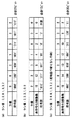
図8は、ラン計測器RunCalから出力されるラン値が、図3(e)に示すように0,0,0,1,3,3,2である場合に、これらのラン値に割り当てられる符号の合計ビット数を示している。
上記ランレングス符号化器RLE1のようなラン値の並替、及び符号表の切り替えを行わないで、常に図5に示す符号表R8を用いる場合は、各ラン値には、図8(a)に示すように符号(符号語)が割り当てられ、割り当てられる符号の合計ビット数は、21ビットとなる。
【0155】
上記ランレングス符号化器RLE1のようにラン値の並替、及び未符号化0係数数に応じた符号表の切り替えを行う場合は、各ラン値には、図8(b)に示すように符号(符号語)が割り当てられ、割り当てられる符号の合計ビット数は、13ビットとなる。ここで、1つのラン値に符号を割当てる度に、未符号化係数数は、直前に符号化したラン値に1加えた値だけ減少している。これは、単独のあるいは連続する0係数の後には非0係数が必ず1つあるからである。また、順序並替器Rreodrから出力される、1つのブロックに対応する並べ替えられた複数のラン値から得られる未符号化0係数は15である。これは、処理対象となるブロックでは、非0係数が必ず1つはあるためである。
【0156】
上記ランレングス符号化器RLE1のようなラン値の並替は行わず、未符号化0係数数に応じた符号表の切り替えのみを行う場合は、各ラン値には、図8(c)に示すように符号(符号語)が割り当てられ、割り当てられる符号の合計ビット数は、20ビットとなる。
【0157】
このように本実施の形態1の画像符号化装置101では、画像信号の周波数成分を量子化して得られた量子化係数を、連続する、その値が0である量子化成分(0係数)Coefの個数を示すラン値Runと、該0係数に続く、その値が0でない量子化成分Coef(非0係数)の値を示すレベル値Levとを用いて符号化するランレングス符号化器RLE1を備えたので、量子化係数をその冗長な情報を排除して高い符号化効率で符号化することができる。
【0158】
また、本実施の形態1のランレングス符号化器RLE1では、上記量子化パラメータQPの大きさに応じて符号表を選択し、選択した符号表を用いてレベル値の可変長符号化を行う可変長符号化器LVLCを備えたので、レベル値に割り当てられる符号の合計ビット数を削減することができる。また、上記ランレングス符号化器RLE1では、一定の処理順序が付与された量子化係数から計測された複数のラン値を、周波数成分の高い量子化係数に対応するものから順に並べ替える順序並替器Rreodrと、対象ブロックにおける未符号化0係数の個数に応じて符号表を選択し、選択した符号表を用いて、該並べ替えられたラン値の可変長符号化を行う可変長符号化器RVLCとを備えているので、ラン値に割り当てられる符号の合計ビット数を効果的に削減して、符号化効率の向上を図ることができる。
【0159】
なお、上記実施の形態1では、可変長符号化器RVLCは、対象ブロックにおける未符号化0係数の個数(つまり個数計測器NumClcの出力Cnum)に応じて符号表を選択するものとしているが、可変長符号化器RVLCは、個数計測器NumClcの出力Cnumだけでなく、上記VLC選択信号VlcSelに基づいて符号表を選択するものとしてもよい。例えば、可変長符号化器RVLCは、VLC選択信号VlcSelにより予め特定の符号表を用いた可変長符号化処理が指定されている場合は、対象ブロックにおける未符号化0係数の個数に拘わらず、該特定の符号表を用いて、ラン値に対する可変長符号化処理を行うものとしてもよい。
【0160】
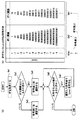
(実施の形態2)
図9は本発明の実施の形態2による画像復号化装置を説明するためのブロック図である。
この実施の形態2の画像復号化装置102は、例えば、実施の形態1の画像符号化装置101から出力された符号化ストリームStr1を復号化するものである。
そして、この画像復号化装置102は、図36に示す従来の画像復号化装置202bにおける、入力された符号化ストリームStr0bに対して可変長復号化処理を施すランレングス復号化器RLD0bに代えて、入力された符号化ストリームStr1に対して、量子化パラメータQP及びVLD選択信号VldSelに基づいて、可変長復号化処理を施して量子化係数を復元するランレングス復号化器RLD1を備えたものであり、その他の構成は、図36に示す画像復号化装置202bと同一である。
【0161】
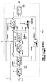
図10は上記ランレングス復号化器RLD1の具体的な構成を説明するためのブロック図である。
このランレングス復号化器RLD1は、図37に示す従来のランレングス復号化器RLD0bと同様、上記画像符号化装置101から出力された多重符号化ストリームStr1から、レベル値に対応する符号列LStrとラン値に対応する符号列RStrとを分離する分離器DMUXを有している。
【0162】
そして、上記ランレングス復号化器RLD1は、多重符号化ストリームStr1から分離されたレベル値符号列LStrに対して、上記量子化パラメータQP及びVLD選択信号VldSelに基づいて、可変長復号化処理を施して、レベル値ROLevを復元する可変長復号化器LVLDと、多重符号化ストリームStr1から分離されたラン値符号列RStrに対して、未復号化係数の個数に基づいて、可変長復号化処理を施してラン値RORunを復元する可変長復号化器RVLDとを有している。
【0163】
上記ランレングス復号化器RLD1は、上記可変長復号化器LVLDの出力であるレベル値ROLevに対して、符号化側の順序並替器Lreodrとは逆の並べ替え処理を施して、符号化側のレベル計測器の出力Levを復元する順序逆並替器LIreodrと、上記可変長復号化器RVLDの出力であるラン値RORunに対して、符号化側の順序並替器Rreodrとは逆の並べ替え処理を施して、符号化側のラン計測器の出力Runを復元する順序逆並替器RIreodrと、該順序逆並替器RIreodrの出力Runに基づいて、対象ブロックにおける未復号化係数の個数Cnumを計測して出力する個数計測器NumClcとを有している。
さらに、上記ランレングス復号化器RLD1は、上記レベル値Levとラン値Runにより表される1次元の配列を有する復号量子化成分から、2次元の配列を有する復号量子化成分DQSを復元する逆ジグザグスキャン器IScanとを有している。
【0164】
図11は、上記可変長復号化器LVLDの可変長復号化処理を説明する図であり、図11(a)はレベル値を復元する可変長復号化処理のフローの説明図、図11(b)は該可変長復号化処理で用いる符号表の説明図である。なお、レベル値の可変長復号化処理で用いる符号表L1及びL2はそれぞれ、上記実施の形態1のランレングス符号化器RLE1でのレベル値の符号化処理で用いた符号表L1及びL2と同一のものである。
【0165】
図12は、上記可変長復号化器RVLDの可変長復号化処理を説明する図であり、図12(a)はラン値を復元する可変長復号化処理のフローの説明図、図12(b)は該可変長復号化処理で用いる符号表の説明図である。なお、ラン値の可変長復号化処理で用いる符号表R1〜R8はそれぞれ、上記実施の形態1のランレングス符号化器RLE1でのラン値の符号化処理で用いた符号表R1〜R8と同一のものである。
【0166】
次に動作について説明する。
上記画像復号化装置102に、例えば、実施の形態1の画像符号化装置101からの多重符号化ストリームStr1が入力されると、上記ランレングス復号化器RLD1は、符号化ストリームStr1に対して復号化処理を施して復号量子化成分DQSを出力する。このランレングス復号化器RLD1の動作は、上記ランレングス符号化器RLE1の動作とは逆の動作である。
【0167】
つまり、ランレングス復号化器RLD1では、分離器DMUXは、入力された多重符号化ストリームStr1から、レベル値に対応するレベル値符号列LStrとラン値に対応するラン値符号列RStrとを分離して、それぞれ可変長復号化器LVLDと可変長復号化器RVLDに出力する。
【0168】
可変長復号化器LVLDは、量子化器Qからの量子化パラメータQP及び外部からの、可変長復号化の選択を指示するVLD選択信号VldSelに基づいて、上記分離器DMUXからのレベル値符号列LStrに対して、該レベル値と符号(符号語)との対応を示す複数の符号表を用いて、各符号(符号語)に対応するレベル値ROLevを取得して順序逆並替器LIreodrに出力する。一方、可変長復号化器RVLDは、上記個数計測器NumClcから出力された未復号化係数数Cnumに基づいて、上記分離器DMUXからのラン値符号列RStrに対して、該ラン値と符号(符号語)との対応を示す複数の符号表を用いて、各符号(符号語)に対応するラン値ROLevを取得して順序逆並替器RIreodrに出力する。
【0169】
順序逆並替器LIreodrは、上記可変長復号化器LVLDの出力であるレベル値ROLevに対して、符号化側の順序並替器Lreodrとは逆の並べ替え処理を施して、符号化側のレベル計測器の出力Levを復元する。一方、順序逆並替器RIreodrは、上記可変長復号化器RVLDの出力であるラン値RORunに対して、符号化側の順序並替器Rreodrとは逆の並べ替え処理を施して、符号化側のラン計測器の出力Runを復元する。また、個数計測器NumClcは、該順序逆並替器RIreodrの出力Runに基づいて、対象ブロックにおける未復号化係数の個数Cnumを計測して上記可変長復号化器RVLDに出力する。
【0170】
そして、逆ジグザグスキャン器IScanは、ジグザグスキャン器Scanとは逆の動作により、上記レベル値Levとラン値Runで表現される1次元の配列を有する量子化成分から、2次元の配列を有する復号量子化成分DQSを復元し、上記逆量子化器IQに出力する。
【0171】
以下、可変長復号化器LVLDの動作について図11を用いて詳述する。
可変長復号化器LVLDは、画像符号化装置101の量子化器Qからの量子化パラメータQPを取得し(ステップSc1)、該取得した量子化パラメータQPの値が、該可変長復号化器LVLDに保持されている量子化パラメータQPの閾値以上であるか否かの判定を行う(ステップSc2)。
【0172】
この判定の結果、取得した量子化パラメータQPの値が、量子化パラメータQPの閾値より小さい場合は、レベル値の配列Alevと符号(符号語)の配列Ca1とからなる符号表L1(図11(b)参照)を選択し(ステップSc3)、取得した量子化パラメータQPの値が、量子化パラメータQPの閾値以上である場合は、レベル値の配列Alevと符号(符号語)の配列Ca2とからなる符号表L2(図11(b)参照)を選択する(ステップSc4)。
【0173】
その後、可変長復号化器LVLDは、対象ブロック内に未復号化レベル値Levがあるか否かを判定し(ステップSc5)、対象ブロック内に未復号化レベル値Levがあれば、選択した符号表を用いて、レベル値Levを復元する復号化処理、つまり、符号に対応するレベル値を取得する処理を行い(ステップSc6)、その後上記ステップSc5処理を行う。一方、上記ステップSc5での判定の結果、対象ブロックに未復号化レベル値Levがない場合は、上記レベル値Levを復元する可変長復号化処理を終了する。
【0174】
なお、可変長復号化器LVLDは、上記VLD選択信号VldSelにより予め特定の符号表を用いた可変長復号化処理が指定されている場合は、量子化パラメータQPの大きさに拘わらず、該特定の符号表を用いて、レベル値を復元する可変長復号化処理を行う。
【0175】
次に、可変長復号化器RVLDの動作について図12を用いて詳述する。
可変長復号化器RVLDは、個数計測器NumClcの出力(未復号化係数の個数)Cnumに基づいて、対象ブロック内に未復号化非0係数があるか否かを判定し(ステップSd1)、この判定の結果、未復号化非0係数がある場合は、上記未復号化係数の個数Cnumに基づいて、対象ブロック内の未復号化0係数の個数を計測する(ステップSd2)。
【0176】
そして、可変長復号化器RVLDは、計測した未復号化0係数の個数に応じて、符号表を選択する(ステップSd3)。具体的には、未復号化0係数の個数が1である場合は、ラン値の配列Arunと符号(符号語)の配列Cb1とからなる符号表R1(図12(b)参照)を選択する。同様に、未復号化0係数の個数が2である場合は符号表R2を、該個数が3である場合は符号表R3を、該個数が4である場合は符号表R4を選択する。さらに未復号化0係数の個数が5である場合は符号表R5を、該個数が6である場合は符号表R6を、該個数が7である場合は符号表R7を選択する。そして、未復号化0係数の個数が8以上である場合は符号表R8を選択する。
【0177】
次に、可変長復号化器RVLDは、選択した符号表を用いて、ラン値Runを復元する復号化処理、つまり、各符号に対応するラン値を取得する処理を行い(ステップSd4)、その後、上記ステップSd1の判定処理を行う。
また、上記ステップSd1の判定の結果、未復号化非0係数がない場合は、上記ラン値を復元する可変長復号化処理を終了する。
【0178】
なお、この実施の形態2の画像復号化装置102では、逆量子化器IQ,逆周波数変換器ITrans,及び逆ブロック化器DeBlkは、従来の画像復号化装置202a(図32参照)あるいは画像復号化装置202b(図36参照)とのものと同様に動作する。
【0179】
つまり、逆量子化器IQは、量子化器Qの逆の動作、つまり復号量子化成分DQSを量子化パラメータQPを参照して逆量子化する動作を行って、復号周波数成分ITransSを出力する。また、逆周波数変換器ITransは、周波数変換器Transの逆動作、つまり復号周波数成分ITransSを逆DCTや逆ウェーブレット変換などを用いて、各ブロックに対応する復号周波数成分ITransSを各ブロックに対応する復号画素値信号DBlkSに復元する動作を行う。そして、逆ブロック化器DeBlkは、上記各ブロックの復号画素値成分DBlkSを統合して各ピクチャに対応する復号画像信号Voutを出力する。
【0180】
このように本実施の形態2の画像復号化装置102では、符号化データを構成するラン符号列RStr及びレベル符号列LStrをそれぞれ、連続する0係数Coefの個数を示すラン値Run、及び該0係数に続く非0係数の値を示すレベル値Levに変換し、該ラン値及びレベル値に基づいて量子化係数を復元するランレングス復号化器RLD1を備えたので、量子化係数をその冗長な情報を排除して高い符号化効率で符号化することができる可変長符号化処理に対応した復号化処理を良好に行うことができる。
【0181】
また、本実施の形態2のランレングス復号化器RLD1では、量子化パラメータQPの大きさに応じて符号表を選択し、選択した符号表を用いてレベル値を復元する可変長復号化を行う可変長復号化器LVLDを備えたので、レベル値に割り当てられる符号の合計ビット数を削減したレベル値符号列を良好に復号化することができる。
【0182】
また、上記ランレングス復号化器RLD1では、対象ブロックにおける未復号化0係数の個数に応じて符号表を選択し、選択した符号表を用いて、並べ替えられたラン値に対応する符号列を復号化する可変長復号化器RVLDと、該復号化により得られたラン値を、ランレングス符号化器RLD1でのラン値の並替え処理とは逆の順序で並べ替える順序逆並替器RIreodrとを備えたので、ラン値に割り当てられる符号の合計ビット数を効果的に削減したラン値符号化列を良好に復号化することができる。
【0183】
なお、上記実施の形態2では、可変長復号化器RVLDは、対象ブロックにおける未復号化0係数の個数(つまり個数計測器NumClcの出力Cnum)に応じて符号表を選択するものとしているが、可変長復号化器RVLDは、個数計測器NumClcの出力Cnumだけでなく、上記VLD選択信号VldSelに基づいて符号表を選択するものとしてもよい。例えば、可変長復号化器RVLDは、VLD選択信号VldSelにより予め特定の符号表を用いた可変長復号化処理が指定されている場合は、対象ブロックにおける未復号化0係数の個数に拘わらず、該特定の符号表を用いて、ラン値を復元する可変長復号化処理を行うものとしてもよい。
【0184】
(実施の形態3)
図13は本発明の実施の形態3による画像符号化装置を説明するためのブロック図である。
この実施の形態3の画像符号化装置103は、図38に示す従来の画像符号化装置201cにおける、量子化器Qの出力(量子化成分)QSに対して可変長符号化処理を施して符号化ストリームStr0cを出力するランレングス符号化器RLE0cに代えて、上記量子化器Qの出力QSに対して、量子化パラメータQPあるいはVLC選択信号VlcSelに基づいて、可変長符号化処理を施して符号化ストリームStr2を出力するランレングス符号化器RLE2を備えたものである。この実施の形態3の画像符号化装置103におけるその他の機器は、従来の画像符号化装置201cにおけるものと同一である。
【0185】
すなわち、上記ランレングス符号化器RLE2は、従来の上記ランレングス符号化器RLE0cと同様、ラン値とレベル値との対(以下、ランレベル対という。)と、これに対応する符号との対応関係を、該ラン値とレベル値の組み合わせに応じて示す第1の符号表T1(図42参照)を有している。そして、このランレングス符号化器RLE2は、上記第1の符号表に基づいて、該第1の符号表における、ラン値とレベル値の対と符号との対応関係を規則的に変更して、該第1の符号表とは該対応関係が異なる第2の符号表を作成し、上記第1及び第2の符号表を、上記量子化器Qから出力される量子化パラメータQP、あるいは外部からのVLC選択信号VlcSelに基づいてその一方を選択するとともに、上記処理対象データにおける係数に関連するラン値及びレベル値の対に、選択された符号表に基づいて符号を割り当てるものである。
【0186】
ここで、上記量子化パラメータQPは量子化ステップの大きさを表すパラメータであり、量子化ステップは量子化パラメータQPにほぼ比例する。つまり、量子化パラメータQPが大きい場合は、量子化成分の絶対値が小さくなるために、量子化成分の0ラン(その値が0の成分が連続して並ぶ長さ)が長くなり、レベル値の絶対値が小さくなる。従ってこの場合は、ラン値が大きくレベル値が小さいランレベル対に小さい符号が割り当てられている符号表を選択することにより符号化効率を向上することができる。逆に、量子化パラメータQPが小さい場合は、量子化成分の絶対値が大きくなるために、ラン値が小さくレベル値が大きいランレベル対に対して小さい符号が割り当てられている符号表を選択することにより、符号化効率を向上することができる。
【0187】
また、上記ランレングス符号化器RLE2は、画像符号化装置103の外部からのVLC選択信号VlcSelが入力されたとき、該選択信号VlcSelにより、符号化処理で用いられる符号表を選択するものである。このため、画像特性(画像の動き量の大きさ,その動きの複雑さ、あるいは絵柄の細かさなど)によって適切な符号表を外部から選択したり、この画像符号化装置103側で、符号表を1つしか備えていない画像復号化装置にて復号化可能なストリームを作成する場合には、画像符号化装置103では、VLC選択信号VlcSelにより、常に所定の符号表が用いられるようにすることができる。つまり、符号表の切替えを行わずに、1つの符号表のみを用いて可変長符号化処理を行うこともできる。
【0188】
図14は上記ランレングス符号化器RLE2の具体的な構成を説明するためのブロック図である。
上記ランレングス符号化器RLE2は、従来のランレングス符号化器RLE0c(図39参照)と同様、2次元の配列を有する量子化器Qの出力(量子化成分)QSを1次元の配列(つまり、所定の順序)を有する量子化成分Coefに変換するジグザグスキャン器Scanと、連続する、その値が0である量子化成分(0係数)Coefの個数を計測して、ラン値Runを出力するラン計測器RunCalと、該0係数に続く、その値が0でない量子化成分Coef(非0係数)の値を計測して、レベル値Levを出力するレベル計測器LevCalとを有している。
【0189】
そして、この実施の形態3では、ランレングス符号化器RLE2は、上記ラン計測器RunCalの出力(ラン値)Runを、ラン値Runの上位の桁を表すラン値Run1と、該ラン値Runの下位の桁を表すラン値Run2とに分離する変換処理を、上記量子化パラメータQPあるいはVLC選択信号VlcSelに基づいて行うラン変換器RunConvと、上記レベル計測器LevCalの出力(レベル値)Levを、レベル値Levの上位の桁を表すレベル値Lev1と、該レベルLevの下位の桁を表すレベル値Lev2とに分離する変換処理を、上記量子化パラメータQPあるいはVLC選択信号VlcSelに基づいて行うレベル変換器LevConvとを有している。
【0190】
また、上記ランレングス符号化器RLE2は、ラン値Run1とレベル値Lev1の対(以下、ランレベル上位桁対という。)に対応する符号番号Codeを符号表もしくは算術計算によって計算するランレベルコード変換器RunLevEncと、このようにして得られた、ランレベル上位桁対と符号番号Codeとの対応関係に基づいて、処理対象となる対象ブロックに対応する、より高い周波数成分に対応するランレベル上位桁対に、より小さい符号番号が対応するよう、上記ランレベル上位桁対の順序を並べ替える処理を、上記量子化パラメータQPあるいはVLC選択信号VlcSelに応じて行い、並べ替えられたランレベル上位桁対に対応する符号番号ReOdrCodeを出力する順序並替器ReOdrとを有している。
【0191】
さらに、上記ランレングス符号化器RLE2は、上記ラン値Runから符号化済量子化成分(符号化済係数)の個数を計算して、符号化済係数個数Posを出力する位置計算器PosClcと、上記ランレベル上位桁対と符号番号ReOdrCodeとの対応関係に基づいて、レベル値Lev2およびラン値Run2から、第2の符号表により示される、ランレベル対に対応する符号番号ExtCodeを出力する番号変換器CodeTransと、該符号番号ExtCodeにビット列(符号語)を割り当てて符号化ストリームStrを生成する可変長符号化器VLCとを有している。
【0192】
なお、上記ランレングス符号化器RLE2における、ジグザグスキャン器Scan,ラン計測器RunCal,レベル計測器LevCal,及び可変長符号化器VLCは、図39に示す従来のランレングス符号化器RLE0cにおけるものと同一のものである。
【0193】
次に作用効果について説明する。
ジグザグスキャン器Scanは、2次元の配列を有する量子化成分QSを、1次元の配列を有する、つまり順番が設定された量子化成分Coefに変換して出力する。ラン計測器RunCalは、連続する0成分(その値が0である量子化成分)Coefの個数を計測し、該個数を示すラン値Runを出力する。また、レベル計測器LevCalは非0成分(0成分に続く、その値が0でない量子化成分)Coefの値を計測し、該非0成分の値を示すレベル値Levを出力する。
【0194】
ラン変換器RunConvは上記ラン値Runを、ラン値Runの上位の桁を表すラン値Run1と、ラン値Runの下位の桁を表すラン値Run2に分離する変換処理を行う。レベル変換器LevConvはレベル値Levを、レベル値Levの上位の桁を表すレベル値Lev1と、レベル値Levの下位の桁を表すレベル値Lev2とに分離する変換処理を行う。
【0195】
ランレベルコード変換器RunLevEncは、レベル値Lev1とラン値Run1の対(ランレベル上位対)に対応する符号番号Codeを、図42に示す符号表(第1の符号表)もしくは算術計算によって計算する。順序並替器ReOdrは、上記ランレベル上位桁対の順序を並べ替える処理を、上記量子化パラメータQPあるいはVLC選択信号VlcSelに基づいて行い、並べ替えられたランレベル上位桁対に対応する符号番号ReOdrCodeを出力する。上記ランレベル上位桁対の順序を並べ替える処理により、ランレベルコード変換器RunLevEncにて得られた、ランレベル上位桁対と符号番号Codeとの対応関係が、処理対象となる対象ブロックにおけるより高い周波数成分に対応するランレベル上位桁対に、より小さい符号番号が対応する対応関係に変換される。
【0196】
位置計算器PosClcは、ラン値Runから符号化済成分の個数を計算し、該符号化済係数個数Posを出力する。番号変換器CodeTransは、上記ランレベル上位桁対と符号番号ReOdrCodeとの対応関係に基づいて、レベル値Lev2およびラン値Run2から、ランレベル対に対応する符号番号ExtCodeを出力する。このとき、番号変換器CodeTransでは、位置計算器PosClcから出力された符号化済係数個数Posが、未符号化成分がいくつあるかを計算するために使用される。
【0197】
ここで、番号変換器CodeTransから出力される、ランレベル対に対応する符号番号ExtCodeは、ランレベル対と符号番号との対応関係が第1の符号表のものとは異なる第2の符号表に基づいて得られたものである。また、この第2の符号表は、上記順序並替器ReOdrでの並替え処理により、ランレベル対と符号番号の対応関係が第1の符号表とは異なる符号表を作成し、さらに、上記順序並替器ReOdrにて作成された符号表を、番号変換器CodeTransにて、符号化済係数個数Posに基づいて、未符号化成分の個数を超えるラン値Runに相当する、ランレベル対と符号番号との対応関係が含まれないものとすることにより、作成されたものである。
そして、可変長符号化器VLCは該符号番号ExtCodeにビット列(符号語)を割り当てて符号化ストリームStr2を生成する。
【0198】
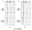
図15は上記ランレングス符号化器RLE2にて、第1の符号表に基づいて作成される第2の符号表の例を示している。ここで、第1の符号表は、従来のランレングス符号化器RLE0cで利用される、図42に示す符号表と同一のものである。なお、第1及び第2の符号表では、符号番号Codeに対して1対1に対応するビット列(符号語)が割り当てられるが、値が小さい符号番号Codeには短い符号語が割り当てられることは言うまでもない。
【0199】
図15(a)は、第2の符号表の一例として、量子化パラメータQPが小さい場合に適した第2の符号表T2aを示している。
この第2の符号表T2aは以下のようにして作成される。
まず、レベル値Lev1としてレベル値Levの1/2の値が割り当てられ、レベル値Lev2にはLev1×2−Levの絶対値が割り当てられる。
【0200】
ここで、レベル値Levが奇数である場合は、レベル値Levよりその絶対値が1大きい偶数を2で除算した値がレベル値Lev1とされる。つまり、レベル値Levが正であるとき、レベル値Lev1には(Lev+1)の1/2の値が割り当てられ、レベル値Levが負であるとき、レベル値Lev1には(Lev-1)の1/2の値が割り当てられる。
そして、レベル値Lev1とラン値Runの組み合わせに応じて、第1の符号表(図42参照)から、レベル値Lev1とラン値Runの対に対応する符号番号Codeが取得される。
【0201】
さらに、Lev値が正の場合は次式(1)に基づいて、Lev値が負の場合は次式(2)に基づいて、レベル値Lev1とラン値Runの対に対応する符号番号Codeが変換される。第2の符号表T2aは、この変換の結果得られる符号番号とランレベル対との対応関係を示すものである。
2×(Code-Lev2)−1 ・・・(1)
2×(Code-Lev2)・・・(2)
【0202】
例えば、図42の符号表(第1の符号表)のランレベル対(level=−2,run=1)に着目すると、このランレベル対に対応する符号番号codeは、図42に示す第1の符号表T1で示される値「10」から図15(a)の第2の符号表T2aで示される「12」に変換される。
【0203】
すなわち、この場合、ランレベル対(Lev,Run)は、(−2,1)であるため、Lev1及びLev2は、以下のように算出される。
Lev1 =Lev・(1/2)=−1
Lev2 =|Lev1・2−Lev|=|−1・2−(−2)|=0
従って、(Lev1,Run)は、(−1,1)となり、このランレベル対は、第1の符号表(図42)では、符号番号(code =6)に対応する。
【0204】
そこで、式(2)を用いて、ランレベル対(Lev ,Run)=(−2,1)に対応する符号番号を計算すると、
2×(Code-Lev2)=2×(6−0)=12
となる。
【0205】
図15(a)の符号表は、図42に示す符号表(第1の符号表)に比べて、ラン値が小さくレベル値が大きいランレベル対に対して、より小さい符号番号(即ち短い符号語)が割り当てられるのが特徴であり、量子化パラメータQPが小さい場合に適している。
【0206】
図15(b)は、第2の符号表の他の例として、量子化パラメータQPが大きい場合に適した第2の符号表T2bを示している。
【0207】
この第2の符号表T2bは以下のようにして作成される。
まず、ラン値Run1としてラン値Runの1/2の値が割り当てられ、ラン値Run2にはRun1×2−Runの絶対値が割り当てられる。ここで、ラン値Runが奇数である場合は、ラン値Run1には、(Run+1)の1/2の値の整数部分が割り当てられる。
そして、レベル値Levとラン値Run1の組み合わせに応じて、第1の符号表(図42参照)から、レベル値Levとラン値Run1の対に対応する符号番号Codeを取得される。
【0208】
さらに、Lev値が正の場合は次式(3)に基づいて、Lev値が負の場合は次式(4)に基づいて、レベル値Levとラン値Run1の対に対応する符号番号Codeが変換される。第2の符号表T2bは、この変換の結果得られる符号番号とランレベル対との対応関係を示すものとなる。
2×(Code+Run2)−1 ・・・(3)
2×(Code+Run2)−2 ・・・(4)
例えば、図42の符号表(第1の符号表)のランレベル対(level=−1,run=2)に着目すると、このランレベル対に対応する符号番号codeは、図42に示す第1の符号表T1で示される値「12」から図15(b)の第2の符号表T2bで示される「10」に変換される。
【0209】
すなわち、この場合、ランレベル対(Lev,Run)は、(−1,2)であるため、Run1及びRun2は、以下のように算出される。
Run1 = Run・(1/2)=1
Run2 =|Run1・2−Run| =|1・2 −2|=0
従って、(Lev,Run1)は、(−1,1)となり、このランレベル対は、第1の符号表(図42)では、符号番号(code =6)に対応する。
【0210】
そこで、式(4)を用いて、ランレベル対(Lev ,Run)=(−1,2)に対応する符号番号を計算すると、
2×(Code+Run2)=2×(6−0)−2=10
となる。
【0211】
図15(b)に示す第2の符号表T2bは、図42に示す符号表(第1の符号表)T1に比べて、ラン値が大きくレベル値が小さいランレベル対に対して、より小さい符号番号(即ち短い符号語)が割り当てられるのが特徴であり、量子化パラメータQPが大きい場合に適している。
【0212】
図16は上記ランレングス符号化器RLE2にて、第1の符号表に基づいて作成される第2の符号表の他の例を示している。ここで、第1の符号表は、従来のランレングス符号化器RLE0cで利用される、図42に示す符号表T1と同一のものである
【0213】
番号変換器CodeTransでは、位置計算器PosClcから出力された符号化済係数個数Posに基づいて処理対象ブロックに存在する未符号化成分数(符号化処理が施されていない係数の個数)が計算される。そして、第1の符号表から作成される第2の符号表を、未符号化成分数以上のラン値を含むランレベル対に対応する符号語を含まないものとする。これにより圧縮効率の良い符号化が可能になる。
【0214】
図16(a)は未符号化成分数が3以上である場合に作成される第2の符号表T2cを示している。図16(b)は未符号化成分数が2である場合に作成される第2の符号表T2dを示している。図16(c)は未符号化成分数が1の場合である場合に作成される第2の符号表T2eを示している。
【0215】
このように、使用されないラン値を含むランレベル対と符号との対応関係を符号表から削除することにより、同じランレベル対であっても、短い符号語が割り当てられることとなる。例えば、図16(c)に示す第2の符号表T2eでは、ラン値〔0〕,レベル値〔4〕であるランレベル対に対して符号番号〔7〕が対応しており、図16(b) に示す第2の符号表T2dでは、ラン値〔0〕,レベル値〔4〕であるランレベル対に対して符号番号〔11〕が対応しており、図16(a) に示す第2の符号表T2cでは、ラン値〔0〕,レベル値〔4〕であるランレベル対に対しては、値がさらに大きい符号番号(図示せず)が対応することとなる。
【0216】
図17は、この実施の形態3の画像符号化装置103におけるランレングス符号化器RLE2での符号化順序の例を示している。
一般に、低周波数成分に対応するレベル値の絶対値は大きく、符号表では、低周波数成分に相当するランレベル対には、値が大きい符号番号codeが対応する。逆に高周波数成分に相当するレベル値の絶対値は小さく、符号表では、高周波数成分に相当するランレベル対には、値が小さい符号番号が対応する。
【0217】
図16で説明したように、未符号化成分数以上のラン値を含むランレベル対に対応する符号番号(符号語)を、符号表から削除することにより得られる圧縮効率向上は、未符号化成分数が小さいほど大きく、また、レベル値の絶対値が大きいほど、上記のような符号番号の削減前と比べて割り当てられる符号番号の大きさが小さくなる比率が大きいことから、大きくなる。
【0218】
そこで、上記実施の形態3の画像符号化装置103のように、上記ランレングス符号化器RLE2にて、量子化成分を符号化する際に、レベル値の絶対値が大きい、低周波数成分に対応する量子化成分を、より後で符号化することにより、圧縮効率を更に高めることができる。
【0219】
すなわち、順序並替器ReOdrでは、量子化成分を、図17に示す矢印X1〜X7のように、最終の非0成分である高周波数成分に対応する量子化成分のランレベル対から低周波数成分に対応する量子化成分のランレベル対の順番に並べ替えて、最も周波数成分が低い量子化成分のランレベル対に対応する符号語の次に、処理対象ブロックでの符号化された最後の成分であることを示すEOBを付加する。これにより、圧縮効率を向上することができる。
【0220】
また、上記実施の形態3では、量子化パラメータQPとVLC選択信号VlcSelが、レベル変換器LevConv、ラン変換器RunConv、順序並替器ReOdrおよび番号変換器CodeTransに供給されるので、量子化パラメータQPに応じて符号表を切り替えたり、画像の内容(画像の動き量の大きさ,動きの複雑さ,絵柄の細かさ)によって適切な符号表を外部から選択したりすることができる。
【0221】
例えば、画像符号化装置の外部からのVLC選択信号VlcSelにより、符号化処理に用いられる符号表を切り替えることにより、画像符号化装置では、符号表を1つしか備えていない復号化装置で復号化可能なストリームを作成することができる。
【0222】
このように本実施の形態3では、画像信号の量子化係数を処理対象データとして符号化する画像符号化装置103において、上記量子化係数に符号表を用いて可変長符号を割り当てるランレングス符号化器RLE2を備え、該ランレングス符号化器RLE2では、第1の符号表に基づいて、処理対象データに対して最適化された第2の符号表を作成し、量子化パラメータQPあるいはVLC選択信号VlcSelに基づいて、可変長符号の割り当てに用いる符号表として、第1及び第2の符号表のいずれかを選択するので、処理対象データに存在する冗長な情報をより効果的に除去することができ、これにより画像信号などの圧縮率のさらなる向上を図ることができる。
【0223】
なお、本実施の形態3では、ランレングス符号化器RLE2として、図14に示すように、様々な圧縮率向上のための機器、つまりラン変換器RunConv,レベル変換器LevConv,順序並替器ReOdr,番号変換器CodeTransを有するものを示したが、上記ランレングス符号化器RLE1は、圧縮率向上のための機器の一部のもののみを有するものであってもよい。この場合、ランレングス符号化器RLE2の実装は簡単なものとなる。
【0224】
また、上記実施の形態3では、第2の符号表は、第1の符号表を構成する、規則的に算術演算で生成可能な部分(regularly build VLC)、及び規則的に生成できない部分(table look up VLC)の両方の部分における、ランレベル対と符号番号との対応関係を変更したものとしているが、第1の符号表が、規則的に算術演算で生成可能な部分(regularly build VLC)と規則的に生成できない部分(table look up VLC)とを有するものである場合は、上記第2の符号表は、第1の符号表の一部である、演算が容易な規則的に算術演算で生成可能な部分のみを変換したものであってもよく、その場合は、ランレングス符号化器RLE2の実装がより簡単なものとなる。
【0225】
また、この実施の形態3では、量子化成分の可変長符号化を、ランレベル対を用いて行うランレングス符号化器において、量子化成分を、より高い周波数成分に対応するものから順に可変長符号化するものを示したが、ランレングス符号化器は、実施の形態1のように、対象ブロックの量子化成分に対応するラン値及びレベル値を別々に可変長符号化するランレングス符号化器において、対象ブロックの量子化成分に対応するラン値及びレベル値を、より高い周波数成分に対応するものから順に可変長符号化するものであってもよいことは言うまでもない。
【0226】
(実施の形態4)
図18は本発明の実施の形態4による画像復号化装置を説明するためのブロック図である。
この実施の形態4の画像復号化装置104は、図40に示す従来の画像復号化装置202cにおける、符号化ストリームStr0cに対して可変長復号化処理を施して復号化量子化成分DQSを出力するランレングス復号化器RLD0cに代えて、符号化ストリームStr2に対して、量子化パラメータQPあるいは可変長復号化選択信号(VLD選択信号)VldSelに基づいて可変長復号化処理を施して復号化量子化成分DQSを出力するランレングス復号化器RLD2を備えたものである。この実施の形態4の画像復号化装置104におけるその他の機器は、従来の画像復号化装置202cにおけるものと同一である。
【0227】
すなわち、上記ランレングス復号化器RLD2は、従来の上記ランレングス復号化器RLD0cと同様、ラン値とレベル値との対(以下、ランレベル対という。)と、これに対応する符号との対応関係を、該ラン値とレベル値の組み合わせに応じて示す第1の符号表T1(図42参照)を有している。そして、このランレングス復号化器RLD2は、上記第1の符号表に基づいて、該第1の符号表における、ラン値とレベル値の対と符号との対応関係を規則的に変更して、該第1の符号表とは該対応関係が異なる第2の符号表を作成し、上記第1及び第2の符号表を、上記量子化器Qから出力される量子化パラメータQP、あるいは外部からのVLD選択信号VldSelに基づいてその一方を選択するとともに、上記符号化ストリームStr2を構成する符号語(ビット列)を、選択された符号表に基づいて、上記処理対象データにおける係数に関連するラン値及びレベル値の対に変換するものである。
【0228】
なお、上述したように、上記量子化パラメータQPは、量子化ステップの大きさを表すパラメータであり、量子化ステップは量子化パラメータQPにほぼ比例する。つまり、量子化パラメータQPが大きい場合は量子化成分の絶対値が小さくなるために、量子化成分の0ラン(その値が0の成分が連続して並ぶ長さ)が長くなり、レベル値の絶対値が小さくなる。従ってこの場合は、ラン値が大きくレベル値が小さいランレベル対に小さい符号が割り当てられている符号表を選択することにより符号化効率を向上することができる。逆に、量子化パラメータQPが小さい場合は、量子化成分の絶対値が大きくなるために、ラン値が小さくレベル値が大きいランレベル対に対して小さい符号が割り当てられている符号表を選択することにより、符号化効率を向上することができる。
【0229】
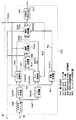
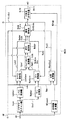
図19は上記ランレングス復号化器RLD2の具体的な構成を示すブロック図である。
上記ランレングス復号化器RLD2は、従来のランレングス復号化器RLD0cと同様、可変長復号化器VLDを有しており、この復号化器VLDは、上記実施の形態3の画像符号化装置103から出力された符号化ストリームStr2を復号化して、符号番号ExtCodeを出力するものである。
【0230】
そして、この実施の形態4では、ランレングス復号化器RLD2は、上記符号番号ExtCodeから、レベル値Lev1およびラン値Run1からなるランレベル上位桁対に対応する符号番号PrmCodeと、レベル値Lev2およびラン値Run2とを分離する番号逆変換処理を、上記量子化パラメータQPあるいはVLD選択信号VldSelに基づいて行う番号逆変換器ICodeTransと、処理対象ブロックに対応する複数の符号番号PrmCodeを、低い周波数のランレベル対に対応するものから順に並べ替えて、並べ替えられた順序を有する、該ブロックに対応する複数の符号番号Codeを出力する順序逆並替器IReOdrとを有している。
【0231】
さらに、上記ランレングス復号化器RLD2は、符号表もしくは算術計算によって、符号番号Codeに対応するランレベル対を取得して、該ランレベル対を構成するレベル値Lev1およびラン値Run1を出力するランレベル取得器RunLevDecと、ラン値Runの上位の桁を表すラン値Run1と、該ラン値Runの下位の桁を表すラン値Run2値とから、ラン値Runを復元するラン逆変換器IRunConvと、レベル値Levの上位の桁を表すレベル値Lev1と、レベル値Levの下位の桁を表すレベル値Lev2とから、レベル値Levを復元するレベル逆変換器ILevConvとを有している。
【0232】
また、上記ランレングス復号化器RLD2は、従来のランレングス復号化器RLD0cと同様、逆ジグザグスキャン器IScanを有しており、このスキャン器IScanは、レベル値LevとランRun値で表現される1次元配列を有する量子化成分を、2次元の配列を有する復号量子化成分DQSに変換して出力するものである。
なお、上記ランレングス復号化器RLD2における、可変長復号化器VLD,ランレベル取得器RunLevDec,及び逆ジグザグスキャン器IScanは、図41に示す従来のランレングス復号化器RLD0cにおけるものと同一のものである。
【0233】
次に作用効果について説明する。
上記ランレングス復号化器RLD2では、可変長復号化器VLDは、可変長符号化器VLCとは逆の動作を行う。つまり、可変長復号化器VLDは、符号化ストリームStr2を復号化して、該ストリームを構成する符号語(ビット列)に対応する符号番号ExtCodeを出力する。番号逆変換器ICodeTransは、上記量子化パラメータQPあるいはVLD選択信号VldSelに基づいて、番号変換器CodeTransとは逆の動作を行って、符号番号ExtCodeから、レベル値Lev1およびラン値Run1からなるランレベル上位桁対に対応する符号番号PrmCodeと、レベル値Lev2およびラン値Run2とを分離する。
【0234】
順序逆並替器IReOdrは、上記量子化パラメータQPあるいはVLD選択信号VldSelに基づいて、順序並替器ReOdrとは逆の動作を行う。これにより、処理対象ブロックに対応する複数の符号番号PrmCodeを、低い周波数のランレベル対に対応するものから順に並べ替える処理が行われ、並べ替えられた順序を有する、該ブロックに対応する複数の符号番号Codeが出力される。ランレベル取得器RunLevDecは、符号表もしくは算術計算によって、符号番号Codeに対応するランレベル対を取得して、取得したランレベル対を構成するレベル値Lev1およびラン値Run1を出力する。
【0235】
ラン逆変換器IRunConvは、上記量子化パラメータQPあるいはVLD選択信号VldSelに基づいて、ラン変換器RunConvとは逆の動作を行い、ラン値Runの上位の桁を表すラン値Run1と、ラン値Runの下位の桁を表すラン値Run2とから、ラン値Runを復元する。また、レベル逆変換器ILevConvは、上記量子化パラメータQPあるいはVLD選択信号VldSelに基づいて、レベル変換器LevConvとは逆の動作を行い、レベル値Levの上位の桁を表すレベル値Lev1と、レベル値Levの下位の桁を表すレベル値Lev2とから、レベル値Levを復元する。
【0236】
ここで、上記番号逆変換器ICodeTrans,順序逆並替器IReOdr,ラン逆変換器IRunConv,及びレベル逆変換器ILevConvでは、上記量子化パラメータQPあるいはVLD選択信号VldSelにより、上記第1及び第2の符号表の選択が行われ、選択された符号表に基づいた動作が行われる。
【0237】
そして、逆ジグザグスキャン器IScanは、レベル値Levとラン値Runに基づいて上記ジグザグスキャン器Scanとは逆の動作を行い、レベル値LevとランRun値で表現される1次元配列を有する量子化成分を、2次元の配列を有する復号量子化成分DQSに変換して出力する。
【0238】
また、このランレングス復号化器RLD2では、外部からVLD選択信号VldSelが入力されると、VLD選択信号VldSelにより示される、画像の内容(画像の動き量の大きさ,動きの複雑さ,絵柄の細かさ)に応じた適切な符号表が選択される。
【0239】
また、上記実施の形態4では、量子化パラメータQPとVLD選択信号VldSelが、上記番号逆変換器ICodeTrans,順序逆並替器IReOdr,ラン逆変換器IRunConv,及びレベル逆変換器ILevConvに供給されるので、量子化パラメータQPに応じて符号表を切り替えたり、画像の特性、つまり画像の動き量の大きさ,動きの複雑さ,絵柄の細かさなどによって、適切な符号表を画像復号化装置の外部から選択したりすることができる。
【0240】
このように本実施の形態4では、画像信号の量子化係数を可変長符号化してなる符号化データを復号化する画像復号化装置104において、符号表を用いて、可変長符号を量子化係数に変換するランレングス復号化器RLD2を備え、該ランレングス復号化器RLD2では、第1の符号表に基づいて、処理対象データに対して最適化された第2の符号表を作成し、量子化パラメータQPあるいはVLD選択信号VldSelに基づいて、可変長符号の量子化係数への変換に用いる符号表として、第1及び第2の符号表のいずれかを選択するので、処理対象データに存在する情報の冗長性をより効果的に除去することができる可変長符号化処理に対応した復号化処理を良好に行うことができる。
【0241】
なお、本実施の形態4では、ランレングス復号化器RLD2として、図19に示すように、様々な圧縮率向上のための機器、つまり番号逆変換器ICodeTrans,順序逆並替器IReOdr,ラン逆変換器IRunConv,及びレベル逆変換器ILevConvを有するものを示したが、上記ランレングス復号化器RLD2は、圧縮率向上のための機器の一部のもののみを有するものであってもよい。この場合、ランレングス復号化器RLD2の実装は簡単なものとなる。
【0242】
また、上記実施の形態4では、第2の符号表は、第1の符号表を構成する、規則的に算術演算で生成可能な部分(regularly build VLC)、及び規則的に生成できない部分(table look up VLC)の両方の部分における、ランレベル対と符号番号との対応関係を変更したものとしているが、第1の符号表が、規則的に算術演算で生成可能な部分(regularly build VLC)と規則的に生成できない部分(table look up VLC)とを有するものである場合は、上記第2の符号表は、第1の符号表の一部である、演算が容易な規則的に算術演算で生成可能な部分のみを変換したものであってもよく、その場合は、ランレングス復号化器RLD2の実装がより簡単なものとなる。
【0243】
また、この実施の形態4では、量子化成分の符号化データの可変長復号化を、ランレベル対を用いて行うランレングス復号化器において、量子化成分の符号化データを、より高い周波数成分に対応するものから順に可変長復号化するものを示したが、ランレングス復号化器は、実施の形態2のように、対象ブロックの量子化成分に対応するラン値及びレベル値の符号化データを別々に可変長復号化するランレングス復号化器において、対象ブロックの量子化成分に対応するラン値及びレベル値の符号化データを、より高い周波数成分に対応するものから順に可変長復号化するものであってもよい。
【0244】
(実施の形態5)
図20は本発明の実施の形態5による画像符号化装置を説明するためのブロック図である。
この実施の形態5の画像符号化装置105は、図13に示す実施の形態3の画像符号化装置103におけるランレングス符号化器RLE2に代えて、該ランレングス符号化器RLE2と同様ランレベル対の符号化を行うとともに、非0成分の個数を符号化するランレングス符号化器RLE3を備えたものである。この実施の形態5の画像符号化装置105におけるその他の機器は、実施の形態3の画像符号化装置103におけるものと同一である。
【0245】
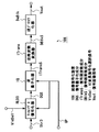
図21は上記画像符号化装置105におけるランレングス符号化器RLE3の具体的な構成を示している。
この実施の形態5のランレングス符号化器RLE3は、図14に示す実施の形態3のランレングス符号化器RLE2における位置計算器PosClcに代えて、入力される量子化成分に基づいて、非0係数の個数NZnumを計測する非0係数計測器NZcountと、該計測された非0係数の個数NZnum及びラン計測器RunCalにより計測されたラン値Runに基づいて、符号化済み係数の個数Pos2を計算する位置計算器PosClc2とを備えたものである。
【0246】
また、この実施の形態5のランレングス符号化器RLE3は、上記実施の形態3のランレングス符号化器RLE2の可変長符号化器VLCとは異なり、番号変換器CodeTransの出力(符号番号)ExtCodeを符号化するとともに、非0成分の個数NZnumを符号化するものである。
そして、該ランレングス符号化器RLE3におけるその他の構成は、実施の形態3のランレングス符号化器RLE2におけるものと同一である。
【0247】
次に作用効果について説明する。
この実施の形態5の画像符号化装置105のブロック化器Blk,周波数変換器Trans,量子化器Qの動作は、実施の形態3の画像符号化装置103におけるものと同一であり、また、この実施の形態5のランレングス符号化器RLE3の、非0係数計測器NZcount,位置計測器PosClc2,番号変換器CodeTrans,可変長符号化器VLC2以外の機器、つまりスキャン器Scan,ラン計測器RunCal,レベル計測器LevCal,ラン変換器RunConv,レベル変換器LevConv,ランレベルコード変換器RunLevEnc,順序並替器ReOdrの動作は、実施の形態3のランレングス符号化器RLE2のものと全く同一であるので、以下、主に、非0係数計測器NZcount,位置計測器PosClc2,番号変換器CodeTrans及び可変長符号化器VLC2の動作について説明する。
【0248】
量子化器Qから出力された量子化成分QSがランレングス符号化器RLE3に入力されると、ランレングス符号化器RLE3では、非0係数計測器NZcountは量子化成分QSに基づいて、各ブロックに対応する複数の量子化成分の中の非0成分の個数NZnumを計測し、該非0成分の個数NZnumを位置計算器PosClc2と可変長符号化器VLC2に出力する。
【0249】
位置計算器PosClc2は、上記非0係数計測器NZcountからの非0成分の個数NZnum、及びラン計測器RunCalからのラン値Runに基づいて、対象ブロックにおける符号化済0成分の個数と非0成分の個数の和を計算し、該計算値Pos2を出力する。
【0250】
番号変換器CodeTransは、上記ランレベル上位桁対と符号番号ReOdrCodeとの対応関係に基づいて、レベル値Lev2およびラン値Run2から、ランレベル対に対応する符号番号ExtCodeを出力する。このとき、番号変換器CodeTransでは、位置計算器PosClc2から出力された計算値Pos2が、対象ブロックにおける未符号化成分の個数を計算するために使用される。
【0251】
ここで、番号変換器CodeTransから出力される、ランレベル対に対応する符号番号ExtCodeは、ランレベル対と符号番号との対応関係が第1の符号表のものとは異なる第2の符号表に基づいて得られたものである。また、この第2の符号表は、上記順序並替器ReOdrでの並替え処理により、ランレベル対と符号番号の対応関係が第1の符号表とは異なる符号表を作成し、さらに、上記順序並替器ReOdrにて作成された符号表を、番号変換器CodeTransにて、上記計算値Pos2に基づいて、そのラン値が最大ラン値Runを超えるランレベル対を、符号を割り当てない符号番号ExtCodeに対応付けることにより、作成されたものである。
【0252】
そして、可変長符号化器VLC2は、非0成分の個数NZnumの符号化を行うとともに、該符号番号ExtCodeにビット列(符号語)を割り当てて符号化ストリームStr3を生成する、符号番号ExtCodeに対する符号化を行う。
【0253】
以下、可変長符号化器VLC2の動作について詳しく説明する。
この実施の形態5の可変長符号化器VLC2は、実施の形態3の可変長符号化器VLCとは異なり、対象ブロックのランレベル対に対応する符号番号ExtCodeを符号化するだけでなく、対象ブロックの非0成分の個数NZnumを該ブロックの符号番号ExtCodeの符号化以前に符号化する。
【0254】
このように非0成分の個数NZnumをブロックの符号番号ExtCodeの符号化以前に符号化すれば、復号化の際に対象ブロックの非0成分の個数NZnumを最初に復号化でき、非0成分の個数NZnum に相当する個数のランレベル対を復元した時点で、対象ブロックの最後のランレベル対の復元が完了したことを判別可能となる。この結果、実施の形態3の可変長符号化器VLCで必要であった対象ブロックの最後に符号化する特別の値EOB(最後の非0成分の後に伝送される値)が、可変長符号化器VLC2では不要となる。
【0255】
次に、位置計算器PosClc2及び番号変換器CodeTransの動作について詳しく説明する。
対象ブロックの量子化成分QSは、0成分および非0成分を合わせて、NBlock個存在するとすると、対象ブロックの非0係数の個数NZnumから、最大ラン長(0係数の最大連続数)はNBlock−NZnum個になる。また、最初のランレベル対の符号化が完了した時点での最大ラン値(0係数の最大連続数)MaxRun(1)は、対象ブロックの最初のランレベル対のラン値FRunを用いて以下の式(5)により表される。
MaxRun(1) = NBlock−NZnum−FRun・・・(5)
【0256】
一般には、ブロックにおけるi番目のランレベル対の符号化が完了した時点での最大ラン値MaxRun(i)は、下記の式(6)により表される。
MaxRun(i) = NBlock−NZnum
−{1番目から(i)番目までのラン値の和}・・・(6)
【0257】
従って、位置計算器PosClc2は、以下の(7)式で示す計算値Pos2を出力することで、番号変換器CodeTransに最大ラン値MaxRun(i)が(8)式で示される値であることを指示する。
Pos2 = NZnum+{1番目から(i)番目までのラン値の和}・・・(7)
MaxRun(i) = NBlock−Pos2 ・・・(8)
【0258】
番号変換器CodeTransは、第2の符号表を、そのラン値が最大ラン値MaxRunを超えるランレベル対には、符号を割り当てない符号番号ExtCodeを対応付けたものとする。これにより、発生するはずの無いランレベル対への符号の割り当てによる符号化処理の冗長を削減して、圧縮率を向上することができる。
【0259】
なお、上記量子化成分に対する可変長符号化処理を行う際、上記第1及び第2の符号表として、算術演算で生成可能な第1の部分(regularly build VLC)と、規則的な演算より生成できない第2の部分(table look up VLC)とから構成される可変長符号表を用いる場合は、第2の符号表は、第1の符号表に対して、該両部分を最大ラン値に応じて変更したものとしてもよいが、第2の符号表は、演算が容易な算術演算で生成可能な第1の部分のみを、第1の符号表に対して、最大ラン値に応じて変更したものとしても良い。
【0260】
また、i番目のランレベル対の符号化が完了した時点での最大ラン値MaxRun(i)に応じて、可変長符号表を変更する場合に、符号表を、ラン値Runが最大ラン値MaxRun(i)を超えるランレベル対に符号を割り当てないものとする代わりに、可変長符号表を直接、ラン値Runが最大ラン値MaxRun(i)を超えるランレベル対に符号が割り当てられていないものに切り替えるようにしても良い。
【0261】
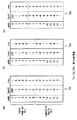
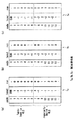
図24は可変長符号表の例を示す図である。符号表Ta(図24(a))は、符号表Tb(図24(b))に比べて、小さいラン値に割り当てられる符号をより短い符号としたものであり、該符号表Tb(図24(b))は、符号表Tc(図24(c))に比べて、小さいラン値に割り当てられる符号をより短い符号としたものである。
【0262】
また、符号表Tc(図24(c))は、符号表Tb(図24(b))に比べて、絶対値が小さいLevel値に割り当てられる符号をより短い符号としたものであり、符号表Tb(図24(b))は、符号表Ta(図24(a))に比べて、絶対値が小さいLevel値に割り当てられる符号をより短い符号としたものである。
【0263】
従って、最大ラン値MaxRunが小さい場合は図24(a)の符号表Ta、最大ラン値MaxRunが大きい場合は図24(c)の符号表Tc、最大ラン値MaxRunがその中間の値である場合は図24(b)の符号表Tbを選択して使用するのがよい。
【0264】
このように本実施の形態5では、画像信号の周波数成分を量子化して得られた量子化係数を符号化する画像符号化装置105において、上記量子化係数に符号表を用いて可変長符号を割り当てるランレングス符号化器RLE3を備え、該ランレングス符号化器RLE3では、符号化処理の対象ブロックにおける、符号化処理の施された処理済係数の個数と、該対象ブロックにおける、符号化処理の施されていない未符号化非0係数の個数との和、言いかえると、対象ブロックの非0係数の個数と対象ブロックの処理済みラン値の個数の和に応じて、出現する可能性のないランレベル対を排除した符号表を選択するので、可変長符号化効率を向上することができる効果がある。
【0265】
なお、上記実施の形態5では、ランレングス符号化器として、各ブロックの量子化成分に対する可変長符号化を、ランレベル対を用いて行う符号化器において、対象ブロックの非0成分の個数NZnumを符号化するものを示したが、ランレングス符号化器は、例えば、上記実施の形態1のように、各ブロックの量子化成分に対するラン値とレベル値を別々に可変長符号化する符号化器において、対象ブロックの非0成分の個数NZnumの符号化を行うものであってもよい。この場合、対象ブロックにおける最大ラン値を、対象ブロックにおけるすべての成分の個数から該非0成分の個数NZnumを減算したものとできる。
【0266】
(実施の形態6)
図22は、本発明の実施の形態6による画像復号化装置を説明するためのブロック図である。
この実施の形態6の画像復号化装置106は、図18に示す実施の形態4の画像復号化装置104におけるランレングス復号化器RLD2に代えて、符号化データの復号化処理により、各ブロック毎にランレベル対及び非0成分の個数を復元するランレングス復号化器RLD3を備えたものである。この実施の形態6の画像復号化装置106におけるその他の機器は、実施の形態4の画像復号化装置104におけるものと同一である。
【0267】
図23は上記画像復号化装置106におけるランレングス復号化器RLD3の具体的な構成を示している。
この実施の形態6のランレングス復号化器RLD3は、図19に示す実施の形態4のランレングス復号化器RLD2における位置計算機PosClcに代えて、復号化処理の対象ブロックにおける、復号化処理済みラン値の個数と、該対象ブロックにおける非0係数の個数NZnumとに基づいて、これらの個数の和Pos2を計算する位置計算機PosClc2を備えたものである。
【0268】
また、この実施の形態6のランレングス復号化器RLD3の可変長復号化器VLD2は、上記実施の形態4のランレングス復号化器RLD2の可変長符復号化器VLDとは異なり、符号番号ExtCodeを復元する復号化処理とともに、符号化された非0成分の個数NZnumを復元する復号化処理を行うものである。
【0269】
次に作用効果について説明する。
この実施の形態6の画像復号化装置106の逆量子化器IQ,逆周波数変換器ITrans,逆ブロック化器DeBlkの動作は、実施の形態4の画像復号化装置104におけるものと同一であり、また、この実施の形態6のランレングス復号化器RLD3の、可変長復号化器VLD2,位置計測器PosClc2,番号逆変換器ICodeTrans以外の機器、つまり順序逆並替器IReOdr,ランレベル取得器RunLevDec,レベル逆変換器ILevConv,ラン逆変換器IRunConv,逆ジグザグスキャン器IScanの動作は、実施の形態4のランレングス復号化器RLD2のものと全く同一であるので、以下、主に、可変長復号化器VLD2,位置計測器PosClc2,及び番号逆変換器ICodeTransの動作について説明する。
【0270】
可変長復号化器VLD2は、符号化ストリームStr3を復号化して、該ストリームを構成する符号語(ビット列)に対応する符号番号ExtCodeを出力する。番号逆変換器ICodeTransは、上記量子化パラメータQP及びVLD選択信号VldSelの少なくとも一方と、復号化済み係数個数と未復号化非0係数の個数の加算値Pos2とに基づいて、番号変換器CodeTransとは逆の動作を行って、符号番号ExtCodeから、レベル値Lev1およびラン値Run1からなるランレベル上位桁対に対応する符号番号PrmCodeと、レベル値Lev2およびラン値Run2とを分離する。
そして、順序逆並替器IReOdr、ランレベル取得器RunLevDec、ラン逆変換器IRunConv、レベル逆変換器ILevConv、逆ジグザグスキャン器IScanは、上記実施の形態4におけるものと同じ動作を行う。
【0271】
ここで、上記番号逆変換器ICodeTrans,順序逆並替器IReOdr,ラン逆変換器IRunConv,及びレベル逆変換器ILevConvでは、上記量子化パラメータQP及びVLD選択信号VldSelの少なくとも一方と、上記係数加算値Pos2に基づいて、上記第1及び第2の符号表の選択が行われ、選択された符号表に基づいた動作が行われる。
【0272】
以下、可変長復号化器VLD2の動作について詳しく説明する。
この実施の形態6の可変長復号化器VLD2は、実施の形態4の可変長復号化器VLDとは異なりランレベル対に対応する符号番号ExtCodeを復号化するだけでなく、対象ブロックの、符号化された非0成分の個数NZnumを復号化する。非0成分の個数NZnumを復号化により取得できれば、NZnum個のランレベル対を復号化した時点で、該NZnum個目のランレベル対が対象ブロックの最後のランレベル対であることが判別できる。この結果、可変長復号化器VLDで必要であった対象ブロックの最後に符号化する値EOBが、可変長復号化器VLD2では不要となる。
【0273】
例えば、対象ブロックの量子化成分QSは、0成分および非0成分を合わせてNBlock個存在するとすると、対象ブロックの非0係数の個数NZnum個から、最大ラン値(0係数の最大連続数)はNBlock−NZnum個になる。また、最初のランレベル対を復元する復号化が行われた時点での最大ラン値(0係数の最大連続数)MaxRun(1)は、実施の形態5で説明したように(NBlock−NZnum−FRun)個になる。
【0274】
一般には、ブロックにおけるi番目のランレベル対を復元する復号化が行われた時点での最大ラン値MaxRun(i)は、以下に示すように、
MaxRun(i)=NBlock−NZnum−{1番目から(i)番目までのラン値の和}
となる。
【0275】
従って、位置計算器PosClc2は、係数加算値Pos2〔=NZnum+{1番目から(i)番目までのラン値の和}〕を出力することで、番号変換器CodeTransに、i番目のランレベル対を復元する復号化が行われた時点での最大ラン値が(NBlock−Pos2)個であることを指示する。
【0276】
番号逆変換器ICodeTransでは、ラン値が最大ラン値Runを超えるランレベル対に対応する符号番号に符号が割り当てられていない符号表を用いて、符号に対応する符号番号ExtCodeを取得することにより、発生するはずの無いランレベル対への符号の割り当てを回避した符号割当により符号番号に割り当てられた符号を復号化できる。
【0277】
なお、上記可変長復号化処理を行う際、上記第1及び第2の符号表として、算術演算で生成可能な第1の部分(regularly build VLC)、及び規則的に生成できない第2の部分(table look up VLC)とにより構成される可変長符号表を用いる場合は、第2の符号表は、第1の符号表に対して、両部分を最大ラン値に応じて変更したものとしてもよいが、第2の符号表は、演算が容易な算術演算で生成可能な第1の部分のみを、第1の符号表に対して、最大ラン値に応じて変更したものとしてもよい。
【0278】
また、i番目のランレベル対を復元する復号化が完了した時点での最大ラン値MaxRunに応じて、可変長符号表を変更する場合に、符号表を、ラン値が最大ラン値MaxRunを超えるランレベル対に符号を割り当てないものとする代わりに、可変長符号表を、例えば、図24(a)に示す符号表Ta,図24(b)に示す符号表Tb,あるいは図24(c)に示す符号表Tcに直接切替えててもよい。
【0279】
例えば、最大ラン値MaxRunが小さい場合は図24(a)の符号表Ta、最大ラン値MaxRunが大きい場合は図24(c)の符号表Tc、最大ラン値MaxRunがその中間の値である場合は図24(b)の符号表Tbを選択して使用するのがよい。
【0280】
このように本実施の形態6では、符号化データの復号化処理により、画像信号の周波数成分を量子化して得られた量子化係数を復元する画像復号化装置106において、可変長符号に対応する量子化係数を、符号表を用いて取得するランレングス復号化器RLD3を備え、該ランレングス復号化器RLD3では、対象ブロックにおける、復号化処理の施された処理済係数の個数と、該対象ブロックにおける、復号化処理の施されていない未復号化非0係数の個数との和に応じて、出現する可能性のないランレベル対を排除した符号表を選択するので、処理対象となる量子化係数に存在する冗長性な情報をより効果的に除去することができる可変長符号化処理に対応した復号化処理を良好に行うことができる。
【0281】
なお、上記実施の形態6では、ランレングス復号化器として、各ブロックの量子化成分に対する可変長復号化を、ランレベル対を用いて行う復号化器において、対象ブロックの、符号化されている非0成分の個数NZnumを復号化するものを示したが、ランレングス復号化器は、例えば、上記実施の形態2のように、各ブロックの量子化成分に対応するラン値とレベル値とを別々に可変長復号化するランレングス復号化器において、対象ブロックの、符号化されている非0成分の個数NZnumを復号化するものであってもよい。この場合、NZnum個のレベル値を復号化した時点で、該NZnum個目のレベル値が対象ブロックの最後のレベル値であることを判別できる。
【0282】
また、上記各実施の形態では、量子化パラメータQPで符号表を切り替える例を説明したが、量子化パラメータQPでなく、他のパラメータでもよい。例えば、新たなパラメータを導入し、ブロック毎に明示的に切り替えてもよい。
【0283】
また、上記各実施の形態では、量子化成分などの係数を可変長符号化(復号化)する方法として、VLCテーブルを用いる方法であって、上記符号化(復号化)処理が施された処理済係数に関する情報、及び上記係数の生成に関するパラメータの少なくとも一方に応じて、VLCテーブルを切り替えるものを示したが、本発明の量子化成分などの係数の可変長符号化(復号化)方法は、VLCテーブルを用いるものに限るものではない。例えば、実施の形態1,3,5の、量子化成分を可変長符号化する方法は、上記VLCテーブルを用いない可変長符号化方法であって、上記処理済係数に関する情報、及び上記係数の生成に関するパラメータの少なくとも一方に応じて、上記VLCテーブルに相当する符号表を切り替えるものとしてもよい。また、実施の形態2,4,6の、量子化成分の符号化データを可変長復号化する方法は、上記VLCテーブルを用いない可変長復号化方法であって、上記処理済係数に関する情報、及び上記係数の生成に関するパラメータの少なくとも一方に応じて、上記VLCテーブルに相当する符号表を切り替えるものとしてもよい。
【0284】
また、上記各実施の形態では、可変長符号化処理を行う画像符号化装置あるいは可変長復号化処理を行う画像復号化装置を、ハードウエアにより実現したものを示したが、これらの装置はソフトウエアにより実現してもよい。この場合、上記各実施の形態で示した可変長符号化処理あるいは可変長復号化処理を行うためのプログラムをフレキシブルディスク等のデータ記憶媒体に記録しておくことにより、上記画像符号化装置あるいは画像復号化装置を、独立したコンピュータシステムにおいて簡単に実現することが可能となる。
【0285】
図25は、上記実施の形態1,3、5の可変長符号化処理または実施の形態2,4,6の可変長復号化処理を行うコンピュータシステムを説明するための図である。
【0286】
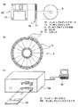
図25(a) は、コンピュータシステムにて用いるプログラムの記憶媒体であるフレキシブルディスクの、正面からみた外観、断面構造、及びフレキシブルディスク本体を示し、図25(b) は、フレキシブルディスク本体の物理フォーマットの例を示している。フレキシブルディスクFDは、上記ディスク本体DをケースF内に内蔵したものであり、該ディスク本体Dの表面には、同心円状に外周から内周に向かって複数のトラックTrが形成され、各トラックは角度方向に16のセクタSeに分割されている。従って、上記プログラムを格納したフレキシブルディスクFDでは、上記ディスク本体D上に割り当てられた記憶領域に、上記可変長符号化処理または可変長復号化処理を行うためのプログラムが記録されている。
【0287】
また、図25(c) は、フレキシブルディスクFDに上記プログラムの記録再生を行うための構成を示す。上記プログラムをフレキシブルディスクFDに記録する場合は、コンピュータシステムCsから上記プログラムをフレキシブルディスクドライブを介してフレキシブルディスクFDに書き込む。また、フレキシブルディスクFD内に記録されているプログラムにより上記画像符号化装置または画像復号化装置をコンピュータシステム中に構築する場合は、フレキシブルディスクドライブによりプログラムをフレキシブルディスクから読み出し、コンピュータシステムに転送する。
【0288】
なお、上記説明では、可変長符号化処理あるいは可変長復号化処理を行うためのプログラムを記録する記録媒体としてフレキシブルディスクを示したが、この記録媒体には光ディスクを用いても、上記フレキシブルディスクを用いる場合と同様に、ソフトウェアによる可変長符号化処理あるいは可変長復号化処理を行うことができる。また、上記記録媒体はこれらに限らず、CD-ROM、メモリカード、ROMカセット等、プログラムを記録できるものであればどのようなものでもよく、これらの記録媒体を用いる場合でも、上記フレキシブルディスク等を用いる場合と同様に、コンピュータシステムにより可変長符号化処理あるいは可変長復号化処理を行うことができる。
【0289】
さらに以下、上記実施の形態で示した画像符号化方法や画像復号化方法の応用例とそれを用いたシステムについて説明する。
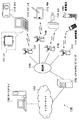
図26は、コンテンツ配信サービスを実現するコンテンツ供給システム1100の全体構成を示すブロック図である。
通信サービスの提供エリアは所望の大きさの領域(セル)に分割され、各セル内にそれぞれ固定無線局である基地局1107〜1110が設置されている。
【0290】
このコンテンツ供給システム1100では、例えば、インターネット1101にインターネットサービスプロバイダ1102,電話網1104,および基地局1107〜1110を介して、コンピュータ1111、PDA(personal digital assistant)1112、カメラ1113、携帯電話1114、カメラ付きの携帯電話1200などの各機器が接続されている。
【0291】
但し、コンテンツ供給システム1100は、図26に示す複数の機器をすべて含むものに限定されず、図26に示す複数の機器の一部のものを含むものであってもよい。また、各機器は、固定無線局である基地局1107〜1110を介さずに、電話網1104に直接接続されていてもよい。
【0292】
ここで、カメラ1113はデジタルビデオカメラ等の動画撮影が可能な機器である。また、携帯電話は、PDC(Personal Digital Communications)方式、CDMA(Code Division Multiple Access)方式、W−CDMA(Wideband-Code Division Multiple Access)方式、若しくはGSM(Global System for Mobile Communications)方式の携帯電話機、またはPHS(Personal Handyphone System)等であり、いずれの方式のものでもよい。
【0293】
また、ストリーミングサーバ1103は、カメラ1113とは基地局1109、電話網1104を介して接続されており、このシステムでは、カメラ1113を用いてユーザが送信する符号化処理されたデータに基づいたライブ配信等が可能となっている。撮影したデータの符号化処理はカメラ1113で行っても、データの送信処理をするサーバ等で行ってもよい。また、カメラ1116で動画像を撮影して得られた動画データはコンピュータ1111を介してストリーミングサーバ1103に送信されてもよい。カメラ1116はデジタルカメラ等の静止画、動画が撮影可能な機器である。この場合、動画データの符号化はカメラ1116で行ってもコンピュータ1111で行ってもどちらでもよい。また、符号化処理はコンピュータ1111やカメラ1116が有するLSI1117にて行われることになる。
【0294】
なお、画像符号化・復号化用のソフトウェアは、コンピュータ1111等で読み取り可能な記録媒体である蓄積メディア(CD−ROM、フレキシブルディスク、ハードディスクなど)に格納するようにしてもよい。さらに、動画データは、カメラ付きの携帯電話1200により送信してもよい。この動画データは携帯電話1200が有するLSIで符号化処理されたデータである。
【0295】
このコンテンツ供給システム1100では、ユーザがカメラ1113、カメラ1116等で撮影しているコンテンツ(例えば、音楽ライブを撮影した映像等)は、カメラから上記実施の形態同様に符号化処理してストリーミングサーバ1103に送信され、一方で、ストリーミングサーバ1103からは、要求のあったクライアントに対して上記コンテンツデータがストリーム配信される。
【0296】
クライアントとしては、上記符号化処理されたデータを復号化することが可能な、コンピュータ1111、PDA1112、カメラ1113、携帯電話1114等がある。
【0297】
このようなコンテンツ供給システム1100では、符号化されたデータをクライアント側にて受信して再生することができ、さらにクライアント側にてリアルタイムで受信して復号化し、再生することにより、個人放送をも実現可能である。
【0298】
このシステムを構成する各機器の符号化、復号化には上記各実施の形態で示した画像符号化装置あるいは画像復号化装置を用いるようにすればよい。
【0299】
その一例として携帯電話について説明する。
図27は、上記実施の形態で説明した画像符号化方法と画像復号化方法を用いた携帯電話1200を示す図である。
この携帯電話1200は、基地局1110との間で電波を送受信するためのアンテナ1201と、CCDカメラ等の映像,静止画を撮影可能なカメラ部1203と、カメラ部1203で撮影した映像、アンテナ1201で受信した映像等のデータを表示する液晶ディスプレイ等の表示部1202とを有している。
【0300】
また、携帯電話1200は、複数の操作キーが取り付けられている本体部1204と、音声出力を行うためのスピーカ等の音声出力部1208と、音声入力を行うためのマイク等の音声入力部1205と、撮影した動画もしくは静止画のデータ、受信したメールのデータ、動画のデータもしくは静止画のデータ等、符号化されたデータまたは復号化されたデータを保存するための記録メディア1207と、携帯電話1200に記録メディア1207を装着可能とするためのスロット部1206を有している。
【0301】
ここで、記録メディア1207はSDカード等のプラスチックケース内に電気的に書換えや消去が可能な不揮発性メモリであるEEPROM(Electrically Erasable and Programmable Read Only Memory)の一種であるフラッシュメモリ素子を格納したものである。
【0302】
さらに、携帯電話1200について図28を用いて詳細に説明する。
携帯電話1200は、表示部1202及び操作キー1204を備えた本体部の各部を統括的に制御する主制御部1241を有している。
また携帯電話1200は、電源回路部1240、操作入力制御部1234、画像符号化部1242、カメラインターフェース部1233、LCD(Liquid Crystal Display)制御部1232、画像復号化部1239、多重分離部1238、記録再生部1237、変復調回路部1236及び音声処理部1235を有している。携帯電話1200の各部は、同期バス1250を介して互いに接続されている。
【0303】
電源回路部1240は、ユーザの操作により、終話及び電源キーがオン状態にされると、バッテリパックの電力を各部に対して供給することによりカメラ付ディジタル携帯電話1200を動作可能な状態に起動する。
【0304】
携帯電話1200では、CPU、ROM及びRAM等でなる主制御部1241の制御により各部の動作が行われる。つまり、携帯電話1200では、音声通話モード時に音声入力部1205への音声入力により得られた音声信号は音声処理部1235によってディジタル音声データに変換される。ディジタル音声データは変復調回路部1236でスペクトラム拡散処理が施され、さらに、送受信回路部1231でディジタルアナログ変換処理及び周波数変換処理が施され、アンテナ1201を介して送信される。
【0305】
また携帯電話機1200では、音声通話モード時にアンテナ1201で受信された受信信号は増幅されて周波数変換処理及びアナログディジタル変換処理が施される。受信信号はさらに、変復調回路部1236でスペクトラム逆拡散処理が施され、音声処理部1235によってアナログ音声信号に変換され、この信号が音声出力部1208を介して出力される。
【0306】
さらに、携帯電話1200では、データ通信モード時に電子メールを送信する場合、本体部の操作キー1204の操作によって入力された電子メールのテキストデータは、操作入力制御部1234を介して主制御部1241に送出される。主制御部1241は、テキストデータを変復調回路部1236でスペクトラム拡散処理が施され、送受信回路部1231でディジタルアナログ変換処理及び周波数変換処理が施された後にアンテナ1201を介して基地局1110へ送信されるよう、各部を制御する。
【0307】
携帯電話1200では、データ通信モード時に画像データを送信する場合、カメラ部1203で撮像された画像データはカメラインターフェース部1233を介して画像符号化部1242に供給される。また、携帯電話1200では、画像データを送信しない場合には、カメラ部1203での撮像により得られた画像データをカメラインターフェース部1233及びLCD制御部1232を介して表示部1202に直接表示することも可能である。
【0308】
画像符号化部1242は、上記各実施の形態で説明した画像符号化装置を備えたものである。この画像符号化部1242は、カメラ部1203から供給された画像データを上記実施の形態の画像符号化方法によって圧縮符号化することにより符号化画像データに変換して、多重分離部1238に送出する。また、このとき同時に携帯電話機1200は、カメラ部1203で撮像中に音声入力部1205に入力された音声を音声処理部1235を介してディジタルの音声データとして多重分離部1238に送出する。
【0309】
多重分離部1238は、画像符号化部1242から供給された符号化画像データと音声処理部1235から供給された音声データとを所定の方式で多重化する。その結果得られる多重化データは変復調回路部1236でスペクトラム拡散処理が施され、さらに送受信回路部1231でディジタルアナログ変換処理及び周波数変換処理が施され、アンテナ1201を介して送信される。
【0310】
また、携帯電話1200では、データ通信モード時にホームページ等にリンクされた動画像ファイルのデータを受信する場合、アンテナ1201を介して基地局1110から受信した受信信号は、変復調回路部1236でスペクトラム逆拡散処理が施され、その結果得られた多重化データが多重分離部1238に送出される。
【0311】
また、アンテナ1201を介して受信された多重化データを復号化する際、多重分離部1238は、多重化データを分離することにより画像データの符号化ビットストリームと音声データの符号化ビットストリームとに分け、同期バス1250を介して該符号化画像データを画像復号化部1239に供給すると共に該音声データを音声処理部1235に供給する。
【0312】
次に、画像復号化部1239は、本発明の実施の形態による画像復号化装置を備えたものである。画像復号化部1239は、画像データの符号化ビットストリームを、上述した本発明の実施の形態の符号化方法に対応した復号化方法で復号することにより再生動画像データを生成し、これをLCD制御部1232を介して表示部1202に供給する。これにより、例えばホームページにリンクされた動画像ファイルに含まれる動画データの表示が行われる。このとき同時に音声処理部1235は、音声データをアナログ音声信号に変換した後、これを音声出力部1208に供給する。これにより、例えばホームページにリンクされた動画像ファイルに含まる音声データの再生が行われる。
【0313】
なお、上述した本発明の各実施の形態の画像符号化方法及び画像復号化方法を適用可能なシステムは、上記コンテンツ供給システムの例に限られるものではない。
【0314】
例えば、最近は衛星、地上波によるディジタル放送が話題となっており、上記実施の形態の画像符号化装置または画像復号化装置は、図29に示すようにディジタル放送用システムにも適用可能である。
【0315】
具体的には、放送局1409からは映像情報の符号化ビットストリームが無線通信により、通信衛星または放送衛星などの衛星1410に伝送される。放送衛星1410では、上記映像情報の符号化ビットストリームを受けると、放送用の電波が出力され、この電波が衛星放送受信設備をもつ家庭のアンテナ1406で受信される。例えば、テレビ(受信機)1401またはセットトップボックス(STB)1407などの装置では、符号化ビットストリームが復号化され、映像情報が再生される。
【0316】
また、記録媒体であるCDやDVD等の蓄積メディア1402に記録した符号化ビットストリームを読み取り、復号化する再生装置1403にも、上記実施の形態で示した画像復号化装置を実装することが可能である。
この場合、再生された映像信号はモニタ1404に表示される。また、ケーブルテレビ用のケーブル1405または衛星/地上波放送のアンテナ1406に接続されたセットトップボックス1407内に画像復号化装置を実装し、該画像復号化装置の出力をテレビのモニタ1408で再生する構成も考えられる。この場合、画像復号化装置は、セットトップボックスではなく、テレビ内に組み込んでもよい。また、アンテナ1411を有する車両1412では、衛星1410または基地局1107等から信号を受信し、車両1412に搭載されているカーナビゲーション1413等の表示装置に動画を再生することも可能である。
【0317】
更に、画像信号を上記実施の形態で示した画像符号化装置で符号化し、記録媒体に記録することもできる。
具体例な記録装置には、DVDディスク1421に画像信号を記録するDVDレコーダや、ハードディスクに画像信号を記録するディスクレコーダなどのレコーダ1420がある。更に画像信号は、SDカード1422に記録することもできる。また、レコーダ1420が上記実施の形態で示した画像復号化装置を備えていれば、レコーダ1420により、DVDディスク1421やSDカード1422に記録した画像信号を再生し、モニタ1408で表示することができる。
【0318】
なお、カーナビゲーション1413の構成としては、例えば図28に示す携帯電話の構成のうち、カメラ部1203,カメラインターフェース部1233,画像符号化部1242以外の部分を有するものが考えられ、同様なことがコンピュータ1111やテレビ(受信機)1401等については考えられる。
【0319】
また、上記携帯電話1114等の端末には、符号化器・復号化器を両方持つ送受信型端末の他に、符号化器のみを有する送信端末、復号化器のみ有する受信端末の3通りの実装形式が考えられる。
【0320】
このように、上記実施の形態で示した画像符号化方法あるいは画像復号化方法を上述したいずれの機器・システムにも用いることが可能であり、そうすることで、上記実施の形態で説明した効果を得ることができる。
さらには、本発明の各実施の形態及びその応用例は、本明細書で示したものに限られるものではないことは、言うまでもない。
【0321】
【発明の効果】
以上のように本発明に係る可変長符号化方法によれば、複数の係数からなる係数データを符号化する可変長符号化方法であって、上記各係数に対して、該係数の大きさを表す数値情報と符号との対応を示す複数の符号表を用いて、上記係数データを複数の符号からなる符号化データに変換する符号化処理を施す符号化ステップを含み、該符号化ステップは、上記符号表を、上記符号化処理が施された処理済係数に関する情報、及び上記係数の生成に関するパラメータの少なくとも一方に応じて選択する符号表選択ステップと、上記符号化処理が施されていない未符号化係数に対して、上記選択された符号表を用いて符号を割り当てる符号割当ステップとを含むものであることを特徴とするので、可変長符号化処理の対象となる係数データに含まれる冗長な情報が、該係数データを構成する係数の特性や該係数に対する符号化処理の状況に応じた符号表の選択により効果的に除去されることとなり、これにより画像信号などに対する可変長符号化処理の符号化効率を大きく向上することができる効果がある。
【0322】
本発明によれば、上記可変長符号化方法において、上記係数は、画像データの周波数成分を、該画像データに応じた量子化ステップに基づいて量子化して得られたものであり、上記符号表選択ステップは、上記符号割当ステップで用いる符号表を、上記量子化ステップの大きさに応じて選択するものであることを特徴とするので、常に、量子化ステップの大きさに適した、符号化効率が最大となる符号表を用いることができる効果がある。
【0323】
本発明によれば、上記可変長符号化方法において、上記係数に対する符号化処理は、その値が0である連続する0係数の個数を示すラン値と、該0係数に続く非0係数の値を示すレベル値とを、それぞれ符号に変換するものであり、上記符号表選択ステップは、上記ラン値と符号との対応を示す複数の符号表から、上記量子化ステップの大きさに応じて1つの符号表を選択する第1の選択処理と、上記レベル値と符号との対応を示す複数の符号表から、上記量子化ステップの大きさに応じて1つの符号表を選択する第2の選択処理のうちの少なくとも一方の選択処理を行うものであり、上記符号割当ステップは、上記選択された符号表に基づいて、上記符号化処理が施されていない未符号化係数に対応するラン値及びレベル値の少なくとも一方に符号を割り当てるものであることを特徴とするので、ラン値及びレベル値の少なくとも一方に対する符号の割当を、常に、量子化ステップの大きさに適した、割り当てられる符号の合計ビット数が最小となる符号表を用いて行うことができる効果がある。
【0324】
本発明によれば、上記可変長符号化方法において、上記係数に対する符号化処理は、その値が0である連続する0係数の個数を示すラン値と、該0係数に続く非0係数の値を示すレベル値とからなるランレベル対を符号に変換するものであり、上記符号表選択ステップは、上記量子化ステップの大きさに応じて、上記ランレベル対と符号との対応を示す複数の符号表から1つの符号表を選択するものであり、上記符号割当ステップは、上記選択された符号表に基づいて、上記符号化処理が施されていない未符号化係数に対応するランレベル対に符号を割り当てるものであることを特徴とするので、ランレベル対に対する符号の割当を、常に、量子化ステップの大きさに適した、割り当てられる符号の合計ビット数が最小となる符号表を用いて行うことができる効果がある。
【0325】
本発明によれば、上記可変長符号化方法において、上記符号表選択ステップは、上記符号割当ステップで用いる符号表を、上記符号化処理が施された処理済係数に関する情報に応じて選択するものであることを特徴とするので、量子化係数に対する符号化処理を、常に、未符号化係数の個数に適した、符号化効率が最大となる符号表を用いて行うことができる効果がある。
【0326】
本発明によれば、上記可変長符号化方法において、上記係数に対する符号化処理は、その値が0である連続する0係数の個数を示すラン値と、該0係数に続く非0係数の値を示すレベル値とを、それぞれ符号に変換するものであり、上記符号表選択ステップは、上記ラン値と符号との対応を示す複数の符号表から、符号化処理が施された処理済み係数に対応するラン値に関する情報に応じて1つの符号表を選択する第1の選択処理と、上記レベル値と符号との対応を示す複数の符号表から、符号化処理が施された処理済み係数に対応するレベル値に関する情報に応じて1つの符号表を選択する第2の選択処理のうちの少なくとも一方の選択処理を行うものであり、上記符号割当ステップは、上記選択された符号表に基づいて、上記符号化処理が施されていない未符号化係数に対応するラン値及びレベル値の少なくとも一方に符号を割り当てるものであることを特徴とするので、ラン値及びレベル値の少なくとも一方に対する符号の割当を、常に、未符号化係数の個数に適した、符号化効率が最大となる符号表を用いて行うことができる効果がある。
【0327】
本発明によれば、上記可変長符号化方法において、上記符号表選択ステップは、上記ラン値と符号との対応を示す複数の符号表から、符号が割当てられている処理済みラン値の個数に応じて1つの符号表を選択するものであり、上記符号割当ステップは、上記選択された符号表に基づいて、上記符号の割り当てられていない未符号化ラン値に符号を割り当てるものであることを特徴とするので、ラン値に対する符号の割当を、常に、未符号化ラン値の個数に適した、符号化効率が最大となる符号表を用いて行うことができる効果がある。
【0328】
本発明によれば、上記可変長符号化方法において、上記係数に対する符号化処理は、その値が0である連続する0係数の個数を示すラン値と、該0係数に続く非0係数の値を示すレベル値とからなるランレベル対を符号に変換するものであり、上記符号表選択ステップは、符号化処理が施された処理済み係数に対応するランレベル対に関する情報に応じて、上記ランレベル対と符号との対応を示す複数の符号表から1つの符号表を選択するものであり、上記符号割当ステップは、上記選択された符号表に基づいて、上記符号化処理が施されていない未符号化係数に対応するランレベル対に符号を割り当てるものであることを特徴とするので、ランレベル対に対する符号の割当を、常に、未符号化係数の個数に適した、符号化効率が最大となる符号表を用いて行うことができる効果がある。
【0329】
本発明によれば、上記可変長符号化方法において、上記係数は、画像データの周波数成分を、該画像データに応じた量子化ステップに基づいて量子化して得られたものであり、上記符号化ステップは、上記係数に対する符号化処理を、上記係数データを構成する複数の係数に対して、対応する画像データの周波数成分の高い順に符号が割当られるよう行うものであることを特徴とするので、上記係数に割り当てられる符号の合計ビット数をより一層削減することができる効果がある。
【0330】
本発明によれば、上記可変長符号化方法において、上記係数に対する符号化処理は、一定数の係数からなるブロック毎に、その値が0である連続する0係数の個数を示すラン値と、該0係数に続く非0係数の値を示すレベル値とからなるランレベル対を符号に変換するものであり、上記符号表選択ステップは、上記符号化処理の対象となる対象ブロックにおける、符号化処理の施された処理済係数の個数と、該対象ブロックにおける、符号化処理の施されていない未符号化非0係数の個数との和に応じて、上記ランレベル対と符号との対応を示す複数の符号表から1つの符号表を選択するものであり、上記符号割当ステップは、上記選択された符号表に基づいて、上記対象ブロックにおける未符号化係数に対応するランレベル対に符号を割り当てるものであることを特徴とするので、出現する可能性のないラン値とレベル値の対を排除した符号表を用いることができ、これにより可変長符号化効率を向上することができる効果がある。
【0331】
本発明によれば、上記可変長符号化方法において、上記係数に対する符号化処理は、その値が0である連続する0係数の個数を示すラン値と、該0係数に続く非0係数の値を示すレベル値とからなるランレベル対を符号に変換するものであり、上記符号化ステップは、上記ランレベル対と、これに対応する符号との対応を、該ランレベル対を形成するラン値とレベル値の組み合わせに応じて示す第1の符号表に基づいて、該第1の符号表における、ランレベル対と符号との対応を規則的に変更して、該第1の符号表とは、該ランレベル対と符号との対応が異なる第2の符号表を作成する符号表処理ステップを含み、上記符号表選択ステップは、上記第1及び第2の符号表の一方を、上記処理済係数に関する情報、及び上記係数の生成に関するパラメータの少なくとも一方に応じて選択するものであることを特徴とするので、ラン値とレベル値との対に符号を割り当てる際に用いる符号表として、第1及び第2の符号表のうちの最適なものが選択されることとなり、処理対象データに存在する情報の冗長性をより効果的に除去することができる。これにより画像信号などの圧縮率のさらなる向上を図ることができ、その実用的価値は高いものである。
【0332】
本発明によれば、上記可変長符号化方法において、上記第1及び第2の符号表は、各ランレベル対に、該ランレベル対を形成するレベル値が小さいほど、短い符号を対応付けたものであり、上記第2の符号表は、上記第1の符号表と比べて、平均的に、短い符号を対応付けられるランレベル対のレベル値が小さいものであることを特徴とするので、上記処理対象データを構成する係数の量子化パラメータが大きい場合に有効であるという効果がある。
【0333】
本発明によれば、上記可変長符号化方法において、上記第1及び第2の符号表は、各ランレベル対に、該ランレベル対を形成するラン値が小さいほど、短い符号を対応付けたものであり、上記第2の符号表は、上記第1の符号表と比べて、平均的に、短い符号を対応付けられるランレベル対のラン値が小さいものであることを特徴とするので、上記処理対象データを構成する係数の量子化パラメータが小さい場合に有効である。
【0334】
本発明によれば、上記可変長符号化方法において、上記係数に対する符号化処理は、ランレベル対の符号への変換を、一定数の係数からなるブロック毎に行うものであり、上記符号表処理ステップは、上記第2の符号表を、上記符号化処理の対象となる対象ブロックにおける、該符号化処理が施された処理済係数の数に応じて作成するものであることを特徴とするので、第2の符号表を、出現する可能性のないラン値とレベル値の対を排除したものとすることができ、これにより可変長符号化効率を一層向上することができる効果がある。
【0335】
本発明によれば、上記可変長符号化方法において、上記符号割当ステップは、上記ランレベル対に対する符号の割当を、画像データの周波数成分の高い係数に対応するランレベル対から順に行うものであることを特徴とするので、第2の符号表を、出現する可能性のないラン値とレベル値の対を排除したものとすることによる可変長符号化効率の向上を、より大きなものとすることができる効果がある。
【0336】
本発明によれば、上記可変長符号化方法において、上記第2の符号表は、上記第1の符号表に含まれる、ランレベル対と符号との複数の対応のうちの、規則的に算出可能な対応のみを変更したものであることを特徴とするので、第2の符号表の作成に要する演算処理を削減することができる効果がある。
【0337】
本発明によれば、上記可変長符号化方法において、上記係数データを構成する係数は、画像データの周波数成分を、画像データに応じた量子化ステップに基づいて量子化して得られたものであり、上記符号表選択ステップは、上記第1の符号表と第2の符号表の切替えを、上記量子化ステップの大きさに基づいて行う符号表切替ステップであることを特徴とするので、上記処理対象データを構成する係数の可変長符号化処理に用いる符号表として、量子化ステップに適したものを用いることができる効果がある。
【0338】
本発明によれば、上記可変長符号化方法において、上記符号表選択ステップは、上記第1の符号表と第2の符号表の切替を、切替え指示信号に基づいて行う符号表切替ステップであり、上記符号化ステップは、上記切替え指示信号の符号化処理を行うものであることを特徴とするので、処理対象データの特性などに合わせて、上記係数の可変長符号化処理に用いる符号表を切替えることができる効果がある。
【0339】
本発明によれば、上記可変長符号化方法において、上記係数に対する符号化処理は、ランレベル対の符号への変換を、一定の係数からなるブロック毎に行うものであり、上記符号表処理ステップは、上記第2の符号表を、符号化処理の対象となる対象ブロックにおける、符号化処理が施された処理済係数の個数と、該対象ブロックにおける、符号化処理が施されていない未符号化非0係数の個数との和に応じて作成するものであることを特徴とするので、第2の符号表を、出現する可能性のないラン値とレベル値の対を排除したものとすることができ、これにより可変長符号化効率を一層向上することができる効果がある。
【0340】
本発明に係る可変長符号化装置によれば、複数の係数からなる係数データを符号化する可変長符号化装置であって、上記各係数に対して、該係数の大きさを表す数値情報と符号との対応を示す複数の符号表を用いて、上記係数データを複数の符号からなる符号化データに変換する符号化処理を施す符号化部を含み、該符号化部は、上記符号表を、上記符号化処理が施された処理済係数に関する情報、及び上記係数の生成に関するパラメータの少なくとも一方に応じて選択する符号表選択部と、上記符号化処理が施されていない未符号化係数に対して、上記選択された符号表を用いて符号を割り当てる符号割当部とを有するものであることを特徴とするので、可変長符号化処理の対象となる係数データに含まれる冗長な情報が、該係数データを構成する係数の特性や該係数に対する符号化処理の状況に応じた符号表の選択により効果的に除去されることとなり、これにより画像信号などに対する可変長符号化処理の符号化効率を大きく向上することができる効果がある。
【0341】
本発明によれば、上記可変長符号化装置において、上記係数は、画像データの周波数成分を、該画像データに応じた量子化ステップに基づいて量子化して得られたものであり、上記符号表選択部は、上記符号割当部で用いる符号表を、上記量子化ステップの大きさに応じて選択するものであることを特徴とするので、常に、量子化ステップの大きさに適した、符号化効率が最大となる符号表を用いることができる効果がある。
【0342】
本発明によれば、上記可変長符号化装置において、上記符号表選択部は、上記符号割当部で用いる符号表を、上記符号化処理が施された処理済係数に関する情報に応じて選択するものであることを特徴とするので、量子化係数に対する符号化処理を、常に、未符号化係数の個数に適した、符号化効率が最大となる符号表を用いて行うことができる効果がある。
【0343】
本発明によれば、上記可変長符号化装置において、上記係数に対する符号化処理は、その値が0である連続する0係数の個数を示すラン値と、該0係数に続く非0係数の値を示すレベル値とを、それぞれ符号に変換するものであり、上記符号表選択部は、上記ラン値と符号との対応を示す複数の符号表から、符号が割当てられている処理済みラン値の個数に応じて1つの符号表を選択するものであり、上記符号割当部は、上記選択された符号表に基づいて、上記符号の割り当てられていない未符号化ラン値に符号を割り当てるものであることを特徴とするので、ラン値に対する符号の割当を、常に、未符号化ラン値の個数に適した、符号化効率が最大となる符号表を用いて行うことができる効果がある。
【0344】
本発明によれば、 上記可変長符号化装置において、上記係数は、画像データの周波数成分を、該画像データに応じた量子化ステップに基づいて量子化して得られたものであり、上記符号化部は、上記係数に対する符号化処理を、上記係数データを構成する複数の係数に対して、対応する画像データの周波数成分の高い順に符号が割当られるよう行うものであることを特徴とするので、上記係数に割り当てられる符号の合計ビット数をより一層削減することができる効果がある。
【0345】
本発明に係るプログラム記憶媒体によれば、複数の係数からなる係数データを符号化する可変長符号化処理をコンピュータにより行うプログラムを格納した記憶媒体であって、上記プログラムは、上記各係数に対して、該係数の大きさを表す数値情報と符号との対応を示す複数の符号表を用いて、上記係数データを複数の符号からなる符号化データに変換する符号化処理を施す符号化ステップを含み、該符号化ステップは、上記符号表を、上記符号化処理が施された処理済係数に関する情報、及び上記係数の生成に関するパラメータの少なくとも一方に応じて選択する符号表選択ステップと、上記符号化処理が施されていない未符号化係数に対して、上記選択された符号表を用いて符号を割り当てる符号割当ステップとを含むものであることを特徴とするので、可変長符号化処理の対象となる係数データに含まれる冗長な情報を、該係数データを構成する係数の特性や該係数に対する符号化処理の状況に応じた符号表の選択により効果的に除去できる符号化効率の高い可変長符号化処理を、ソフトウエアにより実現することができる効果がある。
【0346】
本発明に係る可変長復号化方法によれば、複数の係数からなる係数データを可変長符号化して得られた、複数の符号からなる符号化データを復号化する可変長復号化方法であって、上記各符号に対して、上記係数の大きさを表す数値情報と上記符号との対応を示す複数の符号表を用いて、上記符号化データを上記複数の係数からなる係数データに復元する復号化処理を施す復号化ステップを含み、該復号化ステップは、上記符号表を、上記符号化処理が施された処理済係数に関する情報、及び上記係数の生成に関するパラメータの少なくとも一方に応じて選択する符号表選択ステップと、上記復号化処理が施されていない未復号化符号に対応する数値情報を、上記選択された符号表を用いて取得する数値取得ステップとを含むものであることを特徴とするので、係数データを、符号表の切替えにより該係数データに含まれる冗長な情報を効果的に除去して符号化することができる符号化効率の高い可変長符号化処理に対応した可変長復号化処理を行うことができる効果がある。
【0347】
本発明によれば、上記可変長復号化方法において、上記係数は、画像データの周波数成分を、該画像データに応じた量子化ステップに基づいて量子化して得られたものであり、上記符号表選択ステップは、上記数値取得ステップで用いる符号表を、上記量子化ステップの大きさに応じて選択するものであることを特徴とするので、常に、量子化ステップの大きさに適した、符号化効率が最大となる符号表を用いる可変長符号化処理に対応した可変長復号化処理を行うことができる効果がある。
【0348】
本発明によれば、上記可変長復号化方法において、上記符号に対する復号化処理は、上記符号を、その値が0である連続する0係数の個数を示すラン値と、該0係数に続く非0係数の値を示すレベル値とに復元するものであり、上記符号表選択ステップは、上記ラン値と符号との対応を示す複数の符号表から、上記量子化ステップの大きさに応じて1つの符号表を選択する第1の選択処理と、上記レベル値と符号との対応を示す複数の符号表から、上記量子化ステップの大きさに応じて1つの符号表を選択する第2の選択処理のうちの少なくとも一方の選択処理を行うものであり、上記数値取得ステップは、上記選択された符号表に基づいて、上記復号化処理が施されていない未復号化符号に対応するラン値及びレベル値の少なくとも一方を取得するものであることを特徴とするので、ラン値及びレベル値の少なくとも一方に対する符号の割当を、常に、量子化ステップの大きさに適した、割り当てられる符号の合計ビット数が最小となる符号表を用いて行う可変長符号化処理に対応した可変長復号化処理を行うことができる効果がある。
【0349】
本発明によれば、上記可変長復号化方法において、上記符号に対する復号化処理は、該符号を、その値が0である連続する0係数の個数を示すラン値と、該0係数に続く非0係数の値を示すレベル値とからなるランレベル対に復元するものであり、上記符号表選択ステップは、上記量子化ステップの大きさに応じて、上記ランレベル対と符号との対応を示す複数の符号表から1つの符号表を選択するものであり、上記数値取得ステップは、上記選択された符号表に基づいて、上記復号化処理が施されていない未復号化符号に対応するランレベル対を取得するものであることを特徴とするので、ランレベル対に対する符号の割当を、常に、量子化ステップの大きさに適した、割り当てられる符号の合計ビット数が最小となる符号表を用いて行う可変長符号化処理に対応した可変長復号化処理を行うことができる効果がある。
【0350】
本発明によれば、上記可変長復号化方法において、上記符号表選択ステップは、上記数値取得ステップで用いる符号表を、上記復号化処理により得られた処理済係数に関する情報に応じて選択するものであることを特徴とするので、量子化係数を、常に、未復号化係数の個数に適した、符号化効率が最大となる符号表を用いて符号化する可変長符号化処理に対応した可変長復号化処理を行うことができる効果がある。
【0351】
本発明によれば、上記可変長復号化方法において、上記符号に対する復号化処理は、該符号を、その値が0である連続する0係数の個数を示すラン値と、該0係数に続く非0係数の値を示すレベル値とに復元するものであり、上記符号表選択ステップは、上記ラン値と符号との対応を示す複数の符号表から、復号化処理により得られた処理済みラン値に関する情報に応じて1つの符号表を選択する第1の選択処理と、上記レベル値と符号との対応を示す複数の符号表から、復号化処理により得られた処理済みレベル値に関する情報に応じて1つの符号表を選択する第2の選択処理のうちの少なくとも一方の選択処理を行うものであり、上記数値取得ステップは、上記選択された符号表に基づいて、上記復号化処理が施されていない未復号化符号に対応するラン値及びレベル値の少なくとも一方を取得するものであることを特徴とするので、ラン値及びレベル値の少なくとも一方に対する符号の割当を、常に、未復号化係数の個数に適した、符号化効率が最大となる符号表を用いて行う可変長符号化処理に対応した可変長復号化処理を行うことができる効果がある。
【0352】
本発明によれば、上記可変長復号化方法において、上記符号表選択ステップは、上記ラン値と符号との対応を示す複数の符号表から、復号化処理により得られた処理済みラン値の個数に応じて1つの符号表を選択するものであり、上記数値取得ステップは、上記選択された符号表に基づいて、上記復号化処理が施されていない未復号化符号に対応するラン値を取得するものであることを特徴とするので、ラン値に対する符号の割当を、常に、未復号化ラン値の個数に適した、符号化効率が最大となる符号表を用いて行う可変長符号化処理に対応した可変長復号化処理を行うことができる効果がある。
【0353】
本発明によれば、上記可変長復号化方法において、上記符号に対する復号化処理は、符号を、その値が0である連続する0係数の個数を示すラン値と、該0係数に続く非0係数の値を示すレベル値とからなるランレベル対に復元するものであり、上記符号表選択ステップは、復号化処理により得られたランレベル対に関する情報に応じて、上記ランレベル対と符号との対応を示す複数の符号表から1つの符号表を選択するものであり、上記数値取得ステップは、上記選択された符号表に基づいて、上記復号化処理が施されていない未復号化符号に対応するランレベル対を取得するものであることを特徴とするので、ランレベル対に対する符号の割当を、常に、未復号化係数の個数に適した、符号化効率が最大となる符号表を用いて行う可変長符号化処理に対応した可変長復号化処理を行うことができる効果がある。
【0354】
本発明によれば、上記可変長復号化方法において、上記係数は、画像データの周波数成分を、該画像データに応じた量子化ステップに基づいて量子化して得られたものであり、上記復号化ステップは、上記符号に対する復号化処理を、上記符号に対応する数値情報が、対応する画像データの周波数成分の高いものから順に取得されるよう行うものであることを特徴とするので、上記係数に割り当てられる符号の合計ビット数をより一層削減可能な可変長符号化処理に対応した可変長復号化処理を行うことができる効果がある。
【0355】
本発明によれば、上記可変長復号化方法において、上記符号に対する復号化処理は、上記係数データを構成する一定数の係数からなるブロック毎に、上記符号を、その値が0である連続する0係数の個数を示すラン値と、該0係数に続く非0係数の値を示すレベル値とからなるランレベル対に復元するものであり、上記符号表選択ステップは、上記復号化処理の対象となる対象ブロックにおける、該ブロックの復号化処理により得られた処理済係数の個数と、該対象ブロックにおける、該ブロックの復号化処理では未だ得られていない未復号化非0係数の個数との和に応じて、上記ランレベル対と符号との対応を示す複数の符号表から1つの符号表を選択するものであり、上記数値取得ステップは、上記選択された符号表に基づいて、上記対象ブロックにおける未復号化係数に対応するランレベル対を取得するものであることを特徴とするので、出現する可能性のないラン値とレベル値の対を排除した符号表を用いて、効率の高い可変長符号化処理に対応した可変長復号化処理を実現できる効果がある。
【0356】
本発明によれば、上記可変長復号化方法において、上記符号に対する復号化処理は、該符号化データを構成する符号を、その値が0である連続する0係数の個数を示すラン値と、該0係数に続く非0係数の値を示すレベル値とからなるランレベル対に復元するものであり、上記復号化ステップは、上記ランレベル対と、これに対応する符号との対応を、該ランレベル対を形成するラン値とレベル値の組み合わせに応じて示す第1の符号表に基づいて、該第1の符号表における、ランレベル対と符号との対応を規則的に変更して、該第1の符号表とは、該ランレベル対と符号との対応が異なる第2の符号表を作成する符号表処理ステップを含み、上記符号表選択ステップは、上記第1及び第2の符号表の一方を、上記処理済係数に関する情報、及び上記係数の生成に関するパラメータの少なくとも一方に応じて選択するものであることを特徴とするので、符号をラン値とレベル値との対に変換する際に用いる符号表として、第1及び第2の符号表のうちの最適なものが選択されることとなる。これにより、処理対象データに存在する情報の冗長性をより効果的に除去する可変長符号化処理に対応する可変長復号化処理を良好に行うことができ、その実用的価値は高いものである。
【0357】
本発明によれば、上記可変長復号化方法において、上記第1及び第2の符号表は、各ランレベル対に、該ランレベル対を形成するレベル値が小さいほど、短い符号を対応付けたものであり、上記第2の符号表は、上記第1の符号表と比べて、平均的に、短い符号を対応付けられるランレベル対のレベル値が小さいものであることを特徴とするので、上記処理対象データを構成する係数に関する量子化パラメータが大きい場合に有効である。
【0358】
本発明によれば、上記可変長復号化方法において、上記第1及び第2の符号表は、各ランレベル対に、該ランレベル対を形成するラン値が小さいほど、短い符号を対応付けたものであり、上記第2の符号表は、上記第1の符号表と比べて、平均的に、短い符号を対応付けられるランレベル対のラン値が小さいものであることを特徴とするので、上記処理対象データを構成する係数の量子化パラメータが小さい場合に有効である。
【0359】
本発明によれば、上記可変長復号化方法において、上記符号に対する復号化処理は、該符号のランレベル対への復元を、上記係数データを構成する一定数の係数からなるブロック毎に行うものであり、上記符号表処理ステップは、上記第2の符号表を、上記復号化処理の対象となる対象ブロックにおける、該復号化処理により得られた処理済係数の数に応じて作成するものであることを特徴とするので、第2の符号表を、出現する可能性のないラン値とレベル値の対を排除したものとすることができ、これにより、より効率の高い可変長符号化処理に対応した可変長復号化処理を実現できる効果がある。
【0360】
本発明によれば、上記可変長復号化方法において、上記数値取得ステップは、上記符号に対応するランレベル対の取得を、対応する画像データの周波数成分の高いランレベル対から順に行うものであることを特徴とするので、第2の符号表を、出現する可能性のないラン値とレベル値の対を排除したものとすることによりさらに効果的に圧縮率を向上した可変長符号化処理に対応する可変長復号化処理を実現できる効果がある。
【0361】
本発明によれば、上記可変長復号化方法において、上記第2の符号表は、上記第1の符号表に含まれる、ランレベル対と符号との複数の対応のうちの、規則的に算出可能な対応のみを変更したものであることを特徴とするので、第2の符号表の作成に要する演算処理を削減することができる効果がある。
【0362】
本発明によれば、上記可変長復号化方法において、上記係数データを構成する係数は、画像データの周波数成分を、画像データに応じた量子化ステップに基づいて量子化して得られたものであり、上記符号表選択ステップは、上記第1の符号表と第2の符号表の切替えを、上記量子化ステップの大きさに基づいて行うものであることを特徴とするので、上記処理対象データを構成する係数の可変長復号化処理に用いる符号表として、量子化ステップに適したものを用いることができる効果がある。
【0363】
本発明によれば、上記可変長復号化方法において、上記符号表選択ステップは、上記第1の符号表と第2の符号表の切替を、切替え指示信号に基づいて行う符号表切替ステップを含むものであり、上記復号化ステップは、上記切替え指示信号の復号化処理を行うものであることを特徴とするので、処理対象データの特性などに合わせて、可変長復号化処理に用いる符号表を切替えることができる効果がある。
【0364】
本発明によれば、上記可変長復号化方法において、上記符号に対する復号化処理は、符号のランレベル対への復元を、上記係数データを構成する一定の係数からなるブロック毎に行うものであり、上記符号表処理ステップは、上記第2の符号表を、復号化処理の対象となる対象ブロックにおける、該ブロックに対する復号化処理により得られた処理済係数の個数と、該対象ブロックにおける、該ブロックに対する復号化処理では未だ得られていない未復号化非0係数の個数との和に応じて作成するものであることを特徴とするので、第2の符号表として、出現する可能性のないラン値とレベル値の対を排除したものを用いて、より効率の高い可変長符号化処理に対応した可変長復号化処理を実現できる効果がある。
【0365】
本発明に係る可変長復号化装置によれば、複数の係数からなる係数データを可変長符号化して得られた、複数の符号からなる符号化データを復号化する可変長復号化装置であって、上記各符号に対して、上記係数の大きさを表す数値情報と上記符号との対応を示す複数の符号表を用いて、上記符号化データを上記複数の係数からなる係数データに復元する復号化処理を施す復号化部を備え、該復号化部は、上記符号表を、上記復号化処理が施された処理済係数に関する情報、及び上記係数の生成に関するパラメータの少なくとも一方に応じて選択する符号表選択部と、上記復号化処理が施されていない未復号化符号に対応する数値情報を、上記選択された符号表を用いて取得する数値取得部とを有するものであることを特徴とするので、係数データを、符号表の切替えにより該係数データの情報の冗長性を効果的に除去して符号化することができる符号化効率の高い可変長符号化処理に対応した可変長復号化処理を行うことができる効果がある。
【0366】
本発明によれば、上記可変長復号化装置において、上記係数は、画像データの周波数成分を、該画像データに応じた量子化ステップに基づいて量子化して得られたものであり、上記符号表選択部は、上記数値取得部で用いる符号表を、上記量子化ステップの大きさに応じて選択するものであることを特徴とするので、常に、量子化ステップの大きさに適した、符号化効率が最大となる符号表を用いる可変長符号化処理に対応した可変長復号化処理を行うことができる効果がある。
【0367】
本発明によれば、上記可変長復号化装置において、上記符号表選択部は、上記数値取得部で用いる符号表を、上記復号化処理により得られた処理済係数に関する情報に応じて選択するものであることを特徴とするので、量子化係数を、常に、未復号化係数の個数に適した、符号化効率が最大となる符号表を用いて符号化する可変長符号化処理に対応した可変長復号化処理を行うことができる効果がある。
【0368】
本発明によれば、上記可変長復号化装置において、上記符号に対する復号化処理は、該符号を、その値が0である連続する0係数の個数を示すラン値と、該0係数に続く非0係数の値を示すレベル値とに復元するものであり、上記符号表選択部は、上記ラン値と符号との対応を示す複数の符号表から、復号化処理により得られた処理済みラン値の個数に応じて1つの符号表を選択するものであり、上記数値取得部は、上記選択された符号表に基づいて、上記復号化処理が施されていない未復号化符号に対応するラン値を取得するものであることを特徴とするので、ラン値に対する符号の割当を、常に、未復号化ラン値の個数に適した、符号化効率が最大となる符号表を用いて行う可変長符号化処理に対応した可変長復号化処理を行うことができる効果がある。
【0369】
本発明によれば、上記可変長復号化装置において、上記係数は、画像データの周波数成分を、該画像データに応じた量子化ステップに基づいて量子化して得られたものであり、上記復号化部は、上記符号に対する復号化処理を、上記符号に対応する数値情報が、対応する画像データの周波数成分の高いものから順に取得されるよう行うものであることを特徴とするので、上記係数に割り当てられる符号の合計ビット数をより一層削減可能な可変長符号化処理に対応した可変長復号化処理を行うことができる効果がある。
【0370】
本発明に係るプログラム記憶媒体によれば、複数の係数からなる係数データを可変長符号化して得られた、複数の符号からなる符号化データを復号化する可変長復号化処理をコンピュータにより行うプログラムを格納した記憶媒体であって、上記プログラムは、上記各符号に対して、上記係数の大きさを表す数値情報と上記符号との対応を示す複数の符号表を用いて、上記符号化データを上記複数の係数からなる係数データに復元する復号化処理を施す復号化ステップを含み、該復号化ステップは、上記符号表を、上記符号化処理が施された処理済係数に関する情報、及び上記係数の生成に関するパラメータの少なくとも一方に応じて選択する符号表選択ステップと、上記復号化処理が施されていない未復号化符号に対応する数値情報を、上記選択された符号表を用いて取得する数値取得ステップとを含むものであることを特徴とするので、係数データを、符号表の切替えにより該係数データに含まれる冗長な情報を効果的に除去して符号化することができる符号化効率の高い可変長符号化処理に対応した可変長復号化処理を、ソフトウエアにより実現することができる効果がある。
【図面の簡単な説明】
【図1】 本発明の実施の形態1による画像符号化装置101を説明するためのブロック図である。
【図2】 上記実施の形態1の画像符号化装置101を構成するランレングス符号化器RLE1を示すブロック図である。
【図3】 上記ランレングス符号化器RLE1でのジグザグスキャン(図(a)〜図(d))及びラン値,レベル値の並べ替え(図(e),図(f))を説明するための図である。
【図4】 上記ランレングス符号化器RLE1の可変長符号化器LVLCでの処理を説明する図であり、図4(a)はレベル値の可変長符号化処理のフロー、図4(b)は該レベル値の可変長符号化処理で用いる符号表を示している。
【図5】 上記ランレングス符号化器RLE1の可変長符号化器RVLCでの処理を説明する図であり、ラン値の可変長符号化処理のフロー(図(a))、及び該ラン値の可変長符号化処理で用いる符号表(図(b))を示している。
【図6】 上記可変長符号化器LVLCにてレベル値(量子化パラメータ比較的小)に割り当てられる符号の合計ビット数を、符号表L2を用いた場合(図(a))と符号表L1を用いた場合(図(b))とに分けて示す図である。
【図7】 上記可変長符号化器LVLCにてレベル値(量子化パラメータ比較的大)に割り当てられる符号の合計ビット数を、符号表L2を用いた場合(図(a))と符号表L1を用いた場合(図(b))とに分けて示す図である。
【図8】 上記可変長符号化器RVLCにてラン値に割り当てられる符号の合計ビット数を、特定の符号表を用いた場合(図(a))、符号表の切替及びラン値の並替を行った場合(図(b))、符号表の切替のみ行った場合(図(c))に分けて示す図である。
【図9】 本発明の実施の形態2による画像復号化装置102を説明するためのブロック図である。
【図10】 上記実施の形態2の画像復号化装置102を構成するランレングス復号化器RLD1を示すブロック図である。
【図11】 上記可変長復号化器LVLDの可変長復号化処理を説明する図であり、レベル値を復元する可変長復号化処理のフロー(図(a))、及び該可変長復号化処理で用いる符号表(図(b))を示している。
【図12】 上記可変長復号化器RVLDの可変長復号化処理を説明する図であり、ラン値を復元する可変長復号化処理のフロー(図(a))、及び該可変長復号化処理で用いる符号表(図(b))を示している。
【図13】 本発明の実施の形態3による画像符号化装置103を説明するためのブロック図である。
【図14】 上記実施の形態3の画像符号化装置103を構成するランレングス符号化器RLE2を示すブロック図である。
【図15】 上記実施の形態3のランレングス符号化器RLE2にて作成される符号表(第2の符号表)の例T2a(図(a)),T2b(図(b))を示す図である。
【図16】 上記実施の形態3のランレングス符号化器RLE2にて作成される符号表(第2の符号表)のその他の例T2c(図(a)),T2d(図(b)),T2e(図(c))を示す図である。
【図17】 上記実施の形態3のランレングス符号化器RLE2における量子化成分の符号化順序の例を示す図である。
【図18】 本発明の実施の形態4による画像復号化装置104を説明するためのブロック図である。
【図19】 上記実施の形態4の画像復号化装置104を構成するランレングス復号化器RLD2を示すブロック図である。
【図20】 本発明の実施の形態5による画像符号化装置105を説明するためのブロック図である。
【図21】 上記実施の形態5の画像符号化装置105を構成するランレングス符号化器RLE3を示すブロック図である。
【図22】 本発明の実施の形態6による画像復号化装置106を説明するためのブロック図である。
【図23】 上記実施の形態6の画像復号化装置106を構成するランレングス復号化器RLD3を示すブロック図である。
【図24】 上記実施の形態5のランレングス符号化器RLE3、及び実施の形態6のランレングス復号化器RLD3で用いる可変長符号表の例Ta(図(a)),Tb(図(b)),Tc(図(c))を示す図である。
【図25】 上記各実施の形態の可変長符号化処理あるいは可変長復号化処理をコンピュータシステムにより行うためのプログラムを格納したデータ記憶媒体(図(a),(b))、及び上記コンピュータシステム(図(c))を説明するための図である。
【図26】 上記各実施の形態の画像符号化方法及び画像復号化方法の応用例を説明する図であり、コンテンツ配信サービスを実現するコンテンツ供給システムを示す。
【図27】 上記各実施の形態の画像符号化方法と画像復号化方法を利用した携帯電話を説明する図である。
【図28】 図27に示す携帯電話の詳細な構成を示すブロック図である。
【図29】 上記各実施の形態の画像符号化装置または画像復号化装置を利用したディジタル放送用システムを示す概念図である。
【図30】 従来の画像符号化装置201aを示すブロック図である。
【図31】 従来の画像符号化装置201aを構成する符号化器RLE0aを説明するためのブロック図である。
【図32】 従来の画像符号化装置201aに対応する従来の画像復号化装置202aを説明するためのブロック図である。
【図33】 従来の画像復号化装置202aを構成する復号化器RLD0aを説明するためのブロック図である。
【図34】 従来のランレングス符号化を行う画像符号化装置201bを示すブロック図である。
【図35】 従来の画像符号化装置201bを構成するランレングス符号化器RLE0bを説明するためのブロック図である。
【図36】 従来の画像符号化装置201bに対応する従来の画像復号化装置202bを説明するためのブロック図である。
【図37】 従来の画像復号化装置202bを構成するランレングス復号化器RLD0bを説明するためのブロック図である。
【図38】 従来のランレングス符号化を行う他の画像符号化装置201cを説明するためのブロック図である。
【図39】 従来の画像符号化装置201cを構成するランレングス符号化器RLE0cを示すブロック図である。
【図40】 従来の画像符号化装置201cに対応する従来の画像復号化装置202cを説明するためのブロック図である。
【図41】 従来の画像復号化装置202cを構成するランレングス復号化器RLD0cを説明するためのブロック図である。
【図42】 従来の画像符号化装置201cを構成するランレングス符号化器RLE0cにて用いられる符号表の例を示す図である。
【図43】 従来のランレングス符号化器RLE0a,RLE0b,RLE0cにおける量子化成分の符号化順序の例を示す図である。
【符号の説明】
101,103,105 画像符号化装置
102,104,106 画像復号化装置
1100 コンテンツ供給システム
1200 携帯電話
1400 ディジタル放送用システム
Blk ブロック化器
CodeTrans 番号変換器
DeBlk 逆ブロック化器
DMUX 分離器
ICodeTrans 番号逆変換器
ILevConv レベル逆変換器
IQ 逆量子化器
IReOdr 順序逆並替器
IRunConv ラン逆変換器
IScan 逆ジグザグスキャン器
ITrans 逆周波数変換器
LevCal レベル計測器
LevConv レベル変換器
Lreodr,Rreodr 順序並替器
LIreodr,RIreodr 順序並替器
MUX 多重化器
NumClc 個数計測器
PosClc 位置計算器
Q 量子化器
ReOdr 順序並替器
RLD1,RLD2,RLD3 ランレングス復号化器
RLE1,RLE2,RLE3 ランレングス符号化器
RunCal ラン計測器
RunConv ラン変換器
RunLevEnc ランレベルコード変換器
RunLevDec ランレベル取得器
Scan ジグザグスキャン器
Trans 周波数変換器
LVLC,RVLC,VLC,VLC2 可変長符号化器
LVLD,RVLD,VLD,VLD2 可変長復号化器
Cs コンピュータ・システム
FD フレキシブルディスク
FDD フレキシブルディスクドライブ[0001]
BACKGROUND OF THE INVENTION
The present inventionDecryption methodIn particular, a plurality of coefficients (quantization coefficients) obtained by quantizing the frequency components of image dataVariable-length encoded dataIs restored to a plurality of coefficients by a variable length decoding process.
[0002]
[Prior art]
In recent years, the multimedia era has come to handle voice, image, and other information in an integrated manner. Conventional information media, that is, means for transmitting information such as newspapers, magazines, televisions, radios, and telephones to people, It has come to be taken up as a target. In general, multimedia refers to not only characters but also figures, sounds, particularly images, etc., which are associated with each other at the same time. It is an essential condition.
[0003]
However, when the amount of information handled by each of the above information media is estimated as a digital information amount, the amount of information per character is 1 to 2 bytes in the case of characters, whereas 64 kbits per second (phone quality) In addition, for a moving image, an information amount of 100 Mbits (current television reception quality) or more per second is required, and it is not realistic to handle the enormous amount of information in the digital format as it is with the information medium. For example, videophones have already been put into practical use by the Integrated Services Digital Network (ISDN) having a transmission rate of 64 kbps to 1.5 Mbps, but the output video of a TV camera having a large amount of information can be used as it is with ISDN. It is impossible to send.
[0004]
Therefore, what is needed is information compression technology. For example, in the case of videophones, the H.261 and H.263 standards that have been internationally standardized by the ITU-T (International Telecommunication Union Telecommunication Standardization Sector) are required. Video compression technology is used. Also, according to the MPEG-1 standard information compression technique, it is possible to put image information together with audio information on a normal music CD (compact disc).
[0005]
Here, MPEG (Moving Picture Experts Group) is an international standard for digital compression of moving image signals, and MPEG-1 reduces moving image signals to 1.5 Mbps, that is, the information of TV signals is about 1/100. It is a standard to compress up to. Also, since the transmission speed for the MPEG-1 standard is mainly limited to about 1.5 Mbps, MPEG-2 standardized to meet the demand for higher image quality has a moving image signal of 2 to 15 Mbps. Is compressed.
[0006]
Furthermore, MPEG-4 with higher compression ratio has been standardized by a working group (ISO / IEC JTC1 / SC29 / WG11) that has been standardizing with MPEG-1 and MPEG-2. MPEG-4 initially introduced not only high-efficiency coding at low bit rates, but also powerful error resilience technology that can reduce subjective image quality degradation even if transmission path errors occur. . In ITU-T, H.26L standardization activity is progressing as a next-generation image encoding method, and at present, the encoding method called Test Model 8 (TML8) is the latest.
[0007]
FIG. 30 is a block diagram showing a conventional image coding apparatus.
The
[0008]
The
[0009]
Next, the operation will be described.
When the image signal Vin is input to the
[0010]
FIG. 31 is a block diagram for explaining an encoder RLE0a constituting the
The encoder RLE0a is a zigzag scanner Scan that converts an output (quantized component) QS of a quantizer Q having a two-dimensional array into a quantized component Coef having a one-dimensional array (that is, a predetermined order). And a variable length encoder VLC that performs a variable length encoding process on the quantized component Coef output from the zigzag scanner Scan.
When the quantized component QS output from the quantizer Q is input to such an encoder RLE0a, the zigzag scanner Scan scans the quantized component QS having a two-dimensional array from the quantizer Q. A quantized component Coef having a one-dimensional array (predetermined order) is converted and output.
[0011]
FIG. 43 is a diagram for specifically explaining the quantization component QS conversion process in the zigzag scanner Scan.
As shown in FIG. 43, the quantized component QS output from the quantizer Q has a two-dimensional array, that is, each quantized component QS has its horizontal frequency on the two-dimensional frequency region Fr. And an array arranged in a matrix according to the height of the frequency in the vertical direction.
[0012]
The zigzag scanner Scan performs a process of scanning the quantized component QS having a two-dimensional array in this way, as indicated by arrows Y1 to Y7, into a quantized component Coef having a one-dimensional array. Convert. That is, by this scan processing, a predetermined order along the scan path is set for a plurality of quantization components QS having a two-dimensional array.
[0013]
Then, the variable length encoder VLC uses the code table indicating the correspondence between the numerical value indicating the magnitude of the quantized component and the code (codeword), and the quantized component Coef output from the zigzag scanner Scan. A code is assigned to each block, and the quantized component is converted into a coded stream Str0a for each block.
[0014]
FIG. 32 is a block diagram for explaining an
This
The
[0015]
Further, the
[0016]
Next, the operation will be described.
When the encoded stream Str0a from the
[0017]
Further, the inverse quantizer IQ performs an operation reverse to that of the quantizer Q, that is, an operation of inversely quantizing the decoded quantization component DQS with reference to the quantization parameter QP, and outputs a decoded frequency component ITransS. The inverse frequency converter ITrans performs an inverse operation of the frequency converter Trans, that is, an operation of restoring the decoded frequency component ITransS to the decoded image signal DBlkS corresponding to each block using inverse DCT, inverse wavelet transform, or the like. Then, the deblocker DeBlk integrates the decoded image signal DBlkS of each block and outputs a decoded image signal Vout corresponding to each picture.
[0018]
FIG. 33 is a block diagram for explaining the decoder RLD0a constituting the
This decoder RLD0a performs a variable length decoding process on the encoded stream Str0a, and decodes the quantized component Coef corresponding to each code included in the encoded stream Str0a. And a reverse zigzag scanner IScan that restores a decoded quantized component DQS having a two-dimensional array from a decoded quantized component Coef having a one-dimensional array output from the variable length decoder VLD. ing.
[0019]
In such a decoder RLD0a, the variable length decoder VLD decodes the encoded stream Str0a by an operation reverse to that of the variable length encoder VLC, and a quantized component Coef corresponding to the code (codeword) Is output. Then, the inverse zigzag scanner IScan performs the reverse operation of the zigzag scanner Scan, and outputs the quantized component Coef having a one-dimensional array output from the variable length decoder VLD to the decoded quantum having a two-dimensional array. Is restored to the quantized component DQS and output to the inverse quantizer IQ.
[0020]
By the way, a plurality of quantized coefficients corresponding to the respective blocks, in which a certain order is set, have a coefficient (0 coefficient) whose value is 0 after a coefficient whose value is not 0 (non-zero coefficient). It is highly redundant data such as continuous data. In order to encode such quantized coefficients, conventionally, a method for encoding without the redundant information, for example, a run value indicating the number of consecutive 0 coefficients, and a non-value following the 0 coefficients is used. A run length encoding method is used in which a quantized coefficient is encoded using a level value indicating a value of 0 coefficient.
[0021]
Hereinafter, a conventional image encoding apparatus using the run-length encoding method will be described.
FIG. 34 is a block diagram showing a conventional image encoding apparatus that performs run-length encoding.
The image encoding device 201b performs run-length encoding on the output (quantization component) QS of the quantizer Q in place of the encoder RLE0a in the
[0022]
The operation of the image encoding device 201b is different from that of the
[0023]
FIG. 35 is a block diagram showing a specific configuration of the encoder RLE0b of the image encoding device 201b.
This run-length encoder RLE0b, like the encoder RLE0a, converts the output (quantization component) QS of the quantizer Q having a two-dimensional array into a quantum having a one-dimensional array (that is, a predetermined order). It has a zigzag scanner Scan that converts it into the chemical component Coef.
[0024]
The run-length encoder RLE0b measures the number of continuous quantized components (0 coefficient) Coef whose value is 0, and outputs a run value Run indicating the number of continuous 0 coefficients. A run measuring device RunCal and a level measuring device LevCal that measures the value of the quantized component Coef (non-zero coefficient) whose value is not zero following the zero coefficient and outputs a level value Lev indicating the value of the non-zero coefficient And have.
[0025]
Further, the run-length encoder RLE0b is a variable-length encoder LevVLC that performs a variable-length encoding process on the level value Lev that is the output of the level measuring device LevCal and outputs a code string (level value code string) LStr. A variable-length encoder RunVLC that performs a variable-length encoding process on the run value Run, which is the output of the run measuring instrument RunCal, and outputs a code string (run value code string) RStr, and the level value code string LStr A multiplexer MUX that multiplexes the run value code string RStr for each block and outputs a multiplexed encoded stream Str0b.
[0026]
Next, the operation will be described.
The zigzag scanner Scan converts the quantized component QS having a two-dimensional array output from the quantizer Q into a quantized component Coef having a one-dimensional array (predetermined order) and outputs the quantized component Coef. The conversion process of the quantization component QS in the zigzag scanner Scan is performed in the same manner as that of the encoder RLE0a of the
[0027]
The run measuring device RunCal measures the number of consecutive 0 coefficients based on the quantized component Coef output from the zigzag scanner Scan, and outputs a run value Run indicating the number. The level measuring device LevCal measures the value of the non-zero coefficient following the continuous zero coefficient based on the quantized component Coef output from the zigzag scanner Scan, and obtains a level value Lev indicating this value. Output.
[0028]
Here, the run meter RunCal generates a special value called EOB (end of block) when it detects the highest frequency component (the last non-zero coefficient) in the target block being processed. Then, the higher frequency components thereafter are notified that their values are all zero.
[0029]
Further, the variable length encoder RunVLC performs a variable length encoding process for assigning a code (code word) to the run value by a code table or arithmetic calculation with respect to the run value Run that is an output of the run measuring instrument RunCal. The variable-length encoder LevVLC applies a code (codeword) to the level value by a code table or arithmetic calculation with respect to the level value Lev output from the level measuring device LevCal. Is subjected to variable length encoding processing to output a code string LStr.
Then, the multiplexer MUX multiplexes the code string LStr and the code string RStr for each block, and outputs a multiplexed encoded stream Str0b.
[0030]
Here, the multiplexing process of the code string LStr and the code string RStr is performed, for example, for every level value corresponding to the target block after the code string RStr for all run values corresponding to the target block for each block. The code string LStr is followed, or the code string LStr for all level values corresponding to the target block is followed by the code string RStr for all run values corresponding to the target block.
[0031]
In this way, a plurality of quantized coefficients having a certain order, a run value Run indicating the number of quantized components (0 coefficient) Coef whose value is 0, and a quantum whose value is not 0 following the 0 coefficient. In an image encoding device that encodes using a level value Lev indicating the value of a quantized component Coef (non-zero coefficient), a plurality of quantized coefficients are encoded with high encoding efficiency by eliminating redundant information. Can do.
[0032]
FIG. 36 is a block diagram for explaining an image decoding apparatus 202b corresponding to the image encoding apparatus 201b shown in FIG.
This image decoding apparatus 202b decodes the encoded stream Str0b output from the conventional image encoding apparatus 201b shown in FIG.
[0033]
This image decoding apparatus 202b performs a run-length decoding process on the encoded stream Str0b output from the image encoding apparatus 201b instead of the decoding supply RLD0a in the
[0034]
The operation of the image decoding device 202b is different from that of the
FIG. 37 is a block diagram showing a specific configuration of the run-length decoder RLD0b of the image decoding apparatus 202b.
[0035]
The run-length decoder RLD0b is a separator DMUX that separates a code string LStr corresponding to a level value and a code string RStr corresponding to a run value from the multiplex encoded stream Str0b output from the image encoding device 201b. A variable-length decoder LevVLD that performs variable-length decoding processing on the code string LStr to restore the level value Lev, and performs variable-length decoding processing on the code string RStr to restore the run value Run Variable length decoder RunVLD and inverse zigzag scanner IScan for restoring decoded quantized component DQS having a two-dimensional array from decoded quantized components having a one-dimensional array represented by the level value Lev and run value Run And have.
[0036]
Next, the operation will be described.
In the image decoding device 202b, the run-length decoder RLD0b performs the reverse operation of the run-length encoder RLE0b. That is, the run-length decoder RLD0b separates the code string LStr corresponding to the level value and the code string RStr corresponding to the run value from the multiplex encoded stream Str0b.
[0037]
Then, the variable length decoder LevVLD decodes the code string LStr corresponding to the level value and outputs the level value Lev by an operation reverse to that of the variable length encoder LevVLC. Further, the variable length decoder RunVLD decodes the code string RStr corresponding to the run value by the operation reverse to that of the variable length encoder RunVLC, and outputs the run value Run.
[0038]
The inverse zigzag scanner IScan is a decoded quantized component having a two-dimensional array from a quantized component having a one-dimensional array represented by the level value Lev and the run value Run by an operation reverse to that of the zigzag scanner Scan. DQS is restored and output to the inverse quantizer IQ. However, the reverse zigzag scanner IScan (see FIG. 37) is different from the inverse zigzag scanner IScan shown in FIG. 33, and its inputs are the level value Lev and the run value Run, so the reverse zigzag scanner IScan shown in FIG. Has a function of converting a coefficient represented by the level value Lev and the run value Run into a quantized component Coef.
[0039]
In this way, the decoding process for decoding a plurality of quantized coefficients having a certain order follows the run value Run indicating the number of quantized components (0 coefficients) Coef whose value is 0, and the 0 coefficients. In an image decoding apparatus that uses a level value Lev indicating the value of a quantized component Coef (non-zero coefficient) whose value is not 0, redundant information is eliminated by run-length coding of a plurality of quantized coefficients. Therefore, it is possible to satisfactorily decode the encoded data obtained by encoding with high encoding efficiency.
[0040]
Hereinafter, another example of a conventional image encoding device using the run-length encoding method will be described.
FIG. 38 is a block diagram showing another example of an image encoding apparatus using a conventional run length encoder. Almost all conventional image encoding devices compliant with standards such as MPEG, ITU H.261, and H.263 and the H.26L draft standard (TML8) currently being developed have a configuration as shown in FIG. .
[0041]
This
[0042]
That is, the
[0043]
Next, the operation will be described.
The block generator Blk divides the image signal Vin into image signals in units of blocks and generates a pixel value component (blocked image signal) BlkS. The frequency converter Trans converts the pixel value component BlkS into a frequency component TransS using DCT (discrete cosine transform), wavelet transform, or the like. The quantizer Q quantizes the frequency component TransS based on the quantization parameter QP, outputs the quantization component QS, and outputs the quantization parameter Q. The run-length encoder RLE0c performs run-length encoding on the quantized component QS and outputs an encoded stream Str0c.
[0044]
Here, the block is an area of a predetermined size in a picture, which is a unit of image signal encoding processing, and is composed of a certain number of pixels. In addition, here, the run-length encoding is performed in such a way that a run value indicating the number of consecutive quantized components (0 coefficient) whose value is 0, and a quantized component whose value is not 0 following the 0 coefficient. A process of converting a pair with a level value indicating a value of (non-zero coefficient) into a variable-length code, in other words, one variable-length code (code word) is added to the pair of run value and level value (run level pair). It is a process to assign.
[0045]
Next, the run length encoder RLE0c will be described in detail.
FIG. 39 is a block diagram showing a conventional run length encoder RLE0c.
This run-length encoder RLE0c, like the run-length encoder RLE0b shown in FIG. 35, outputs the output (quantized component) QS of the quantizer Q having a two-dimensional array to a one-dimensional array (that is, a predetermined number). Zigzag scanner Scan for converting to quantized component Coef having an order), and a run measuring device that outputs the run value Run by measuring the number of consecutive quantized components (0 coefficient) Coef whose value is 0 It has RunCal and a level measuring device LevCal that measures the value of the quantized component Coef (non-zero coefficient) whose value is not 0 following the 0 coefficient and outputs a level value Lev.
[0046]
The run-length encoder RLE0c calculates a code number Code corresponding to the pair of the level value Lev and the run value Run by a code table or arithmetic calculation based on the outputs of the run measuring instrument RunCal and the level measuring instrument LevCal. A run level code converter RunLevEnc and a variable length encoder VLC that assigns a code word to a code number Code and generates an encoded stream Str0c corresponding to the image signal Vin are provided.
[0047]
Next, the operation will be described.
In this run-length encoder RLE0c, as in the run-length encoder RLE0b, the zigzag scanner Scan scans the quantized component QS having a two-dimensional array output from the quantizer Q into a one-dimensional array (predetermined To a quantized component Coef having the order of
[0048]
FIG. 43 is a diagram for specifically explaining the quantization component QS conversion process in the zigzag scanner Scan.
As shown in FIG. 43, the quantized component QS output from the quantizer Q has a two-dimensional array, that is, each quantized component QS has its horizontal frequency on the two-dimensional frequency region Fr. It has an array arranged in a matrix according to the magnitude of the component and the magnitude of the frequency component in the vertical direction.
[0049]
The zigzag scanner Scan performs a process of scanning the quantized component QS having a two-dimensional array in this way, as indicated by arrows Y1 to Y7, into a quantized component Coef having a one-dimensional array. Convert. That is, by this scan processing, a predetermined order along the scan path is set for a plurality of quantization components QS having a two-dimensional array.
[0050]
The run measuring device RunCal measures the number of consecutive 0 coefficients based on the quantized component Coef output from the zigzag scanner Scan, and outputs a run value Run indicating the number. The level measuring device LevCal measures the value of the non-zero coefficient following the continuous zero coefficient based on the quantized component Coef output from the zigzag scanner Scan, and obtains a level value Lev indicating this value. Output. Here, the run meter RunCal generates a special value called EOB (end of block) when it detects the highest frequency component (the last non-zero coefficient) in the target block being processed. Then, the higher frequency components thereafter are notified that their values are all zero.
[0051]
Furthermore, the run level code converter RunLevEnc calculates the code number Code corresponding to the pair of the level value Lev and the run value Run based on the outputs of the run measuring instrument RunCal and the level measuring instrument LevCal by a code table or arithmetic calculation. calculate. The variable length encoder VLC encodes the code number Code obtained by the converter RunLevEnc, that is, assigns a codeword (bit string) to the code number Code, and generates an encoded stream Str0.
[0052]
FIG. 42 shows an example of a code table used in the run length encoder RLE0c. A code table (first coding table) T1 shown in FIG. 42 is a code table of DC components of color difference signals in conformity with the H.26L draft standard (TML8) being formulated.
The code table T1 includes a regularly buildable part (regularly build VLC) that can calculate a code number corresponding to a pair of level value and run value by arithmetic operation from the level value and run value, and a level value and run value in arithmetic operation. It consists of a non-regular part (table look up VLC) that cannot calculate the code number corresponding to the value pair. A bit string (not shown) as a code word corresponding to one to one is assigned to each code number Code, but a short code word is assigned to a code number Code having a small value.
[0053]
Next, a conventional image decoding apparatus corresponding to the
FIG. 40 is a block diagram showing an
This
[0054]
This
[0055]
That is, the
[0056]
Next, the operation will be described.
In the
[0057]
Next, the run length decoder RLD0c will be described in detail.
FIG. 41 is a block diagram for explaining a specific configuration of the run-length decoder RLD0c.
This run length decoder RLD0c performs variable length decoding on the encoded stream Str0c to obtain a code number Code corresponding to each code (codeword) included in the encoded stream Str0c. The level value Lev based on the level value Lev and the run value Run that form a pair, the run level acquisition unit RunLevDec that acquires the pair of the level value Lev and the run value Run corresponding to the code number Code And an inverse zigzag scanner IScan for restoring a decoded quantized component DQS having a two-dimensional array from a decoded quantized component having a one-dimensional array represented by a run value Run.
[0058]
Next, the operation will be described.
In this run length decoder RLD0c, the variable length decoder VLD decodes the encoded stream Str0c by the reverse operation of the variable length encoder VLC, and obtains the code number Code corresponding to the codeword (bit string). Output. The run level acquisition unit RunLevDec outputs the paired level Lev value and run value Run corresponding to the code number Code by referring to the code table or by arithmetic operation by the reverse operation of the run level code converter RunLevEnc To do. The inverse zigzag scanner IScan operates in a reverse manner to the zigzag scanner Scan, and from the quantized component having a one-dimensional array represented by the paired level value Lev and run value Run, the decoded quantum having a two-dimensional array. The quantized component DQS is restored and output to the inverse quantizer IQ.
[0059]
In
[0060]
Further, in
As another method for variable-length encoding of a pixel value, arithmetic encoding is known in which variable-length encoding is performed by arithmetic operation using a probability that the pixel value takes a predetermined value. In arithmetic coding, since a code can be derived from a probability, a probability table in which the probability corresponding to each event is described corresponds to the VLC table. In
[0061]
[Patent Document 1]
JP-A-6-31534
[Patent Document 2]
JP-A-6-237184
[Patent Document 3]
Japanese Patent No. 3144456 (JP-A-8-79088)
[Non-Patent Document 1]
Edited by Junichi Miki, “All about MPEG-4”, published by Industrial Research Council, September 30, 1998, first edition, first edition, p. 69-73
[0062]
[Problems to be solved by the invention]
The encoder RLE0a of the conventional
[0063]
In addition, as with the encoders RLE0b and RLE0c of the conventional
[0064]
In addition, the decoder RLD0a of the conventional
[0065]
Further, in the method of predictively encoding digital video data, when a differential motion vector value is encoded using a variable length encoding table, a variable length encoding table (VLC table) is selected according to the magnitude of the differential motion vector value. ) Switching method, an effective coding table in variable-length coding processing for data having characteristics such that a plurality of zero coefficients are continuous, such as a quantized coefficient obtained by quantizing a frequency component of an image signal. The switch was not known.
[0066]
The present invention has been made in order to solve the above-described problems. The redundancy of information existing in the data (quantization coefficient) to be subjected to variable-length coding processing is determined by the characteristics of the quantization coefficient and the quantization. A variable-length encoding method and a variable-length decoding method that can be more effectively removed according to the state of encoding processing on coefficients, and thereby can further improve the compression rate of image signals and the like are obtained. For the purpose.
[0067]
[Means for Solving the Problems]
The present inventionThe variable length coding method according to the present invention is a variable length coding method for coding coefficient data composed of a plurality of coefficients, and for each coefficient described above, correspondence between numerical information indicating the magnitude of the coefficient and the code A coding step for performing a coding process for converting the coefficient data into coded data composed of a plurality of codes using a plurality of code tables indicating the coding table, the coding step comprising: A code table selection step that is selected according to at least one of information relating to processed coefficients that have been processed and parameters relating to the generation of the coefficients, and the uncoded coefficients that have not been subjected to the encoding process described above And a code allocation step for allocating codes using the selected code table.
[0068]
The present invention provides the aboveIn the variable length coding method, the coefficient is obtained by quantizing a frequency component of image data based on a quantization step corresponding to the image data, and the code table selection step includes the code allocation The code table used in the step is selected according to the size of the quantization step.
[0069]
The present invention provides the aboveIn the variable-length encoding method, the encoding process for the coefficient includes a run value indicating the number of consecutive 0 coefficients whose value is 0, and a level value indicating the value of the non-zero coefficient following the 0 coefficient. The code table selection step selects one code table from a plurality of code tables indicating the correspondence between the run value and the code according to the size of the quantization step. 1 selection process and at least one of the second selection processes for selecting one code table according to the size of the quantization step from a plurality of code tables indicating the correspondence between the level value and the code In the code allocation step, at least one of a run value and a level value corresponding to an uncoded coefficient that has not been subjected to the encoding process is encoded based on the selected code table. Assign It is characterized in that the at it.
[0070]
The present invention provides the aboveIn the variable-length encoding method, the encoding process for the coefficient includes a run value indicating the number of consecutive 0 coefficients whose value is 0, and a level value indicating the value of the non-zero coefficient following the 0 coefficient. The run level pair is converted into a code, and the code table selection step includes one code table from a plurality of code tables indicating correspondence between the run level pair and the code according to the size of the quantization step. And the code assigning step assigns a code to a run level pair corresponding to an uncoded coefficient that has not been subjected to the encoding process, based on the selected code table. It is characterized by.
[0071]
The present invention provides the aboveIn the variable-length encoding method, the code table selection step selects the code table used in the code allocation step according to information on the processed coefficients subjected to the encoding process. Is.
[0072]
The present invention provides the aboveIn the variable-length encoding method, the encoding process for the coefficient includes a run value indicating the number of consecutive 0 coefficients whose value is 0, and a level value indicating the value of the non-zero coefficient following the 0 coefficient. Each code is converted into a code, and the code table selecting step converts information from the plurality of code tables indicating the correspondence between the run value and the code to information on the run value corresponding to the processed coefficient subjected to the encoding process. In response to the first selection process for selecting one code table and a plurality of code tables indicating the correspondence between the level value and the code, information on the level value corresponding to the processed coefficient subjected to the encoding process is obtained. In response, at least one of the second selection processes for selecting one code table is performed. In the code allocation step, the encoding process is performed based on the selected code table. Unsigned It is characterized in that the coefficient is intended to assign a code to at least one of run values and level values corresponding.
[0073]
The present invention provides the aboveIn the variable length coding method, the code table selection step selects one code table from a plurality of code tables indicating correspondence between the run value and the code according to the number of processed run values to which the code is assigned. The code assigning step assigns a code to an uncoded run value to which no code is assigned based on the selected code table.
[0074]
The present invention provides the aboveIn the variable-length encoding method, the encoding process for the coefficient includes a run value indicating the number of consecutive 0 coefficients whose value is 0, and a level value indicating the value of the non-zero coefficient following the 0 coefficient. The run level pair is converted into a code, and the code table selection step corresponds to the correspondence between the run level pair and the code according to information on the run level pair corresponding to the processed coefficient that has been subjected to the encoding process. One code table is selected from a plurality of code tables indicating the above, and the code allocation step corresponds to an uncoded coefficient that has not been subjected to the encoding process, based on the selected code table. A code is assigned to the run level pair.
[0075]
The present invention provides the aboveIn the variable length coding method, the coefficient is obtained by quantizing a frequency component of image data based on a quantization step corresponding to the image data, and the encoding step includes a code for the coefficient. The encoding process is performed so that codes are assigned to a plurality of coefficients constituting the coefficient data in descending order of frequency components of the corresponding image data.
[0076]
The present invention provides the aboveIn the variable-length encoding method, the encoding process for the coefficient is performed by executing a run value indicating the number of consecutive 0 coefficients having a value of 0 for each block including a certain number of coefficients and a non-zero following the 0 coefficient. A run level pair consisting of a level value indicating a coefficient value is converted into a code, and the code table selection step is a process that has been subjected to the encoding process in the target block to be encoded. Depending on the sum of the number of coefficients and the number of uncoded non-zero coefficients that have not been subjected to encoding processing in the target block, 1 from a plurality of code tables indicating the correspondence between the run level pairs and the codes. One code table is selected, and the code allocation step allocates a code to a run level pair corresponding to an uncoded coefficient in the target block based on the selected code table. It is an feature.
[0077]
The present invention provides the aboveIn the variable-length encoding method, the encoding process for the coefficient includes a run value indicating the number of consecutive 0 coefficients whose value is 0, and a level value indicating the value of the non-zero coefficient following the 0 coefficient. The run level pair is converted into a code, and the encoding step determines the correspondence between the run level pair and the corresponding code according to the combination of the run value and the level value forming the run level pair. The correspondence between the run level pair and the code in the first code table is regularly changed based on the first code table, and the first code table is the run level pair and the code. A code table processing step for creating a second code table having a different correspondence with the code table, wherein the code table selecting step includes one of the first and second code tables, information on the processed coefficient, and the coefficient At least a few parameters related to On the other hand it is characterized in that those selected according to the.
[0078]
The present invention provides the aboveIn the variable-length encoding method, the first and second code tables associate each run level pair with a shorter code as the level value forming the run level pair is smaller. The code table is characterized in that, on average, the level value of the run level pair to which a short code is associated is smaller than that of the first code table.
[0079]
The present invention provides the aboveIn the variable length coding method, the first and second code tables associate each run level pair with a shorter code as the run value forming the run level pair is smaller. This code table is characterized in that, on average, the run value of a run level pair to which a short code is associated is smaller than that of the first code table.
[0080]
The present invention provides the aboveIn the variable length coding method, the coding process for the coefficient is performed by converting the run level pair into a code for each block including a certain number of coefficients, and the code table processing step includes the second code table processing step. The code table is created according to the number of processed coefficients that have been subjected to the encoding process in the target block that is the target of the encoding process.
[0081]
The present invention provides the aboveIn the variable-length coding method, the code assignment step is characterized in that code assignment to the run level pair is performed in order from a run level pair corresponding to a coefficient having a high frequency component of image data. is there.
[0082]
The present invention provides the aboveIn the variable-length coding method, the second code table is changed only in correspondence that can be calculated regularly among a plurality of correspondences between run level pairs and codes included in the first code table. It is characterized by being.
[0083]
The present invention provides the aboveIn the variable-length encoding method, the coefficient constituting the coefficient data is obtained by quantizing the frequency component of the image data based on the quantization step corresponding to the image data, and the code table selection step includes The switching between the first code table and the second code table is a code table switching step that is performed based on the magnitude of the quantization step.
[0084]
The present invention provides the aboveIn the variable-length encoding method, the code table selection step is a code table switching step in which switching between the first code table and the second code table is performed based on a switching instruction signal, and the encoding step includes: The switching instruction signal is encoded.
[0085]
The present invention provides the aboveIn the variable-length coding method, the coding process for the coefficient is performed by converting the run level pair into a code for each block including a certain coefficient, and the code table processing step includes the second code. The table shows the number of processed coefficients that have been subjected to the encoding process in the target block to be encoded, and the number of uncoded non-zero coefficients that have not been subjected to the encoding process in the target block. It is created according to the sum of the above.
[0086]
The present inventionThe variable length coding device according to the present invention is a variable length coding device that codes coefficient data composed of a plurality of coefficients, and for each coefficient described above, correspondence between numerical information indicating the magnitude of the coefficient and a code An encoding unit that performs an encoding process for converting the coefficient data into encoded data composed of a plurality of codes using a plurality of code tables indicating the code table, and the encoding unit converts the code table into the encoding For the unprocessed coefficients that have not been subjected to the encoding process, the code table selection unit that selects according to at least one of the information regarding the processed coefficients that have been processed and the parameters related to the generation of the coefficients, And a code assigning unit that assigns codes using the selected code table.
[0087]
The present invention provides the aboveIn the variable length coding device, the coefficient is obtained by quantizing the frequency component of the image data based on a quantization step corresponding to the image data, and the code table selection unit The code table used in the section is selected according to the size of the quantization step.
[0088]
The present invention provides the aboveIn the variable-length encoding apparatus, the code table selection unit selects a code table used by the code allocation unit according to information on the processed coefficient subjected to the encoding process. Is.
[0089]
The present invention provides the aboveIn the variable-length encoding apparatus, the encoding process for the coefficient includes a run value indicating the number of consecutive 0 coefficients whose value is 0, and a level value indicating the value of the non-zero coefficient following the 0 coefficient. Each code is converted into a code, and the code table selection unit selects one code from a plurality of code tables indicating the correspondence between the run value and the code according to the number of processed run values to which the code is assigned. The code assigning unit assigns a code to an uncoded run value to which no code is assigned based on the selected code table. is there.
[0090]
The present invention the aboveIn the variable length coding device, the coefficient is obtained by quantizing the frequency component of the image data based on a quantization step corresponding to the image data, and the encoding unit encodes the coefficient for the coefficient. The encoding process is performed so that codes are assigned to a plurality of coefficients constituting the coefficient data in descending order of frequency components of the corresponding image data.
[0091]
The present inventionThe program storage medium according to the present invention is a storage medium storing a program for performing variable length encoding processing for encoding coefficient data composed of a plurality of coefficients by a computer, and the program stores the coefficient for each coefficient. An encoding step for performing an encoding process for converting the coefficient data into encoded data composed of a plurality of codes, using a plurality of code tables indicating correspondence between numerical information indicating the size of the codes and codes; The encoding step includes: a code table selection step for selecting the code table according to at least one of information regarding the processed coefficient subjected to the encoding process and a parameter regarding generation of the coefficient; and the encoding process is performed. A code allocation step of allocating codes to the uncoded coefficients that have not been performed using the selected code table. Than is.
[0092]
The present inventionThe variable-length decoding method according to the present invention is a variable-length decoding method for decoding encoded data consisting of a plurality of codes obtained by variable-length encoding coefficient data consisting of a plurality of coefficients. Is subjected to a decoding process for restoring the encoded data into coefficient data composed of the plurality of coefficients, using a plurality of code tables indicating correspondence between the numerical information indicating the magnitudes of the coefficients and the codes. A decoding step, wherein the decoding step selects the code table in accordance with at least one of information relating to the processed coefficient subjected to the decoding process and a parameter relating to generation of the coefficient And a numerical value acquisition step of acquiring numerical value information corresponding to an undecoded code not subjected to the decoding process using the selected code table. Than is.
[0093]
The present invention provides the aboveIn the variable length decoding method, the coefficient is obtained by quantizing a frequency component of image data based on a quantization step corresponding to the image data, and the code table selection step includes obtaining the numerical value. The code table used in the step is selected according to the size of the quantization step.
[0094]
The present invention provides the aboveIn the variable-length decoding method, the decoding process for the code includes a level indicating a run value indicating the number of consecutive 0 coefficients whose value is 0, and a value of a non-zero coefficient following the 0 coefficient. The code table selection step selects one code table from a plurality of code tables indicating correspondence between the run value and the code according to the magnitude of the quantization step. 1 selection process and at least one of the second selection processes for selecting one code table according to the size of the quantization step from a plurality of code tables indicating the correspondence between the level value and the code The numerical value acquisition step acquires at least one of a run value and a level value corresponding to an undecoded code that has not been subjected to the decoding process, based on the selected code table. What to do The one in which the features.
[0095]
The present invention provides the aboveIn the variable-length decoding method, the decoding process for the code includes a code indicating a run value indicating the number of consecutive 0 coefficients whose value is 0, and a level indicating a value of a non-zero coefficient following the 0 coefficient. The code table selection step includes one code table from a plurality of code tables indicating correspondence between the run level pair and the code according to the magnitude of the quantization step. The code table is selected, and the numerical value acquisition step is to acquire a run level pair corresponding to an undecoded code that has not been subjected to the decoding process, based on the selected code table. It is characterized by this.
[0096]
The present invention provides the aboveIn the variable-length decoding method, the code table selection step selects the code table used in the numerical value acquisition step according to information on the processed coefficient obtained by the decoding process. Is.
[0097]
The present invention provides the aboveIn the variable-length decoding method, the decoding process for the code includes a code indicating a run value indicating the number of consecutive 0 coefficients whose value is 0, and a level indicating a value of a non-zero coefficient following the 0 coefficient. The code table selection step includes one code table selection step according to information on the processed run values obtained by decoding processing from a plurality of code tables indicating correspondence between the run values and the codes. One code table is selected from the first selection process for selecting a code table and a plurality of code tables indicating the correspondence between the level value and the code according to information on the processed level value obtained by the decoding process At least one of the second selection processes to be performed, and the numerical value acquisition step applies an undecoded code that has not been subjected to the decoding process based on the selected code table. Corresponding run value and It is characterized in that it is configured to acquire at least one of the level values.
[0098]
The present invention provides the aboveIn the variable length decoding method, the code table selection step includes one code table according to the number of processed run values obtained by decoding from a plurality of code tables indicating correspondence between the run values and codes. The numerical value obtaining step is for obtaining a run value corresponding to an undecoded code that has not been subjected to the decoding process, based on the selected code table. It is what.
[0099]
The present invention provides the aboveIn the variable-length decoding method, the decoding process for the code includes a code, a run value indicating the number of consecutive 0 coefficients whose value is 0, and a level value indicating the value of a non-zero coefficient following the 0 coefficient. The code table selection step includes a plurality of codes indicating the correspondence between the run level pair and the code in accordance with information on the run level pair obtained by the decoding process. One code table is selected from the table, and the numerical value acquisition step acquires a run level pair corresponding to an undecoded code that has not been subjected to the decoding process, based on the selected code table. It is characterized by what is to be done.
[0100]
The present invention provides the aboveIn the variable length decoding method, the coefficient is obtained by quantizing the frequency component of the image data based on a quantization step corresponding to the image data, and the decoding step is a decoding for the code. The numerical value information corresponding to the code is acquired in order from the highest frequency component of the corresponding image data.
[0101]
The present invention provides the aboveIn the variable-length decoding method, the decoding process for the code includes a code indicating the number of consecutive 0 coefficients whose value is 0 for each block including a certain number of coefficients constituting the coefficient data. A run level pair consisting of a value and a level value indicating a value of a non-zero coefficient following the zero coefficient, and the code table selection step includes the step of: Depending on the sum of the number of processed coefficients obtained by the block decoding process and the number of undecoded non-zero coefficients not yet obtained in the block decoding process in the target block, One code table is selected from a plurality of code tables indicating the correspondence between level pairs and codes, and the numerical value acquisition step is based on the selected code table and the unprocessed block in the target block. It is characterized in that it is intended to obtain a run-level pair corresponding to Goka coefficient.
[0102]
The present invention provides the aboveIn the variable-length decoding method, the decoding process for the code includes a code constituting the encoded data, a run value indicating the number of consecutive 0 coefficients whose value is 0, and a non-zero following the 0 coefficient. The decoding step restores a run level pair consisting of a level value indicating a coefficient value, and the decoding step determines the correspondence between the run level pair and a code corresponding thereto as a run level forming the run level pair. Based on the first code table shown according to the combination of the value and the level value, the correspondence between the run level pair and the code in the first code table is changed regularly, and the first code table Includes a code table processing step of creating a second code table in which the correspondence between the run level pair and the code is different, and the code table selection step includes the step of processing one of the first and second code tables. Information on the finished coefficients The parameter is selected according to at least one of the related parameters.
[0103]
The present invention provides the aboveIn the variable-length decoding method, the first and second code tables associate each run level pair with a shorter code as the level value forming the run level pair is smaller. The code table is characterized in that, on average, the level value of the run level pair to which a short code is associated is smaller than that of the first code table.
[0104]
The present invention provides the aboveIn the variable-length decoding method, the first and second code tables associate each run level pair with a shorter code as the run value forming the run level pair is smaller. This code table is characterized in that, on average, the run value of a run level pair to which a short code is associated is smaller than that of the first code table.
[0105]
The present invention provides the aboveIn the variable-length decoding method, the decoding process for the code is to restore the code to a run level pair for each block including a certain number of coefficients constituting the coefficient data. The step is to create the second code table according to the number of processed coefficients obtained by the decoding process in the target block to be the decoding process. It is.
[0106]
The present invention provides the aboveIn the variable length decoding method, the numerical value acquisition step is characterized in that acquisition of a run level pair corresponding to the code is performed in order from a run level pair having a higher frequency component of the corresponding image data. is there.
[0107]
The present invention provides the aboveIn the variable-length decoding method, the second code table is changed only in correspondence that can be calculated regularly among a plurality of correspondences between run-level pairs and codes included in the first code table. It is characterized by being.
[0108]
The present invention provides the aboveIn the variable length decoding method, the coefficient constituting the coefficient data is obtained by quantizing the frequency component of the image data based on a quantization step corresponding to the image data, and the code table selection step includes The switching between the first code table and the second code table is performed based on the magnitude of the quantization step.
[0109]
The present invention provides the aboveIn the variable-length decoding method, the code table selection step includes a code table switching step of switching between the first code table and the second code table based on a switching instruction signal. The step is characterized in that the switching instruction signal is decoded.
[0110]
The present invention provides the aboveIn the variable-length decoding method, the decoding process for the code performs the restoration of the code to the run level pair for each block including a certain coefficient constituting the coefficient data, and the code table processing step includes: , The second code table is the number of processed coefficients obtained by the decoding process for the block in the target block to be decoded, and the decoding process for the block in the target block is not yet performed. It is created in accordance with the sum of the number of undecoded non-zero coefficients that have not been obtained.
[0111]
The present inventionThe variable length decoding device according to the above is a variable length decoding device for decoding encoded data consisting of a plurality of codes obtained by variable length encoding coefficient data consisting of a plurality of coefficients, Is subjected to a decoding process for restoring the encoded data into coefficient data composed of the plurality of coefficients, using a plurality of code tables indicating correspondence between the numerical information indicating the magnitudes of the coefficients and the codes. A decoding unit, and the decoding unit selects the code table according to at least one of information on the processed coefficient subjected to the decoding process and a parameter related to generation of the coefficient And a numerical value acquisition unit that acquires numerical information corresponding to an undecoded code not subjected to the decoding process using the selected code table. .
[0112]
The present invention provides the aboveIn the variable length decoding device, the coefficient is obtained by quantizing the frequency component of the image data based on a quantization step corresponding to the image data, and the code table selection unit obtains the numerical value. The code table used in the section is selected according to the size of the quantization step.
[0113]
The present invention provides the aboveIn the variable-length decoding device, the code table selection unit selects a code table used in the numerical value acquisition unit according to information on processed coefficients obtained by the decoding process. Is.
[0114]
The present invention provides the aboveIn the variable-length decoding apparatus, the decoding process for the code includes a code indicating a run value indicating the number of consecutive 0 coefficients whose value is 0, and a level indicating a value of a non-zero coefficient following the 0 coefficient. The code table selection unit selects one code table according to the number of processed run values obtained by the decoding process from a plurality of code tables indicating the correspondence between the run values and the codes. The code table is selected, and the numerical value acquisition unit acquires a run value corresponding to an undecoded code that has not been subjected to the decoding process, based on the selected code table. It is characterized by.
[0115]
The present invention provides the aboveIn the variable length decoding device, the coefficient is obtained by quantizing the frequency component of the image data based on a quantization step corresponding to the image data, and the decoding unit decodes the code The numerical value information corresponding to the code is acquired in order from the highest frequency component of the corresponding image data.
[0116]
The present inventionA storage medium storing a program for performing variable-length decoding processing by a computer for decoding encoded data consisting of a plurality of codes, obtained by variable-length encoding coefficient data consisting of a plurality of coefficients The medium is a medium, and for each of the codes, the program uses the plurality of code tables indicating the correspondence between the numerical information indicating the magnitude of the coefficient and the code to convert the encoded data into the plurality of coefficients. A decoding step for performing a decoding process for restoring the coefficient data consisting of: the decoding step, the code table, information on the processed coefficients that have been subjected to the decoding process, and parameters for the generation of the coefficients A code table selection step that selects according to at least one of the above, and numerical information corresponding to an undecoded code that has not been subjected to the decoding process, It is characterized in that the invention will include the numerical value acquiring step of acquiring with issue table.
[0117]
DETAILED DESCRIPTION OF THE INVENTION
First, the basic principle of the present invention will be described.
In general, when the quantization step is coarse, the absolute value of the quantized component becomes small, so the run (the length followed by the zero coefficient) becomes long and the absolute value of the level value (the value of the non-zero coefficient) becomes small. On the contrary, when the quantization step is dense, the absolute value of the quantized component becomes large, so the run becomes short and the absolute value of the level value becomes large.
[0118]
In addition, when the variable length coding of many quantized components has already been completed in the processing target block and the number of uncoded quantized components is small, the number exceeds the number of uncoded quantized components. Run values cannot occur. For this reason, if the pair of the run value and the level value is removed from the code table, the coding efficiency is improved.
[0119]
From this point of view, the present invention relates to the size of the quantization coefficient in accordance with the status of the variable-length encoding process or variable-length decoding process on the quantization coefficient and the parameter (quantization parameter) relating to the generation of the quantization coefficient. The code table indicating the correspondence between the numerical information indicating the code and the code is switched, whereby redundant information existing in the data (quantization coefficient) that is the target of the variable-length encoding process can be more effectively removed. Is.
[0120]
For example, the code table switching is performed on a code table (first code table) used in the conventional variable length coding or decoding process and data to be processed created based on the first code table. This is done by selecting one of the optimized second code tables according to the processing status for the quantized coefficients. However, it is not always necessary to create the second code table based on the first code table, and the code table as a selection candidate may be a code table suitable for the processing target data.
Hereinafter, embodiments of the present invention will be described with reference to FIGS.
[0121]
(Embodiment 1)
FIG. 1 is a block diagram for explaining an image coding apparatus according to
The
[0122]
Here, the quantization parameter QP is a parameter representing the size of the quantization step, and the quantization step is substantially proportional to the quantization parameter QP. That is, when the quantization parameter QP is large, the absolute value of the quantized component becomes small, so that the 0 run of the quantized component (the length in which the components whose values are 0 are continuously arranged) becomes long, and the level value The absolute value of becomes smaller.
[0123]
FIG. 2 is a block diagram for explaining a specific configuration of the run-length encoder RLE1.
This run-length encoder RLE1, like the conventional run-length encoder RLE0b shown in FIG. 35, outputs the output (quantization component) QS of the quantizer Q having a two-dimensional array to a one-dimensional array (that is, A zigzag scanner Scan that converts to a quantized component Coef having a predetermined order), and the number of consecutive quantized components (0 coefficients) Coef whose value is 0 is measured, and the number of consecutive 0 coefficients A run measuring device RunCal that outputs a run value Run indicating the level, and a level value indicating the value of the non-zero coefficient by measuring the value of the quantization component Coef (non-zero coefficient) whose value is not zero following the zero coefficient It has a level meter LevCal that outputs Lev.
[0124]
FIG. 3A shows a two-dimensional array of quantized components Q1 to Q16 corresponding to one block, and FIG. 3B shows the scanning path of the quantized components Q1 to Q16 by the zigzag scanner Scan. This is indicated by A1 to A15. Here, the quantization component Q1 is obtained by quantizing the DC component of the frequency component of the image signal, and the quantization components Q2 to Q16 are obtained by quantizing the AC component of the frequency component of the image signal. FIG. 3C shows a one-dimensional array (quantization order) of quantized components Q1 to Q16 obtained by zigzag scanning by the zigzag scanner Scan, and FIG. 3D shows the quantized components. A one-dimensional array of specific numerical values indicating the sizes of Q1 to Q16 is shown.
[0125]
Then, the run length encoder RLE1 includes an order rearranger Lreodr that rearranges the level value Lev that is the output of the level measuring instrument LevCal, and an order rearrangement that rearranges the run value Run that is the output of the run measuring instrument RunCal. Based on the output from the run measuring device RunCal, the number measuring device NumClc that measures and outputs the number Cnum of uncoded coefficients in the target block is provided. FIG. 3 (e) shows the order of run values and level values obtained from the numerical values of the quantized components having the arrangements shown in FIGS. 3 (c) and 3 (d), and FIG. The order of run values and level values is shown.
[0126]
The run-length encoder RLE1 performs a variable-length encoding process on the output ROLev of the reordering unit Lreodr based on the quantization parameter QP and the switching signal VldSel to generate a code string (level value code string). ) The variable length encoder LVLC that outputs LStr and the output RORun of the reordering unit Rreodr are subjected to variable length encoding processing based on the number of uncoded coefficients Cnum, and a code string (run value) A variable length encoder RVLC that outputs (code string) RStr, and a multiplexer MUX that multiplexes the code string LStr and code string RStr for each block and outputs a multiplexed encoded stream Str1.
[0127]
FIG. 4 is a diagram for explaining the variable length coding process of the variable length coder LVLC. FIG. 4 (a) is a diagram for explaining the flow of the level value variable length coding process, and FIG. It is explanatory drawing of the code table used by the variable length encoding process of this level value.
FIG. 4B shows an array Alev of level values (Level), an array Ca1 of codes (codewords) when the quantization parameter QP is smaller than the threshold, and a code when the quantization parameter QP is greater than or equal to the threshold ( Codeword) array Ca2.
[0128]
Here, the code table L1 includes an array Alev of level values (Level) and an array Ca1 of codes (codewords) when the quantization parameter QP is smaller than the threshold, and the quantization parameter QP is less than the threshold. A plurality of correspondences between level values and signs in the case of small values are shown. The code table L2 includes an array Alev of level values (Level) and an array Ca2 of codes (codewords) when the quantization parameter QP is equal to or greater than the threshold, and the quantization parameter QP is equal to or greater than the threshold. In this case, a plurality of correspondences between level values (Levels) and codes are shown.
[0129]
FIG. 5 is a diagram for explaining the variable length coding process of the variable length coder RVLC. FIG. 5 (a) is an explanatory diagram of the flow of the variable value coding process for the run value, and FIG. It is explanatory drawing of the code table used by the variable length encoding process of this run value.
[0130]
FIG. 5B shows an array Arun of run values (Run), a code (codeword) array Cb1 when the number of uncoded 0 coefficients is 1, and a number of uncoded 0 coefficients of 2. A code (codeword) array Cb2 in some cases, a code (codeword) array Cb3 in the case where the number of uncoded 0 coefficients is 3, and a code in the case where the number of uncoded 0 coefficients is 4. (Codeword) array Cb4, code (codeword) array Cb5 when the number of uncoded 0 coefficients is 5, and code (codeword) when the number of uncoded 0 coefficients is 6 Array Cb6, code (codeword) array Cb7 when the number of uncoded 0 coefficients is 7, and code (codeword) array Cb8 when the number of uncoded 0 coefficients is 8 or more It shows.
[0131]
Here, the code table R1 includes an array Arun of run values (Run) and an array Cb1 of codes (codewords) when the number of uncoded 0 coefficients is 1, and the uncoded 0 A plurality of correspondences between the run value (Run) and the sign when the number of coefficients is 1 are shown. Similarly, in the code tables R2, R3, R4, R5, R6, and R7, the array Arun of run values (Run) and the number of uncoded 0 coefficients are 2, 3, 4, 5, 6, and 7, respectively. In the case where the number of uncoded 0 coefficients is 2, 3, 4, 5, 6 and 7, which is composed of an array of codes (codewords) Cb2, Cb3, Cb4, Cb5, Cb6, and Cb7. A plurality of correspondences between run values and signs are shown. Furthermore, the code table R8 includes an array Arun of run values (Run) and an array Cb8 of codes (codewords) when the number of uncoded 0 coefficients is 8 or more. A plurality of correspondences between the run value (Run) and the sign when the number of coefficients is 8 or more are shown.
[0132]
Next, the operation will be described.
In the
[0133]
That is, when the image signal Vin is input to the image encoding device 101a, the block generator Blk divides the input image signal Vin into blocks, and the image signal (pixel value component) BlkS corresponding to each block. Is generated. The frequency converter Trans converts the pixel value component BlkS into a frequency component TransS using DCT (discrete cosine transform), wavelet transform, or the like. The quantizer Q quantizes the frequency component TransS based on the quantization parameter QP in a predetermined quantization step to output the quantization component QS and outputs the quantization parameter QP. The run length encoder RLE1 performs a variable length encoding process on the quantized component QS and outputs an encoded stream Str1.
[0134]
The operation of the run length encoder RLE1 will be described in detail below.
The zigzag scanner Scan performs a zigzag scan of the quantization component QS output from the quantizer Q (that is, a plurality of quantization coefficients Q1 to Q16 having a two-dimensional array shown in FIG. 3A). The quantized component QS is converted into a quantized component Coef and output. Here, in the zigzag scan of the quantized component QS, a plurality of quantized coefficients Q1 to Q16 having a two-dimensional array shown in FIG. 3 (a) are moved along a path indicated by arrows A1 to A15 in FIG. The array of the plurality of quantization coefficients Q1 to Q16 is converted along with the one-dimensional array (processing order) shown in FIG. FIG. 3D shows a specific numerical value array (20, -10, 5, 0, 2, 0, 0, 0, 1) of the plurality of quantization coefficients Q1 to Q16 subjected to the zigzag scan. , 0,0,0, -1,0,0,1).
[0135]
The run measuring device RunCal measures the number of consecutive 0 coefficients based on the quantized component Coef output from the zigzag scanning device Scan, and outputs a run value Run indicating the number. FIG. 3E shows specific run values sequentially output from the run measuring instrument RunCal in the order of output (0, 0, 0, 1, 3, 3, 2). On the other hand, the level measuring device LevCal measures the value of the non-zero coefficient following the continuous zero coefficient based on the quantized component Coef output from the zigzag scanner Scan, and outputs a level value Lev indicating this value. To do. In FIG. 3 (e), specific level values sequentially output from the level measuring device LevCal are shown in the output order (20, -10,5,2,1, -1,1). .
[0136]
The order rearranger Rreodr rearranges the order of the run values sequentially output from the run measuring instrument RunCal in an order opposite to the output order. FIG. 3 (f) shows a specific run value order (2,3,3,1,0,0,0) rearranged by the order rearranger Rreodr. The number measuring device NumClc measures the number of uncoded coefficients based on the run value Run output from the run measuring device RunCal, and outputs the number of uncoded coefficients (number of uncoded coefficients) Cnum. To do. On the other hand, the order rearranger Lreodr rearranges the order of the level values sequentially output from the level measuring device LevCal in an order opposite to the output order. FIG. 3 (f) shows a specific level value order (1, -1,1,2,5, -10,20) rearranged by the order rearranger Lreodr.
[0137]
The variable length coder RVLC is based on the number of uncoded zero coefficients Cnum output from the number counter NumClc, with respect to the reordered run value RORun that is the output of the reordering unit Rreodr. Using a plurality of code tables indicating the correspondence between run values and codes (codewords), variable length coding processing for assigning codes (codewords) to run values RORun is performed, and run value code strings RStr are output. On the other hand, the variable length coder LVLC outputs the output of the reordering unit Lreodr based on the quantization parameter QP from the quantizer Q and the selection signal VlcSel that instructs selection of variable length coding from the outside. A variable length encoding process for assigning a code (code word) to a level value ROLev using a plurality of code tables indicating correspondence between the level value and a code (code word) for a certain rearranged level value ROLev To output a level value code string LStr.
Then, the multiplexer MUX multiplexes the level value code string LStr and the run value code string RStr for each block and outputs a multiplexed encoded stream Str1.
[0138]
Here, the multiplexing process of the level value code string LStr and the run value code string RStr is performed, for example, for each block, after all the code strings RStr for all run values corresponding to the target block, all corresponding to the target block. The code sequence LStr for the current block is followed, or the code sequence LStr for all level values corresponding to the target block is followed by the code sequence RStr for all run values corresponding to the target block.
[0139]
Hereinafter, the operation of the variable length encoder LVLC will be described in detail with reference to FIG.
The variable length encoder LVLC acquires the quantization parameter QP from the quantizer Q (step Sa1), and the value of the acquired quantization parameter QP is stored in the variable length encoder LVLC. It is determined whether or not it is equal to or greater than the threshold value of the activation parameter QP (step Sa2).
[0140]
As a result of this determination, if the value of the acquired quantization parameter QP is smaller than the threshold value of the quantization parameter QP, the code table L1 including the level value array Alev and the code (codeword) array Ca1 (FIG. 4 ( b) see) is selected (step Sa3), and if the acquired value of the quantization parameter QP is equal to or greater than the threshold value of the quantization parameter QP, the level value array Alev and the code (codeword) array Ca2 The code table L2 (see FIG. 4B) is selected (step Sa4).
[0141]
Thereafter, the variable length encoder LVLC determines whether or not there is an uncoded level value Lev in the target block (step Sa5), and if there is an uncoded level value Lev in the target block, the selected code Using the table, a level value Lev encoding process, that is, a process of assigning a corresponding code to the level value is performed (step Sa6), and then the above step Sa5 process is performed. On the other hand, if the result of determination in step Sa5 is that there is no uncoded level value Lev in the target block, the variable length encoding process for the level value Lev is terminated.
[0142]
Note that the variable length encoder LVLC, when the variable length encoding process using a specific code table is specified in advance by the VLC selection signal VlcSel, regardless of the size of the quantization parameter QP, The variable length encoding process for the level value is performed using the code table.
[0143]
Next, the operation of the variable length encoder RVLC will be described in detail with reference to FIG.
The variable length encoder RVLC determines whether or not there is an uncoded non-zero coefficient in the target block based on the output (number of uncoded coefficients) Cnum of the number measuring device NumClc (step Sb1). If there is an uncoded non-zero coefficient as a result of the determination, the number of uncoded 0 coefficients in the target block is measured based on the output Cnum from the number measuring device NumClc (step Sb2).
[0144]
Then, the variable length encoder RVLC selects a code table according to the measured number of uncoded 0 coefficients (step Sb3). Specifically, when the number of uncoded 0 coefficients is 1, a code table R1 (see FIG. 5B) including a run value array Arun and a code (codeword) array Cb1 is selected. . Similarly, when the number of uncoded 0 coefficients is 2, the code table R2 is selected, when the number is 3, the code table R3 is selected, and when the number is 4, the code table R4 is selected. Further, when the number of uncoded 0 coefficients is 5, the code table R5 is selected, when the number is 6, the code table R6 is selected, and when the number is 7, the code table R7 is selected. If the number of uncoded 0 coefficients is 8 or more, the code table R8 is selected.
[0145]
Next, the variable length encoder RVLC performs the encoding process of the run value Run using the selected code table, that is, the process of assigning the corresponding code to the run value (step Sb4), and then The determination process of step Sb1 is performed.
If there is no uncoded non-zero coefficient as a result of the determination in step Sb1, the variable length encoding process for the run value ends.
[0146]
Next, a specific example will be described with respect to the point that the coding efficiency is improved by selecting the code table based on the quantization parameter at the time of variable length coding of the level value as described above.
[0147]
FIG. 6 shows that when the quantization parameter QP is relatively small, that is, the output (level value) of the rearranged level measuring device LevCal output from the reordering device Lreodr is as shown in FIG. Indicates the total number of bits of codes assigned to these level values when 1, -1,1,2,5, -10,20.
[0148]
When it is determined that the quantization parameter QP is equal to or greater than the threshold and the code table L2 is used, a code (code word) is assigned to each level value as shown in FIG. The total number of bits is 75 bits.
[0149]
On the other hand, when it is determined that the quantization parameter QP is smaller than the threshold and the code table L1 is used, a code (codeword) is assigned to each level value as shown in FIG. 6B. The total number of bits of the code is 47 bits.
[0150]
In this way, when the value of the quantization parameter QP is relatively small, the appearance frequency of a quantization coefficient having a large value increases, so that the level value having a relatively large absolute value compared to the code table L2 Selecting the code table L1 associated with an average short code is effective in improving the coding efficiency.
[0151]
FIG. 7 shows the output (level value) of the rearranged level measuring device LevCal output from the reordering device Lreodr when the quantization parameter QP is relatively large, as shown in FIG. In contrast, in the case of 1, -1,1,1,1, -2,3, the total number of bits of codes assigned to these level values is shown.
[0152]
When it is determined that the quantization parameter QP is equal to or greater than the threshold and the code table L2 is used, a code (code word) is assigned to each level value as shown in FIG. The total number of bits is 15 bits.
[0153]
On the other hand, when it is determined that the quantization parameter QP is smaller than the threshold value and the code table L1 is used, a code (code word) is assigned to each level value as shown in FIG. 7B. The total number of bits of the code is 17 bits.
In this way, when the value of the quantization parameter QP is relatively large, the appearance frequency of the quantization coefficient having a large value becomes low, and therefore, the concentration is concentrated on a level value whose absolute value is relatively small compared to the code table L1. In particular, it is effective to select the code table L2 associated with a short code in order to improve the coding efficiency.
[0154]
FIG. 8 shows that run values output from the run measuring instrument RunCal are assigned to these run values when they are 0,0,0,1,3,3,2 as shown in FIG. 3 (e). The total number of bits of the code is shown.
If the code table R8 shown in FIG. 5 is always used without reordering the run values and switching the code table as in the run-length encoder RLE1, the run values shown in FIG. A code (code word) is assigned as shown in FIG. 2, and the total number of bits of the assigned code is 21 bits.
[0155]
When the run values are rearranged and the code table is switched according to the number of uncoded 0 coefficients as in the run-length encoder RLE1, each run value has a value as shown in FIG. A code (code word) is assigned, and the total number of bits of the assigned code is 13 bits. Here, each time a code is assigned to one run value, the number of uncoded coefficients decreases by a value obtained by adding 1 to the run value encoded immediately before. This is because there is always one non-zero coefficient after a single or continuous zero coefficient. Further, the uncoded 0 coefficient obtained from the plurality of rearranged run values corresponding to one block, which is output from the order rearranger Rreodr, is 15. This is because the block to be processed always has one non-zero coefficient.
[0156]
When the run values are not rearranged as in the run-length encoder RLE1, but only the code table is switched according to the number of uncoded 0 coefficients, each run value is shown in FIG. As shown, a code (code word) is assigned, and the total number of bits of the assigned code is 20 bits.
[0157]
As described above, in the
[0158]
In the run-length encoder RLE1 according to the first embodiment, a code table is selected according to the magnitude of the quantization parameter QP, and a variable length encoding is performed using the selected code table. Since the long encoder LVLC is provided, the total number of bits of the code assigned to the level value can be reduced. Further, the run length encoder RLE1 rearranges a plurality of run values measured from the quantized coefficients to which a fixed processing order is assigned in order from the one corresponding to the quantized coefficient having a higher frequency component. Rreodr and a variable length encoder that selects a code table according to the number of uncoded 0 coefficients in the target block, and performs variable length coding of the rearranged run values using the selected code table Since the RVLC is provided, it is possible to effectively reduce the total number of bits of the code assigned to the run value and improve the encoding efficiency.
[0159]
In the first embodiment, the variable length encoder RVLC selects the code table according to the number of uncoded 0 coefficients in the target block (that is, the output Cnum of the number measuring device NumClc). The variable length encoder RVLC may select a code table based on the VLC selection signal VlcSel as well as the output Cnum of the number counter NumClc. For example, the variable length encoder RVLC, when a variable length encoding process using a specific code table is designated in advance by the VLC selection signal VlcSel, regardless of the number of uncoded 0 coefficients in the target block, The specific code table may be used to perform variable length coding processing on the run value.
[0160]
(Embodiment 2)
FIG. 9 is a block diagram for explaining an image decoding apparatus according to
The
Then, this
[0161]
FIG. 10 is a block diagram for explaining a specific configuration of the run-length decoder RLD1.
This run-length decoder RLD1 is similar to the conventional run-length decoder RLD0b shown in FIG. 37, from the multiplex encoded stream Str1 output from the
[0162]
Then, the run length decoder RLD1 performs variable length decoding processing on the level value code string LStr separated from the multiplex coded stream Str1, based on the quantization parameter QP and the VLD selection signal VldSel. The variable length decoder LVLD for restoring the level value ROLev and the run value code sequence RStr separated from the multiplex encoded stream Str1 are subjected to variable length decoding processing based on the number of undecoded coefficients. And a variable length decoder RVLD for restoring the run value RORun.
[0163]
The run-length decoder RLD1 performs a reordering process on the level value ROLev, which is the output of the variable-length decoder LVLD, opposite to the order reorderer Lreodr on the coding side, The reverse order reordering device LReodr that restores the output Lev of the level measuring device and the run value RORun that is the output of the variable length decoder RVLD are arranged in reverse order from the ordering reordering device Rreodr on the encoding side. The reordering unit RIreodr that performs the reordering process to restore the output Run of the encoding side run meter, and the number of undecoded coefficients in the target block based on the output Run of the reordering unit RIreodr It has a number counter NumClc that measures and outputs Cnum.
Further, the run-length decoder RLD1 is a reverse zigzag that restores a decoded quantized component DQS having a two-dimensional array from a decoded quantized component having a one-dimensional array represented by the level value Lev and the run value Run. It has a scanner IScan.
[0164]
FIG. 11 is a diagram for explaining the variable length decoding process of the variable length decoder LVLD. FIG. 11 (a) is a diagram for explaining the flow of the variable length decoding process for restoring the level value, and FIG. ) Is an explanatory diagram of a code table used in the variable length decoding process. The code tables L1 and L2 used in the level value variable length decoding process are the same as the code tables L1 and L2 used in the level value encoding process in the run-length encoder RLE1 of the first embodiment, respectively. belongs to.
[0165]
FIG. 12 is a diagram for explaining the variable-length decoding process of the variable-length decoder RVLD. FIG. 12 (a) is a diagram for explaining the flow of the variable-length decoding process for restoring the run value, and FIG. ) Is an explanatory diagram of a code table used in the variable length decoding process. The code tables R1 to R8 used in the run value variable-length decoding process are the same as the code tables R1 to R8 used in the run value encoding process in the run length encoder RLE1 of the first embodiment. belongs to.
[0166]
Next, the operation will be described.
For example, when the multiplex encoded stream Str1 from the
[0167]
That is, in the run-length decoder RLD1, the separator DMUX separates the level value code string LStr corresponding to the level value and the run value code string RStr corresponding to the run value from the input multiplex coded stream Str1. Are output to the variable length decoder LVLD and the variable length decoder RVLD, respectively.
[0168]
The variable length decoder LVLD is based on the quantization parameter QP from the quantizer Q and the VLD selection signal VldSel for instructing selection of variable length decoding from the outside, and the level value code string from the separator DMUX. A level value ROLev corresponding to each code (codeword) is obtained for the LStr using a plurality of code tables indicating the correspondence between the level value and the code (codeword), and is sent to the order reordering unit Lireodr. Output. On the other hand, the variable length decoder RVLD, based on the number of undecoded coefficients Cnum output from the number counter NumClc, the run value and code (for the run value code string RStr from the separator DMUX). The run value ROLev corresponding to each code (codeword) is acquired using a plurality of code tables indicating the correspondence with the codeword), and is output to the order reordering unit RIreodr.
[0169]
The order reverse reordering device LIreodr performs a reordering process on the level value ROLev, which is the output of the variable length decoder LVLD, opposite to the ordering reordering device Lreodr on the coding side. Restore level meter output Lev. On the other hand, the order reordering unit RIreodr performs a reverse reordering process on the run value RORun, which is the output of the variable length decoder RVLD, opposite to the ordering reordering unit Rreodr on the encoding side, and performs coding. The output Run of the side run meter is restored. Further, the number measuring device NumClc measures the number Cnum of undecoded coefficients in the target block based on the output Run of the reordering / reordering device RIreodr and outputs it to the variable length decoder RVLD.
[0170]
Then, the inverse zigzag scanner IScan performs the reverse operation of the zigzag scanner Scan from the quantized component having a one-dimensional array represented by the level value Lev and the run value Run, and thereby decoding the quantized quantum having a two-dimensional array. The quantized component DQS is restored and output to the inverse quantizer IQ.
[0171]
Hereinafter, the operation of the variable length decoder LVLD will be described in detail with reference to FIG.
The variable length decoder LVLD acquires the quantization parameter QP from the quantizer Q of the image encoding device 101 (step Sc1), and the value of the acquired quantization parameter QP is the variable length decoder LVLD. It is determined whether or not it is equal to or greater than the threshold value of the quantization parameter QP held in (Step Sc2).
[0172]
As a result of this determination, if the value of the acquired quantization parameter QP is smaller than the threshold value of the quantization parameter QP, the code table L1 comprising the level value array Alev and the code (codeword) array Ca1 (FIG. 11 ( b) see) is selected (step Sc3), and if the obtained value of the quantization parameter QP is equal to or larger than the threshold value of the quantization parameter QP, the level value array Alev and the code (codeword) array Ca2 are used. The code table L2 (see FIG. 11B) is selected (step Sc4).
[0173]
Thereafter, the variable length decoder LVLD determines whether or not there is an undecoded level value Lev in the target block (step Sc5), and if there is an undecoded level value Lev in the target block, the selected code Using the table, a decoding process for restoring the level value Lev, that is, a process for obtaining a level value corresponding to the code is performed (step Sc6), and then the above-described step Sc5 is performed. On the other hand, if the result of determination in step Sc5 is that there is no undecoded level value Lev in the target block, the variable length decoding process for restoring the level value Lev ends.
[0174]
Note that the variable length decoder LVLD, when the variable length decoding process using a specific code table is specified in advance by the VLD selection signal VldSel, regardless of the size of the quantization parameter QP, Is used to perform variable length decoding processing for restoring the level value.
[0175]
Next, the operation of the variable length decoder RVLD will be described in detail with reference to FIG.
The variable length decoder RVLD determines whether or not there is an undecoded non-zero coefficient in the target block based on the output (number of undecoded coefficients) Cnum of the number counter NumClc (step Sd1). If there is an undecoded non-zero coefficient as a result of this determination, the number of undecoded 0 coefficients in the target block is measured based on the number Cnum of undecoded coefficients (step Sd2).
[0176]
Then, the variable length decoder RVLD selects a code table according to the measured number of undecoded 0 coefficients (step Sd3). Specifically, when the number of undecoded 0 coefficients is 1, a code table R1 (see FIG. 12B) including a run value array Arun and a code (codeword) array Cb1 is selected. . Similarly, when the number of undecoded 0 coefficients is 2, the code table R2 is selected, when the number is 3, the code table R3 is selected, and when the number is 4, the code table R4 is selected. Further, when the number of undecoded 0 coefficients is 5, the code table R5 is selected, when the number is 6, the code table R6 is selected, and when the number is 7, the code table R7 is selected. If the number of undecoded 0 coefficients is 8 or more, the code table R8 is selected.
[0177]
Next, the variable length decoder RVLD performs a decoding process for restoring the run value Run using the selected code table, that is, a process for obtaining a run value corresponding to each code (step Sd4), and thereafter Then, the determination process of step Sd1 is performed.
If there is no non-decoded non-zero coefficient as a result of the determination in step Sd1, the variable length decoding process for restoring the run value is terminated.
[0178]
In the
[0179]
That is, the inverse quantizer IQ performs an operation reverse to that of the quantizer Q, that is, an operation of inversely quantizing the decoded quantization component DQS with reference to the quantization parameter QP, and outputs a decoded frequency component ITransS. The inverse frequency transformer ITrans performs the inverse operation of the frequency converter Trans, that is, the decoded frequency component ITransS is decoded using the inverse DCT, inverse wavelet transform, etc., and the decoded frequency component ITransS corresponding to each block is decoded. An operation for restoring the pixel value signal DBlkS is performed. Then, the deblocker DeBlk integrates the decoded pixel value component DBlkS of each block and outputs a decoded image signal Vout corresponding to each picture.
[0180]
As described above, in the
[0181]
Further, in the run length decoder RLD1 of the second embodiment, a code table is selected according to the magnitude of the quantization parameter QP, and variable length decoding is performed to restore the level value using the selected code table. Since the variable length decoder LVLD is provided, it is possible to satisfactorily decode the level value code string in which the total number of bits of the code assigned to the level value is reduced.
[0182]
Further, the run-length decoder RLD1 selects a code table according to the number of undecoded 0 coefficients in the target block, and uses the selected code table to generate a code string corresponding to the rearranged run values. A variable length decoder RVLD for decoding, and an order reorderer RIreodr for rearranging the run values obtained by the decoding in the reverse order to the run value reordering process in the run length encoder RLD1 Therefore, it is possible to satisfactorily decode a run value coded sequence in which the total number of bits of codes assigned to run values is effectively reduced.
[0183]
In the second embodiment, the variable length decoder RVLD selects the code table according to the number of undecoded 0 coefficients in the target block (that is, the output Cnum of the number counter NumClc). The variable length decoder RVLD may select a code table based on the VLD selection signal VldSel as well as the output Cnum of the number counter NumClc. For example, the variable length decoder RVLD, when a variable length decoding process using a specific code table is specified in advance by the VLD selection signal VldSel, regardless of the number of undecoded 0 coefficients in the target block, The specific code table may be used to perform variable length decoding processing for restoring run values.
[0184]
(Embodiment 3)
FIG. 13 is a block diagram for explaining an image coding apparatus according to
The
[0185]
That is, the run-length encoder RLE2 corresponds to a pair of run value and level value (hereinafter referred to as a run-level pair) and a code corresponding to the run-length encoder RLE0c as in the conventional run-length encoder RLE0c. There is a first code table T1 (see FIG. 42) showing the relationship according to the combination of the run value and the level value. Then, the run length encoder RLE2 regularly changes the correspondence between the run value and level value pair and the code in the first code table based on the first code table. A second code table having a correspondence relationship different from that of the first code table is created, and the first and second code tables are converted from the quantization parameter QP output from the quantizer Q or from the outside. Is selected based on the VLC selection signal VlcSel, and a code is assigned to the pair of run value and level value related to the coefficient in the processing target data based on the selected code table.
[0186]
Here, the quantization parameter QP is a parameter representing the size of the quantization step, and the quantization step is substantially proportional to the quantization parameter QP. That is, when the quantization parameter QP is large, the absolute value of the quantized component becomes small, so that the 0 run of the quantized component (the length in which the components whose values are 0 are continuously arranged) becomes long, and the level value The absolute value of becomes smaller. Therefore, in this case, the coding efficiency can be improved by selecting a code table in which a small code is assigned to a run level pair having a large run value and a small level value. Conversely, when the quantization parameter QP is small, the absolute value of the quantized component becomes large, so a code table in which a small code is assigned to a run level pair with a small run value and a large level value is selected. Thus, the encoding efficiency can be improved.
[0187]
The run-length encoder RLE2 selects a code table used in the encoding process by the selection signal VlcSel when a VLC selection signal VlcSel from the outside of the
[0188]
FIG. 14 is a block diagram for explaining a specific configuration of the run-length encoder RLE2.
The run-length encoder RLE2, like the conventional run-length encoder RLE0c (see FIG. 39), outputs the output (quantization component) QS of the quantizer Q having a two-dimensional array to a one-dimensional array (that is, Zigzag scanner Scan for converting to quantized component Coef having a predetermined order) and the number of consecutive quantized components (0 coefficient) Coef having a value of 0 are measured and a run value Run is output. A run measuring device RunCal and a level measuring device LevCal that measures the value of the quantized component Coef (non-zero coefficient) whose value is not 0 following the 0 coefficient and outputs a level value Lev are provided.
[0189]
In the third embodiment, the run length encoder RLE2 outputs the output (run value) Run of the run measuring instrument RunCal, the run value Run1 representing the upper digit of the run value Run, and the run value Run. A run converter RunConv that performs conversion processing based on the quantization parameter QP or the VLC selection signal VlcSel, and an output (level value) Lev of the level measuring instrument LevCal, which performs a conversion process for separating the run value Run2 representing the lower digit, Level conversion in which conversion processing for separating a level value Lev1 representing the upper digit of the level value Lev and a level value Lev2 representing the lower digit of the level Lev is performed based on the quantization parameter QP or the VLC selection signal VlcSel With LevConv.
[0190]
The run-length encoder RLE2 performs a run-level code conversion that calculates a code number Code corresponding to a pair of run value Run1 and level value Lev1 (hereinafter referred to as a run-level upper digit pair) by a code table or arithmetic calculation. RunLevEnc and the run-level high-order digit corresponding to the higher frequency component corresponding to the target block to be processed based on the correspondence between the run-level high-order digit pair and the code number Code obtained in this way A process of rearranging the order of the runlevel upper digit pairs so that a smaller code number corresponds to the pair is performed according to the quantization parameter QP or the VLC selection signal VlcSel. And a reordering device ReOdr that outputs a code number ReOdrCode corresponding to.
[0191]
Further, the run-length encoder RLE2 calculates the number of encoded quantized components (encoded coefficients) from the run value Run, and outputs a position coefficient PosClc that outputs the number of encoded coefficients Pos; Number conversion that outputs the code number ExtCode corresponding to the run level pair indicated by the second code table from the level value Lev2 and the run value Run2 based on the correspondence relationship between the above run level upper digit pair and the code number ReOdrCode And a variable length encoder VLC that assigns a bit string (codeword) to the code number ExtCode and generates an encoded stream Str.
[0192]
In the run length encoder RLE2, the zigzag scanner Scan, the run measuring instrument RunCal, the level measuring instrument LevCal, and the variable length encoder VLC are the same as those in the conventional run length encoder RLE0c shown in FIG. Are the same.
[0193]
Next, the function and effect will be described.
The zigzag scanner Scan converts the quantized component QS having a two-dimensional array into a quantized component Coef having a one-dimensional array, that is, an order, and outputs the quantized component Coef. The run measuring device RunCal measures the number of continuous 0 components (quantized components whose value is 0) Coef and outputs a run value Run indicating the number. Further, the level measuring device LevCal measures the value of the non-zero component (quantized component whose value is non-zero following the zero component) and outputs a level value Lev indicating the value of the non-zero component.
[0194]
The run converter RunConv performs a conversion process for separating the run value Run into a run value Run1 representing the upper digit of the run value Run and a run value Run2 representing the lower digit of the run value Run. The level converter LevConv performs a conversion process for separating the level value Lev into a level value Lev1 that represents the upper digit of the level value Lev and a level value Lev2 that represents the lower digit of the level value Lev.
[0195]
The run level code converter RunLevEnc calculates the code number Code corresponding to the pair of the level value Lev1 and the run value Run1 (run level upper pair) by the code table (first code table) shown in FIG. 42 or arithmetic calculation. . The order rearranger ReOdr performs processing for rearranging the order of the runlevel upper digit pairs based on the quantization parameter QP or the VLC selection signal VlcSel, and the code number corresponding to the rearranged runlevel upper digit pairs. Outputs ReOdrCode. By the process of rearranging the order of the above runlevel upper digit pairs, the correspondence between the runlevel upper digit pairs and the code number Code obtained by the runlevel code converter RunLevEnc is higher in the target block to be processed. The lower code number corresponding to the frequency component is converted into a corresponding relationship corresponding to a smaller code number.
[0196]
The position calculator PosClc calculates the number of encoded components from the run value Run and outputs the number of encoded coefficients Pos. The number converter CodeTrans outputs the code number ExtCode corresponding to the run level pair from the level value Lev2 and the run value Run2 based on the correspondence relationship between the run level upper digit pair and the code number ReOdrCode. At this time, in the number converter CodeTrans, the number of encoded coefficients Pos output from the position calculator PosClc is used to calculate how many uncoded components are present.
[0197]
Here, the code number ExtCode corresponding to the run level pair output from the number converter CodeTrans is a second code table in which the correspondence between the run level pair and the code number is different from that of the first code table. It is obtained based on. In addition, the second code table creates a code table in which the correspondence between the run level pair and the code number is different from that of the first code table by the rearrangement process by the order rearranger ReOdr. The code table created by the reordering device ReOdr is converted into a run level pair corresponding to the run value Run exceeding the number of uncoded components based on the number of encoded coefficients Pos in the number converter CodeTrans. It is created by not including the correspondence with the code number.
Then, the variable length encoder VLC allocates a bit string (code word) to the code number ExtCode to generate an encoded stream Str2.
[0198]
FIG. 15 shows an example of a second code table created based on the first code table by the run-length encoder RLE2. Here, the first code table is the same as the code table shown in FIG. 42 used in the conventional run-length encoder RLE0c. In the first and second code tables, a bit string (code word) corresponding to the code number Code is assigned one-to-one, but a short code word is assigned to a code number Code having a small value. Needless to say.
[0199]
FIG. 15A shows a second code table T2a suitable as an example of the second code table when the quantization parameter QP is small.
The second code table T2a is created as follows.
First, a
[0200]
Here, when the level value Lev is an odd number, a value obtained by dividing an even number whose absolute value is 1 larger than the level value Lev by 2 is set as the level value Lev1. That is, when the level value Lev is positive, the level value Lev1 is assigned a value that is 1/2 of (Lev + 1), and when the level value Lev is negative, the level value Lev1 is (Lev-1) 1/2 of the value is assigned.
Then, according to the combination of the level value Lev1 and the run value Run, the code number Code corresponding to the pair of the level value Lev1 and the run value Run is acquired from the first code table (see FIG. 42).
[0201]
Further, when the Lev value is positive, the code number Code corresponding to the pair of the level value Lev1 and the run value Run is calculated based on the following equation (1), and when the Lev value is negative, based on the following equation (2). Converted. The second code table T2a shows the correspondence between the code numbers obtained as a result of this conversion and the run level pairs.
2 x (Code-Lev2) -1 (1)
2 x (Code-Lev2) (2)
[0202]
For example, focusing on the run level pair (level = −2, run = 1) in the code table (first code table) of FIG. 42, the code number code corresponding to this run level pair is the first code shown in FIG. The value “10” shown in the code table T1 is converted to “12” shown in the second code table T2a in FIG.
[0203]
That is, in this case, since the run level pair (Lev, Run) is (−2, 1), Lev1 and Lev2 are calculated as follows.
Lev1 = Lev ・ (1/2) =-1
Lev2 = | Lev1, 2-Lev | = | -1, 2-(-2) | = 0
Therefore, (Lev1, Run) becomes (-1, 1), and this run level pair corresponds to the code number (code = 6) in the first code table (FIG. 42).
[0204]
Therefore, using equation (2), calculating the code number corresponding to the run level pair (Lev, Run) = (− 2, 1),
2 × (Code-Lev2) = 2 × (6-0) = 12.
It becomes.
[0205]
The code table of FIG. 15 (a) is smaller than the code table (first code table) shown in FIG. 42 with respect to a run level pair having a small run value and a large level value (that is, a short code number). This is suitable when the quantization parameter QP is small.
[0206]
FIG. 15B shows a second code table T2b suitable as another example of the second code table when the quantization parameter QP is large.
[0207]
The second code table T2b is created as follows.
First, a value half of the run value Run is assigned as the run value Run1, and an absolute value of Run1 × 2-Run is assigned to the run value Run2. Here, when the run value Run is an odd number, the run value Run1 is assigned an integer part of a value of 1/2 of (Run + 1).
Then, according to the combination of the level value Lev and the run value Run1, the code number Code corresponding to the pair of the level value Lev and the run value Run1 is acquired from the first code table (see FIG. 42).
[0208]
Further, when the Lev value is positive, the code number Code corresponding to the pair of the level value Lev and the run value Run1 is calculated based on the following equation (3), and when the Lev value is negative, based on the following equation (4). Converted. The second code table T2b shows the correspondence between the code number obtained as a result of this conversion and the run level pair.
2 x (Code + Run2)-1 (3)
2 × (Code + Run2) -2 (4)
For example, focusing on the run level pair (level = -1, run = 2) in the code table (first code table) of FIG. 42, the code number code corresponding to this run level pair is the first code shown in FIG. The value “12” shown in the code table T1 is converted to “10” shown in the second code table T2b in FIG.
[0209]
That is, in this case, since the run level pair (Lev, Run) is (−1, 2), Run1 and Run2 are calculated as follows.
Run1 = Run ・ (1/2) = 1
Run2 = | Run1 ・ 2-Run | = | 1 ・ 2 -2 | = 0
Therefore, (Lev, Run1) becomes (−1, 1), and this run level pair corresponds to the code number (code = 6) in the first code table (FIG. 42).
[0210]
Therefore, by calculating the code number corresponding to the run level pair (Lev, Run) = (− 1, 2) using Equation (4),
2 × (Code + Run2) = 2 × (6-0) −2 = 10
It becomes.
[0211]
The second code table T2b shown in FIG. 15 (b) is smaller than the run level pair having a large run value and a small level value, compared to the code table (first code table) T1 shown in FIG. A feature is that a code number (that is, a short codeword) is assigned, which is suitable when the quantization parameter QP is large.
[0212]
FIG. 16 shows another example of the second code table created by the run-length encoder RLE2 based on the first code table. Here, the first code table is the same as the code table T1 shown in FIG. 42 used in the conventional run length encoder RLE0c.
[0213]
In the number converter CodeTrans, the number of uncoded components (number of coefficients not subjected to coding processing) present in the processing target block is calculated based on the number of coded coefficients Pos output from the position calculator PosClc. . Then, the second code table created from the first code table does not include code words corresponding to run level pairs including run values equal to or greater than the number of uncoded components. This enables encoding with good compression efficiency.
[0214]
FIG. 16A shows a second code table T2c created when the number of uncoded components is 3 or more. FIG. 16B shows a second code table T2d created when the number of uncoded components is two. FIG. 16C shows a second code table T2e created when the number of uncoded components is one.
[0215]
As described above, by deleting the correspondence between the run level pair including the run value not used and the code from the code table, a short code word is assigned even to the same run level pair. For example, in the second code table T2e shown in FIG. 16C, the code number [7] corresponds to the run level pair having the run value [0] and the level value [4]. In the second code table T2d shown in b), the code number [11] corresponds to the run level pair of the run value [0] and the level value [4], and the second code table T2d shown in FIG. In the code table T2c of 2, a run number pair having a run value [0] and a level value [4] corresponds to a code number (not shown) having a larger value.
[0216]
FIG. 17 shows an example of the encoding order in the run-length encoder RLE2 in the
In general, the absolute value of a level value corresponding to a low frequency component is large, and in the code table, a code number code having a large value corresponds to a run level pair corresponding to the low frequency component. Conversely, the absolute value of the level value corresponding to the high frequency component is small, and in the code table, the run number pair corresponding to the high frequency component corresponds to a code number having a small value.
[0217]
As described with reference to FIG. 16, the compression efficiency improvement obtained by deleting the code number (codeword) corresponding to the run level pair including the run value equal to or larger than the number of uncoded components from the code table is the number of uncoded components. The larger the absolute value of the level value, the larger the ratio of the assigned code numbers that are smaller than before the code number reduction as described above.
[0218]
Therefore, like the
[0219]
That is, in the reordering device ReOdr, the quantized component is converted from the run level pair of the quantized component corresponding to the high frequency component which is the final non-zero component as indicated by arrows X1 to X7 shown in FIG. After the code word corresponding to the run level pair of the quantized component with the lowest frequency component is rearranged in the order of the run level pair of the quantized component corresponding to, the last component encoded in the processing target block Add EOB to indicate that Thereby, compression efficiency can be improved.
[0220]
In the third embodiment, the quantization parameter QP and the VLC selection signal VlcSel are supplied to the level converter LevConv, the run converter RunConv, the order rearranger ReOdr, and the number converter CodeTrans. The code table can be switched according to the image, or an appropriate code table can be selected from the outside depending on the content of the image (the amount of motion of the image, the complexity of the motion, and the fineness of the pattern).
[0221]
For example, by switching the code table used for the encoding process by the VLC selection signal VlcSel from the outside of the image encoding apparatus, the image encoding apparatus performs decoding with a decoding apparatus having only one code table. Possible streams can be created.
[0222]
As described above, in the third embodiment, in the
[0223]
In the third embodiment, as the run length encoder RLE2, as shown in FIG. 14, various devices for improving the compression rate, that is, the run converter RunConv, the level converter LevConv, the order rearranger ReOdr , The number converter CodeTrans is shown, but the run length encoder RLE1 may have only a part of the equipment for improving the compression rate. In this case, the implementation of the run length encoder RLE2 is simple.
[0224]
In the third embodiment, the second code table is a part of the first code table that can be regularly generated by arithmetic operations (regularly build VLC) and a part that cannot be regularly generated (table). Look up VLC) The correspondence between run level pairs and code numbers in both parts has been changed, but the first code table is a part that can be regularly generated by arithmetic operations (regularly build VLC) And a part that cannot be regularly generated (table look up VLC), the second code table is a part of the first code table, and is a regular arithmetic operation that is easy to calculate. In this case, the run-length encoder RLE2 can be more easily implemented.
[0225]
In the third embodiment, in a run-length encoder that performs variable-length coding of quantized components using run-level pairs, the quantized components are variable-length in order from those corresponding to higher frequency components. As shown in the first embodiment, the run-length encoder performs variable-length coding to separately run-length and level values corresponding to the quantization component of the target block as in the first embodiment. It goes without saying that the run length and the level value corresponding to the quantization component of the target block may be variable length encoded in order from the one corresponding to the higher frequency component.
[0226]
(Embodiment 4)
FIG. 18 is a block diagram for explaining an image decoding apparatus according to
The
[0227]
That is, the run-length decoder RLD2 corresponds to the correspondence between a pair of run value and level value (hereinafter referred to as a run-level pair) and a code corresponding to this, like the conventional run-length decoder RLD0c. A first code table T1 (see FIG. 42) showing the relationship according to the combination of the run value and the level value is provided. Then, the run-length decoder RLD2 regularly changes the correspondence between the run value / level value pair and the code in the first code table based on the first code table. A second code table having a correspondence relationship different from that of the first code table is created, and the first and second code tables are converted from the quantization parameter QP output from the quantizer Q or from the outside. One of them is selected based on the VLD selection signal VldSel, and a code word (bit string) constituting the encoded stream Str2 is selected as a run value related to the coefficient in the processing target data based on the selected code table. And level value pairs.
[0228]
As described above, the quantization parameter QP is a parameter representing the magnitude of the quantization step, and the quantization step is substantially proportional to the quantization parameter QP. In other words, when the quantization parameter QP is large, the absolute value of the quantized component becomes small, so the zero run of the quantized component (the length in which the components whose values are 0 are continuously arranged) becomes long, and the level value The absolute value becomes smaller. Therefore, in this case, the coding efficiency can be improved by selecting a code table in which a small code is assigned to a run level pair having a large run value and a small level value. Conversely, when the quantization parameter QP is small, the absolute value of the quantized component becomes large, so a code table in which a small code is assigned to a run level pair with a small run value and a large level value is selected. Thus, the encoding efficiency can be improved.
[0229]
FIG. 19 is a block diagram showing a specific configuration of the run-length decoder RLD2.
The run-length decoder RLD2 has a variable-length decoder VLD like the conventional run-length decoder RLD0c, and the decoder VLD is the
[0230]
In the fourth embodiment, the run-length decoder RLD2 uses the code number ExtCode, the code number PrmCode corresponding to the run-level upper digit pair consisting of the level value Lev1 and the run value Run1, the level value Lev2, and the run value. A number inverse transformer ICodeTrans that performs number inverse transform processing for separating the value Run2 based on the quantization parameter QP or the VLD selection signal VldSel and a plurality of code numbers PrmCode corresponding to the processing target block A reordering / reordering device IReOdr that outputs a plurality of code numbers Code corresponding to the blocks, rearranged in order from the one corresponding to the level pair, is provided.
[0231]
Further, the run-length decoder RLD2 obtains a run level pair corresponding to the code number Code by a code table or arithmetic calculation, and outputs a run value Run1 that includes the level value Lev1 and the run value Run1 constituting the run level pair. A level acquisition unit RunLevDec, a run value Run1 representing the upper digit of the run value Run, and a run inverse converter IRunConv for restoring the run value Run from the run value Run2 value representing the lower digit of the run value Run, A level inverse converter ILevConv for restoring the level value Lev from the level value Lev1 representing the upper digit of the level value Lev and the level value Lev2 representing the lower digit of the level value Lev is provided.
[0232]
The run-length decoder RLD2 has an inverse zigzag scanner IScan, similar to the conventional run-length decoder RLD0c, and this scanner IScan is expressed by a level value Lev and a run value. A quantized component having a one-dimensional array is converted into a decoded quantized component DQS having a two-dimensional array and output.
In the run length decoder RLD2, the variable length decoder VLD, the run level acquisition unit RunLevDec, and the inverse zigzag scanner IScan are the same as those in the conventional run length decoder RLD0c shown in FIG. It is.
[0233]
Next, the function and effect will be described.
In the run-length decoder RLD2, the variable length decoder VLD performs the reverse operation of the variable length encoder VLC. That is, the variable length decoder VLD decodes the encoded stream Str2, and outputs a code number ExtCode corresponding to the codeword (bit string) constituting the stream. The number reverse converter ICodeTrans performs the reverse operation of the number converter CodeTrans based on the quantization parameter QP or the VLD selection signal VldSel, and the run level comprising the level value Lev1 and the run value Run1 from the code number ExtCode The code number PrmCode corresponding to the upper digit pair is separated from the level value Lev2 and the run value Run2.
[0234]
The reordering / reordering device IReOdr performs the reverse operation of the reordering / reordering device ReOdr based on the quantization parameter QP or the VLD selection signal VldSel. Thereby, a process of rearranging the plurality of code numbers PrmCode corresponding to the processing target block in order from the one corresponding to the low-frequency run level pair is performed, and the plurality of code numbers PrmCode corresponding to the block having the rearranged order. The code number Code is output. The run level acquisition unit RunLevDec acquires a run level pair corresponding to the code number Code by a code table or arithmetic calculation, and outputs a level value Lev1 and a run value Run1 constituting the acquired run level pair.
[0235]
The run inverse converter IRunConv performs the reverse operation of the run converter RunConv based on the quantization parameter QP or the VLD selection signal VldSel, and the run value Run1 representing the upper digit of the run value Run and the run value Run The run value Run is restored from the run value Run2 representing the lower digit of the. Further, the level inverse converter ILevConv performs an operation reverse to that of the level converter LevConv based on the quantization parameter QP or the VLD selection signal VldSel, and a level value Lev1 representing the upper digit of the level value Lev, The level value Lev is restored from the level value Lev2 representing the lower digit of the value Lev.
[0236]
Here, in the number inverse transformer ICodeTrans, the order inverse rearranger IReOdr, the run inverse transformer IRunConv, and the level inverse transformer ILevConv, the first and second values are converted by the quantization parameter QP or the VLD selection signal VldSel. A code table is selected, and an operation based on the selected code table is performed.
[0237]
The inverse zigzag scanner IScan performs the reverse operation of the zigzag scanner Scan based on the level value Lev and the run value Run, and has a one-dimensional array represented by the level value Lev and the run value Run. The component is converted into a decoded quantized component DQS having a two-dimensional array and output.
[0238]
Further, in the run-length decoder RLD2, when the VLD selection signal VldSel is input from the outside, the contents of the image (the amount of motion of the image, the complexity of the motion, the picture, etc.) indicated by the VLD selection signal VldSel are input. An appropriate code table according to the fineness is selected.
[0239]
In the fourth embodiment, the quantization parameter QP and the VLD selection signal VldSel are supplied to the number inverse transformer ICodeTrans, the order reverse rearranger IReOdr, the run inverse transformer IRunConv, and the level inverse transformer ILevConv. Therefore, the code table is switched according to the quantization parameter QP, or an appropriate code table is selected according to the characteristics of the image, that is, the amount of motion of the image, the complexity of the motion, the fineness of the picture, etc. You can select from outside.
[0240]
As described above, in the fourth embodiment, in the
[0241]
In the fourth embodiment, as the run-length decoder RLD2, as shown in FIG. 19, various devices for improving the compression rate, that is, the number reverse converter ICodeTrans, the order reverse rearranger IReOdr, the run reverse Although the converter having the converter IRunConv and the level inverse converter ILevConv is shown, the run-length decoder RLD2 may have only a part of the device for improving the compression ratio. In this case, the implementation of the run-length decoder RLD2 becomes simple.
[0242]
In the fourth embodiment, the second code table is a part of the first code table that can be regularly generated by arithmetic operations (regularly build VLC) and a part that cannot be regularly generated (table). Look up VLC) The correspondence between run level pairs and code numbers in both parts has been changed, but the first code table is a part that can be regularly generated by arithmetic operations (regularly build VLC) And a part that cannot be regularly generated (table look up VLC), the second code table is a part of the first code table, and is a regular arithmetic operation that is easy to calculate. In this case, the run-length decoder RLD2 can be implemented more easily.
[0243]
Further, in the fourth embodiment, in the run-length decoder that performs variable length decoding of the quantized component encoded data using the run level pair, the quantized component encoded data is converted into a higher frequency component. Although the variable length decoding is shown in order from the one corresponding to the run length decoder, the run-length decoder uses the run value and level value encoded data corresponding to the quantization component of the target block as in the second embodiment. In the run length decoder that separately performs variable length decoding, the run value and level value encoded data corresponding to the quantized component of the target block are variable length decoded in order from the one corresponding to the higher frequency component. It may be a thing.
[0244]
(Embodiment 5)
FIG. 20 is a block diagram for explaining an image coding apparatus according to
The
[0245]
FIG. 21 shows a specific configuration of the run-length encoder RLE3 in the
The run-length encoder RLE3 according to the fifth embodiment replaces the position calculator PosClc in the run-length encoder RLE2 according to the third embodiment shown in FIG. 14 with a non-zero value based on the input quantization component. Calculates the number of encoded coefficients Pos2 based on the non-zero coefficient measuring unit NZcount that measures the number of coefficients NZnum, and the measured non-zero coefficient number NZnum and the run value Run measured by the run measuring instrument RunCal. And a position calculator PosClc2.
[0246]
Further, the run length encoder RLE3 of the fifth embodiment is different from the variable length encoder VLC of the run length encoder RLE2 of the third embodiment, and the output (code number) ExtCode of the number converter CodeTrans. And the number of non-zero components NZnum are encoded.
The other configurations of the run-length encoder RLE3 are the same as those of the run-length encoder RLE2 of the third embodiment.
[0247]
Next, the function and effect will be described.
The operations of the blocker Blk, the frequency converter Trans, and the quantizer Q of the
[0248]
When the quantized component QS output from the quantizer Q is input to the run-length encoder RLE3, in the run-length encoder RLE3, the non-zero coefficient measuring unit NZcount is based on the quantized component QS to each block. The number NZnum of non-zero components among the plurality of quantized components corresponding to is measured, and the number NZnum of non-zero components is output to the position calculator PosClc2 and the variable length coder VLC2.
[0249]
The position calculator PosClc2 uses the number of non-zero components NZnum from the non-zero coefficient measuring device NZcount and the run value Run from the run measuring device RunCal to calculate the number of encoded zero components and non-zero components in the target block. Is calculated and the calculated value Pos2 is output.
[0250]
The number converter CodeTrans outputs the code number ExtCode corresponding to the run level pair from the level value Lev2 and the run value Run2 based on the correspondence relationship between the run level upper digit pair and the code number ReOdrCode. At this time, in the number converter CodeTrans, the calculated value Pos2 output from the position calculator PosClc2 is used to calculate the number of uncoded components in the target block.
[0251]
Here, the code number ExtCode corresponding to the run level pair output from the number converter CodeTrans is a second code table in which the correspondence between the run level pair and the code number is different from that of the first code table. It is obtained based on. In addition, the second code table creates a code table in which the correspondence between the run level pair and the code number is different from that of the first code table by the rearrangement process by the order rearranger ReOdr. The code table created by the reordering device ReOdr is the code number that assigns no code to the run level pair whose run value exceeds the maximum run value Run based on the calculated value Pos2 in the number converter CodeTrans. It is created by associating with ExtCode.
[0252]
Then, the variable length encoder VLC2 encodes the number NZnum of non-zero components and assigns a bit string (codeword) to the code number ExtCode to generate an encoded stream Str3. I do.
[0253]
Hereinafter, the operation of the variable length encoder VLC2 will be described in detail.
Unlike the variable length encoder VLC of the third embodiment, the variable length encoder VLC2 of the fifth embodiment not only encodes the code number ExtCode corresponding to the run level pair of the target block, but also the target The number NZnum of non-zero components of the block is encoded before encoding the code number ExtCode of the block.
[0254]
Thus, if the number NZnum of non-zero components is encoded before the encoding of the block code number ExtCode, the number NZnum of non-zero components of the target block can be decoded first at the time of decoding, When the number of run level pairs corresponding to the number NZnum is restored, it is possible to determine that the restoration of the last run level pair of the target block has been completed. As a result, a special value EOB (a value transmitted after the last non-zero component) to be encoded at the end of the target block required in the variable length encoder VLC of the third embodiment is variable length encoding. VLC2 is not necessary.
[0255]
Next, operations of the position calculator PosClc2 and the number converter CodeTrans will be described in detail.
If there are N blocks of the quantization component QS of the target block, including the zero component and the non-zero component, the maximum run length (the maximum number of consecutive zero coefficients) is NBlock− from the number NZnum of the non-zero coefficients of the target block. NZnum pieces. In addition, the maximum run value (maximum number of consecutive 0 coefficients) MaxRun (1) at the time when the first run level pair is encoded is calculated as follows using the run value FRun of the first run level pair of the target block: It is expressed by equation (5).
MaxRun (1) = NBlock−NZnum−FRun (5)
[0256]
Generally, the maximum run value MaxRun (i) at the time when the encoding of the i-th run level pair in the block is completed is expressed by the following equation (6).
MaxRun (i) = NBlock−NZnum
-{Sum of run values from 1st to (i) th} (6)
[0257]
Therefore, the position calculator PosClc2 outputs the calculated value Pos2 represented by the following expression (7), so that the maximum run value MaxRun (i) is a value represented by the expression (8) to the number converter CodeTrans. Instruct.
Pos2 = NZnum + {sum of run values from 1st to (i) th} (7)
MaxRun (i) = NBlock−Pos2 (8)
[0258]
The number converter CodeTrans associates the second code table with a code number ExtCode to which no code is assigned to a run level pair whose run value exceeds the maximum run value MaxRun. As a result, it is possible to reduce the redundancy of encoding processing by assigning codes to run level pairs that should not occur, and to improve the compression rate.
[0259]
When the variable length coding process is performed on the quantization component, the first and second code tables are generated by a first part (regularly build VLC) that can be generated by arithmetic operation and a regular operation. When using a variable-length code table composed of a second part (table look up VLC) that cannot be performed, the second code table is based on the maximum run value for both parts with respect to the first code table. In the second code table, only the first part that can be generated by an arithmetic operation that is easy to perform is changed according to the maximum run value with respect to the first code table. It is good as a thing.
[0260]
When the variable length code table is changed according to the maximum run value MaxRun (i) at the time when the encoding of the i-th run level pair is completed, the run value Run is the maximum run value MaxRun. Instead of not assigning a code to the run level pairs exceeding (i), the variable length code table is directly assigned no code to the run level pairs whose run value Run exceeds the maximum run value MaxRun (i). You may make it switch to.
[0261]
FIG. 24 is a diagram illustrating an example of a variable length code table. The code table Ta (FIG. 24 (a)) is obtained by changing the code assigned to a small run value to a shorter code than the code table Tb (FIG. 24 (b)). In (b)), a code assigned to a smaller run value is made shorter than the code table Tc (FIG. 24C).
[0262]
The code table Tc (FIG. 24C) is obtained by changing the code assigned to the Level value having a smaller absolute value to the code table Tb (FIG. 24B). Tb (FIG. 24 (b)) is obtained by making a code assigned to a Level value having a smaller absolute value a shorter code than the code table Ta (FIG. 24 (a)).
[0263]
Therefore, when the maximum run value MaxRun is small, the code table Ta in FIG. 24A, when the maximum run value MaxRun is large, the code table Tc in FIG. 24C, and the maximum run value MaxRun are intermediate values. Is preferably selected from the code table Tb of FIG.
[0264]
As described above, in the fifth embodiment, in the
[0265]
In the fifth embodiment, as a run-length encoder, an encoder that performs variable-length encoding on the quantized components of each block using run-level pairs, the number NZnum of non-zero components of the target block. The run-length encoder is, for example, an encoding that performs variable-length encoding separately on the run value and level value for the quantized component of each block, as in the first embodiment. The encoder may encode the number NZnum of non-zero components of the target block. In this case, the maximum run value in the target block can be obtained by subtracting the number NZnum of non-zero components from the number of all components in the target block.
[0266]
(Embodiment 6)
FIG. 22 is a block diagram for explaining an image decoding apparatus according to
The
[0267]
FIG. 23 shows a specific configuration of the run-length decoder RLD3 in the
The run-length decoder RLD3 according to the sixth embodiment replaces the position calculator PosClc in the run-length decoder RLD2 according to the fourth embodiment shown in FIG. Based on the number of values and the number of non-zero coefficients NZnum in the target block, a position calculator PosClc2 for calculating the sum Pos2 of these numbers is provided.
[0268]
Further, the variable length decoder VLD2 of the run length decoder RLD3 of the sixth embodiment differs from the variable length code decoder VLD of the run length decoder RLD2 of the fourth embodiment in that the code number ExtCode And a decoding process for restoring the number NZnum of encoded non-zero components.
[0269]
Next, the function and effect will be described.
The operations of the inverse quantizer IQ, the inverse frequency converter ITrans, and the deblocker DeBlk of the
[0270]
The variable length decoder VLD2 decodes the encoded stream Str3 and outputs a code number ExtCode corresponding to the codeword (bit string) constituting the stream. Based on at least one of the quantization parameter QP and the VLD selection signal VldSel and the addition value Pos2 of the number of decoded coefficients and the number of undecoded non-zero coefficients, the number inverse converter ICodeTrans Performs the reverse operation to separate the code number PrmCode corresponding to the upper digit pair of the run level consisting of the level value Lev1 and the run value Run1, and the level value Lev2 and the run value Run2 from the code number ExtCode.
Then, the order reverse reordering device IReOdr, the run level acquisition device RunLevDec, the run reverse conversion device IRunConv, the level reverse conversion device ILevConv, and the reverse zigzag scanning device IScan perform the same operations as those in the fourth embodiment.
[0271]
Here, in the number inverse transformer ICodeTrans, the order inverse rearranger IReOdr, the run inverse transformer IRunConv, and the level inverse transformer ILevConv, at least one of the quantization parameter QP and the VLD selection signal VldSel, and the coefficient addition value Based on Pos2, the first and second code tables are selected, and an operation based on the selected code table is performed.
[0272]
Hereinafter, the operation of the variable length decoder VLD2 will be described in detail.
Unlike the variable length decoder VLD of the fourth embodiment, the variable length decoder VLD2 of the sixth embodiment not only decodes the code number ExtCode corresponding to the run level pair, but also the code of the target block. Decode the number of non-zero components NZnum. If the number NZnum of the non-zero components can be obtained by decoding, it can be determined that the NZnum-th run level pair is the last run level pair of the target block when the NZnum run-level pairs are decoded. As a result, the value EOB encoded at the end of the target block required by the variable length decoder VLD is not required by the variable length decoder VLD2.
[0273]
For example, if the quantization component QS of the target block has N blocks including 0 and non-zero components, the maximum run value (maximum number of consecutive 0 coefficients) is calculated from the number of non-zero coefficients NZnum of the target block. NBlock-NZnum. In addition, the maximum run value (maximum number of consecutive 0 coefficients) MaxRun (1) at the time when decoding for restoring the first run level pair is performed is (NBlock−NZnum−) as described in the fifth embodiment. FRun).
[0274]
In general, the maximum run value MaxRun (i) at the time when decoding for restoring the i-th run level pair in the block is performed is as follows:
MaxRun (i) = NBlock−NZnum− {sum of run values from 1 to (i)}
It becomes.
[0275]
Accordingly, the position calculator PosClc2 outputs the coefficient addition value Pos2 [= NZnum + {sum of run values from the 1st to (i) th run}] to the i-th run level pair to the number converter CodeTrans. It is instructed that the maximum run value at the time when decoding to be restored is performed is (NBlock-Pos2).
[0276]
In the number inverse converter ICodeTrans, by using the code table in which the code is not assigned to the code number corresponding to the run level pair whose run value exceeds the maximum run value Run, by acquiring the code number ExtCode corresponding to the code, A code assigned to a code number can be decoded by code assignment avoiding assignment of a code to a run level pair that should not occur.
[0277]
When the variable length decoding process is performed, the first and second code tables include a first part that can be generated by arithmetic operation (regularly build VLC) and a second part that cannot be generated regularly ( table look up VLC), the second code table may be obtained by changing both parts according to the maximum run value with respect to the first code table. However, in the second code table, only the first portion that can be generated by an arithmetic operation that is easy to perform may be changed with respect to the first code table in accordance with the maximum run value.
[0278]
Further, when changing the variable length code table according to the maximum run value MaxRun at the time when the decoding for restoring the i-th run level pair is completed, the run value exceeds the maximum run value MaxRun. Instead of assigning no code to the run level pair, a variable-length code table is obtained by, for example, a code table Ta shown in FIG. 24 (a), a code table Tb shown in FIG. 24 (b), or FIG. 24 (c). The code table Tc shown in FIG.
[0279]
For example, when the maximum run value MaxRun is small, the code table Ta of FIG. 24 (a), when the maximum run value MaxRun is large, the code table Tc of FIG. 24 (c), and when the maximum run value MaxRun is an intermediate value. Is preferably selected from the code table Tb of FIG.
[0280]
As described above, in the sixth embodiment, in the
[0281]
In the sixth embodiment, as a run-length decoder, a target block is encoded in a decoder that performs variable-length decoding on the quantized component of each block using run-level pairs. Although the decoding of the number of non-zero components NZnum is shown, the run-length decoder, for example, calculates the run value and level value corresponding to the quantized component of each block as in the second embodiment. In a run-length decoder that performs variable-length decoding separately, the number NZnum of encoded non-zero components of the target block may be decoded. In this case, when the NZnum level values are decoded, it can be determined that the NZnum level value is the last level value of the target block.
[0282]
In each of the above-described embodiments, the example in which the code table is switched with the quantization parameter QP has been described. However, other parameters may be used instead of the quantization parameter QP. For example, a new parameter may be introduced and switched explicitly for each block.
[0283]
In each of the above embodiments, as a method for variable-length coding (decoding) coefficients such as quantization components, a method using a VLC table, in which the coding (decoding) process is performed Although the VLC table is switched according to at least one of the information regarding the completed coefficient and the parameter regarding the generation of the coefficient, the variable length coding (decoding) method of the coefficient such as the quantization component of the present invention is as follows. The present invention is not limited to the one using the VLC table. For example, the variable length coding method of the first, third, and fifth embodiments is a variable length coding method that does not use the VLC table, and includes information on the processed coefficients and the coefficients. The code table corresponding to the VLC table may be switched according to at least one of the parameters relating to generation. In addition, the method of variable length decoding of the encoded data of the quantization component of the second, fourth, and sixth embodiments is a variable length decoding method that does not use the VLC table, and includes information on the processed coefficients, The code table corresponding to the VLC table may be switched according to at least one of the parameters relating to the coefficient generation.
[0284]
In each of the above embodiments, an image encoding device that performs variable-length encoding processing or an image decoding device that performs variable-length decoding processing is realized by hardware. It may be realized by wear. In this case, by recording the program for performing the variable length encoding process or the variable length decoding process shown in the above embodiments on a data storage medium such as a flexible disk, the image encoding apparatus or the image The decoding device can be easily realized in an independent computer system.
[0285]
FIG. 25 is a diagram for explaining a computer system that performs the variable-length encoding process of the first, third, and fifth embodiments or the variable-length decoding process of the second, fourth, and sixth embodiments.
[0286]
FIG. 25 (a) shows an external view, a cross-sectional structure, and a flexible disk main body of a flexible disk, which is a program storage medium used in a computer system, and FIG. 25 (b) shows a physical format of the flexible disk main body. An example is shown. The flexible disk FD has the disk main body D built in the case F, and a plurality of tracks Tr are formed concentrically on the surface of the disk main body D from the outer periphery to the inner periphery. It is divided into 16 sectors Se in the angular direction. Therefore, in the flexible disk FD storing the program, a program for performing the variable length encoding process or the variable length decoding process is recorded in a storage area allocated on the disk main body D.
[0287]
FIG. 25 (c) shows a configuration for recording and reproducing the program on the flexible disk FD. When recording the program on the flexible disk FD, the program is written from the computer system Cs to the flexible disk FD via the flexible disk drive. Further, when the image encoding device or the image decoding device is constructed in a computer system by a program recorded in the flexible disk FD, the program is read from the flexible disk by a flexible disk drive and transferred to the computer system.
[0288]
In the above description, a flexible disk is shown as a recording medium for recording a program for performing variable-length encoding processing or variable-length decoding processing. However, even if an optical disk is used as the recording medium, the flexible disk is not used. As in the case of using, variable length encoding processing or variable length decoding processing by software can be performed. The recording medium is not limited to these, and any CD-ROM, memory card, ROM cassette, or the like that can record a program can be used. Even when these recording media are used, the flexible disk, etc. As in the case of using, variable length encoding processing or variable length decoding processing can be performed by a computer system.
[0289]
Further, application examples of the image encoding method and the image decoding method shown in the above embodiment and a system using the same will be described below.
FIG. 26 is a block diagram showing an overall configuration of a
The communication service providing area is divided into regions (cells) of a desired size, and
[0290]
In this
[0291]
However, the
[0292]
Here, the camera 1113 is a device capable of moving image shooting such as a digital video camera. The mobile phone is a PDC (Personal Digital Communications) system, a CDMA (Code Division Multiple Access) system, a W-CDMA (Wideband-Code Division Multiple Access) system, or a GSM (Global System for Mobile Communications) system mobile phone, Alternatively, a PHS (Personal Handyphone System) or the like may be used.
[0293]
The streaming server 1103 is connected to the camera 1113 via the
[0294]
The image encoding / decoding software may be stored in a storage medium (CD-ROM, flexible disk, hard disk, etc.) that is a recording medium readable by the computer 1111 or the like. Further, the moving image data may be transmitted by a
[0295]
In this
[0296]
Examples of the client include a computer 1111, a
[0297]
In such a
[0298]
The image encoding device or the image decoding device described in the above embodiments may be used for encoding and decoding of each device constituting this system.
[0299]
A mobile phone will be described as an example.
FIG. 27 illustrates a
This
[0300]
The
[0301]
Here, the
[0302]
Further, the
The
The
[0303]
When the end call and the power key are turned on by the user's operation, the power
[0304]
In the
[0305]
In
[0306]
Further, in the
[0307]
In the
[0308]
The
[0309]
The
[0310]
Also, in the
[0311]
In addition, when decoding multiplexed data received via the
[0312]
Next, the
[0313]
Note that the system to which the image encoding method and the image decoding method according to each embodiment of the present invention described above can be applied is not limited to the example of the content supply system.
[0314]
For example, recently, digital broadcasting by satellite and terrestrial has become a hot topic, and the image encoding device or the image decoding device of the above embodiment can be applied to a digital broadcasting system as shown in FIG. .
[0315]
Specifically, an encoded bit stream of video information is transmitted from the
[0316]
In addition, the image decoding apparatus described in the above embodiment can also be implemented in a playback apparatus 1403 that reads and decodes an encoded bitstream recorded on a
In this case, the reproduced video signal is displayed on the monitor 1404. In addition, an image decoding device is mounted in a set-
[0317]
Further, the image signal can be encoded by the image encoding device shown in the above embodiment and recorded on a recording medium.
Specific examples of the recording apparatus include a
[0318]
As a configuration of the car navigation 1413, for example, a configuration having a portion other than the
[0319]
In addition to the transmission / reception terminal having both an encoder and a decoder, the mobile phone 1114 and the like are implemented in three ways: a transmission terminal having only an encoder and a receiving terminal having only a decoder. Possible format.
[0320]
As described above, the image encoding method or the image decoding method shown in the above embodiment can be used in any of the above-described devices and systems, and by doing so, the effects described in the above embodiment can be obtained. Can be obtained.
Furthermore, it goes without saying that each embodiment of the present invention and its application examples are not limited to those shown in this specification.
[0321]
【The invention's effect】
As aboveClearlyAccording to the variable-length encoding method, a variable-length encoding method that encodes coefficient data including a plurality of coefficients, for each of the coefficients, the numerical information indicating the magnitude of the coefficient and the code An encoding step of performing an encoding process for converting the coefficient data into encoded data including a plurality of codes using a plurality of code tables indicating correspondence, and the encoding step includes converting the code table into the code For a code table selection step that is selected according to at least one of information relating to processed coefficients that have been subjected to the encoding process and parameters relating to the generation of the coefficients, and unencoded coefficients that have not been subjected to the encoding process, Including a code assignment step for assigning a code using the selected code table, redundant information included in coefficient data to be subjected to variable-length coding processing, This is effectively removed by selecting a code table according to the characteristics of the coefficients constituting the coefficient data and the encoding process status for the coefficients, thereby improving the encoding efficiency of the variable-length encoding process for image signals and the like. There is an effect that can be greatly improved.
[0322]
Main departureClearlyAccording tothe aboveIn the variable length coding method, the coefficient is obtained by quantizing a frequency component of image data based on a quantization step corresponding to the image data, and the code table selection step includes the code allocation Since the code table used in the step is selected according to the size of the quantization step, the code table is always suitable for the size of the quantization step and has the maximum coding efficiency. There is an effect that can be used.
[0323]
Main departureClearlyAccording tothe aboveIn the variable-length encoding method, the encoding process for the coefficient includes a run value indicating the number of consecutive 0 coefficients whose value is 0, and a level value indicating the value of the non-zero coefficient following the 0 coefficient. The code table selection step selects one code table from a plurality of code tables indicating the correspondence between the run value and the code according to the size of the quantization step. 1 selection process and at least one of the second selection processes for selecting one code table according to the size of the quantization step from a plurality of code tables indicating the correspondence between the level value and the code In the code allocation step, at least one of a run value and a level value corresponding to an uncoded coefficient that has not been subjected to the encoding process is encoded based on the selected code table. Assign Therefore, the code allocation to the run value and / or the level value is always performed using a code table that is suitable for the size of the quantization step and minimizes the total number of bits allocated. There is an effect that can be done.
[0324]
Main departureClearlyAccording tothe aboveIn the variable-length encoding method, the encoding process for the coefficient includes a run value indicating the number of consecutive 0 coefficients whose value is 0, and a level value indicating the value of the non-zero coefficient following the 0 coefficient. The run level pair is converted into a code, and the code table selection step includes one code table from a plurality of code tables indicating correspondence between the run level pair and the code according to the size of the quantization step. And the code assignment step assigns a code to a run level pair corresponding to an uncoded coefficient that has not been subjected to the coding process, based on the selected code table. Therefore, it is possible to always perform code allocation to run level pairs using a code table that is suitable for the size of the quantization step and minimizes the total number of bits of the allocated code. A.
[0325]
Main departureClearlyAccording tothe aboveIn the variable-length encoding method, the code table selection step selects the code table used in the code allocation step according to information on the processed coefficients subjected to the encoding process. Therefore, there is an effect that the encoding process for the quantized coefficients can always be performed using a code table that is suitable for the number of uncoded coefficients and has the maximum encoding efficiency.
[0326]
Main departureClearlyAccording tothe aboveIn the variable-length encoding method, the encoding process for the coefficient includes a run value indicating the number of consecutive 0 coefficients whose value is 0, and a level value indicating the value of the non-zero coefficient following the 0 coefficient. Each code is converted into a code, and the code table selecting step converts information from the plurality of code tables indicating the correspondence between the run value and the code to information on the run value corresponding to the processed coefficient subjected to the encoding process. In response to the first selection process for selecting one code table and a plurality of code tables indicating the correspondence between the level value and the code, information on the level value corresponding to the processed coefficient subjected to the encoding process is obtained. In response, at least one of the second selection processes for selecting one code table is performed. In the code allocation step, the encoding process is performed based on the selected code table. Unsigned Since the code is assigned to at least one of the run value and the level value corresponding to the coding coefficient, the code assignment to at least one of the run value and the level value is always set to the number of uncoded coefficients. There is an effect that can be performed using a suitable code table that maximizes encoding efficiency.
[0327]
Main departureClearlyAccording tothe aboveIn the variable length coding method, the code table selection step selects one code table from a plurality of code tables indicating correspondence between the run value and the code according to the number of processed run values to which the code is assigned. And the code assignment step assigns a code to an uncoded run value to which no code is assigned based on the selected code table. There is an effect that the code can be always assigned to the code table using the code table that is suitable for the number of uncoded run values and has the maximum coding efficiency.
[0328]
Main departureClearlyAccording tothe aboveIn the variable-length encoding method, the encoding process for the coefficient includes a run value indicating the number of consecutive 0 coefficients whose value is 0, and a level value indicating the value of the non-zero coefficient following the 0 coefficient. The run level pair is converted into a code, and the code table selection step corresponds to the correspondence between the run level pair and the code according to information on the run level pair corresponding to the processed coefficient that has been subjected to the encoding process. One code table is selected from a plurality of code tables indicating the above, and the code allocation step corresponds to an uncoded coefficient that has not been subjected to the encoding process, based on the selected code table. Since the code is assigned to the run level pair, the code assignment to the run level pair is always performed using a code table that is suitable for the number of uncoded coefficients and maximizes the coding efficiency. To do There is an effect that can.
[0329]
Main departureClearlyAccording tothe aboveIn the variable length coding method, the coefficient is obtained by quantizing a frequency component of image data based on a quantization step corresponding to the image data, and the encoding step includes a code for the coefficient. Since the codes are assigned to a plurality of coefficients constituting the coefficient data so that codes are assigned in descending order of the frequency components of the corresponding image data, the codes assigned to the coefficients are There is an effect that the total number of bits can be further reduced.
[0330]
Main departureClearlyAccording tothe aboveIn the variable-length encoding method, the encoding process for the coefficient is performed by executing a run value indicating the number of consecutive 0 coefficients having a value of 0 for each block including a certain number of coefficients and a non-zero following the 0 coefficient. A run level pair consisting of a level value indicating a coefficient value is converted into a code, and the code table selection step is a process that has been subjected to the encoding process in the target block to be encoded. Depending on the sum of the number of coefficients and the number of uncoded non-zero coefficients that have not been subjected to encoding processing in the target block, 1 from a plurality of code tables indicating the correspondence between the run level pairs and the codes. One code table is selected, and the code allocation step allocates a code to a run level pair corresponding to an uncoded coefficient in the target block based on the selected code table. Because characterized, it can be used a code table which eliminated the pairs of run values and level values no possibility of occurrence, thereby there is an effect capable of improving the variable length coding efficiency.
[0331]
Main departureClearlyAccording tothe aboveIn the variable-length encoding method, the encoding process for the coefficient includes a run value indicating the number of consecutive 0 coefficients whose value is 0, and a level value indicating the value of the non-zero coefficient following the 0 coefficient. The run level pair is converted into a code, and the encoding step determines the correspondence between the run level pair and the corresponding code according to the combination of the run value and the level value forming the run level pair. The correspondence between the run level pair and the code in the first code table is regularly changed based on the first code table, and the first code table is the run level pair and the code. A code table processing step for creating a second code table having a different correspondence with the code table, wherein the code table selecting step includes one of the first and second code tables, information on the processed coefficient, and the coefficient At least a few parameters related to Since it is characterized in that it is selected according to one of them, the optimal one of the first and second code tables is the code table used when assigning codes to the pairs of run values and level values. As a result, the redundancy of the information existing in the processing target data can be more effectively removed. As a result, the compression rate of the image signal and the like can be further improved, and its practical value is high.
[0332]
Main departureClearlyAccording tothe aboveIn the variable-length encoding method, the first and second code tables associate each run level pair with a shorter code as the level value forming the run level pair is smaller. The code table is characterized in that, on average, the level value of the run level pair to which a short code is associated is smaller than that of the first code table. This is effective when the coefficient quantization parameter is large.
[0333]
Main departureClearlyAccording tothe aboveIn the variable length coding method, the first and second code tables associate each run level pair with a shorter code as the run value forming the run level pair is smaller. The code table is characterized in that, on average, the run value of the run level pair to which a short code is associated is smaller than that of the first code table. This is effective when the coefficient quantization parameter is small.
[0334]
Main departureClearlyAccording tothe aboveIn the variable length coding method, the coding process for the coefficient is performed by converting the run level pair into a code for each block including a certain number of coefficients, and the code table processing step includes the second code table processing step. Since the code table is created in accordance with the number of processed coefficients that have been subjected to the encoding process in the target block that is the target of the encoding process, the second code table is Thus, it is possible to eliminate the pair of run value and level value that are unlikely to appear, and this has the effect of further improving the variable-length coding efficiency.
[0335]
Main departureClearlyAccording tothe aboveIn the variable length coding method, the code allocation step is characterized in that code allocation to the run level pair is performed in order from the run level pair corresponding to a coefficient having a high frequency component of the image data. There is an effect that the improvement in variable-length coding efficiency can be further increased by eliminating the pair of run values and level values that are unlikely to appear in the second code table.
[0336]
Main departureClearlyAccording tothe aboveIn the variable-length coding method, the second code table is changed only in correspondence that can be calculated regularly among a plurality of correspondences between run level pairs and codes included in the first code table. Since it is a thing, it is effective in the ability to reduce the arithmetic processing required for preparation of a 2nd code table.
[0337]
Main departureClearlyAccording tothe aboveIn the variable-length encoding method, the coefficient constituting the coefficient data is obtained by quantizing the frequency component of the image data based on the quantization step corresponding to the image data, and the code table selection step includes Since the first code table and the second code table are switched according to the size of the quantization step, the first code table and the second code table are switched. As a code table used for the variable length coding process, there is an effect that a code table suitable for the quantization step can be used.
[0338]
Main departureClearlyAccording tothe aboveIn the variable-length encoding method, the code table selection step is a code table switching step in which switching between the first code table and the second code table is performed based on a switching instruction signal, and the encoding step includes: Since the switching instruction signal is encoded, the code table used for the variable-length encoding process of the coefficient can be switched in accordance with the characteristics of the processing target data. .
[0339]
Main departureClearlyAccording tothe aboveIn the variable-length coding method, the coding process for the coefficient is performed by converting the run level pair into a code for each block including a certain coefficient, and the code table processing step includes the second code. The table shows the number of processed coefficients that have been subjected to the encoding process in the target block to be encoded, and the number of uncoded non-zero coefficients that have not been subjected to the encoding process in the target block. Therefore, the second code table can be made by excluding the pairs of run values and level values that are unlikely to appear. There is an effect that the long coding efficiency can be further improved.
[0340]
Main departureClearlyAccording to such a variable length coding device, a variable length coding device for coding coefficient data composed of a plurality of coefficients, for each of the above coefficients, the numerical information indicating the magnitude of the coefficient and the code An encoding unit that performs an encoding process for converting the coefficient data into encoded data including a plurality of codes using a plurality of code tables indicating correspondence, and the encoding unit converts the code table into the code For a code table selection unit that selects according to at least one of information on processed coefficients that have been subjected to encoding processing and parameters related to the generation of the coefficients, and unencoded coefficients that have not been subjected to the encoding processing, And a code allocating unit that allocates codes using the selected code table. Therefore, redundant information included in coefficient data to be subjected to variable-length coding processing is the coefficient data. Configure It is effectively removed by selecting a code table according to the characteristics of the number and the encoding processing status for the coefficients, and this greatly improves the encoding efficiency of the variable-length encoding processing for image signals and the like. There is an effect that can be done.
[0341]
Main departureClearlyAccording tothe aboveIn the variable length coding device, the coefficient is obtained by quantizing the frequency component of the image data based on a quantization step corresponding to the image data, and the code table selection unit The code table used in this section is selected in accordance with the size of the quantization step. Therefore, the code table is always suitable for the size of the quantization step and maximizes the coding efficiency. There is an effect that can be used.
[0342]
Main departureClearlyAccording tothe aboveIn the variable-length encoding apparatus, the code table selection unit selects a code table used by the code allocation unit according to information on the processed coefficient subjected to the encoding process. Therefore, there is an effect that the encoding process for the quantized coefficients can always be performed using a code table that is suitable for the number of uncoded coefficients and has the maximum encoding efficiency.
[0343]
Main departureClearlyAccording tothe aboveIn the variable-length encoding apparatus, the encoding process for the coefficient includes a run value indicating the number of consecutive 0 coefficients whose value is 0, and a level value indicating the value of the non-zero coefficient following the 0 coefficient. Each code is converted into a code, and the code table selection unit selects one code from a plurality of code tables indicating the correspondence between the run value and the code according to the number of processed run values to which the code is assigned. A table is selected, and the code assigning unit assigns a code to an uncoded run value to which the code is not assigned based on the selected code table. There is an effect that the code can be assigned to the run value at any time using a code table that is suitable for the number of uncoded run values and maximizes the coding efficiency.
[0344]
Main departureClearlyAccording tothe aboveIn the variable length coding device, the coefficient is obtained by quantizing the frequency component of the image data based on a quantization step corresponding to the image data, and the encoding unit encodes the coefficient for the coefficient. Since the codes are assigned to a plurality of coefficients constituting the coefficient data so that codes are assigned in descending order of the frequency components of the corresponding image data, the codes assigned to the coefficients are There is an effect that the total number of bits can be further reduced.
[0345]
Main departureClearlyAccording to such a program storage medium, there is provided a storage medium storing a program for performing variable length encoding processing for encoding coefficient data composed of a plurality of coefficients by a computer, and the program is associated with each coefficient. An encoding step for performing an encoding process for converting the coefficient data into encoded data composed of a plurality of codes, using a plurality of code tables indicating correspondence between numerical information indicating the magnitude of the coefficients and codes; The encoding step includes: a code table selection step for selecting the code table according to at least one of information relating to the processed coefficient subjected to the encoding process and a parameter relating to generation of the coefficient; and the encoding process includes: A code allocation step of allocating codes to uncoded coefficients that have not been performed using the selected code table. Therefore, the redundant information included in the coefficient data to be subjected to the variable-length encoding process is effectively converted by selecting a code table according to the characteristics of the coefficients constituting the coefficient data and the encoding process status for the coefficients. Thus, there is an effect that a variable-length encoding process with high encoding efficiency that can be eliminated can be realized by software.
[0346]
Main departureClearlyAccording to such a variable length decoding method, there is provided a variable length decoding method for decoding encoded data consisting of a plurality of codes obtained by variable length encoding coefficient data consisting of a plurality of coefficients, A decoding process for restoring the encoded data into coefficient data composed of the plurality of coefficients using a plurality of code tables indicating correspondence between the code and numerical information indicating the magnitude of the coefficient and the code. A decoding step to perform, wherein the decoding step selects the code table in accordance with at least one of information regarding the processed coefficient subjected to the encoding process and a parameter regarding generation of the coefficient And a numerical value acquisition step for acquiring numerical information corresponding to an undecoded code that has not been subjected to the decoding process, using the selected code table. Therefore, variable-length decoding corresponding to variable-length coding processing with high coding efficiency capable of coding coefficient data by effectively removing redundant information contained in the coefficient data by switching the code table There is an effect that the process can be performed.
[0347]
Main departureClearlyAccording tothe aboveIn the variable length decoding method, the coefficient is obtained by quantizing a frequency component of image data based on a quantization step corresponding to the image data, and the code table selection step includes obtaining the numerical value. Since the code table used in the step is selected according to the size of the quantization step, the code table is always suitable for the size of the quantization step and has the maximum coding efficiency. There is an effect that variable length decoding processing corresponding to variable length encoding processing using can be performed.
[0348]
Main departureClearlyAccording tothe aboveIn the variable-length decoding method, the decoding process for the code includes a level indicating a run value indicating the number of consecutive 0 coefficients whose value is 0, and a value of a non-zero coefficient following the 0 coefficient. The code table selection step selects one code table from a plurality of code tables indicating correspondence between the run value and the code according to the magnitude of the quantization step. 1 selection process and at least one of the second selection processes for selecting one code table according to the size of the quantization step from a plurality of code tables indicating the correspondence between the level value and the code The numerical value acquisition step acquires at least one of a run value and a level value corresponding to an undecoded code that has not been subjected to the decoding process, based on the selected code table. What to do Therefore, the code assignment to at least one of the run value and the level value is always performed using a code table that is suitable for the size of the quantization step and that minimizes the total number of assigned code bits. There is an effect that a variable length decoding process corresponding to the long encoding process can be performed.
[0349]
Main departureClearlyAccording tothe aboveIn the variable-length decoding method, the decoding process for the code includes a code indicating a run value indicating the number of consecutive 0 coefficients whose value is 0, and a level indicating a value of a non-zero coefficient following the 0 coefficient. The code table selection step includes one code table from a plurality of code tables indicating correspondence between the run level pair and the code according to the magnitude of the quantization step. The code table is selected, and the numerical value acquisition step is to acquire a run level pair corresponding to an undecoded code that has not been subjected to the decoding process, based on the selected code table. Therefore, variable-length coding processing is performed by using a code table that is suitable for the size of the quantization step and that minimizes the total number of bits to be assigned. Vs. There is an effect that it is possible to perform the variable length decoding process.
[0350]
Main departureClearlyAccording tothe aboveIn the variable-length decoding method, the code table selection step selects the code table used in the numerical value acquisition step according to information on the processed coefficient obtained by the decoding process. Therefore, the variable length decoding process corresponding to the variable length encoding process that always encodes the quantized coefficients using the code table that is suitable for the number of undecoded coefficients and has the maximum encoding efficiency is performed. There is an effect that can.
[0351]
Main departureClearlyAccording tothe aboveIn the variable-length decoding method, the decoding process for the code includes a code indicating a run value indicating the number of consecutive 0 coefficients whose value is 0, and a level indicating a value of a non-zero coefficient following the 0 coefficient. The code table selection step includes one code table selection step according to information on the processed run values obtained by decoding processing from a plurality of code tables indicating correspondence between the run values and the codes. One code table is selected from the first selection process for selecting a code table and a plurality of code tables indicating the correspondence between the level value and the code according to information on the processed level value obtained by the decoding process At least one of the second selection processes to be performed, and the numerical value acquisition step applies an undecoded code that has not been subjected to the decoding process based on the selected code table. Corresponding run value and Since at least one of the level values is obtained, the code allocation to at least one of the run value and the level value is always suitable for the number of undecoded coefficients, and the encoding efficiency is maximized. There is an effect that a variable-length decoding process corresponding to the variable-length encoding process performed using the code table can be performed.
[0352]
Main departureClearlyAccording tothe aboveIn the variable length decoding method, the code table selection step includes one code table according to the number of processed run values obtained by decoding from a plurality of code tables indicating correspondence between the run values and codes. The numerical value obtaining step is for obtaining a run value corresponding to an undecoded code that has not been subjected to the decoding process, based on the selected code table. Therefore, variable length decoding corresponding to variable length coding processing is performed using a code table that is always suitable for the number of undecoded run values and has the maximum coding efficiency. There exists an effect which can process.
[0353]
Main departureClearlyAccording tothe aboveIn the variable-length decoding method, the decoding process for the code includes a code, a run value indicating the number of consecutive 0 coefficients whose value is 0, and a level value indicating the value of a non-zero coefficient following the 0 coefficient. The code table selection step includes a plurality of codes indicating the correspondence between the run level pair and the code in accordance with information on the run level pair obtained by the decoding process. One code table is selected from the table, and the numerical value acquisition step acquires a run level pair corresponding to an undecoded code that has not been subjected to the decoding process, based on the selected code table. Variable length coding processing in which code allocation to run level pairs is always performed using a code table that is suitable for the number of undecoded coefficients and that maximizes coding efficiency. Corresponded to There is an effect that it is possible to perform variable-length decoding process.
[0354]
Main departureClearlyAccording tothe aboveIn the variable length decoding method, the coefficient is obtained by quantizing the frequency component of the image data based on a quantization step corresponding to the image data, and the decoding step is a decoding for the code. Since the numerical information corresponding to the code is acquired in order from the highest frequency component of the corresponding image data, the total number of bits of the code assigned to the coefficient There is an effect that it is possible to perform variable length decoding processing corresponding to variable length encoding processing that can further reduce.
[0355]
Main departureClearlyAccording tothe aboveIn the variable-length decoding method, the decoding process for the code includes a code indicating the number of consecutive 0 coefficients whose value is 0 for each block including a certain number of coefficients constituting the coefficient data. A run level pair consisting of a value and a level value indicating a value of a non-zero coefficient following the zero coefficient, and the code table selection step includes the step of: Depending on the sum of the number of processed coefficients obtained by the block decoding process and the number of undecoded non-zero coefficients not yet obtained in the block decoding process in the target block, One code table is selected from a plurality of code tables indicating the correspondence between level pairs and codes, and the numerical value acquisition step is based on the selected code table and the unprocessed block in the target block. Since it is a feature that obtains run level pairs corresponding to encoding coefficients, it uses a code table that excludes pairs of run values and level values that are unlikely to appear. The variable length decoding process corresponding to the conversion process can be realized.
[0356]
Main departureClearlyAccording tothe aboveIn the variable-length decoding method, the decoding process for the code includes a code constituting the encoded data, a run value indicating the number of consecutive 0 coefficients whose value is 0, and a non-zero following the 0 coefficient. The decoding step restores a run level pair consisting of a level value indicating a coefficient value, and the decoding step determines the correspondence between the run level pair and a code corresponding thereto as a run level forming the run level pair. Based on the first code table shown according to the combination of the value and the level value, the correspondence between the run level pair and the code in the first code table is regularly changed, and the first code table Includes a code table processing step of creating a second code table in which the correspondence between the run level pair and the code is different, and the code table selection step includes the step of processing one of the first and second code tables. For information on completed coefficients and generation of the above coefficients As a code table used when converting a code into a pair of a run value and a level value, the code table used in the first and second code tables is selected. The most suitable one is selected. As a result, it is possible to satisfactorily perform variable-length decoding processing corresponding to variable-length encoding processing that more effectively removes redundancy of information existing in the processing target data, and its practical value is high. .
[0357]
Main departureClearlyAccording tothe aboveIn the variable-length decoding method, the first and second code tables associate each run level pair with a shorter code as the level value forming the run level pair is smaller. The code table is characterized in that, on average, the level value of the run level pair to which a short code is associated is smaller than that of the first code table. This is effective when the quantization parameter related to the coefficient is large.
[0358]
Main departureClearlyAccording tothe aboveIn the variable-length decoding method, the first and second code tables associate each run level pair with a shorter code as the run value forming the run level pair is smaller. The code table is characterized in that, on average, the run value of the run level pair to which a short code is associated is smaller than that of the first code table. This is effective when the coefficient quantization parameter is small.
[0359]
Main departureClearlyAccording tothe aboveIn the variable-length decoding method, the decoding process for the code is to restore the code to a run level pair for each block including a certain number of coefficients constituting the coefficient data. The step is characterized in that the second code table is created according to the number of processed coefficients obtained by the decoding process in the target block to be the decoding process. The second code table can be obtained by eliminating pairs of run values and level values that are unlikely to appear, thereby enabling variable-length decoding corresponding to more efficient variable-length coding processing. There is an effect that processing can be realized.
[0360]
Main departureClearlyAccording tothe aboveIn the variable-length decoding method, the numerical value acquisition step is characterized in that the acquisition of the run level pair corresponding to the code is performed in order from the run level pair with the higher frequency component of the corresponding image data. A variable length decoding process corresponding to a variable length encoding process in which the compression rate is improved more effectively by eliminating the pair of run values and level values that are unlikely to appear in the second code table. There is an effect that can be realized.
[0361]
Main departureClearlyAccording tothe aboveIn the variable-length decoding method, the second code table is changed only in correspondence that can be calculated regularly among a plurality of correspondences between run-level pairs and codes included in the first code table. Since it is a thing, it is effective in the ability to reduce the arithmetic processing required for preparation of a 2nd code table.
[0362]
Main departureClearlyAccording tothe aboveIn the variable length decoding method, the coefficient constituting the coefficient data is obtained by quantizing the frequency component of the image data based on a quantization step corresponding to the image data, and the code table selection step includes Since the switching between the first code table and the second code table is performed based on the magnitude of the quantization step, variable-length decoding of the coefficients constituting the processing target data As a code table used for the quantization process, there is an effect that a code table suitable for the quantization step can be used.
[0363]
Main departureClearlyAccording tothe aboveIn the variable-length decoding method, the code table selection step includes a code table switching step of switching between the first code table and the second code table based on a switching instruction signal. Since the step is characterized in that the switching instruction signal is decoded, there is an effect that the code table used for the variable length decoding process can be switched in accordance with the characteristics of the data to be processed. .
[0364]
Main departureClearlyAccording tothe aboveIn the variable-length decoding method, the decoding process for the code performs the restoration of the code to the run level pair for each block including a certain coefficient constituting the coefficient data, and the code table processing step includes: , The second code table is the number of processed coefficients obtained by the decoding process for the block in the target block to be decoded, and the decoding process for the block in the target block is not yet performed. Since it is created according to the sum of the number of undecoded non-zero coefficients that have not been obtained, a pair of run values and level values that are unlikely to appear as the second code table This is advantageous in that a variable-length decoding process corresponding to a more efficient variable-length encoding process can be realized by using the above-described one.
[0365]
Main departureClearlyAccording to such a variable length decoding device, a variable length decoding device for decoding encoded data consisting of a plurality of codes obtained by variable length encoding coefficient data consisting of a plurality of coefficients, A decoding process for restoring the encoded data into coefficient data composed of the plurality of coefficients using a plurality of code tables indicating correspondence between the code and numerical information indicating the magnitude of the coefficient and the code. A decoding unit that performs the selection, and the decoding unit selects the code table according to at least one of information on the processed coefficient subjected to the decoding process and a parameter related to generation of the coefficient And a numerical value acquisition unit that acquires numerical information corresponding to an undecoded code that has not been subjected to the decoding process, using the selected code table. Coefficient data Effect of variable length decoding processing corresponding to variable length coding processing with high coding efficiency capable of effectively removing the redundancy of the coefficient data information by switching the code table There is.
[0366]
Main departureClearlyAccording tothe aboveIn the variable length decoding device, the coefficient is obtained by quantizing the frequency component of the image data based on a quantization step corresponding to the image data, and the code table selection unit obtains the numerical value. The code table used in this section is selected in accordance with the size of the quantization step. Therefore, the code table is always suitable for the size of the quantization step and maximizes the coding efficiency. There is an effect that variable length decoding processing corresponding to variable length encoding processing using can be performed.
[0367]
Main departureClearlyAccording tothe aboveIn the variable-length decoding device, the code table selection unit selects a code table used in the numerical value acquisition unit according to information on processed coefficients obtained by the decoding process. Therefore, the variable length decoding process corresponding to the variable length encoding process that always encodes the quantized coefficients using the code table that is suitable for the number of undecoded coefficients and has the maximum encoding efficiency is performed. There is an effect that can.
[0368]
Main departureClearlyAccording tothe aboveIn the variable-length decoding apparatus, the decoding process for the code includes a code indicating a run value indicating the number of consecutive 0 coefficients whose value is 0, and a level indicating a value of a non-zero coefficient following the 0 coefficient. The code table selection unit selects one code table according to the number of processed run values obtained by the decoding process from a plurality of code tables indicating the correspondence between the run values and the codes. The code table is selected, and the numerical value acquisition unit acquires a run value corresponding to an undecoded code that has not been subjected to the decoding process, based on the selected code table. The variable length corresponding to the variable length coding process that always uses the code table that is suitable for the number of undecoded run values and maximizes the coding efficiency to assign the codes to the run values. There is an effect that the decoding process can be performed.
[0369]
Main departureClearlyAccording tothe aboveIn the variable length decoding device, the coefficient is obtained by quantizing the frequency component of the image data based on a quantization step corresponding to the image data, and the decoding unit decodes the code Since the numerical information corresponding to the code is acquired in order from the highest frequency component of the corresponding image data, the total number of bits of the code assigned to the coefficient There is an effect that it is possible to perform variable length decoding processing corresponding to variable length encoding processing that can further reduce.
[0370]
Main departureClearlyAccording to such a program storage medium, a program for performing variable-length decoding processing by a computer for decoding encoded data consisting of a plurality of codes obtained by variable-length encoding coefficient data consisting of a plurality of coefficients is stored. A storage medium, wherein, for each of the codes, the program uses the plurality of code tables indicating the correspondence between the numerical information indicating the magnitude of the coefficient and the code to convert the encoded data into the plurality of codes. A decoding step for performing a decoding process for restoring coefficient data consisting of coefficients, the decoding step relating to the code table, information relating to the processed coefficients subjected to the encoding process, and generation of the coefficients The code table selection step selected according to at least one of the parameters, and the numerical information corresponding to the undecoded code not subjected to the decoding process are selected. And a numerical value acquisition step that is acquired using the code table. Therefore, the coefficient data is encoded by effectively removing redundant information included in the coefficient data by switching the code table. Thus, there is an effect that a variable length decoding process corresponding to a variable length encoding process with high encoding efficiency can be realized by software.
[Brief description of the drawings]
FIG. 1 is a block diagram for explaining an
FIG. 2 is a block diagram showing a run-length encoder RLE1 constituting the
FIG. 3 is a diagram for explaining a zigzag scan (FIGS. (A) to (d)) and rearrangement of run values and level values (FIGS. (E) and (f)) in the run-length encoder RLE1. FIG.
FIG. 4 is a diagram for explaining processing in the variable length encoder LVLC of the run length encoder RLE1, FIG. 4 (a) is a flow of level value variable length encoding processing, and FIG. 4 (b). Indicates a code table used in variable-length encoding processing of the level value.
FIG. 5 is a diagram for explaining the processing in the variable length encoder RVLC of the run length encoder RLE1, the flow of variable length encoding processing of the run value (FIG. 5 (a)), and the run value The code table (FIG. (B)) used by the variable-length encoding process is shown.
FIG. 6 shows the total number of bits of codes assigned to level values (relatively small quantization parameters) in the variable length encoder LVLC when the code table L2 is used (FIG. 6A) and the code table L1. It is a figure divided and shown in the case of using (Figure (b)).
FIG. 7 shows the total number of bits of codes assigned to level values (relatively large quantization parameters) in the variable length encoder LVLC when the code table L2 is used (FIG. 7 (a)) and the code table L1. It is a figure divided and shown in the case of using (Figure (b)).
[Fig. 8] When a specific code table is used as the total number of bits of codes assigned to run values by the variable length encoder RVLC (Fig. 8 (a)), code table switching and run value rearrangement. It is a figure divided and shown in the case (FIG. (B)) when only performing code table switching (FIG. (C)).
FIG. 9 is a block diagram for explaining an
FIG. 10 is a block diagram showing a run-length decoder RLD1 constituting the
FIG. 11 is a diagram for explaining variable length decoding processing of the variable length decoder LVLD, a flow of variable length decoding processing for restoring a level value (FIG. 11 (a)), and the variable length decoding processing; A code table (FIG. 2B) used in FIG.
FIG. 12 is a diagram for explaining variable length decoding processing of the variable length decoder RVLD, a flow of variable length decoding processing for restoring run values (FIG. (A)), and the variable length decoding processing; A code table (FIG. 2B) used in FIG.
FIG. 13 is a block diagram for explaining an
FIG. 14 is a block diagram showing a run-length encoder RLE2 constituting the
FIG. 15 is a diagram illustrating examples T2a (FIG. (A)) and T2b (FIG. (B)) of a code table (second code table) created by the run-length encoder RLE2 of the third embodiment. It is.
16 shows other examples T2c (FIG. (A)), T2d (FIG. (B)) of the code table (second code table) created by the run-length encoder RLE2 of the third embodiment, It is a figure which shows T2e (FIG. (C)).
FIG. 17 is a diagram illustrating an example of a coding order of quantization components in the run-length encoder RLE2 according to the third embodiment.
FIG. 18 is a block diagram for explaining an
FIG. 19 is a block diagram showing a run-length decoder RLD2 constituting the
FIG. 20 is a block diagram for explaining an
FIG. 21 is a block diagram showing a run-length encoder RLE3 constituting the
FIG. 22 is a block diagram for explaining an
FIG. 23 is a block diagram showing a run-length decoder RLD3 constituting the
24 shows examples Ta (FIG. (A)) and Tb (FIG. (B) of variable length code tables used in the run-length encoder RLE3 of the fifth embodiment and the run-length decoder RLD3 of the sixth embodiment. )), Tc (FIG. (C)).
FIG. 25 is a data storage medium (FIGS. (A) and (b)) storing a program for performing the variable-length encoding process or variable-length decoding process of each of the above embodiments by a computer system, and the computer system; It is a figure for demonstrating (FIG. (C)).
FIG. 26 is a diagram for explaining an application example of the image encoding method and the image decoding method according to each of the above embodiments, and shows a content supply system that realizes a content distribution service.
FIG. 27 is a diagram for explaining a mobile phone using the image coding method and the image decoding method according to each of the embodiments.
28 is a block diagram showing a detailed configuration of the mobile phone shown in FIG. 27. FIG.
FIG. 29 is a conceptual diagram showing a digital broadcasting system using the image encoding device or the image decoding device according to each of the above embodiments.
FIG. 30 is a block diagram showing a conventional
FIG. 31 is a block diagram for explaining an encoder RLE0a constituting a conventional
FIG. 32 is a block diagram for explaining a conventional
FIG. 33 is a block diagram for explaining a decoder RLD0a constituting a conventional
FIG. 34 is a block diagram illustrating an image encoding device 201b that performs conventional run-length encoding.
FIG. 35 is a block diagram for explaining a run-length encoder RLE0b constituting a conventional image encoding device 201b.
FIG. 36 is a block diagram for explaining a conventional image decoding device 202b corresponding to a conventional image coding device 201b.
FIG. 37 is a block diagram for explaining a run-length decoder RLD0b constituting a conventional image decoding device 202b.
FIG. 38 is a block diagram for explaining another
FIG. 39 is a block diagram showing a run-length encoder RLE0c constituting the conventional
FIG. 40 is a block diagram for explaining a conventional
FIG. 41 is a block diagram for explaining a run-length decoder RLD0c constituting a conventional
[Fig. 42] Fig. 42 is a diagram illustrating an example of a code table used in a run-length encoder RLE0c constituting the conventional
[Fig. 43] Fig. 43 is a diagram illustrating an example of the coding order of quantization components in conventional run-length encoders RLE0a, RLE0b, RLE0c.
[Explanation of symbols]
101, 103, 105 Image coding apparatus
102, 104, 106 Image decoding apparatus
1100 Content supply system
1200 mobile phone
1400 Digital broadcasting system
Blk blocker
CodeTrans number converter
DeBlk deblocker
DMUX separator
ICodeTrans number reverse converter
ILevConv Level Inverter
IQ inverse quantizer
IReOdr reverse order sorter
IRunConv Run inverse converter
IScan Reverse zigzag scanner
ITrans inverse frequency converter
LevCal level meter
LevConv level converter
Lreodr, Rreodr order sorter
LIreodr, RIreodr order sorter
MUX multiplexer
NumClc counting machine
PosClc position calculator
Q quantizer
ReOdr order sorter
RLD1, RLD2, RLD3 Run-length decoder
RLE1, RLE2, RLE3 Run-length encoder
RunCal run instrument
RunConv Run converter
RunLevEnc Runlevel code converter
RunLevDec Run level acquirer
Scan zigzag scanner
Trans frequency converter
LVLC, RVLC, VLC, VLC2 variable length encoder
LVLD, RVLD, VLD, VLD2 variable length decoder
Cs computer system
FD flexible disk
FDD flexible disk drive
Claims (2)
前記係数値がゼロの係数のうち、復号化されていないラン値に対応するゼロ係数の個数を示す未復号化ゼロ係数の個数情報に基づいて符号表を選択する選択ステップと、A selection step of selecting a code table based on the number information of undecoded zero coefficients indicating the number of zero coefficients corresponding to the undecoded run value among the coefficients having the coefficient value of zero;
前記選択された符号表を用いて前記復号化されていないラン値を可変長復号化する復号化ステップと、A decoding step of variable length decoding the undecoded run value using the selected code table;
を有する、Having
ことを特徴とする復号化方法。A decoding method characterized by the above.
前記選択ステップでは、ブロック単位で周波数成分の係数値を可変長復号化する際に、前記未復号化ゼロ係数の個数情報に基づいて符号表を選択する、In the selection step, when performing variable length decoding of coefficient values of frequency components in units of blocks, a code table is selected based on the number information of the undecoded zero coefficients.
ことを特徴とする復号化方法。A decoding method characterized by the above.
Priority Applications (1)
| Application Number | Priority Date | Filing Date | Title |
|---|---|---|---|
| JP2002339082A JP4100552B2 (en) | 2001-11-22 | 2002-11-22 | Decryption method |
Applications Claiming Priority (3)
| Application Number | Priority Date | Filing Date | Title |
|---|---|---|---|
| JP2001358197 | 2001-11-22 | ||
| JP2002099227 | 2002-04-01 | ||
| JP2002339082A JP4100552B2 (en) | 2001-11-22 | 2002-11-22 | Decryption method |
Related Child Applications (2)
| Application Number | Title | Priority Date | Filing Date |
|---|---|---|---|
| JP2005332053A Division JP4158985B2 (en) | 2001-11-22 | 2005-11-16 | Encoding method and encoding apparatus |
| JP2005332054A Division JP4158986B2 (en) | 2001-11-22 | 2005-11-16 | Decoding method and decoding apparatus |
Publications (3)
| Publication Number | Publication Date |
|---|---|
| JP2004007376A JP2004007376A (en) | 2004-01-08 |
| JP2004007376A5 JP2004007376A5 (en) | 2006-01-12 |
| JP4100552B2 true JP4100552B2 (en) | 2008-06-11 |
Family
ID=30449061
Family Applications (1)
| Application Number | Title | Priority Date | Filing Date |
|---|---|---|---|
| JP2002339082A Expired - Lifetime JP4100552B2 (en) | 2001-11-22 | 2002-11-22 | Decryption method |
Country Status (1)
| Country | Link |
|---|---|
| JP (1) | JP4100552B2 (en) |
Families Citing this family (3)
| Publication number | Priority date | Publication date | Assignee | Title |
|---|---|---|---|---|
| US7804428B2 (en) * | 2008-11-10 | 2010-09-28 | Apple Inc. | System and method for compressing a stream of integer-valued data |
| JP2011024066A (en) * | 2009-07-17 | 2011-02-03 | Sony Corp | Image processing apparatus and method |
| JP5492206B2 (en) * | 2009-07-27 | 2014-05-14 | 株式会社東芝 | Image encoding method and image decoding method, and image encoding device and image decoding device |
-
2002
- 2002-11-22 JP JP2002339082A patent/JP4100552B2/en not_active Expired - Lifetime
Also Published As
| Publication number | Publication date |
|---|---|
| JP2004007376A (en) | 2004-01-08 |
Similar Documents
| Publication | Publication Date | Title |
|---|---|---|
| JP4158998B1 (en) | Decoding method and decoding apparatus | |
| JP4100552B2 (en) | Decryption method | |
| JP4158986B2 (en) | Decoding method and decoding apparatus | |
| JP4158985B2 (en) | Encoding method and encoding apparatus |
Legal Events
| Date | Code | Title | Description |
|---|---|---|---|
| A521 | Request for written amendment filed |
Free format text: JAPANESE INTERMEDIATE CODE: A523 Effective date: 20051116 |
|
| A621 | Written request for application examination |
Free format text: JAPANESE INTERMEDIATE CODE: A621 Effective date: 20051116 |
|
| A977 | Report on retrieval |
Free format text: JAPANESE INTERMEDIATE CODE: A971007 Effective date: 20080212 |
|
| TRDD | Decision of grant or rejection written | ||
| A01 | Written decision to grant a patent or to grant a registration (utility model) |
Free format text: JAPANESE INTERMEDIATE CODE: A01 Effective date: 20080219 |
|
| A61 | First payment of annual fees (during grant procedure) |
Free format text: JAPANESE INTERMEDIATE CODE: A61 Effective date: 20080313 |
|
| FPAY | Renewal fee payment (event date is renewal date of database) |
Free format text: PAYMENT UNTIL: 20110328 Year of fee payment: 3 |
|
| R150 | Certificate of patent or registration of utility model |
Ref document number: 4100552 Country of ref document: JP Free format text: JAPANESE INTERMEDIATE CODE: R150 Free format text: JAPANESE INTERMEDIATE CODE: R150 |
|
| FPAY | Renewal fee payment (event date is renewal date of database) |
Free format text: PAYMENT UNTIL: 20110328 Year of fee payment: 3 |
|
| FPAY | Renewal fee payment (event date is renewal date of database) |
Free format text: PAYMENT UNTIL: 20120328 Year of fee payment: 4 |
|
| FPAY | Renewal fee payment (event date is renewal date of database) |
Free format text: PAYMENT UNTIL: 20130328 Year of fee payment: 5 |
|
| FPAY | Renewal fee payment (event date is renewal date of database) |
Free format text: PAYMENT UNTIL: 20130328 Year of fee payment: 5 |
|
| FPAY | Renewal fee payment (event date is renewal date of database) |
Free format text: PAYMENT UNTIL: 20140328 Year of fee payment: 6 |
|
| S111 | Request for change of ownership or part of ownership |
Free format text: JAPANESE INTERMEDIATE CODE: R313113 |
|
| S533 | Written request for registration of change of name |
Free format text: JAPANESE INTERMEDIATE CODE: R313533 |
|
| R350 | Written notification of registration of transfer |
Free format text: JAPANESE INTERMEDIATE CODE: R350 |
|
| S111 | Request for change of ownership or part of ownership |
Free format text: JAPANESE INTERMEDIATE CODE: R313113 |
|
| R350 | Written notification of registration of transfer |
Free format text: JAPANESE INTERMEDIATE CODE: R350 |
|
| S131 | Request for trust registration of transfer of right |
Free format text: JAPANESE INTERMEDIATE CODE: R313135 |
|
| SZ02 | Written request for trust registration |
Free format text: JAPANESE INTERMEDIATE CODE: R313Z02 |
|
| S131 | Request for trust registration of transfer of right |
Free format text: JAPANESE INTERMEDIATE CODE: R313135 |
|
| SZ02 | Written request for trust registration |
Free format text: JAPANESE INTERMEDIATE CODE: R313Z02 |
|
| R350 | Written notification of registration of transfer |
Free format text: JAPANESE INTERMEDIATE CODE: R350 |
|
| R250 | Receipt of annual fees |
Free format text: JAPANESE INTERMEDIATE CODE: R250 |
|
| R250 | Receipt of annual fees |
Free format text: JAPANESE INTERMEDIATE CODE: R250 |
|
| R250 | Receipt of annual fees |
Free format text: JAPANESE INTERMEDIATE CODE: R250 |
|
| R250 | Receipt of annual fees |
Free format text: JAPANESE INTERMEDIATE CODE: R250 |
|
| S131 | Request for trust registration of transfer of right |
Free format text: JAPANESE INTERMEDIATE CODE: R313135 |
|
| S531 | Written request for registration of change of domicile |
Free format text: JAPANESE INTERMEDIATE CODE: R313531 |
|
| R250 | Receipt of annual fees |
Free format text: JAPANESE INTERMEDIATE CODE: R250 |
|
| R350 | Written notification of registration of transfer |
Free format text: JAPANESE INTERMEDIATE CODE: R350 |
|
| R250 | Receipt of annual fees |
Free format text: JAPANESE INTERMEDIATE CODE: R250 |
|
| EXPY | Cancellation because of completion of term |