JP4100472B2 - Parent / child station danger detection ultrasonic transmitter / receiver - Google Patents
Parent / child station danger detection ultrasonic transmitter / receiver Download PDFInfo
- Publication number
- JP4100472B2 JP4100472B2 JP2003405099A JP2003405099A JP4100472B2 JP 4100472 B2 JP4100472 B2 JP 4100472B2 JP 2003405099 A JP2003405099 A JP 2003405099A JP 2003405099 A JP2003405099 A JP 2003405099A JP 4100472 B2 JP4100472 B2 JP 4100472B2
- Authority
- JP
- Japan
- Prior art keywords
- station
- transmission
- master
- oscillation
- ultrasonic wave
- Prior art date
- Legal status (The legal status is an assumption and is not a legal conclusion. Google has not performed a legal analysis and makes no representation as to the accuracy of the status listed.)
- Expired - Fee Related
Links
- 238000001514 detection method Methods 0.000 title claims description 20
- 230000005540 biological transmission Effects 0.000 claims description 102
- 230000010355 oscillation Effects 0.000 claims description 57
- 230000004044 response Effects 0.000 claims description 19
- 238000002604 ultrasonography Methods 0.000 claims description 13
- 231100001261 hazardous Toxicity 0.000 claims 1
- 238000012544 monitoring process Methods 0.000 description 20
- 238000010586 diagram Methods 0.000 description 12
- 230000004913 activation Effects 0.000 description 10
- 230000001360 synchronised effect Effects 0.000 description 7
- 238000012790 confirmation Methods 0.000 description 6
- 230000003111 delayed effect Effects 0.000 description 6
- 238000005259 measurement Methods 0.000 description 4
- 230000007274 generation of a signal involved in cell-cell signaling Effects 0.000 description 3
- 230000001788 irregular Effects 0.000 description 3
- 238000013459 approach Methods 0.000 description 2
- 238000010276 construction Methods 0.000 description 2
- 238000012545 processing Methods 0.000 description 2
- 230000003321 amplification Effects 0.000 description 1
- 238000000034 method Methods 0.000 description 1
- 238000003199 nucleic acid amplification method Methods 0.000 description 1
Images







Landscapes
- Measurement Of Velocity Or Position Using Acoustic Or Ultrasonic Waves (AREA)
Description
本発明は、例えば建設・土木作業における重機車両と周辺作業員との接触事故を防止する目的等で使用され、親子局間の危険を検出する超音波送受信装置に関する。 The present invention relates to an ultrasonic transmission / reception apparatus that is used, for example, for the purpose of preventing contact accidents between heavy equipment vehicles and surrounding workers in construction / civil engineering work and detects a risk between parent and child stations.
従来、建設・土木作業において使用されている親子局危険検出超音波送受信装置としては、親局が、第1送信センサ、第1受信センサ、制御回路及び第1警報装置を備え、子局が、第2受信センサ、第2送信センサ、応答回路及び第2警報装置を備えており、親局は例えば重機車両に設置され、子局は作業員のヘルメット、ベスト等に設置されるものが知られている(例えば、特許文献1、特許文献2参照。)。
Conventionally, as a parent / child station danger detection ultrasonic transmission / reception device used in construction / civil engineering work, the parent station includes a first transmission sensor, a first reception sensor, a control circuit, and a first alarm device, A second receiving sensor, a second transmitting sensor, a response circuit, and a second alarm device are provided. The master station is installed in a heavy equipment vehicle, for example, and the slave station is installed in a worker's helmet, vest, etc. (For example, refer to
例えば特許文献2に記載の親子局危険検出超音波送受信装置では、親局の第1送信センサが第1の超音波を危険領域をカバーするように送信し、子局の第2受信センサが第1の超音波を受信すると第2送信センサが第2の超音波を送信し、親局の第1受信センサが第2の超音波を受信し、子局が危険領域に存在すると検出した場合に親局は第3の超音波を送信する。子局で受信された第3の超音波は、子局の選別回路で第1の超音波か第3の超音波かが選別される。子局は、第3の超音波を受信したことを選別することで、自分が危険領域に存在することを検出して、警報作動信号を出力するようになっている。
For example, in the parent-child station danger detection ultrasonic transmitting / receiving apparatus described in
上記従来の装置は、通常、親局が設置された1つの重機車両の周りで、子局が設置された複数の作業員が作業をしている状況において使用されることが多いが、親局が設置された複数の重機車両が互いに近くで作業している場合には、それぞれが別々に非同期で第1の超音波を送信しているために、ある親局から送信された第1の超音波に対して子局が応答して送信した第2の超音波が、別の親局によっても受信されてしまい、そのタイミングによっては別の親局にとっての危険領域に対応し、子局が実際には危険領域に存在しないにもかかわらず、不規則に警報を発生するおそれがあるという問題がある。 The above-mentioned conventional apparatus is usually used in a situation where a plurality of workers with a slave station are working around a heavy machinery vehicle with a master station installed. When a plurality of heavy equipment vehicles installed with a vehicle are working close to each other, each of them transmits the first ultrasonic wave asynchronously separately. The second ultrasonic wave transmitted by the slave station in response to the sound wave is also received by another master station, and depending on the timing, it corresponds to the dangerous area for another master station, and the slave station actually However, there is a problem that the alarm may be generated irregularly even though it does not exist in the dangerous area.
本発明はかかる課題に鑑みなされたもので、その目的は、複数の親局が存在する場合においても、各親局において不規則に警報を発生することなく、各親局の危険領域に子局が存在することをより正確に検出することができる親子局危険検出超音波送受信装置を提供することである。 The present invention has been made in view of such a problem, and its purpose is to provide a slave station in the dangerous area of each master station without generating an alarm irregularly in each master station even when there are a plurality of master stations. It is an object of the present invention to provide a parent-child station danger detection ultrasonic transmission / reception device that can more accurately detect the presence of the presence of the.
上記目的を達成するために、請求項1記載の発明は、第1の超音波を危険領域をカバーするように送信する第1送信センサと、第1の周波数と異なる周波数の第2の超音波を受信する第1受信センサと、制御回路とを備えた複数の親局と、
親局から送信された第1の超音波を受信するための第2受信センサと、前記第2の超音波を送信する第2送信センサと、第1の超音波を受信したときに第2送信センサに第2の超音波を送信させる応答回路とを備えた子局と、からなり
前記各親局は、所定の周期で電波を送信すると共に電波を受信する電波送受信手段を備えており、いずれかの親局に備えられた電波送受信手段が他のいずれかの親局に対する発振局となり、
前記発振局を持つ親局の第1送信センサは、該発振局からの電波を受信したタイミングに基づき第1の超音波を送信し、該親局の制御回路は、第1の超音波の送信から第2の超音波の受信までの時間差から子局が前記危険領域に存在するかどうかを検出し、
前記電波は発振局を決めるための情報を包含しており、その電波を受信する他の親局の電波送受信手段は、該送信された電波に包含された発振局を決めるための情報から予め定められた規則に基づき送信元の親局の電波送受信手段が発振局となるかどうかを判定し、送信元の親局の電波送受信手段が発振局となることが判定された場合には、発振局の電波とほぼ同期して電波を送信することを特徴とする。
In order to achieve the above object, the invention described in
A second reception sensor for receiving the first ultrasonic wave transmitted from the master station, a second transmission sensor for transmitting the second ultrasonic wave, and a second transmission when receiving the first ultrasonic wave a slave station and a response circuit for transmitting a second ultrasonic sensor, or Rannahli each master station is provided with a radio wave transmitting and receiving means for receiving a radio wave transmits a radio wave with a predetermined period, The radio wave transmitting / receiving means provided in any of the master stations becomes an oscillation station for any of the other master stations,
First transmitting sensor of the master station with the oscillation station transmits a first ultrasound based on the timing of receiving radio waves from emitting Fukyoku, the control circuit of the master station, transmission of the first ultrasound Detecting whether or not the slave station exists in the dangerous area from the time difference from the reception of the second ultrasonic wave to the second ultrasonic wave ,
The radio wave includes information for determining the oscillation station, and the radio wave transmitting / receiving means of the other master station that receives the radio wave is determined in advance from the information for determining the oscillation station included in the transmitted radio wave. It is determined whether or not the radio transmission / reception means of the transmission source parent station is an oscillation station based on the established rules, and if it is determined that the transmission / reception means of the transmission source parent station is an oscillation station, the oscillation station It is characterized by transmitting radio waves almost in synchronism with the radio waves .
発振局から所定の周期で電波が送信され、各親局において受信されると、各親局は、この電波受信タイミングに基づいた送信タイミングで、第1の超音波を送信する。これにより、すべての親局の第1の超音波の送信タイミングはほぼ同期がとられる。親局からの第1の超音波に応答して子局から送信される第2の超音波を親局が受信する際に、その第2の超音波は他の親局の第1の超音波に応答して子局が送信したものであったとしても、それは、他の親局からのほぼ同期した第1の超音波に応答しているものであるため、不規則に発生しているものではない。よって、その親局の第1の超音波の送信から第2の超音波の受信までの時間差に基づいて子局が危険領域に存在するかどうかを判断する際に、従来よりも正確に判断することができ、不規則な警報の発生を防ぐことができる。すべての親局に電波送受信手段を備えておくことにより、別途の発振局の設置の手間が省け、どのような状況でも複数の親局の中のいずれかの親局の電波送受信手段が他のいずれかの親局に対する発振局となることができる。また、複数の親局の相対位置関係がどのように変化しても、発振局を決めるための情報から予め定められた規則に基づき、発振局を決めることができる。 When radio waves are transmitted from the oscillation station at a predetermined cycle and received at each parent station, each parent station transmits a first ultrasonic wave at a transmission timing based on the radio wave reception timing. Thereby, the transmission timings of the first ultrasonic waves of all the master stations are almost synchronized. When the master station receives the second ultrasound transmitted from the slave station in response to the first ultrasound from the master station, the second ultrasound is the first ultrasound of the other master station. Even if it was transmitted by the slave station in response to the error, it is generated irregularly because it is in response to the first synchronized ultrasonic wave from the other master station. is not. Therefore, when determining whether or not the slave station exists in the dangerous area based on the time difference from the transmission of the first ultrasonic wave of the master station to the reception of the second ultrasonic wave, it is determined more accurately than in the past. Can prevent the occurrence of irregular alarms. By providing radio wave transmission / reception means for all the master stations, it is possible to save the trouble of installing a separate oscillation station, and in any situation, the radio wave transmission / reception means of one of the multiple master stations can be It can be an oscillating station for any parent station. Further, no matter how the relative positional relationship among the plurality of master stations changes, the oscillation station can be determined based on a rule determined in advance from information for determining the oscillation station.
尚、親局の第1の超音波の送信タイミングとしては、電波を受信したタイミング毎に第1の超音波を送信してもよいが、これに限らず、電波を受信したタイミングに基づき親局で所定の周期で第1の超音波を送信し、次の電波を受信するまで、その所定の周期で第1の超音波を送信するようにしてもよく、後者は、電波の送信周期が、親局から第1の超音波を送信するべき周期よりも長いときに、有効である。 Note that the transmission timing of the first ultrasonic wave of the master station may be transmitted at every timing of receiving the radio wave, but is not limited to this, and the master station is based on the timing of receiving the radio wave. The first ultrasonic wave may be transmitted at a predetermined cycle, and the first ultrasonic wave may be transmitted at the predetermined cycle until the next radio wave is received. This is effective when the period is longer than the period for transmitting the first ultrasonic wave from the master station.
請求項2記載の発明は、請求項1記載のものにおいて、前記送信元の親局の電波送受信手段が発振局となることが判定された場合に、発振局を決めるための情報を、前記発振局となった親局の電波送受信手段が送信する発振局を決めるための情報と同じ情報とすることを特徴とする。
請求項3記載の発明は、請求項1または2記載のものにおいて、親局は子局が前記危険領域に存在すると検出した場合に、第3の超音波を送信し、子局の応答回路は、第1の超音波と第3の超音波の選別を行い、この第3の超音波の受信に基づき危険領域に存在することを検出することを特徴とする。これにより、子局は、第3の超音波を受信したことを選別することで、自分が危険領域に存在することを認識することができる。従って、必要に応じて警報作動信号を出力することができる。
According to a second aspect of the present invention, in the first aspect of the present invention, when it is determined that the radio wave transmitting / receiving means of the source master station is an oscillation station, information for determining the oscillation station is used as the oscillation station. The information is the same as the information for determining the oscillation station to be transmitted by the radio wave transmission / reception means of the master station that has become the station.
The invention according to
本発明によれば、親局は、電波受信タイミングに基づいた送信タイミングで、第1の超音波を送信するようにしているため、すべての親局の第1の超音波の送信タイミングの同期をほぼとることができるようになり、従って、親局からの第1の超音波に応答して子局から送信される第2の超音波を親局が受信する際に、その第2の超音波は他の親局の第1の超音波に応答するものであったとしても、それは、他の親局からのほぼ同期した第1の超音波に応答しているものであるため、不規則に発生しているものではなくなり、不規則な警報の発生を防ぐことができる。 According to the present invention, since the master station transmits the first ultrasonic wave at the transmission timing based on the radio wave reception timing, the transmission timings of the first ultrasonic waves of all the master stations are synchronized. Therefore, when the master station receives the second ultrasound transmitted from the slave station in response to the first ultrasound from the master station, the second ultrasound is received. Is responsive to the first ultrasound of the other master station, but it is irregularly responsive to the substantially synchronized first ultrasound from the other master station. It is no longer what has occurred, and it is possible to prevent the occurrence of irregular alarms.
以下、図面を用いて本発明の実施の形態を説明する。 Hereinafter, embodiments of the present invention will be described with reference to the drawings.
(第1参考形態)
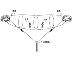
図1は本発明の親子局危険検出超音波送受信装置が適用される現場の一例を表す説明図であり、図2は本発明の参考形態に係る親子局危険検出超音波送受信装置の全体ブロック図である。図において、従来例と同様に、親局1は例えば重機車両のような移動体に設置され、子局2は作業員のヘルメット、ベスト等に設置される。親局1が設置される移動体は複数存在し、該複数の親局1は互いに、同一の子局2からの超音波を受信することができる近距離範囲内に接近することがあるものとする。
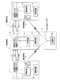
(First reference form)
FIG. 1 is an explanatory diagram showing an example of a site to which a parent-child station danger detection ultrasonic transmission / reception apparatus of the present invention is applied, and FIG. 2 is an overall block diagram of the parent-child station danger detection ultrasonic transmission / reception apparatus according to a reference form of the present invention. It is. In the figure, as in the conventional example, the
親局1は、送信センサ11、受信センサ12、送信センサ11及び受信センサ12の制御を行う制御回路13、警報装置14及び電波受信部(電波受信手段)15を備える。送信センサ11及び受信センサ12は、必要に応じて複数個のセンサからなり、全センサで形成される音場がその移動体の危険領域をカバーするように配置される。
The
一方の子局2は、受信センサ16、送信センサ17、応答回路18及び警報装置19を備える。子局2の受信センサ16及び送信センサ17も、必要に応じて複数個のセンサからなり、作業員がどのような姿勢にあっても親局1からの超音波を受信することができるように配置される。応答回路18は受信センサ16、送信センサ17を制御し、親局からの超音波を受信したときに送信センサに第2の超音波を送信させるものである。
One
親局1及び子局2とは別に発振局3が備えられる。発振局3は、現場において固定的に設置されるか、または親局1が設置される重機車両または別の移動体に設置されていてもよい。発振局3は、周期T毎の基準パルスを発振する発振器を有する送信機100と、該送信機100からの信号を電波パルスに変換して送信する送信アンテナ102とからなる電波送信手段、を備えている。
In addition to the
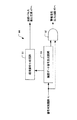
親局1の制御回路13と電波受信部15の詳細ブロック図を図3に示す。電波受信部15は、前記送信アンテナ102からの電波パルスを受信する受信アンテナ120と、該受信アンテナ120からの信号から基準パルスを出力する受信機122と、を備える。受信機122からの基準パルスは、制御回路13の送信パルス発生回路22に送られる。
A detailed block diagram of the
送信パルス発生回路22では、前記受信機122からの基準パルスと周波数f1の基準発信器24から基準パルスのタイミング毎に周波数f1の送信信号を発生し、この送信信号が増幅回路23で増幅されて送信センサ11を駆動する。帯域通過フィルタ/AMP25は、受信センサ12からの受信信号を受けて、周波数f2を中心とする周波数帯域の信号をろ波して、距離測定ゲート回路27へと送るものである。また、遅延回路26は、受信機122からの基準パルスを受けて所定時間遅延された信号を出力し、距離測定ゲート回路27へと送る。距離測定ゲート回路27は、遅延回路26からの信号に基づいて、危険距離、注意距離等の監視距離に対応する数種類のゲート信号を作る。信号判別回路28では、帯域通過フィルタ/AMP25からの信号に対してシュレシホールド値との比較、信号幅の所定値との比較等を行ってノイズカットをすると共に、これらの通過信号と距離測定ゲート回路27からのゲート信号とのANDを取り、このAND信号を警報信号出力回路29へと送る。警報信号出力回路29では、出力されたゲートから子局との距離に関する情報を得て、危険距離、注意距離等の危険度に応じて警報音の周波数や、警報音のインターバルを分別して警報音発生信号を出力する。警報音発生信号の他、警報表示発生信号及び制御用外部出力信号を含む警報作動信号が生成されて、警報装置14及び外部へと出力される。同時に警報信号出力回路29は遅延回路30へも警報作動信号を送る。遅延回路30では、所定時間(t3)遅延された信号を出力し、確認信号生成回路31は遅延回路30からの信号でトリガ信号を送信パルス発生回路22へと送る。
The transmission
図2に戻り、警報装置14は、前記警報音発生信号を受けて警報音を発生し、警報表示発生信号を受けて警報表示を行い、重機車両運転者に危険を喚起する。また、制御用外部出力信号を重機車両の駆動回路に入力して、重機車両の作動を停止させることもできる。但し、監視距離は1種類とし、警報音も1種類とすることもできる。
Returning to FIG. 2, the
子局2の応答回路18の詳細ブロック図を図4に示す。図4において、帯域通過フィルタ/AMP42は、受信センサ16からの受信信号を受けて、周波数f1を中心とする周波数帯域の信号を通過して、信号判別回路43へと送るものである。信号判別回路43は、シュレシホールド値との比較、信号幅の所定値との比較等を行ってノイズカットを行い、通過した信号を信号選別回路44へと送る。信号選別回路44では、親局1からの超音波が第1の超音波か第3の超音波かの選別を行い、第1の超音波であるときには返信パルス発生回路47に信号を送り、第3の超音波であるときには警報信号出力回路45へ信号を送るものである。
A detailed block diagram of the
信号選別回路44は、図5に示したように、信号判別回路43からの第1の超音波の受信信号に基づいて、所定時間(t2+t3)遅延された確認ゲート信号を生成する確認ゲート信号生成回路50と、信号判別回路43からの第1の超音波の受信信号に基づいて所定時間(t2)遅延されたトリガ信号を生成して、返信パルス発生回路47へと送る返信信号生成回路51と、確認ゲート信号と信号判別回路43からの信号のANDをとるANDゲート52とを備える。
As shown in FIG. 5, the
返信パルス発生回路47では、信号選別回路44からのトリガパルスを受けて、基準発信器46から周波数f2の返信信号を発生し、この返信信号が増幅回路48で増幅されて送信センサ17を駆動するようになっている。
The reply
以上のように構成された親子局危険検出超音波送受信装置の送信及び受信のタイミングを図6に基づいて説明する。 The transmission and reception timings of the parent / child station danger detection ultrasonic transmitting / receiving apparatus configured as described above will be described with reference to FIG.
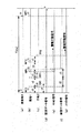
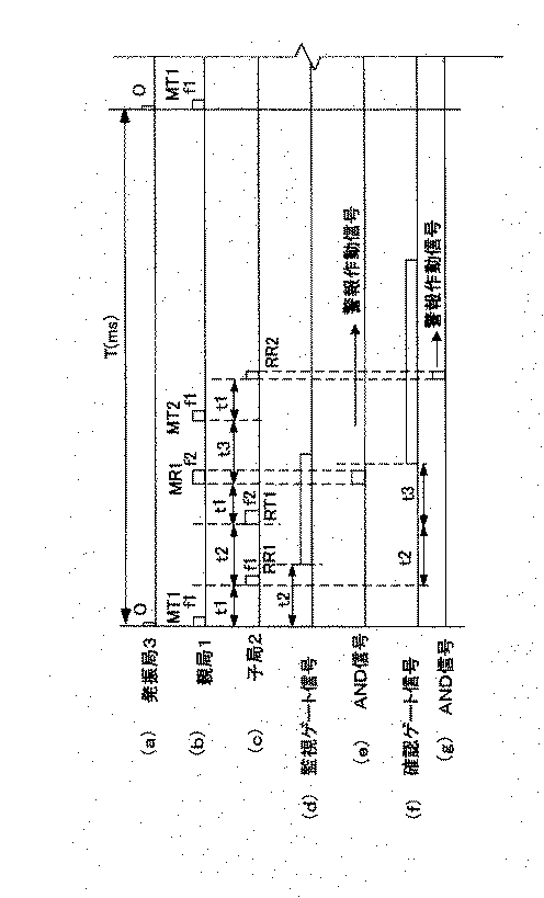
まず、発振局3の送信アンテナ102からは周期T毎に電波パルスOが送信されて(図6(a))、各親局1の受信アンテナ120によって受信される。このとき、すべての親局1は同時とみなせるタイミングで電波パルスを受信する。そして、この電波パルスをトリガとして、各親局1の送信センサ11から周波数f1でパルス幅w1の第1の超音波が送信される。この親局1の第1の超音波のための送信信号をMT1で表す。第1の超音波は、親局1と子局2の距離に比例した伝搬時間t1だけ遅れて子局2により受信される。この受信信号をRR1で表す。RR1の受信から子局2は、信号の残響や干渉を避けるために信号選別回路44で設定される遅延時間t2を経た後に周波数f2でパルス幅w2の第2の超音波を親局1に対して返信する。この第2の超音波のための返信信号をRT1で表す。第2の超音波は伝搬時間t1だけ遅れて親局1により受信される。この受信信号をMR1で表す。
First, a radio wave pulse O is transmitted from the transmission antenna 102 of the
この受信信号MR1は、距離測定ゲート回路27で設定された監視距離に対応する監視ゲート信号(尚、ここでは危険距離、注意距離のそれぞれの距離に対応するゲート信号を代表して監視ゲート信号として表す)(図6(d))とのANDがとられる。AND信号が出力された場合には(図6(e))、警報信号出力回路29から警報作動信号が出力される。同時に、さらに、残響や干渉を避けるために遅延回路30で設定される遅延時間t3の後、再び周波数f1でパルス幅w1の第3の超音波を送信する。この親局1の第3の超音波のための送信信号をMT2で表す。第3の超音波は、伝搬時間t1の後に子局2によって受信される。この受信信号をRR2で表す。この受信信号RR2を受けたということは、子局2が親局1に捕捉されていることを、言い換えれば、子局2が親局1の監視領域内にあることを意味しており、伝搬時間の遅れはあるものの(距離10mのとき約0.03秒)、遅延時間を含め0.1秒以内には親局1の危険情報を子局2で認識することができる。子局2の信号選別回路44にて、確認ゲート信号(図6(f))と受信信号RR2とのANDがとられ、AND信号が出力された場合には(図6(g))、警報信号出力回路45から警報作動信号が出力される。
The received signal MR1 is a monitoring gate signal corresponding to the monitoring distance set by the distance measurement gate circuit 27 (in this case, the gate signal corresponding to each of the dangerous distance and the attention distance is represented as a monitoring gate signal. AND) (FIG. 6 (d)). When the AND signal is output (FIG. 6E), an alarm activation signal is output from the alarm
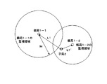
次に、図9に示すように、複数の親局1−1、1−2が互いに近距離に接近しており、子局2がその周辺に存在する場合を考える。親局1−1と子局2との距離をL1、親局1−2と子局2との距離をL1’とし、L1>L1’であるとする。
Next, as shown in FIG. 9, a case is considered in which a plurality of master stations 1-1 and 1-2 are close to each other and a
まず、発振局3の送信アンテナ102からは周期T毎に電波パルスOが送信されて(図7(a))、各親局1の受信アンテナ120によって受信される。親局1−1、1−2は、同期したタイミングで送信信号MT1に従い第1の超音波を送信する。子局2は、親局1−1よりも親局1−2の近傍にあるため、親局1−2との距離L1’に比例した伝搬時間t1’(=L1’/v)だけ遅れて親局1−2からの超音波を先に受信し、これに応答して、遅延時間t2遅れた返信信号RT1を生成する。子局2の信号選別回路44の確認ゲート信号生成回路50は、親局1−2からの超音波を受信した後、一定の時間は受信信号を受け付けないため、親局1−1との距離L1に比例した伝搬時間t1(=L1/v>t1’)だけ遅れて受信される親局1−1から送られた第1の超音波は無視される。子局2は返信信号RT1に従い第2の超音波を送信する。第2の超音波は、伝搬時間t1’後に親局1−2によって受信されるが、このときの処理は、先に説明した親局と子局が1:1の場合と同様であり、L1’が親局1−2の監視領域内の距離である場合には、親局1−2からは第3の超音波が送信されて、子局2にて警報作動信号が出力される。
First, a radio wave pulse O is transmitted from the transmission antenna 102 of the
また、第2の超音波は、伝搬時間t1後に親局1−1によって受信信号MR1として受信される。この場合の親局1−1での処理は、(t1+t1’)/2の伝搬時間に相当する距離L11’(=(t1+t1’)・v/2)に子局2がいる場合の処理と同じとなる。即ち、仮に、距離L11’が親局1−1の監視領域外の距離である場合には、親局1−1の監視ゲート信号(図7(d))と受信信号MR1とのAND信号がとられても、AND信号が出力されず(図7(e))、警報作動信号が出力されることはない。この場合、実際に子局2の存在している距離L1は必ず監視領域外であり、誤検出となることはない。
The second ultrasonic wave is received as the received signal MR1 by the master station 1-1 after the propagation time t1. In this case, the processing in the master station 1-1 is the same as the processing in the case where the
これに対して、距離L11’ (=(t1+t1’)・v/2)が親局1−1の監視領域内の距離である場合、親局1−1の監視ゲート信号(図8(d))と受信信号MR1とのAND信号が出力され(図8(e))、警報作動信号が出力される。この場合は、実際に子局2の存在している距離L1は、監視領域内である場合と監視領域外となる場合とがあり得る。子局2が実際に監視領域内にいる場合には、警報作動信号は出力されるべきであり、誤警報にはならない。一方、子局2が実際には監視領域外に存在している場合について、さらに検討する。この場合、親局1−1にて設定された監視領域に対応する距離をMとすると、
On the other hand, when the distance L11 ′ (= (t1 + t1 ′) · v / 2) is a distance within the monitoring area of the parent station 1-1, the monitoring gate signal of the parent station 1-1 (FIG. 8D). ) And the reception signal MR1 are output (FIG. 8E), and an alarm activation signal is output. In this case, the distance L1 where the
(第2参考形態)
次に、図10は、本発明の第2参考形態を表す親子局危険検出超音波送受信装置の全体ブロック図である。図において第1参考形態と同じ部分は同じ符号を付し、その詳細説明を省略する。
(Second reference form)
Next, FIG. 10 is an overall block diagram of the parent-child station danger detection ultrasonic transmitting / receiving apparatus representing the second reference embodiment of the present invention. In the figure, the same parts as those of the first reference embodiment are denoted by the same reference numerals, and detailed description thereof is omitted.
この参考形態においては、クロックパルスを出力するクロックパルス発生回路21を備えており、この発生回路21からのクロックパルスは、送信パルス発生回路22へと送られる。
In this reference embodiment includes a clock
電波受信部15は、発振局3からの時刻情報を包含する電波を受信し、これに基づき、基準パルスを出力する。送信パルス発生回路22では、クロックパルス発生回路21からのクロックパルスを計数する計数回路を備えており、所定パルス計数毎に、基準発信器24からの周波数f1の送信信号を発生する。この送信信号は、増幅回路23で増幅されて送信センサ11を駆動し、第1の超音波が送信される。
The
電波受信部15が次の電波を受信するまでは、送信パルス発生回路22の計数回路がクロックパルスを所定パルス計数するタイミングで、第1の超音波が送信される。電波受信部15から次の基準パルスが出力されると、送信パルス発生回路22の計数回路がリセットされて、この基準パルスを基準にして、再びクロックパルスの計数を開始する。
Until the radio
こうして、すべての親局1から送信される第1の超音波の送信タイミングを、電波の受信毎に同期させることができる。発振局3からの電波の送信周期が親局から第1の超音波を送信するべき周期よりも長いときには、その間は、各親局1におけるクロックパルスのタイミングで第1の超音波が送信されることになり、送信タイミングのずれが親局1間で発生するおそれがあるが、次の電波によって再び同期がとられるために、送信タイミングのずれは小さいもので収まり、すべての親局1からほぼ同期したタイミングで第1の超音波を送信することができる。
In this way, the transmission timings of the first ultrasonic waves transmitted from all the
この第2参考形態によれば、発振局3として専用の発振局のみならず、言い換えれば、第1の超音波を送信するべき周期Tごとに電波パルスを出力する発振局のみならず、任意の発振局を使用することができるようになる。従って、親局1及び子局2が存在する現場付近に設置される発振局3だけではなく、汎用の公共的な発振局3を使用することもできる。具体的には、汎用の発振局3として、電波時計で用いられる標準電波を送信する標準電波発信局やGPS電波を送信するGPS衛星を使用することができる。このような汎用の発振局3は、時刻情報を包含する電波を定期的に送信しており、この電波に基づいたタイミングで、すべての親局が第1の超音波を送信することができる。汎用の発振局3を使用すれば、発振局3の設定の手間が不要となり、現場での作業が容易になる。一方、トンネル内での作業のような標準電波発信局やGPS衛星からの電波が届かない現場では、現場に発振周期が任意の発振局3を置いて、使用すればよい。こうして、現場の状況にあわせて柔軟な使用が可能となる。
According to the second reference embodiment, not only a dedicated oscillation station as the
(実施形態)
次に、図11は、本発明の実施形態を表す親子局危険検出超音波送受信装置の全体ブロック図である。図において第1参考形態と同じ部分は同じ符号を付し、その詳細説明を省略する。
(Embodiment)
Next, FIG. 11 is an overall block diagram of the parent-child station danger detection ultrasonic wave transmitting / receiving apparatus representing the embodiment of the present invention. In the figure, the same parts as those of the first reference embodiment are denoted by the same reference numerals, and detailed description thereof is omitted.
この実施形態においては、各親局1が電波受信部15の代わりに電波送受信手段である電波送受信部15−1を備えており、複数の親局1が互いに電波送受信が可能な領域にある場合に、予め決められた規則に従いその中のいずれかの親局1の電波送受信手段が発振局3となり、その領域にある親局1は、その発振局3からの電波に同期して、各親局1の送信センサ11から周波数f1でパルス幅w1の第1の超音波を送信するようにしたものである。
In this embodiment, each
電波送受信部15−1は、送受信アンテナ130と、送受信機132と、クロックパルス発生回路134と、制御部136と、ID番号を記憶するメモリ138と、を備える。ID番号は、各親局1に固有の番号が予め割り当てられている。メモリ138は、その固有ID番号と、その後に取得した取得ID番号の両方のID番号を記憶しており、このID番号が、どの親局1の電波送受信手段15−1が発振局3となるかを決めるための情報となる。尚、取得ID番号の初期値は固有ID番号である。
The radio wave transmission / reception unit 15-1 includes a transmission /
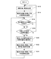
電波送受信部15−1の制御部136は、クロックパルス発生回路134で発生されるクロックパルスを元に周期T毎にID情報を包含する信号を作成して送受信機132へと送出し、送受信アンテナ130から電波を送信する(図12のステップS12)。この包含されるID情報はメモリ138に記録された送信元の親局1の取得ID番号である。制御部136から送受信機132へと信号が送出されるのと同時に、電波送受信部15−1の制御部136からの信号は、親局1の制御回路13の送信パルス発生回路22へと送られ、このタイミングで、第1の超音波が送信される(図12のステップS14)。
The
また、電波送受信部15−1は、互いに電波の送受信が可能な領域にある他の親局1からその親局1の固有のタイミングで発信されるコード情報を包含する電波を任意の時間に受信する(図12のステップS16)。この受信信号に含まれるID情報は、制御部136でデコードされて、メモリ138に記憶されたその親局1の取得ID番号との比較を行う(図12のステップS18)。ここで、前記予め決められた規則は、ID番号が小さい方の番号を採用するという規則とする。これは、常に固有ID番号が小さい方の親局1に従うことを意味し、固有ID番号が小さい方の親局1の電波送受信部15−1が発振局3となることを意味する。
In addition, the radio wave transmission / reception unit 15-1 receives a radio wave including code information transmitted at a specific timing of the
具体的には、仮に、受信したID情報が現在の取得ID番号よりも小さい場合には、受信したID番号を新たな取得ID番号として、メモリ138の取得ID番号を書き換える(図12のステップS20)と共に、その受信タイミングを元にして、周期T毎に取得ID情報を包含する電波を送受信アンテナ130から送信し始める(図12のステップS24)。同時にそのタイミングで、第1の超音波を送信する(図12のステップS26)。反対に、受信したID情報が現在の取得ID番号よりも大きい場合には、取得ID番号は書き換えずに、現在の取得ID番号のままで、自己の制御部136から周期T毎に送出される信号に基づき(図12のステップS12)、第1の超音波を送信する(図12のステップS14)。
Specifically, if the received ID information is smaller than the current acquired ID number, the acquired ID number in the
今、2つの親局1同士が互いに送受信可能に接近している場合を考える(図13を参照)。この場合、小さな固有ID番号N1を持つ親局1の電波送受信部15−1が発振局3となり、大きな固有ID番号N2(N2>N1)を持つ親局1は、この発振局3からの電波を受信したタイミングに基づき、第1の超音波を送信することになる。また、固有ID番号N1を持つ親局1は、固有ID番号N2を持つ親局1からの電波を受信するものの、その電波の受信には関係なく、自己の電波送受信部15−1を発振局3として、第1の超音波を送信する。よって、2つの親局1は同時に発振局3の電波の受信のタイミングに基づき、第1の超音波を送信することになる。また、固有ID番号N2を持つ親局1は、固有ID番号N1を持つ親局1とほぼ同期して、取得ID番号N1をコード情報として包含する電波を送信するようになる。
Consider a case where two
次に、別の固有ID番号N3(N2>N3>N1)を持つ親局1が固有ID番号N2を持つ親局1に接近し、互いに電波送受信可能に接近したものとする。但し、固有ID番号N3を持つ親局1と固有ID番号N1を持つ親局1とは、互いに電波送受信可能には接近していないものとする。この場合、固有ID番号N3を持つ親局1は、固有ID番号N2を持つ親局1からの取得ID番号N1をコード情報として包含する電波を受信するので、固有ID番号N2を持つ親局1の電波送受信部15−1が発振局3となり、固有ID番号N3を持つ親局1は、この発振局3からの電波を受信したタイミングに基づき、第1の超音波を送信することになる。さらに、固有ID番号N3を持つ親局1は、固有ID番号N1を持つ親局1とほぼ同期して、取得ID番号N1をコード情報として包含する電波を送信するようになる。結果として、多数の親局1の中である集合を考え、その集合は、当該集合に属する親局1が当該集合に属する親局1のいずれかと電波を送受信できる関係にある親局1の集まりであるとすると、その集合に属する親局1はすべてその集合中で最も小さな固有ID番号を持つ親局1と同期して第1の超音波を送信し、且つ、その最も小さな固有ID番号を取得ID番号として同期して電波を出力することとなる。
Next, it is assumed that the
この実施形態によれば、すべての親局1が電波送受信部15−1を備えているため、別途の発振局3の設置の手間が省け、また、複数の親局1の相対位置関係がどのようになっていても、いずれかの親局1の電波送受信部15−1が他のいずれかの親局1の発振局3として動作することができる。
According to this embodiment, since all the
尚、以上の各形態において、親局、子局それぞれの送信センサ及び受信センサは、別体のものを使用することができるが、広帯域の送受信一体型のセンサとすることも勿論可能である。 In each of the above embodiments, separate transmission sensors and reception sensors can be used for each of the master station and the slave station. However, it is of course possible to use a broadband transmission / reception integrated sensor.
1 親局
2 子局
3 発振局
11 送信センサ(第1送信センサ)
12 受信センサ(第2受信センサ)
13 制御回路
15 電波受信部(電波受信手段)
15−1 電波送受信部(電波送受信手段)
16 受信センサ(第2受信センサ)
17 送信センサ(第1送信センサ)
18 応答回路
100 送信機
102 送信アンテナ
1
12 Receiving sensor (second receiving sensor)
13
15-1 Radio transmitter / receiver (Radio transmitter / receiver)
16 Receiving sensor (second receiving sensor)
17 Transmitting sensor (first transmitting sensor)
18
Claims (3)
親局から送信された第1の超音波を受信するための第2受信センサと、前記第2の超音波を送信する第2送信センサと、第1の超音波を受信したときに第2送信センサに第2の超音波を送信させる応答回路とを備えた子局と、からなり
前記各親局は、所定の周期で電波を送信すると共に電波を受信する電波送受信手段を備えており、いずれかの親局に備えられた電波送受信手段が他のいずれかの親局に対する発振局となり、
前記発振局を持つ親局の第1送信センサは、該発振局からの電波を受信したタイミングに基づき第1の超音波を送信し、該親局の制御回路は、第1の超音波の送信から第2の超音波の受信までの時間差から子局が前記危険領域に存在するかどうかを検出し、
前記電波は発振局を決めるための情報を包含しており、その電波を受信する他の親局の電波送受信手段は、該送信された電波に包含された発振局を決めるための情報から予め定められた規則に基づき送信元の親局の電波送受信手段が発振局となるかどうかを判定し、送信元の親局の電波送受信手段が発振局となることが判定された場合には、発振局の電波とほぼ同期して電波を送信することを特徴とする親子局危険検出超音波送受信装置。 A plurality of first transmission sensors that transmit the first ultrasonic wave so as to cover the dangerous area, a first reception sensor that receives a second ultrasonic wave having a frequency different from the first frequency, and a control circuit. With the master station
A second reception sensor for receiving the first ultrasonic wave transmitted from the master station, a second transmission sensor for transmitting the second ultrasonic wave, and a second transmission when receiving the first ultrasonic wave a slave station and a response circuit for transmitting a second ultrasonic sensor, or Rannahli each master station is provided with a radio wave transmitting and receiving means for receiving a radio wave transmits a radio wave with a predetermined period, The radio wave transmitting / receiving means provided in any of the master stations becomes an oscillation station for any of the other master stations,
First transmitting sensor of the master station with the oscillation station transmits a first ultrasound based on the timing of receiving radio waves from emitting Fukyoku, the control circuit of the master station, transmission of the first ultrasound Detecting whether or not the slave station exists in the dangerous area from the time difference from the reception of the second ultrasonic wave to the second ultrasonic wave ,
The radio wave includes information for determining the oscillation station, and the radio wave transmitting / receiving means of the other master station that receives the radio wave is determined in advance from the information for determining the oscillation station included in the transmitted radio wave. It is determined whether or not the radio transmission / reception means of the transmission source parent station is an oscillation station based on the established rules, and if it is determined that the transmission / reception means of the transmission source parent station is an oscillation station, the oscillation station A parent-child station danger detection ultrasonic transmission / reception apparatus characterized by transmitting radio waves almost in synchronization with radio waves of
Priority Applications (1)
| Application Number | Priority Date | Filing Date | Title |
|---|---|---|---|
| JP2003405099A JP4100472B2 (en) | 2003-12-03 | 2003-12-03 | Parent / child station danger detection ultrasonic transmitter / receiver |
Applications Claiming Priority (1)
| Application Number | Priority Date | Filing Date | Title |
|---|---|---|---|
| JP2003405099A JP4100472B2 (en) | 2003-12-03 | 2003-12-03 | Parent / child station danger detection ultrasonic transmitter / receiver |
Publications (2)
| Publication Number | Publication Date |
|---|---|
| JP2005164441A JP2005164441A (en) | 2005-06-23 |
| JP4100472B2 true JP4100472B2 (en) | 2008-06-11 |
Family
ID=34727898
Family Applications (1)
| Application Number | Title | Priority Date | Filing Date |
|---|---|---|---|
| JP2003405099A Expired - Fee Related JP4100472B2 (en) | 2003-12-03 | 2003-12-03 | Parent / child station danger detection ultrasonic transmitter / receiver |
Country Status (1)
| Country | Link |
|---|---|
| JP (1) | JP4100472B2 (en) |
-
2003
- 2003-12-03 JP JP2003405099A patent/JP4100472B2/en not_active Expired - Fee Related
Also Published As
| Publication number | Publication date |
|---|---|
| JP2005164441A (en) | 2005-06-23 |
Similar Documents
| Publication | Publication Date | Title |
|---|---|---|
| AU2017206204B2 (en) | Proximity detection system with concurrent RF and magnetic fields | |
| US6614721B2 (en) | Collision avoidance method and system | |
| AU2008316786B2 (en) | Proximity detection system | |
| US8760520B2 (en) | System and method for tracking and monitoring personnel and equipment | |
| EP1706758B1 (en) | Combined radar and communications link | |
| AU2002211733A1 (en) | Collision avoidance method and system | |
| US8044839B2 (en) | Combined radar and communications link | |
| JP2003185735A (en) | Intruder detection system, method and receiver | |
| JP3964405B2 (en) | Alarm device | |
| US20190101612A1 (en) | Electronic device with distance detection function and distance detection method thereof | |
| JP4100472B2 (en) | Parent / child station danger detection ultrasonic transmitter / receiver | |
| JPH07140241A (en) | Locating system for moving body | |
| JP2005106603A (en) | Pulse wave radar apparatus | |
| JP5243974B2 (en) | Ultrasonic transceiver | |
| JPH07311887A (en) | Approach detector | |
| JP2006084428A (en) | Obstacle detection device | |
| JP3202865B2 (en) | Parent-child station mutual danger recognition type ultrasonic transceiver | |
| JP2005249707A (en) | Sensor system and sensor device used for sensor system, and receiving device | |
| JP2897535B2 (en) | Transponder type safety device | |
| JPH0483189A (en) | Ultrasonic sensor | |
| JP2006125947A (en) | Radar system | |
| KR102804339B1 (en) | Object detection device mounted on a vehicle to detect surrounding objects and the control method thereof | |
| JPH07168986A (en) | Proximity detection system, and parent and child units used in the system | |
| JPH05281353A (en) | Work warning device | |
| KR100398144B1 (en) | Alarm occurring method of radar |
Legal Events
| Date | Code | Title | Description |
|---|---|---|---|
| A521 | Request for written amendment filed |
Free format text: JAPANESE INTERMEDIATE CODE: A523 Effective date: 20041228 |
|
| A711 | Notification of change in applicant |
Free format text: JAPANESE INTERMEDIATE CODE: A711 Effective date: 20041228 |
|
| RD03 | Notification of appointment of power of attorney |
Free format text: JAPANESE INTERMEDIATE CODE: A7423 Effective date: 20041228 |
|
| RD13 | Notification of appointment of power of sub attorney |
Free format text: JAPANESE INTERMEDIATE CODE: A7433 Effective date: 20041228 |
|
| A521 | Request for written amendment filed |
Free format text: JAPANESE INTERMEDIATE CODE: A821 Effective date: 20041228 |
|
| A521 | Request for written amendment filed |
Free format text: JAPANESE INTERMEDIATE CODE: A523 Effective date: 20050311 |
|
| A621 | Written request for application examination |
Free format text: JAPANESE INTERMEDIATE CODE: A621 Effective date: 20050808 |
|
| A977 | Report on retrieval |
Free format text: JAPANESE INTERMEDIATE CODE: A971007 Effective date: 20070704 |
|
| A131 | Notification of reasons for refusal |
Free format text: JAPANESE INTERMEDIATE CODE: A131 Effective date: 20070710 |
|
| A521 | Request for written amendment filed |
Free format text: JAPANESE INTERMEDIATE CODE: A523 Effective date: 20070910 |
|
| TRDD | Decision of grant or rejection written | ||
| A01 | Written decision to grant a patent or to grant a registration (utility model) |
Free format text: JAPANESE INTERMEDIATE CODE: A01 Effective date: 20080226 |
|
| A61 | First payment of annual fees (during grant procedure) |
Free format text: JAPANESE INTERMEDIATE CODE: A61 Effective date: 20080311 |
|
| FPAY | Renewal fee payment (event date is renewal date of database) |
Free format text: PAYMENT UNTIL: 20110328 Year of fee payment: 3 |
|
| R150 | Certificate of patent or registration of utility model |
Ref document number: 4100472 Country of ref document: JP Free format text: JAPANESE INTERMEDIATE CODE: R150 Free format text: JAPANESE INTERMEDIATE CODE: R150 |
|
| FPAY | Renewal fee payment (event date is renewal date of database) |
Free format text: PAYMENT UNTIL: 20110328 Year of fee payment: 3 |
|
| FPAY | Renewal fee payment (event date is renewal date of database) |
Free format text: PAYMENT UNTIL: 20120328 Year of fee payment: 4 |
|
| R250 | Receipt of annual fees |
Free format text: JAPANESE INTERMEDIATE CODE: R250 |
|
| FPAY | Renewal fee payment (event date is renewal date of database) |
Free format text: PAYMENT UNTIL: 20130328 Year of fee payment: 5 |
|
| R250 | Receipt of annual fees |
Free format text: JAPANESE INTERMEDIATE CODE: R250 |
|
| FPAY | Renewal fee payment (event date is renewal date of database) |
Free format text: PAYMENT UNTIL: 20170328 Year of fee payment: 9 |
|
| R250 | Receipt of annual fees |
Free format text: JAPANESE INTERMEDIATE CODE: R250 |
|
| R250 | Receipt of annual fees |
Free format text: JAPANESE INTERMEDIATE CODE: R250 |
|
| R250 | Receipt of annual fees |
Free format text: JAPANESE INTERMEDIATE CODE: R250 |
|
| R250 | Receipt of annual fees |
Free format text: JAPANESE INTERMEDIATE CODE: R250 |
|
| R250 | Receipt of annual fees |
Free format text: JAPANESE INTERMEDIATE CODE: R250 |
|
| R250 | Receipt of annual fees |
Free format text: JAPANESE INTERMEDIATE CODE: R250 |
|
| R250 | Receipt of annual fees |
Free format text: JAPANESE INTERMEDIATE CODE: R250 |
|
| LAPS | Cancellation because of no payment of annual fees |