JP4100016B2 - Lighting device - Google Patents
Lighting device Download PDFInfo
- Publication number
- JP4100016B2 JP4100016B2 JP2002077330A JP2002077330A JP4100016B2 JP 4100016 B2 JP4100016 B2 JP 4100016B2 JP 2002077330 A JP2002077330 A JP 2002077330A JP 2002077330 A JP2002077330 A JP 2002077330A JP 4100016 B2 JP4100016 B2 JP 4100016B2
- Authority
- JP
- Japan
- Prior art keywords
- light
- rod integrator
- color wheel
- color
- opening
- Prior art date
- Legal status (The legal status is an assumption and is not a legal conclusion. Google has not performed a legal analysis and makes no representation as to the accuracy of the status listed.)
- Expired - Fee Related
Links
Images


Landscapes
- Light Guides In General And Applications Therefor (AREA)
- Optical Elements Other Than Lenses (AREA)
- Microscoopes, Condenser (AREA)
- Mechanical Light Control Or Optical Switches (AREA)
- Projection Apparatus (AREA)
Description
【0001】
【発明の属する技術分野】
本発明は、カラーリキャプチャ方式の照明装置に関するものである。
【0002】
【従来の技術】
1つの光源からの光を時分割して変調する光学系を備えた、いわゆる単板式のプロジェクタなどの画像表示装置は、回転式のカラーフィルタであって、白色光を選択的に透過または吸収させて原色に時分割するカラーホイール(カラーフィルタ)と、光の強度分布を均一にするインテグレータとを備えており、時分割された色の光束をマイクロミラーデバイスなどのライトバルブで変調し、スクリーンに投射してカラー画像を合成する。
【0003】
この従来のシステム(光学系)のプロジェクタでは、カラーフィルタの後方に、内周が反射面となった筒型あるいは棒状のロッドインテグレータを配置しており、フィルタで白色光を色分離する際に、フィルタを通らない光は利用されない。これが、光の利用効率の低下の大きな要因となっている。
【0004】
【発明が解決しようとする課題】
これに対して、カラーリキャプチャ方式が提案されている。図9に示したプロジェクタ1は、カラーリキャプチャ方式の照明装置100と、照明装置100から色分離されて出力された各色の光束72R〜72Bを伝達するリレーレンズ49と、このレンズ49からの光束72R〜72Bを画像データにより変調するマイクロミラーデバイス50と、このミラーデバイス50から出力される表示光74をスクリーン58に投射してカラー画像を形成する投射レンズ52とを備えている。
【0005】
カラーリキャプチャ方式の照明装置100は、キセノンランプなどから白色の光71を出力する光源部12と、反射性の内周面24を備えた角柱状のインテグレータとなるロッドインテグレータ120と、白色の入射光71を時分割するカラーホイール40とを備えており、これらが順番に配置されている。照明装置100の光源部12から照射された白色の光束71は、ロッドインテグレータ120で、ライトバルブ50の形状に合わせて強度分布が均一化され、カラーホイール40から時間および空間的に色分割された状態で出力される。すなわち、カラーホイール40は、特定の色を透過し他の色の光を反射する分光透過性のダイクロイック膜(ミラー)41R、41Gおよび41Bが螺旋状などの適当な形状に組み合わされている。このため、カラーホイール40では、各色のダイクロイック膜41R〜41Bで色分離が行われ、所定の色の光が出力されると共に、ダイクロイック膜41R〜41Bを透過しない光はロッドインテグレータ120の側に反射される。
【0006】
この照明装置100では、カラーホイール40を透過しなかった光は、捨てられずに反射されて、ロッドインテグレータ120に戻され、ロッドインテグレータ内を伝播して、再びカラーホイール40に出力される。そのときに異なる色のダイクロイック膜41R〜41Bに当たると、それを透過して出力される可能性があり、カラーホイール40を透過しない光を再利用できるようになっている。このため、光のロスが減り、従来のカラー表示方法に比べて、光の利用効率を向上させることができるので、明るいカラー表示が実現できる。
【0007】
しかしながら、このカラーリキャプチャ方式の照明装置であっても光の利用効率は100パーセントにはならず、ある程度の光はロスとなり使用されない。したがって、カラーリキャプチャ方式の照明装置の光の利用効率をさらに向上できる可能性がある。たとえば、図10に示すように、ロッドインテグレータ120の出射側の出口23と、カラーホイール40は、カラーホイール40が旋回するために適当な間隔を設けて配置されている。このため、出射側の出口23の端でカラーホイール40に照射され、カラーホイール40を透過せずに反射された光71は、ロッドインテグレータ120の出射側20bの外端面131に当たり、ロッドインテグレータ120内へ戻らずロスとなる。
【0008】
したがって、光の利用効率を向上させるには、ロッドインテグレータ120とカラーホイール40との隙間をできるだけ小さくすることにより、外端面131にカラーホイール40から反射された光が当らないようにすることが望ましい。しかしながら、カラーホイール40は回転駆動する面ぶれの可能性があり、それに対処するためのクリアランスも必要である。したがって、組み立て精度を考慮すると、カラーホイールとロッドインテグレータを密着させることは不可能であり、外端面に反射された光のロスを低減することはできない。
【0009】
そこで、本発明では、カラーリキャプチャ方式を用いた照明装置において、ロッドインテグレータとカラーホイールとの隙間をある程度確保しても、より光の利用効率を向上することができる照明装置およびロッドインテグレータを提供することを目的としている。そして、本発明の照明装置を使用することにより、さらに明るく、高画質なカラー画像を表示できる画像表示装置を提供することを目的としている。
【0010】
【課題を解決するための手段】
このため、本発明においては、ロッドインテグレータの出射側の開口の外周部分が、カラーホイールで反射された光を、ロッドインテグレータの中心軸の方向に反射する鏡面である照明装置として提供する。出射側の開口の外周部分をロッドインテグレータの光軸方向に向けることで、出射側の外端面に当っても、それがロスにならないようにすることにより、ロッドインテグレータをカラーホイールに密着させなくても光の利用効率を向上できる。
【0011】
すなわち、本発明においては、断面が略四角形のロッドインテグレータであって、反射性の内周面を備え、出射側の開口の外周部分が、当該ロッドインテグレータの中心軸の方向に傾いた鏡面になっているロッドインテグレータを提供する。したがって、本発明の照明装置は、反射性の内周面を備えた断面が略四角形のロッドインテグレータと、ロッドインテグレータの入射側の開口に光を供給する光源と、ロッドインテグレータの出射側に配置されたカラーホイールであって、複数の原色の光の内、1つの色の光を透過し他の色の光を反射する分光透過部分を備え、各々の色の分光透過部分がロッドインテグレータの出射側の開口を分割するように回転するカラーホイールとを有する照明装置であって、ロッドインテグレータの出射側の開口の外周部分が、カラーホイールで反射された光をロッドインテグレータの中心軸の方向に反射する鏡面となっている。
【0012】
カラーホイールと対面するロッドインテグレータの出射側の開口の外周部分、たとえば、厚みのある鏡面を組み合わせたロッドインテグレータであれば、その外端面を傾斜した鏡面とする。この外周部分に設けられた鏡面を、ロッドインテグレータの中心軸の方向、すなわち光軸方向に向けることで、カラーホイールに反射して出射側の開口の外周部分に当った光は、ロッドインテグレータから外の方向に反射されずに、再びロッドインテグレータの中心軸の方向に反射される。したがって、ロッドインテグレータの出射側の開口の外周部分から反射された光は、ロッドインテグレータの出射側の開口に面したカラーホイールに当り、カラーホイールを透過できる色の光であれば、カラーホイールを透過して出力され、カラーホイールを透過できない色の光であれば、カラーホイールで反射されてロッドインテグレータ内に戻される。このため、ロッドインテグレータの出射側の外端面に反射された光もロスにならないので、ある程度、カラーホイールで反射された光がロッドインテグレータの出射側の開口の外周部分に当ることが容認できる。したがって、ロッドインテグレータとカラーホイールのギャップをある程度確保した状態で光の利用効率を向上することができ、カラーホイールの取り付け誤差や、モータの軸精度に起因する面ぶれによる変動も加味した、実用に即したカラーリキャプチャ方式の照明装置であって、光の利用効率がさらに向上された照明装置を本発明により提供できる。
【0013】
この効果は次のように理解することも可能である。カラーホイールから反射した光をロッドインテグレータに効率良く再捕捉しようとすると、出射側の開口を広げることが望ましい。しかしながら、再補足しようとして出射側の開口を広げれば、カラーホイールに照射される面積も広がるから再補足できない光量は削減されない。したがって、カラーホイールに照射される光束の面積を広げずに、再補足する面積だけを広げることができれば、光の利用効率をさらに向上することができる。そのために、上記では、出射側の開口の外周部分だけを広げることにより、ロッドインテグレータの長さに比べると充分に薄い捕捉用の光学部分を形成し、カラーホイールに出射される光束の面積を広げずに、カラーホイールで反射された光を捕捉する面積だけを広げていると云える。
【0014】
すなわち、光軸に沿って延び、周面で光を反射しながら伝達するロッドインテグレータであって、当該ロッドインテグレータの出射側の開口に、当該ロッドインテグレータの長さに対して充分に薄い光学部分を設け、この光学部分で、当該出射側の開口より大きく、出射側からの光を捉えることができる捕捉開口を形成し、捕捉された光を光軸の方向に変えれば良い。したがって、本発明には、光軸に沿って延び、周面で光を反射しながら伝達するロッドインテグレータと、ロッドインテグレータの入射側の開口に光を供給する光源と、ロッドインテグレータの出射側に配置されたカラーホイールであって、複数の原色の光の内、1つの色の光を透過し他の色の光を反射する分光透過部分がロッドインテグレータの出射側の開口を分割するように回転するカラーホイールとを有し、さらに、ロッドインテグレータの出射側の開口に配置された、当該ロッドインテグレータの長さに対して充分に薄い光学部分であって、当該出射側の開口より大きく、カラーホイールに反射された光を捉えることができる捕捉開口を備え、捕捉された光を光軸の方向に変える光学部分を有する照明装置も含まれる。また、そのようなロッドインテグレータ自身も含まれる。
【0015】
光学部分は、ホログラムミラーやフレネルミラーのように厚さがなくて光の反射方向を変えられるものを利用できる。また、周面が全反射面となった薄いガラス板をガラスロッドレンズタイプのロッドインテグレータと組み合わせることも可能である。また、薄いスカート状で内面がミラーとなった光学部分を設けても良い。
【0016】
そして、本発明のロッドインテグレータを有する照明装置と、この照明装置から出力された各色の光束に基づいて画像データを形成するライトバルブと、このライトバルブからの光を投影するレンズシステムとを有するプロジェクタなどの画像表示装置においては、さらに、明るく、高品質なカラー画像を出力することが可能となる。
【0017】
ロッドインテグレータの出射側の開口の外周部分に備えられた鏡面は、曲面であっても良いが、その平面状の鏡面でも良く、平面鏡であれば経済的である。さらに、光源がランプとリフレクタを備えたものである場合は、ロッドインテグレータの中心軸に対して傾いた代表角度を持つ角度分布の光がロッドインテグレータに入力されるので、ロッドインテグレータの出射側の開口の外周部分の鏡面の法線を中心軸に対して代表角度にほぼ等しい角度で傾けることにより、カラーホイールから反射された光に対する鏡面の有効面積を最も大きくすることができる。したがって、ロッドインテグレータの外端面に設ける、傾いた鏡面の面積が最も小さくなり、光のロスを効率良く防止することができる。
【0018】
このため、リフレクタを備えた光源から入射される光の強度分布で高い強度を示す角度は5度〜20度程度の範囲になるので、ロッドインテグレータの出射側の開口の外周部分の傾いた鏡面の法線は中心軸に対し5度から20度の範囲で傾いていることが望ましい。さらに、8度〜15度の角度の範囲でピークを持つので、出射側の開口の外周部分の傾いた鏡面の法線は中心軸に対して8度から15度の範囲で傾けることがさらに好ましい。
【0019】
また、ロッドインテグレータの出射側の開口の外周部分の鏡面をロッドインテグレータの中心軸に投影した長さは、0.5mm以下とすることが望ましい。ロッドインテグレータの出射側の開口の外周部分の傾いた鏡面の面積を大きくすると、中心軸に平行な反射面を備えたロッドインテグレータ自体の端がカラーホイールから離れることになり、カラーホイールで反射された光がロッドインテグレータの出射側の開口の外周部分にも反射しないでロスとなる可能性が増加する。すなわち、出射光束の面積自体が広がる可能性がある。したがって、光学部分の厚みは0.5mm以下とすることが望ましい。さらに、鏡面をロッドインテグレータの中心軸に投影した長さを、0.1mm程度、すなわち、光学部分の厚みを0.1mm程度に縮めることにより、いっそうロスの少ない照明装置を提供できる。
【0020】
ロッドインテグレータは、ロッドレンズで構成することも可能である。また、ロッドインテグレータは、内周面を構成する4枚の平面鏡を組み合わせることにより組み立てることが可能であり、それら平面鏡の出口側の端を上記の傾いた鏡面とすることにより、上記の作用および効果を備えたロッドインテグレータおよび照明装置を提供できる。
【0021】
ロッドインテグレータの出射側の開口の外周部分の縁を傾けることで、出射側の開口の外周部分からのロスを防止できるので、カラーホイールとのギャップを確保することができる。本願の発明者らのシミュレーションによると、殆ど光をロスしないで0.3mm程度のギャップを確保することが可能であり、カラーホイールのクリアランスを十分に確保しながら、光のロスのさらに少ない、光の利用効率のさらに高いカラーリキャプチャ式の照明装置を提供することができる。
【0022】
【発明の実施の形態】
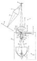
以下に図面を参照しながら本発明の実施の形態を説明する。図1に、本発明に係る照明装置10を用いたプロジェクタ1の概略構成を示してある。本例のプロジェクタ1も、カラーリキャプチャ方式の照明装置10と、照明装置10から色分離されて出力された各色の光束72R(赤色)、72G(緑色)および72B(青色)を伝達するリレーレンズ49と、このレンズ49からの光束72R〜72Bを画像データにより変調するマイクロミラーデバイス50と、このミラーデバイス50から出力される表示光74をスクリーン58に投射してカラー画像を形成する投射レンズ52とを備えている。
【0023】
本例のカラーリキャプチャ方式の照明装置10も、キセノンランプなどから白色の光71を出力する光源部12と、反射性の内周面24を備えた角柱状のインテグレータとなるロッドインテグレータ20と、白色の入射光71を時分割するカラーホイール40とを備えており、これらが順番に配置されている。したがって、本例の照明装置10においても、光源部12から照射された白色の光束71は、ロッドインテグレータ20で、ライトバルブ50の形状に合わせて強度分布が均一化され、カラーホイール40から時間および空間的に色分割された状態で出力される。すなわち、カラーホイール40は、特定の色を透過し他の色の光を反射する分光透過性のダイクロイック膜(ミラー)41R、41Gおよび41Bが螺旋状などの適当な形状に組み合わされているので、各色光72R〜73Bが時間および空間的に分離されて出力される。
【0024】
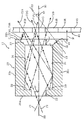
図2〜図4に、本例のロッドインテグレータ20の概略構成を示してある。本例のロッドインテグレータ20は、内周面24が反射面となった全体が角柱状で中空のインテグレータあり、入射側20aには、図3に示すように中心軸80を中心とする円形の開口22が設けられている。入射側20aの内、円形の開口22を除く部分は、ロッドインテグレータ20の内側に向いた面(内端面)29が反射面となり、カラーホイール40で反射されてロッドインテグレータ20に戻された光を再度、カラーホイール40の方向にリキャプチャするリキャプチャミラー29として機能する。
【0025】
ロッドインテグレータ20の出射側20bは、図4に示すように、ロッドインテグレータ20の断面と同じ四角形の開口23となっている。本例のロッドインテグレータ20は、内周面24を形成する4枚の平面鏡39a、39b、39cおよび39dが、内周面24の断面が長方形をなすように組み合わされて形成されている。これらの平面鏡39a〜39dの出射側20bの外端面31は基本的には内周面24と直角になっているが、その内側の部分はロッドインテグレータ20の中心軸80の方向に傾いた鏡面32となっている。したがって、ロッドインテグレータ20の出射側20bは、外周方向にスカート状に鏡面が広がった構成となっている。
【0026】
ロッドインテグレータ20の出口側の斜めの鏡面32は、ガラスをプレス技術により成形し、その際に上述したようにテーパ状に加工することも可能である。あるいは、アルミニウムなどの高反射率を備えた金属を、ダイヤモンドを用いて鏡面切削して、形成することもできる。また、内側に傾斜した鏡面32を備えたアダプタを形成しておき、図10に示したロッドインテグレータ120の出口側に装着することによっても出口側の内側に斜めになった鏡面32を備えたロッドインテグレータ20を提供することができる。そして、ロッドインテグレータ20の出射側の開口23の直後に、微小なギャップWを開けて、回転式のカラーホイール40が開口23と対面するように配置されている。
【0027】
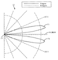
本例の照明装置10の光源部12は、ランプ13とリフレクタ14の組合せでランプ13から出力された光を、ロッドインテグレータ20の入力側の開口22に導いている。したがって、光源部12からは図5に示すように中心軸80に対して角度θ1の方向に強い分布を持った光71が、ロッドインテグレータ20に入力される。このため、図2に示すように、ロッドインテグレータ20の中心軸80に対して角度θ1の強い分布を持った光束71がロッドインテグレータ20に入射されると、ロッドインテグレータ21の内周面24で反射されて出口側20bの開口23に至り、面しているカラーホイール40に照射される。カラーホイール40の緑色の光を透過するダイクロイック膜41Gの部分に照射された光は、緑色の光72Gのみがカラーホイール40を透過してライトバルブ50の側に出力され、その他の色の光はロッドインテグレータ20の側に戻される。そして、ロッドインテグレータ20の内部で反射されて再びカラーホイール40に照射されたときに、緑色の色以外の光を透過するダイクロイック膜41Rあるいは41Bに照射されると、赤色の光あるいは青色の光が出力され、残りの色の光は再びロッドインテグレータ20に戻される。
【0028】
このような入射光71のうち、図2に示した状態では出力側の開口23の上端に位置するダイクロイック膜41Rに照射された光に着目すると、本例のロッドインテグレータ20では、ダイクロイック膜41Rで反射された光、たとえば、緑色の光71Gは、ロッドインテグレータ20の端面31の内側に傾斜した反射面32に至る。反射面32は、法線33が光軸80の方向に向くように傾斜しているので、反射面32に当った光71Gは、ほぼ同じ経路を通ってカラーホイール40の方向に反射される。そのとき、カラーホイール40が動いて、ダイクロイック膜41Gに反射面32で反射された光71Gが照射されれば、カラーホイール40を透過してライトバルブ50の側に出力される。一方、反射面32で反射された光71Gが照射された場所が、緑色の光を反射するダイクロイック膜41Rまたは41Bであれば、カラーホイール40で反射された光71Gは再びロッドインテグレータ20の内部に導かれる。したがって、上記と同様に、ロッドインテグレータ20で多重反射してカラーホイール40に再び照射されたときにダイクロイック膜41Gに当ればライトバルブ50に出力される。
【0029】
このように、本例のロッドインテグレータ20を採用した照明装置10においては、カラーホイール40に反射されて、ロッドインテグレータ20の出射側の開口23の端面31に当った光であっても、ロッドインテグレータ20の外側に反射されることはなく、ロッドインテグレータ20の内側、すなわち、光軸(中心軸)80の方向に反射される。したがって、外端面31で反射されてロスとなる光量は非常に小さい。特に本例の外端面31の内側すなわち出射側の開口の外周部分の鏡面32は、その法線33が中心軸80に対して角度θ2だけ傾いている。このため、ロッドインテグレータ20に入力される光71の内、最も強度の高い角度θ1の成分がカラーホイール40で反射されて外端面の傾斜した鏡面32に至ったときに、鏡面32に対して垂直に入射する状況となり、鏡面32の法線方向、すなわち、中心軸80の方向に確実に反射される。
【0030】
そして、最も強度の高い角度θ1に隣接する入射光束71の光量の殆どの成分も、鏡面32により中心軸80の方向に反射される。したがって、傾斜した反射面32に照射された光で、中心軸80から離れた方向に反射されてロスとなる成分を最小にすることができ、照明装置10における光の利用効率を最も高くすることができる。
【0031】
このように、光のロスを最小にするには、鏡面32の傾き角度θ2は、光源12から出力される光の角度分布の代表角度θ1に一致していることが望ましい。光源12から出力される光の角度分布は、光源部12の部品や組立て公差などにより必ずしも一定ではないが、出力光(ロッドインテグレータ20に対する入力光)71の角度分布の中心軸80に対する代表角度θ1は、8度から15度の範囲の範囲である。したがって、鏡面32の法線33の中心軸80に対する角度も8度から15度の範囲にすることが望ましく、たとえば、鏡面32の法線33と中心軸80とを角度θ2を12度に設定することができる。光源部12のランプ13の種類やリフレクタ14の種類の組合せが変わることにより、出力される光の角度分布はさらに大きく変わるが、出力される光71の角度分布はある程度限られており、殆どの光源部では、出力される光の代表角度となる、最も強度の高い分布の角度θ1は中心軸80に対し5度から20度の範囲に入る。したがって、ロッドインテグレータ20の出力側の鏡面32の法線33の角度θ2も、中心軸80に対し5度から20度の範囲で傾けることが望ましい。したがって、本例のように、鏡面32の角度θ2を12度に設定したロッドインテグレータ20は、殆どの種類の光源に対して光の利用効率を向上できるものである。
【0032】
このように、ロッドインテグレータ20の出力側20bの外端面31の内側すなわち出射側の開口の外周部分を斜めの鏡面32とすることにより、カラーホイール40から外端面31に向けて反射された光を中心方向に反射することにより光の利用効率を向上できる。その反面、ロッドインテグレータ20の出力側に斜めの鏡面32を形成することにより、光軸80と平行なロッドインテグレータの内周面24は出力側20bの端から後退することになり、内周面24とカラーホイール40との間が開く。したがって、出力側20bの近傍の内周面24により中心軸80に向かって反射されてカラーホイール40に向かう光線が、内周面24に反射されずにカラーホイール40に向かい、カラーホイール40によりロッドインテグレータ20の外側へ向けて反射される可能性がある。あるいは、斜めの鏡面32に当たっても中心軸80の方向には反射されない可能性もあり、これらの光線はロスになる可能性がある。このため、ロッドインテグレータ20の出力側20bの斜めの鏡面32の面積はできるだけ小さいことが望ましい。
【0033】
図6に、ロッドインテグレータ20の出力側20bに中心軸80に投影した長さLが0.1mmとなる斜めの鏡面32を設けた照明装置10からの出力される光量と、図10を参照しながら説明したロッドインテグレータ120の出力側20bに斜めの鏡面が設けられていない照明装置100から出力される光量が、ロッドインテグレータ20または120の出力側20bとカラーホイール40との隙間Wにより変化する様子をシミュレーションした結果を示してある。本図からわかるように、ロッドインテグレータ20の出力側に斜めの鏡面32を設けた照明装置10では、ロッドインテグレータ20とカラーホイール40とのギャップWが大きくなっても出力される光量は大きくは減少しない。したがって、ロッドインテグレータ20の出力側に内側に斜めになった反射面32を設けることにより光の利用効率が向上していることが分かる。そして、傾斜した反射面32の面積は、中心軸80に投影した長さLが0.1mm程度で十分な効果が得られる。
【0034】
この長さLは、できるだけ小さい方が望ましいが、小さすぎると、上述したような傾斜した反射面32による効果が得られない。一方、長さLが大きくなると、逆に、光のロスが増大する可能性がある。このシミュレーション結果から分かるように長さLは0.1mm程度でも効果がある。長さLが大きくなると、カラーホイール40で反射された光の利用効率が向上するが、それと同時にロッドインテグレータ20の内面24を反射してカラーホイール40に照射される光量が減少し、照明装置10としての光の利用効率は低くなる。
【0035】
本願の発明者らの検討によると、反射性の斜面32を中心軸80に投影した長さLが0.5mm程度までは傾斜した反射面32の効果が得られるが、それ以上に長さLが大きくなると、内周面24の面積が減ってロスが大きくなり、照明装置10から出力される光量が減る可能性がある。したがって、ロッドインテグレータ20の出力側20bの傾いた鏡面32を中心軸80に投影した長さLは0.1〜0.5mm程度の範囲内であることが望ましい。
【0036】
また、図6から分かるように、ロッドインテグレータ20の出口側に内側に傾斜した鏡面32を設けることにより、ロッドインテグレータ20とカラーホイール40とのギャップWが0.3mm程度までは照明装置10から出力される光量がほとんど変わらない。これに対し、図10に示したロッドインテグレータ120の出力側に傾斜した鏡面がない照明装置100であると、ギャップWが0.1mm程度から出力される光量が大きく減少する。したがって、図10に示した照明装置100であるとロッドインテグレータ120とカラーホイール40とのギャップWを、0.1mm程度あるいはそれ以下にした場合の光量を、本例の照明装置10であるとギャップWが0.3mm程度あるいはそれ以上で確保することができる。これは、ロッドインテグレータ20の出口側に反射光を捕捉する大きな面を鏡面32で形成することにより、ギャップWをある程度まで大きくしても、ギャップWが小さいときと同様にカラーホイールからの反射光を捉えてリサイクル効率を維持できることを意味する。すなわち、ロッドインテグレータ20の出力側20bに傾斜した鏡面32を設けることにより、ロッドインテグレータ20の外端面31におけるロスを大幅に改善することができ、それが光量の低下がそれほど起きない範囲で利用できるギャップWの値が大きく広がる結果として得られている。
【0037】
カラーホイール40は回転駆動される光学製品であり、カラーホイール40の組み立て誤差、製品公差や、面ぶれを吸収するためにある程度のギャップWが必要になるが、本例の照明装置10であれば、ギャップWが0.3mm程度という製品を組み立てる上でリーズナブルな現実的な精度にすることができる。これに対し、出力側に傾斜した鏡面のないロッドインテグレータを採用した照明装置100においては、本例の照明装置10と同じ光量を得ようとするとギャップWを0.1mm以下に収める必要が生じ、公差などを考慮すると非現実的な値となる。
【0038】
このように、本例の照明装置10はロッドインテグレータ20の出射側20bの端の内側を光軸80の方向に傾斜した鏡面32とすることにより、カラーリキャプチャ方式の照明装置10の光の利用効率をさらに向上することができる。したがって、本例の照明装置が高いので、コンパクトで高出力な照明装置として提供することが可能である。さらに、本例の照明装置10を採用した、図1に示したプロジェクタ1をはじめとする投影型あるいは直視型の表示装置や、プリンタなどを含めた映像表示装置であって、コンパクトで明るく、鮮明な画像を表示することができる画像表示装置を提供することができる。画像表示装置1で利用される光はRGB系の3原色の光に限らず、カラーホイール41で分光透過される光であれば、光の色は問わずに本発明を適用できることはもちろんである。
【0039】
本例の照明装置10は、図1に示したような、マイクロミラーを駆動するミラーデバイス50などの反射側の映像デバイスをライトバルブとして使用できる。反射型のライトバルブは高速駆動が可能で高コントラストであるので、コンパクトで鮮明な画像を表示するプロジェクタに適している。他の反射型の映像デバイスとしては、波長レベルのスイッチング素子の動きでエバネセント光を利用してオンオフするエバネセントデバイスがある。そして、本発明の照明装置10を用いた映像表示装置のライトバルブとして利用できる。また、透過型の映像デバイスを本発明の照明装置10と組み合わせて使用することも可能であり、投下型の映像デバイスとしては信頼性の高いLCDがある。
【0040】
なお、上記では、ロッドインテグレータ20の内側の断面形状が長手方向にそって変化しないストレートな構造のロッドインテグレータ20を例に説明しているが、これに限らず、ロッドインテグレータ20の内側の断面形状が入射側20aよりも出射側が広くなった2段あるいは多段構造のものであっても良い。
【0041】
また、上記では中空のロッドインテグレータの例を示したが、ガラスロッドレンズタイプのインテグレータであっても良い。図7に示した照明装置10は、ロッドレンズタイプのインテグレータ90を備えており、その内周面24は入射光71に対して全反射面となっている。ロッドレンズ90の外周面を金属や半透過性の膜などでコーティングし、内周面24を反射面とすることも可能である。そして、入射側20aには光軸80を中心とする開口22を形成するように周囲が反射面29で覆われており、この面29がリキャプチャ面となる。ロッドレンズ90の出射側20bには、スカート状の光学部分95が取り付けられており、その内面がテーパミラー32となりカラーホイール41から反射した光をロッドレンズ90の中心軸(光軸)80の方向に反射する。このテーパミラー32の部分95は、ロッドレンズ90の長さに対して非常に薄く、上述したように0.5mm程度以下、望ましくは0.1mm程度である。したがって、ロッドレンズ90から出射された光束の面積をほとんど広げずにカラーホイール41に照射することができ、その一方で、カラーホイール41から反射された光はテーパミラー32で捕捉してロッドレンズ90に戻すか、あるいはカラーホイール41の方向に反射することができる。
【0042】
図8に示した照明装置10では、ロッドレンズタイプのインテグレータ90の出射側20bに、出射側の開口23よりも大きな面積で薄い板状の光学素子96を貼り付けてある。もちろん、一体で成形することも可能である。板状の光学素子96の周面97はロッドレンズの周面24と同様に全反射面として機能する。また、光学素子96のカラーホイール41と反対側の面のロッドレンズ90から張り出した面98には金属あるいは半透過膜などが施されて反射性になっている。このロッドレンズ90では、出射側の光学素子96のカラーホイール41と対向した面99が反射光を捕捉する面となる。そして、光学素子96が0.1mm程度と薄いので、ロッドレンズ90の出射側の開口23から出射された光束はほとんど広がらずにカラーホイール41に照射され、反射された光は出射側の開口23より大きな面積の捕捉開口99で捕捉され、ロッドインテグレータ90に戻される。したがって、カラーホイール41との間にある程度のギャップWを設けても、カラーホイール41から反射された光の多くを捕捉開口99で捕捉することが可能であり、リサイクル効率をさらに向上することができる。
【0043】
【発明の効果】
以上に説明したように、本発明の照明装置は、ロッドインテグレータの出射側の開口の外周部分を中心軸方向に傾斜した鏡面とすることにより、カラーホイールで反射された光をロッドインテグレータの方向により確実に戻すことができる。したがって、ロッドインテグレータとカラーホイールとの境界部分における光のロスを大幅に低減することが可能となり、ロッドインテグレータとカラーホイールとの間に現実的な値のギャップを設定し、光の利用効率の高い照明装置を提供することができる。
【図面の簡単な説明】
【図1】本発明に係るカラーリキャプチャ方式の照明装置を用いたプロジェクタの概要を示す図である。
【図2】図1に示すロッドインテグレータの長手方向の断面を示し、幾つかの光線の光路を例示する図である。
【図3】図1に示すロッドインテグレータの入射側の面を示す図である。
【図4】図1に示すロッドインテグレータの出射側の面を示す図である。
【図5】図1に示す照明装置における光源の配光分布を示す図である。
【図6】ロッドインテグレータとカラーホイールとのギャップの値を変化させたときに、照明装置から出力される光量の変化を示すグラフである。
【図7】本発明の照明装置の異なる例を示す図である。
【図8】本発明の照明装置のさらに異なる例を示す図である。
【図9】カラーリキャプチャ方式の一例として、照明装置を用いたプロジェクタの概略構成を示す図である。
【図10】出力側の外端面が内周面と直交したロッドインテグレータにおける光線の一例を示す図である。
【符号の説明】
1 プロジェクタ
10、100 照明装置
12 光源部、13 ランプ、14 リフレクタ
20、90、120 ロッドインテグレータ
20a 入射側
20b 出射側
22 入射側の開口
23 出口側の開口
24 内周面
29 内端面(リキャプチャ面)
31 出射側の外端面
32 出射側の開口の外周部分の傾斜した鏡面
40 カラーホイール
41R、41G、41B 各色のダイクロイック膜
50 ライトバルブ(マイクロミラーデバイス)
52 投射レンズ
58 スクリーン
71 入射光
72 各色の出射光
80 光軸
96 光学素子
97 周面
99 捕捉開口[0001]
BACKGROUND OF THE INVENTION
The present invention relates to a color recapture lighting device.
[0002]
[Prior art]
An image display device such as a so-called single-plate projector that includes an optical system that modulates light from one light source in a time-sharing manner is a rotary color filter that selectively transmits or absorbs white light. And a color wheel (color filter) that time-divides the light into primary colors, and an integrator that makes the light intensity distribution uniform. The light beam of the time-divided color is modulated by a light valve such as a micromirror device, and is applied to the screen. Project and synthesize a color image.
[0003]
In the projector of this conventional system (optical system), a cylindrical or rod-shaped rod integrator whose inner periphery is a reflecting surface is arranged behind the color filter, and when white light is color-separated by the filter, Light that does not pass through the filter is not used. This is a major factor in reducing the light utilization efficiency.
[0004]
[Problems to be solved by the invention]
In contrast, a color recapture method has been proposed. The projector 1 shown in FIG. 9 includes a color
[0005]
The color
[0006]
In the
[0007]
However, even with this color recapture lighting device, the light utilization efficiency does not reach 100%, and some light is lost and not used. Therefore, there is a possibility that the light utilization efficiency of the color recapture lighting device can be further improved. For example, as shown in FIG. 10, the
[0008]
Therefore, in order to improve the light utilization efficiency, it is desirable that the light reflected from the
[0009]
Therefore, the present invention provides a lighting device and a rod integrator that can improve the light utilization efficiency even if a certain amount of clearance is secured between the rod integrator and the color wheel in the lighting device using the color recapture method. The purpose is to do. And it aims at providing the image display apparatus which can display a brighter and high quality color image by using the illuminating device of this invention.
[0010]
[Means for Solving the Problems]
For this reason, in this invention, the outer peripheral part of the opening of the output side of a rod integrator is provided as an illuminating device which is a mirror surface which reflects the light reflected by the color wheel in the direction of the central axis of a rod integrator. By directing the outer periphery of the exit-side opening in the direction of the optical axis of the rod integrator, even if it hits the outer end surface of the exit side, it does not become a loss, so that the rod integrator does not adhere to the color wheel. Can also improve the light utilization efficiency.
[0011]
That is, in the present invention, the rod integrator has a substantially rectangular cross section, has a reflective inner peripheral surface, and the outer peripheral portion of the exit-side opening is a mirror surface inclined in the direction of the central axis of the rod integrator. Provide a rod integrator. Therefore, the illumination device of the present invention is arranged on the rod integrator having a substantially rectangular cross section with a reflective inner peripheral surface, a light source that supplies light to the entrance-side opening of the rod integrator, and the exit side of the rod integrator. A color wheel having a spectral transmission portion that transmits light of one color and reflects light of other colors among the light of a plurality of primary colors, and the spectral transmission portion of each color is on the output side of the rod integrator The illumination device has a color wheel that rotates so as to divide the aperture of the rod integrator, and an outer peripheral portion of the aperture on the exit side of the rod integrator reflects light reflected by the color wheel in the direction of the central axis of the rod integrator It is a mirror surface.
[0012]
In the case of a rod integrator combining a thick mirror surface, for example, an outer peripheral portion of the opening on the exit side of the rod integrator facing the color wheel, the outer end surface thereof is an inclined mirror surface. By directing the mirror surface provided on this outer peripheral portion in the direction of the central axis of the rod integrator, that is, in the optical axis direction, the light reflected by the color wheel and hitting the outer peripheral portion of the opening on the exit side is removed from the rod integrator. It is reflected in the direction of the central axis of the rod integrator again without being reflected in the direction of. Therefore, the light reflected from the outer periphery of the opening on the exit side of the rod integrator hits the color wheel facing the opening on the exit side of the rod integrator, and if it is light of a color that can pass through the color wheel, it will pass through the color wheel. If the light has a color that cannot be transmitted through the color wheel, the light is reflected by the color wheel and returned to the rod integrator. For this reason, since the light reflected on the outer end face on the exit side of the rod integrator is not lost, it is acceptable that the light reflected by the color wheel hits the outer peripheral portion of the opening on the exit side of the rod integrator to some extent. Therefore, it is possible to improve the light utilization efficiency with a certain gap between the rod integrator and the color wheel, and to put it into practical use, which also takes into account variations due to color wheel mounting errors and surface blurring caused by motor shaft accuracy. According to the present invention, an illumination device of a color recapture type that is further improved in light utilization efficiency can be provided.
[0013]
This effect can also be understood as follows. In order to efficiently recapture the light reflected from the color wheel in the rod integrator, it is desirable to widen the exit side opening. However, if the opening on the exit side is widened to recapture, the area irradiated on the color wheel also increases, so the amount of light that cannot be recaptured is not reduced. Therefore, if only the area to be recaptured can be expanded without increasing the area of the light beam irradiated to the color wheel, the light utilization efficiency can be further improved. Therefore, in the above, by widening only the outer peripheral part of the opening on the exit side, an optical part for capturing that is sufficiently thinner than the length of the rod integrator is formed, and the area of the light beam emitted to the color wheel is widened. In other words, it can be said that only the area for capturing the light reflected by the color wheel is expanded.
[0014]
That is, a rod integrator that extends along the optical axis and transmits light while reflecting light on the peripheral surface, and an optical portion that is sufficiently thin with respect to the length of the rod integrator is provided at the exit side opening of the rod integrator. It is only necessary to form a capture opening that is larger than the exit-side opening and can capture light from the exit side, and change the captured light in the direction of the optical axis. Accordingly, the present invention includes a rod integrator that extends along the optical axis and transmits light while reflecting light on the peripheral surface, a light source that supplies light to the opening on the incident side of the rod integrator, and an emission side of the rod integrator. A spectral wheel that transmits one color light and reflects the other color light among a plurality of primary color lights is rotated so as to divide the opening on the exit side of the rod integrator. And an optical portion that is disposed at the exit side opening of the rod integrator and is sufficiently thin with respect to the length of the rod integrator, and is larger than the exit side opening, Also included is an illuminator having an optical portion that includes a capture aperture that can capture the reflected light and that changes the captured light in the direction of the optical axis. Such rod integrators themselves are also included.
[0015]
As the optical part, a hologram part or a Fresnel mirror that is not thick and can change the light reflection direction can be used. It is also possible to combine a thin glass plate whose peripheral surface is a total reflection surface with a glass rod lens type rod integrator. Further, an optical portion having a thin skirt shape and an inner surface as a mirror may be provided.
[0016]
And the projector which has the illuminating device which has the rod integrator of this invention, the light valve which forms image data based on the light beam of each color output from this illuminating device, and the lens system which projects the light from this light valve In an image display apparatus such as the above, it is possible to output a bright and high-quality color image.
[0017]
The mirror surface provided on the outer peripheral portion of the opening on the exit side of the rod integrator may be a curved surface, but may also be a flat mirror surface, and a plane mirror is economical. Furthermore, when the light source is provided with a lamp and a reflector, light with an angular distribution having a representative angle inclined with respect to the central axis of the rod integrator is input to the rod integrator. By tilting the normal line of the mirror surface of the outer peripheral portion at an angle substantially equal to the representative angle with respect to the central axis, the effective area of the mirror surface for the light reflected from the color wheel can be maximized. Therefore, the area of the inclined mirror surface provided on the outer end surface of the rod integrator is minimized, and light loss can be efficiently prevented.
[0018]
For this reason, since the angle which shows high intensity | strength in the intensity distribution of the light which injects from the light source provided with the reflector becomes a range of about 5 degree | times to 20 degree | times, the angle of the inclined mirror surface of the outer peripheral part of the opening of the output side of a rod integrator is carried out. It is desirable that the normal is inclined in the range of 5 degrees to 20 degrees with respect to the central axis. Furthermore, since it has a peak in the range of 8 to 15 degrees, it is more preferable that the normal line of the inclined mirror surface of the outer peripheral portion of the exit-side opening is inclined in the range of 8 to 15 degrees with respect to the central axis. .
[0019]
Further, it is desirable that the length of the mirror surface of the outer peripheral portion of the opening on the exit side of the rod integrator projected onto the central axis of the rod integrator is 0.5 mm or less. When the area of the inclined mirror surface of the outer peripheral part of the opening on the exit side of the rod integrator is increased, the end of the rod integrator itself with the reflecting surface parallel to the central axis is separated from the color wheel and reflected by the color wheel. The possibility that the light is lost without being reflected on the outer peripheral portion of the opening on the exit side of the rod integrator is increased. That is, the area of the emitted light beam itself may be increased. Therefore, it is desirable that the thickness of the optical part is 0.5 mm or less. Furthermore, by reducing the length of the mirror surface projected onto the central axis of the rod integrator to about 0.1 mm, that is, reducing the thickness of the optical portion to about 0.1 mm, it is possible to provide an illumination device with even less loss.
[0020]
The rod integrator can also be composed of a rod lens. Further, the rod integrator can be assembled by combining four plane mirrors constituting the inner peripheral surface, and the above-described functions and effects can be obtained by using the inclined mirror surface at the exit side end of these plane mirrors. It is possible to provide a rod integrator and an illumination device including the above.
[0021]
By tilting the edge of the outer peripheral portion of the exit side opening of the rod integrator, loss from the outer peripheral portion of the exit side opening can be prevented, so that a gap with the color wheel can be secured. According to the simulations of the inventors of the present application, it is possible to secure a gap of about 0.3 mm with almost no loss of light, while ensuring sufficient clearance of the color wheel and further reducing light loss. Thus, it is possible to provide a color recapture lighting device with higher utilization efficiency.
[0022]
DETAILED DESCRIPTION OF THE INVENTION
Embodiments of the present invention will be described below with reference to the drawings. FIG. 1 shows a schematic configuration of a projector 1 using an
[0023]
The color recapture
[0024]
2 to 4 show a schematic configuration of the
[0025]
As shown in FIG. 4, the
[0026]
The
[0027]
The light source unit 12 of the
[0028]
Of
[0029]
Thus, in the
[0030]
And most components of the light quantity of the
[0031]
Thus, in order to minimize the light loss, it is desirable that the tilt angle θ2 of the
[0032]
As described above, the inner side of the
[0033]
FIG. 6 shows the amount of light output from the illuminating
[0034]
The length L is preferably as small as possible, but if it is too small, the effect of the inclined reflecting
[0035]
According to the study by the inventors of the present application, the effect of the inclined reflecting
[0036]
Further, as can be seen from FIG. 6, by providing an inwardly
[0037]
The
[0038]
As described above, the
[0039]
In the
[0040]
In the above description, the
[0041]
Moreover, although the example of the hollow rod integrator was shown above, a glass rod lens type integrator may be used. The
[0042]
In the illuminating
[0043]
【The invention's effect】
As described above, the illumination device of the present invention has a mirror surface inclined in the central axis direction on the outer peripheral portion of the opening on the exit side of the rod integrator, so that the light reflected by the color wheel can be changed depending on the direction of the rod integrator. It can be reliably returned. Therefore, it is possible to significantly reduce the light loss at the boundary between the rod integrator and the color wheel, and a realistic value gap is set between the rod integrator and the color wheel, so that the light utilization efficiency is high. A lighting device can be provided.
[Brief description of the drawings]
FIG. 1 is a diagram showing an outline of a projector using a color recapture illumination device according to the present invention.
FIG. 2 is a view showing a cross section in the longitudinal direction of the rod integrator shown in FIG. 1, and illustrating optical paths of several light beams.
FIG. 3 is a view showing an incident side surface of the rod integrator shown in FIG. 1;
4 is a view showing a light exit side surface of the rod integrator shown in FIG. 1. FIG.
FIG. 5 is a diagram showing a light distribution of a light source in the illumination device shown in FIG.
FIG. 6 is a graph showing changes in the amount of light output from the illumination device when the value of the gap between the rod integrator and the color wheel is changed.
FIG. 7 is a diagram showing a different example of the illumination device of the present invention.
FIG. 8 is a diagram showing still another example of the illumination device of the present invention.
FIG. 9 is a diagram illustrating a schematic configuration of a projector using an illumination device as an example of a color recapture method.
FIG. 10 is a diagram showing an example of light rays in a rod integrator whose outer end surface on the output side is orthogonal to the inner peripheral surface.
[Explanation of symbols]
1 Projector
10, 100 Lighting device
12 light source part, 13 lamp, 14 reflector
20, 90, 120 Rod integrator
20a Incident side
20b Output side
22 Entrance aperture
23 Exit opening
24 inner circumference
29 Inner end face (recapture face)
31 Outer end surface
32 Inclined mirror surface of the outer periphery of the exit-side opening
40 color wheel
41R, 41G, 41B Dichroic films for each color
50 Light valve (micro mirror device)
52 Projection lens
58 screens
71 Incident light
72 Output light of each color
80 optical axes
96 optical elements
97 circumference
99 capture aperture
Claims (16)
前記ロッドインテグレータの入射側の開口に光を供給する光源と、
前記ロッドインテグレータの出射側に配置されたカラーホイールであって、複数の原色の光の内、1つの色の光を透過し他の色の光を反射する分光透過部分を備え、各々の色の前記分光透過部分が前記ロッドインテグレータの出射側の開口を分割するように回転するカラーホイールとを有し、
前記ロッドインテグレータの出射側の開口の外周部分が、前記カラーホイールで反射された光を、前記ロッドインテグレータの中心軸の方向かつ前記カラーホイールの方向に反射する鏡面である照明装置。A rod integrator having a substantially square cross section, a rod integrator having a reflective inner peripheral surface,
A light source for supplying light to the entrance-side opening of the rod integrator;
A color wheel disposed on the exit side of the rod integrator, comprising a spectral transmission portion that transmits light of one color and reflects light of another color among a plurality of primary color lights. A color wheel that rotates so that the spectrally transmitting portion divides the opening on the exit side of the rod integrator;
An illuminating device in which an outer peripheral portion of an opening on an emission side of the rod integrator is a mirror surface that reflects light reflected by the color wheel toward a central axis of the rod integrator and toward the color wheel.
前記ロッドインテグレータの入射側の開口に光を供給する光源と、
前記ロッドインテグレータの出射側に配置されたカラーホイールであって、複数の原色の光の内、1つの色の光を透過し他の色の光を反射する分光透過部分が前記ロッドインテグレータの出射側の開口を分割するように回転するカラーホイールとを有し、
さらに、前記ロッドインテグレータの出射側の開口に配置された光学部分を有し、
前記光学部分は、当該出射側の開口より大きく、前記カラーホイールに反射された光を捉えることができる捕捉開口と、捕捉された光を前記光軸の方向かつ前記カラーホイールの方向に反射する反射面を備える照明装置。A rod integrator that extends along the optical axis and transmits light while reflecting off the circumferential surface;
A light source for supplying light to the entrance-side opening of the rod integrator;
A color wheel disposed on an exit side of the rod integrator, wherein a spectral transmission portion that transmits one color light and reflects the other color light among a plurality of primary color lights is an exit side of the rod integrator A color wheel that rotates to divide the opening of
Furthermore, it has an optical part arranged at the opening on the exit side of the rod integrator,
The optical part is larger than the opening on the output side and can capture the light reflected by the color wheel, and the reflection reflects the captured light in the direction of the optical axis and in the direction of the color wheel. A lighting device comprising a surface.
Priority Applications (1)
| Application Number | Priority Date | Filing Date | Title |
|---|---|---|---|
| JP2002077330A JP4100016B2 (en) | 2002-03-19 | 2002-03-19 | Lighting device |
Applications Claiming Priority (1)
| Application Number | Priority Date | Filing Date | Title |
|---|---|---|---|
| JP2002077330A JP4100016B2 (en) | 2002-03-19 | 2002-03-19 | Lighting device |
Publications (3)
| Publication Number | Publication Date |
|---|---|
| JP2003280097A JP2003280097A (en) | 2003-10-02 |
| JP2003280097A5 JP2003280097A5 (en) | 2005-08-25 |
| JP4100016B2 true JP4100016B2 (en) | 2008-06-11 |
Family
ID=29227945
Family Applications (1)
| Application Number | Title | Priority Date | Filing Date |
|---|---|---|---|
| JP2002077330A Expired - Fee Related JP4100016B2 (en) | 2002-03-19 | 2002-03-19 | Lighting device |
Country Status (1)
| Country | Link |
|---|---|
| JP (1) | JP4100016B2 (en) |
Families Citing this family (1)
| Publication number | Priority date | Publication date | Assignee | Title |
|---|---|---|---|---|
| JP3767544B2 (en) * | 2002-11-25 | 2006-04-19 | セイコーエプソン株式会社 | Optical device, illumination device, and projector |
-
2002
- 2002-03-19 JP JP2002077330A patent/JP4100016B2/en not_active Expired - Fee Related
Also Published As
| Publication number | Publication date |
|---|---|
| JP2003280097A (en) | 2003-10-02 |
Similar Documents
| Publication | Publication Date | Title |
|---|---|---|
| JP4295991B2 (en) | Light recovery device for projection display | |
| EP0568998B1 (en) | Image forming apparatus and projector using the same | |
| TWI249645B (en) | Illuminator and projector | |
| TWI258054B (en) | Illumination system for videoprojector utilizing a plurality of DMD devices | |
| JP3661688B2 (en) | Lighting device | |
| EP0857986A1 (en) | Optical device, polarized light illuminating apparatus and projection-type display | |
| TWI556051B (en) | Digital light procession projector | |
| CN1680869A (en) | Light enhancing | |
| JP3366281B2 (en) | Projector device | |
| CN111722461A (en) | Laser projection device | |
| WO2003075089A1 (en) | Projection display device | |
| JP3767544B2 (en) | Optical device, illumination device, and projector | |
| JP4790228B2 (en) | Illumination method and display device | |
| JP7522971B2 (en) | Projection type image display device | |
| JP2004252112A (en) | Video projection device and illuminator used therefor | |
| US6132047A (en) | Polarized light illumination device and projector | |
| CN2921892Y (en) | Projection optical system for DLP | |
| JP4100016B2 (en) | Lighting device | |
| TW200615685A (en) | Optical system for projection and projector therewith | |
| JPH10321005A (en) | Illumination device and projection device using the same | |
| JP2001183603A (en) | Projection display device | |
| JPH11119151A (en) | Light source device and projection device | |
| JP2004347711A (en) | Projector device | |
| KR100617197B1 (en) | Lighting device and projection display device using the same | |
| JP2010026262A (en) | Lighting optical device and projection type display device using the same |
Legal Events
| Date | Code | Title | Description |
|---|---|---|---|
| A521 | Written amendment |
Free format text: JAPANESE INTERMEDIATE CODE: A523 Effective date: 20050215 |
|
| A621 | Written request for application examination |
Free format text: JAPANESE INTERMEDIATE CODE: A621 Effective date: 20050215 |
|
| A977 | Report on retrieval |
Free format text: JAPANESE INTERMEDIATE CODE: A971007 Effective date: 20070118 |
|
| RD04 | Notification of resignation of power of attorney |
Free format text: JAPANESE INTERMEDIATE CODE: A7424 Effective date: 20070402 |
|
| A131 | Notification of reasons for refusal |
Free format text: JAPANESE INTERMEDIATE CODE: A131 Effective date: 20070828 |
|
| A521 | Written amendment |
Free format text: JAPANESE INTERMEDIATE CODE: A523 Effective date: 20071026 |
|
| A131 | Notification of reasons for refusal |
Free format text: JAPANESE INTERMEDIATE CODE: A131 Effective date: 20071127 |
|
| A521 | Written amendment |
Free format text: JAPANESE INTERMEDIATE CODE: A523 Effective date: 20080117 |
|
| TRDD | Decision of grant or rejection written | ||
| A01 | Written decision to grant a patent or to grant a registration (utility model) |
Free format text: JAPANESE INTERMEDIATE CODE: A01 Effective date: 20080226 |
|
| A61 | First payment of annual fees (during grant procedure) |
Free format text: JAPANESE INTERMEDIATE CODE: A61 Effective date: 20080310 |
|
| FPAY | Renewal fee payment (event date is renewal date of database) |
Free format text: PAYMENT UNTIL: 20110328 Year of fee payment: 3 |
|
| R150 | Certificate of patent or registration of utility model |
Free format text: JAPANESE INTERMEDIATE CODE: R150 |
|
| FPAY | Renewal fee payment (event date is renewal date of database) |
Free format text: PAYMENT UNTIL: 20120328 Year of fee payment: 4 |
|
| FPAY | Renewal fee payment (event date is renewal date of database) |
Free format text: PAYMENT UNTIL: 20120328 Year of fee payment: 4 |
|
| FPAY | Renewal fee payment (event date is renewal date of database) |
Free format text: PAYMENT UNTIL: 20130328 Year of fee payment: 5 |
|
| FPAY | Renewal fee payment (event date is renewal date of database) |
Free format text: PAYMENT UNTIL: 20140328 Year of fee payment: 6 |
|
| S531 | Written request for registration of change of domicile |
Free format text: JAPANESE INTERMEDIATE CODE: R313531 |
|
| R350 | Written notification of registration of transfer |
Free format text: JAPANESE INTERMEDIATE CODE: R350 |
|
| LAPS | Cancellation because of no payment of annual fees |