JP4099352B2 - Air conditioner and interface - Google Patents
Air conditioner and interface Download PDFInfo
- Publication number
- JP4099352B2 JP4099352B2 JP2002180233A JP2002180233A JP4099352B2 JP 4099352 B2 JP4099352 B2 JP 4099352B2 JP 2002180233 A JP2002180233 A JP 2002180233A JP 2002180233 A JP2002180233 A JP 2002180233A JP 4099352 B2 JP4099352 B2 JP 4099352B2
- Authority
- JP
- Japan
- Prior art keywords
- terminal
- signal
- air conditioner
- interface
- control
- Prior art date
- Legal status (The legal status is an assumption and is not a legal conclusion. Google has not performed a legal analysis and makes no representation as to the accuracy of the status listed.)
- Expired - Lifetime
Links
Images


Description
【0001】
【発明の属する技術分野】
本発明は、制御信号及びモニタ信号を伝送するホームオートメーション端子(以下、ホームオートメーションをHAと略記する)を備えた空気調和機及びインターフェースに関する。
【0002】
【従来の技術】
電話機等を用いて空気調和機を外部から遠隔操作するために、専用のアダプタを設計、製造することは、開発費が高額になったり、製造工程及び在庫の管理が複雑化したりする。そこで、簡便な方法として、日本電機工業会規格に規定されたHA端子(JEM−A)を用いることが考えられている。このHA端子はHAシステムを構築するに当たり、端末機器とホームバスとの間に介在させるインターフェースユニット(IFU)に接続するために設けられた端子である。このHA端子は制御信号用の1,2番ピン(端子)と、モニタ信号用の3,4番ピンを備えているため、1,2番ピンを用いて空気調和機の運転、停止を指令し、3,4番ピンを用いてその状態をモニタすることができる。
【0003】
もう一つの方法として、インターフェースユニットを用いてHAシステムを構築し、このHAシステムを用いて遠隔操作する手法として「ECHONET」や「ECHONET on Bluetooth」等が提案され、従来のHA入出力制御と比較して、より高度な遠隔操作の検討もなされている。
【0004】
【発明が解決しようとする課題】
上述した遠隔操作のうち、HAシステムを構築することなくHA端子を用いる方法は、空気調和機の運転、停止の機能と、そのモニタ機能しか持たせることができなかったため、運転モード、室温、風量等の設定が可能なリモコン装置に相当する操作はできなかった。
【0005】
一方、HAシステムを構築し、「ECHONET」や「ECHONET on Bluetooth」等のプロトコルを用いて遠隔操作を行う場合には、制御プロトコルが高度で複雑なため、高価なマイクロコンピュータや制御回路を必要とするほか、外部から遠隔操作信号を受けるための端子を別途に設けなければならず、この端子を設けた分だけ制御基板が大きくなるという問題があった。
【0006】
本発明は上記の問題点を解決するためになされたもので、従来の機種にも共用することができ、かつ、安価で、複数の遠隔操作機能を持たせ得る空気調和機及びインターフェースを提供することを目的とする。
【0007】
【課題を解決するための手段】
請求項1に係る発明の空気調和機は、制御電源端子及び接地端子を含む4つの端子からなり、制御信号及びモニタ信号を伝送するためのHA端子を備えた空気調和機において、前記HA端子に接続されたインターフェースとの間でHAシステムで用いる以外の信号での通信を可能にする信号処理手段を備え、この信号処理手段によって前記インターフェースとの間でHAシステムで用いる以外の信号により外部操作を可能にするとともに、前記インターフェースの駆動電力を前記制御電源端子と前記接地端子間から供給することを特徴とする。
【0008】
請求項2に係る発明のインターフェースは、制御電源端子及び接地端子を含む4つの端子からなり、制御信号及びモニタ信号を伝送するためのHA端子を備えた空気調和機に接続されるインターフェースにおいて、前記空気調和機との間で前記HA端子を介してHAシステムで用いる以外の信号で通信して前記空気調和機を操作するとともに、前記HA端子の4つの端子の内、制御電源端子と接地端子間の電圧を駆動電力とすることを特徴とする。
【0009】
【発明の実施の形態】
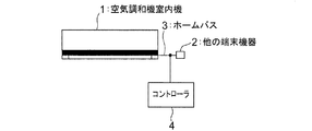
以下、本発明を図面に示す好適な実施形態に基づいて詳細に説明する。図1はHAシステムの概略構成を示す系統図であり、空気調和機室内機1と他の端末機器2とがホームバス3によって接続され、さらに、ホームバス3を介して空気調和機室内機1を含む全ての端末機器の制御及びモニタを行うコントローラ4が設けられている。これによって、家庭内機器を相互に有機的に連係するシステムが形成される。
【0010】
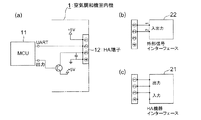
図2は本発明に係る空気調和機の第1の実施形態の概略構成である。このうち、図2(a)は空気調和機室内機1の制御及びモニタを行う入出力系統を示す結線図であり、前述したHA端子12を備えている。このHA端子12は1,2番ピンに制御信号を入力し、3,4番ピンからモニタ信号を取り出す構成になっている。空気調和機室内機1の内部においては、HA端子12の1番ピンに制御電源が接続され、2番ピンに非同期シリアル相互通信を可能にする、本発明の信号処理手段としてのUART(Universal ASynchronous Receiver and Transmitter)コントローラ11が接続されている。UARTコントローラ11の信号出力端子は、スイッチング素子の制御信号端子に接続されている。このスイッチング素子の一端は制御電源に接続され、その他端が3番ピンに接続されている。4番ピンは接地されると共に、コンデンサを介して3番ピンに接続されている。
【0011】
この空気調和機室内機1をホームバス3に接続してHAシステムを構成する場合には、図2(c)に示すように、インターフェース条件の整合性を図るHA機器インターフェース21を介してホームバス3に接続される。本実施形態は、図2(b)に示すように、HA端子12に対して、HA機器インターフェース21との接続替えが可能な外部信号インターフェース22を接続して、制御信号の送信とモニタ信号の受信とを行うものである。ここで、外部信号インターフェース22は1番ピンと2番ピンのみを使用することになる。
【0012】
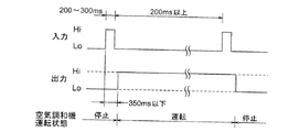
上記のように構成された本発明の第1の実施形態の動作について説明する。HA端子12には、HA機器インターフェース21が接続されたり、外部信号インターフェース22が接続されたりする。HA端子12の1,2番ピンから入力された信号が、図3に示すように、「Lo」レベルから「Hi」レベルに変化し、200〜300msecだけ経過した後に「Lo」レベルに戻るトグル動作信号である場合、UARTコントローラ11はHA機器インターフェース21を介して入力されたHAシステムの制御信号と判断し、この時点で空気調和機が停止中であれば、運転を開始し、トグル動作信号の立ち上がりから350msecを経過する前に「Lo」レベルから「Hi」レベルに変化してそのレベルを保持する運転状態信号をHA端子12の3,4番ピンに出力する。また、トグル動作信号が入力された時点で空気調和機が運転中であれば、運転を停止し、「Hi」レベルから「Lo」レベルに変化して「Lo」レベルを保持する運転状態信号をHA端子12の3,4番ピンに出力する。
【0013】
一方、UARTコントローラ11は、HA端子12の1,2番ピンからシリアル信号を受信した場合には、HA機器インターフェース21から入力されたHA信号ではなく、外部信号インターフェース22を介して入力されたHAシステム以外から受信したコマンドであると判断し、そのコマンド(エコーネットコマンド)に従って空気調和機の設定状態の変更等を行った後、運転状況を示す信号を受信信号と同じくシリアル信号を、HA端子12の1,2番ピンから送信する。
【0014】
図4は上述した動作に対応するUARTコントローラ11の具体的処理手順を示すフローチャートである。ここでは、ステップ101でHA端子12の1,2番ピンから信号入力があるか否かを判断し、信号入力があればステップ102にてシリアル信号パケットのフォーマットが一致するか否かを判定し、一致しておれぱステップ103にて入力信号を外部コマンドとして認識し、このコマンドに対応した制御を実行する。ステップ102にてシリアル信号パケットのフォーマットが一致していないと判定した場合にはステップ104にてHAシステムからの信号であるか否かを判定し、HAシステムからの信号である場合にはステップ105にてHAシステムからの信号と認識して、運転、停止の処理を実行し、HAシステムからの信号でなかったとすればステップ101の処理に戻る。
【0015】
かくして、第1の実施形態によれば、HA端子を備えた空気調和機に、UARTコントローラ11を設けて外部との相互通信を可能にすることにより、HAシステムで用いる以外の信号によって外部操作することが可能となり、また、HAシステムで用いるものと同じ信号を外部信号インターフェース22を介して入力して外部操作することもできる。
【0016】
図5は本発明に係る空気調和機の第2の実施形態として、UARTコントローラ11にその機能を持たせた具体的処理手順を示すフローチャートである。この処理は電源の投入後にHA信号以外のシリアル信号による制御コマンドを受信した以降は、全てシリアル信号での信号の入出力のみを行うようにしたものである。すなわち、ステップ111でHA端子12から信号入力があったか否かを判定し、信号入力があればステップ112で外部から入力されたコマンドであるか否かを判別し、外部コマンドであった場合にはステップ113にてこれ以降は外部コマンドのみに基づく処理を継続する。もし、ステップ112で、外部コマンドでないと判定した場合にはステップ114でHAシステムからの信号であるか否かを判定し、ここでHA信号であると判定すればステップ115にてこれ以降はHA信号のみに基づく処理を継続する。ステップ114でHA信号でないと判定した場合にはステップ111の処理に戻る。
【0017】
かくして、第2の実施形態によれば、外部との相互通信の不具合や、外部信号インターフェース22の電源が遮断された場合に、HA信号として誤検出することがなくなる。なお、外部信号インターフェース22を取り外して外部信号インターフェース22の給電が断たれた場合には、図5に示した処理によって外部コマンドのみによるか、HA信号のみによるかの再設定が行われる。
【0018】
図6は本発明に係る空気調和機の第3の実施形態として、UARTコントローラ11にその機能を持たせた具体的処理手順を示すフローチャートである。これはシリアル通信を行う外部信号インターフェース22が接続された結果をUARTコントローラ11の不揮発性のメモリーに記憶させて誤動作を防止するものである。すなわち、電源投入直後のステップ121で不揮発性メモリーを検索し、外部からのシリアル信号による通信を選択する指示データが存在するか否かを判定し、存在すればステップ122にて外部からのシリアル信号での制御を実行してステップ121の処理に戻る。ステップ121でシリアル信号による通信を選択する指示データが存在しなかった場合には、ステップ123にて外部シリアル信号入力があるか否かを判定し、外部シリアル信号の入力があれば、ステップ124にてその指示データをメモリーに記憶させ、ステップ125にて記憶させた指示データに従って制御を実行してステップ121の処理に戻る。一方、ステップ123で、外部シリアル信号入力でないと判定した場合にはステップ126でHA信号であるか否かを判定し、HA信号であると判定すればステップ127にてこれ以降はHA信号に基づく処理を実行し、ステップ121の処理に戻る。
【0019】
なお、電源投入後に、メモリーに記憶させた外部シリアル信号の制御データリセットをする必要があれば、ステップ128にてその指令を与え、ステップ129でメモリーに記憶されたデータのリセット処理を実行する。
【0020】
かくして、図6に処理手順を記した第3の実施形態によれば、外部信号インターフェース22が接続され、この外部信号インターフェース22を介して、シリアル通信による指示データを不揮発性のメモリーに記憶させるため、電源のオン、オフや外部信号インターフェース22に対する動作電力の遮断があった場合でも、誤動作を防ぐことができる。
【0021】
図7は本発明に係る空気調和機の第4の実施形態の部分構成図であり、UARTコントローラ11にHA信号で動作させるかシリアル信号で動作させるかを、制御基板に実装したスイッチSWで切り替えるようにしたもので、これによってHA機器インターフェース21又は外部信号インターフェース22の接続時にどちらの信号で動作させるかを機械的に選択させることができる。
【0022】
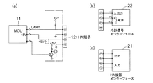
図8(a)〜(c)は本発明に係る空気調和機の第5の実施形態の概略構成図であり、図中、第1の実施形態を示す図2と同一の要素には同一の符号を付してその説明を省略する。ここに示した実施形態は、HA端子12の1番ピンをUARTコントローラ11の信号入出力端子に接続すると共に、プルアップ抵抗を介して、+5Vの制御電源に接続し、2番ピンを接地してシリアル信号の入出力を行う。UARTコントローラ11の+5V電源端子をHA端子12の3番ピンに接続する。これによって、HA端子12にHA機器インターフェース21を接続しても何等の不都合はなく、HA端子12に外部信号インターフェース22を接続したとき、HA端子12の2番ピンと3番ピンの間の電圧をそのまま外部信号インターフェース22へ供給することができる。この結果、HA端子12の2,3番ピンを外部信号インターフェース22に対する電源供給端子として使用することが可能となる。
【0023】
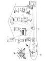
図9は本発明に係る空気調和機の第6の実施形態の概略構成図であり、前述したHA端子12に外部操作を可能にする外部信号インターフェース22を制御する際、インターフェースと外部接続機器との間をBluetoothで接続するものである。この場合、空気調和機室内機1のHA端子12には、Bluetooth通信を行うBluetooth端子13が接続され、無線にて送受信するようになっている。この空気調和機室内機1を含む複数の端末機器2の制御及びモニタするためにコントローラとしてのホーム端末制御部5を備え、このホーム端末制御部5が外部のインターネット30に接続されている。Bluetoothは外部インターフェースとその制御機器間を2.4GHz帯域を用いる無線伝送方式である。これによって、家庭内に設置される空気調和機と外部操作する制御装置との間を無線で送受信することとなり、家庭内の端末機器2に対する配線工事が不要化され、設置工事の簡素化が図られる。
【0024】
図10は上述したBluetoothによる制御システムの概略を示す説明図であり、ASP(Apple Talk Transaction Protocol)サービス機構40が、ISP(国際標準化プロファイル)と呼ばれる仕様のインターネット30に接続され、このインターネット30に前述したホーム端末制御部5が接続されている。このホーム端末制御部5と、空気調和機室内機1を含む多数の端末機器とがBluetooth端子13により無線にて送受信するように構成されている。
【0025】
図11はシリアル通信でやりとりされる制御コマンドをエコーネットオブジェクトに設定した場合の基本電文形式を示し、図12はオブジェクト(SEOJ,DEOJ)が家庭用エアコンに規定されているときのプロパティの一部を示している。すなわち、エコーネットの電文形式にのっとり、家庭用エアコンクラスのプロパティとデータをシリアル通信でやりとりするようになっている。ここに示されているコマンドは一般に公開されているコマンド体系であるため、他製品との互換性が保たれるようになっている。
【0026】
かくして、図9乃至図12を用いて説明した第6の実施形態によれば、「ECHONET」や「ECHONET on Bluetooth」等のプロトコルを用いて遠隔操作を行う場合の高価なマイクロコンピュータや制御回路がインターネット30に含まれているため、空気調和機毎にこれら高価な要素を設ける必要がなく、従って、HA端子12の共用化による制御基板のコンパクト化、及び制御基板の共用化が可能となる。
【0027】
【発明の効果】
以上の説明によって明らかなように、本発明によれば、従来の機種にも共用することができ、かつ、安価で、複数の遠隔操作機能を持たせ得る空気調和機及びインターフェースを提供することができる。
【図面の簡単な説明】
【図1】 一般的なHAシステムの概略構成を示す系統図。
【図2】 図2は本発明に係る空気調和機の第1の実施形態の概略構成図。
【図3】 第1の実施形態の動作を説明するためのタイムチャート。
【図4】 第1の実施形態を構成するUARTコントローラの具体的処理手順を示すフローチャート。
【図5】 本発明に係る空気調和機の第2の実施形態として、UARTコントローラにその機能を持たせた具体的処理手順を示すフローチャート。
【図6】 本発明に係る空気調和機の第3の実施形態として、UARTコントローラにその機能を持たせた具体的処理手順を示すフローチャート。
【図7】 図7は本発明に係る空気調和機の第4の実施形態の部分構成図。
【図8】 本発明に係る空気調和機の第5の実施形態の概略構成図。
【図9】 本発明に係る空気調和機の第6の実施形態の概略構成図。
【図10】 第6の実施形態に関連する制御システムの概略を示す説明図。
【図11】 第6の実施形態に関連してシリアル通信でやりとりされる制御コマンドをエコーネットオブジェクトに設定した場合の基本電文形式。
【図12】 第6の実施形態に関連してオブジェクトが家庭用エアコンに規定されているときのプロパティを示した図。
【符号の説明】
1 空気調和機室内機
2 他の端末機器
3 ホームバス
4 コントローラ
5 ホーム端末制御部
11 UARTコントローラ
12 HA端子
13 Bluetooth端子
21 HA機器インターフェース
22 外部信号インターフェース
30 インターネット
SW スイッチ[0001]
BACKGROUND OF THE INVENTION
The present invention relates to an air conditioner and an interface provided with a home automation terminal (hereinafter, abbreviated as HA) for transmitting a control signal and a monitor signal.
[0002]
[Prior art]
Designing and manufacturing a dedicated adapter for remotely operating the air conditioner from the outside using a telephone or the like increases the development cost and complicates the manufacturing process and inventory management. Thus, as a simple method, it is considered to use an HA terminal (JEM-A) defined in the Japan Electrical Manufacturers' Association standard. This HA terminal is a terminal provided for connection to an interface unit (IFU) interposed between the terminal device and the home bus in constructing the HA system. Since this HA terminal has the 1st and 2nd pins (terminal) for the control signal and the 3rd and 4th pins for the monitor signal, it commands the operation and stop of the air conditioner using the 1st and 2nd pins. The state can be monitored using the third and fourth pins.
[0003]
As another method, an HA system is constructed using an interface unit, and “ECHONET” and “ECHONET on Bluetooth” are proposed as remote control methods using this HA system, which are compared with conventional HA input / output control. As a result, more advanced remote control has been studied.
[0004]
[Problems to be solved by the invention]
Among the remote controls described above, the method using the HA terminal without constructing the HA system can only have the function of operating and stopping the air conditioner and the monitoring function thereof, so that the operation mode, room temperature, air volume An operation corresponding to a remote control device capable of setting such as could not be performed.
[0005]
On the other hand, when an HA system is constructed and remote control is performed using a protocol such as “ECHONET” or “ECHONET on Bluetooth”, an expensive microcomputer or control circuit is required because the control protocol is sophisticated and complicated. In addition, a terminal for receiving a remote operation signal from the outside must be provided separately, and there is a problem that the control board becomes larger by the provision of this terminal.
[0006]
The present invention has been made to solve the above-described problems, and provides an air conditioner and an interface that can be shared with conventional models and that can be provided with a plurality of remote control functions at low cost. For the purpose.
[0007]
[Means for Solving the Problems]
An air conditioner according to a first aspect of the present invention is an air conditioner comprising four terminals including a control power supply terminal and a ground terminal, and having an HA terminal for transmitting a control signal and a monitor signal. Signal processing means for enabling communication with a signal other than that used in the HA system with the connected interface is provided, and external operation is performed by signals other than those used in the HA system with the interface by this signal processing means. The interface driving power is supplied from between the control power supply terminal and the ground terminal.
[0008]
The interface of the invention according to
[0009]
DETAILED DESCRIPTION OF THE INVENTION
Hereinafter, the present invention will be described in detail based on preferred embodiments shown in the drawings. FIG. 1 is a system diagram showing a schematic configuration of an HA system, in which an air conditioner
[0010]
FIG. 2 is a schematic configuration of the first embodiment of the air conditioner according to the present invention. 2A is a connection diagram showing an input / output system for controlling and monitoring the air conditioner
[0011]
When the HA system is configured by connecting the air conditioner
[0012]
The operation of the first embodiment of the present invention configured as described above will be described. An
[0013]
On the other hand, when the
[0014]
FIG. 4 is a flowchart showing a specific processing procedure of the
[0015]
Thus, according to the first embodiment, the air conditioner provided with the HA terminal is provided with the
[0016]
FIG. 5 is a flowchart showing a specific processing procedure for giving the function to the
[0017]
Thus, according to the second embodiment, there is no possibility of erroneous detection as an HA signal when there is a malfunction in mutual communication with the outside or when the power supply of the
[0018]
FIG. 6 is a flowchart showing a specific processing procedure for giving the function to the
[0019]
If it is necessary to reset the control data of the external serial signal stored in the memory after the power is turned on, the command is given in
[0020]
Thus, according to the third embodiment whose processing procedure is shown in FIG. 6, the
[0021]
FIG. 7 is a partial configuration diagram of the fourth embodiment of the air conditioner according to the present invention, in which the
[0022]
FIGS. 8A to 8C are schematic configuration diagrams of the fifth embodiment of the air conditioner according to the present invention, in which the same elements as those in FIG. 2 showing the first embodiment are the same. Reference numerals are assigned and explanations thereof are omitted. In the embodiment shown here, the 1st pin of the
[0023]
FIG. 9 is a schematic configuration diagram of a sixth embodiment of an air conditioner according to the present invention. When controlling the
[0024]
FIG. 10 is an explanatory diagram showing an outline of the above-described control system based on Bluetooth. An ASP (Apple Talk Transaction Protocol)
[0025]
FIG. 11 shows a basic message format when a control command exchanged by serial communication is set in an echo net object, and FIG. 12 shows a part of properties when an object (SEOJ, DEOJ) is defined in a home air conditioner. Is shown. In other words, according to the Echonet message format, properties and data of the home air conditioner class are exchanged via serial communication. Since the command shown here is a publicly available command system, compatibility with other products is maintained.
[0026]
Thus, according to the sixth embodiment described with reference to FIGS. 9 to 12, an expensive microcomputer or control circuit for remote control using a protocol such as “ECHONET” or “ECHONET on Bluetooth” is provided. Since it is included in the
[0027]
【The invention's effect】
As is apparent from the above description, according to the present invention, it is possible to provide an air conditioner and an interface that can be shared with conventional models and can be provided with a plurality of remote operation functions at low cost. it can.
[Brief description of the drawings]
FIG. 1 is a system diagram showing a schematic configuration of a general HA system.
FIG. 2 is a schematic configuration diagram of a first embodiment of an air conditioner according to the present invention.
FIG. 3 is a time chart for explaining the operation of the first embodiment;
FIG. 4 is a flowchart showing a specific processing procedure of a UART controller constituting the first embodiment.
FIG. 5 is a flowchart showing a specific processing procedure in which a UART controller has the function as the second embodiment of the air conditioner according to the present invention.
FIG. 6 is a flowchart showing a specific processing procedure for giving a function to a UART controller as a third embodiment of the air conditioner according to the present invention.
FIG. 7 is a partial configuration diagram of a fourth embodiment of an air conditioner according to the present invention.
FIG. 8 is a schematic configuration diagram of a fifth embodiment of an air conditioner according to the present invention.
FIG. 9 is a schematic configuration diagram of a sixth embodiment of an air conditioner according to the present invention.
FIG. 10 is an explanatory diagram showing an outline of a control system related to the sixth embodiment.
FIG. 11 is a basic message format when a control command exchanged by serial communication in relation to the sixth embodiment is set in an echo net object.
FIG. 12 is a view showing properties when an object is defined in a home air conditioner in relation to the sixth embodiment.
[Explanation of symbols]
DESCRIPTION OF
Claims (2)
前記HA端子に接続されたインターフェースとの間でHAシステムで用いる以外の信号での通信を可能にする信号処理手段を備え、この信号処理手段によって前記インターフェースとの間でHAシステムで用いる以外の信号により外部操作を可能にするとともに、前記インターフェースの駆動電力を前記制御電源端子と前記接地端子間から供給することを特徴とする空気調和機。 In an air conditioner comprising four terminals including a control power supply terminal and a ground terminal, and having an HA terminal for transmitting a control signal and a monitor signal,
A signal processing means for enabling communication with a signal other than for use in HA system between the HA interface connected to the terminal, signals other than that used in the HA system between said interface by the signal processing means The air conditioner is characterized in that it enables external operation and supplies driving power for the interface from between the control power supply terminal and the ground terminal .
Priority Applications (1)
| Application Number | Priority Date | Filing Date | Title |
|---|---|---|---|
| JP2002180233A JP4099352B2 (en) | 2002-06-20 | 2002-06-20 | Air conditioner and interface |
Applications Claiming Priority (1)
| Application Number | Priority Date | Filing Date | Title |
|---|---|---|---|
| JP2002180233A JP4099352B2 (en) | 2002-06-20 | 2002-06-20 | Air conditioner and interface |
Related Child Applications (1)
| Application Number | Title | Priority Date | Filing Date |
|---|---|---|---|
| JP2007214053A Division JP4467607B2 (en) | 2007-08-20 | 2007-08-20 | Air conditioner |
Publications (3)
| Publication Number | Publication Date |
|---|---|
| JP2004020163A JP2004020163A (en) | 2004-01-22 |
| JP2004020163A5 JP2004020163A5 (en) | 2005-08-11 |
| JP4099352B2 true JP4099352B2 (en) | 2008-06-11 |
Family
ID=31177422
Family Applications (1)
| Application Number | Title | Priority Date | Filing Date |
|---|---|---|---|
| JP2002180233A Expired - Lifetime JP4099352B2 (en) | 2002-06-20 | 2002-06-20 | Air conditioner and interface |
Country Status (1)
| Country | Link |
|---|---|
| JP (1) | JP4099352B2 (en) |
Families Citing this family (2)
| Publication number | Priority date | Publication date | Assignee | Title |
|---|---|---|---|---|
| CN107770021B (en) * | 2017-10-11 | 2019-10-29 | 青岛海信日立空调系统有限公司 | Home bus system HBS circuit, signal conversion method and device |
| JP7344777B2 (en) * | 2019-11-27 | 2023-09-14 | 東芝キヤリア株式会社 | air conditioner |
-
2002
- 2002-06-20 JP JP2002180233A patent/JP4099352B2/en not_active Expired - Lifetime
Also Published As
| Publication number | Publication date |
|---|---|
| JP2004020163A (en) | 2004-01-22 |
Similar Documents
| Publication | Publication Date | Title |
|---|---|---|
| US20040139210A1 (en) | Home network system and method for operating the same | |
| JP3127347U (en) | Programmable logic controller with power frequency carrier | |
| EP1657639A1 (en) | Outdoor-unit software upgrade system and method | |
| WO2004097557A2 (en) | Distributed control systems and methods | |
| WO2002015473A2 (en) | In circuit serial programming of default configuration | |
| US8484323B2 (en) | Network system connected with multiple master devices and method for operating the same | |
| JP2013537653A (en) | Docking station with redundant communication path | |
| JP2004135351A (en) | Random number generating home network system and its control method | |
| WO2022127087A1 (en) | Connection and control board for air conditioning system, air conditioning system, and adaptive control method | |
| JP2001156872A (en) | Communication protocol conversion system and monitor | |
| JP4467607B2 (en) | Air conditioner | |
| JP4099352B2 (en) | Air conditioner and interface | |
| CN101163039A (en) | Apparatus for restoring network information for home network system and method thereof | |
| EP3873117B1 (en) | Device configuration | |
| KR20050068297A (en) | Remote control system and method for controlling of the same | |
| JP4950617B2 (en) | Air conditioning management apparatus, air conditioning management method, and air conditioning management program | |
| WO2002015517A2 (en) | Remote configuration of network node via controller area network messages | |
| CN111030722B (en) | Communication circuit and communication method for battery management system | |
| JP2001156728A (en) | Electronic device and method for outputting operating state of electronic device | |
| KR100386598B1 (en) | apparatus and method of setting communication packet for remote control between device and device | |
| JP3882618B2 (en) | Communication apparatus and network system | |
| JP2005073055A (en) | Network adapter and household electrical appliance connectable to network adapter | |
| JPH11337156A (en) | Device and method for controlling air conditioner | |
| TWI392191B (en) | Remote control of the power supply system | |
| JP2006229422A (en) | Electrical equipment and communication adapter capable of being connected to electrical equipment |
Legal Events
| Date | Code | Title | Description |
|---|---|---|---|
| A521 | Request for written amendment filed |
Free format text: JAPANESE INTERMEDIATE CODE: A523 Effective date: 20050125 |
|
| A621 | Written request for application examination |
Free format text: JAPANESE INTERMEDIATE CODE: A621 Effective date: 20050125 |
|
| A977 | Report on retrieval |
Free format text: JAPANESE INTERMEDIATE CODE: A971007 Effective date: 20070615 |
|
| A131 | Notification of reasons for refusal |
Free format text: JAPANESE INTERMEDIATE CODE: A131 Effective date: 20070619 |
|
| A521 | Request for written amendment filed |
Free format text: JAPANESE INTERMEDIATE CODE: A523 Effective date: 20070820 |
|
| TRDD | Decision of grant or rejection written | ||
| A01 | Written decision to grant a patent or to grant a registration (utility model) |
Free format text: JAPANESE INTERMEDIATE CODE: A01 Effective date: 20080311 |
|
| A01 | Written decision to grant a patent or to grant a registration (utility model) |
Free format text: JAPANESE INTERMEDIATE CODE: A01 |
|
| A61 | First payment of annual fees (during grant procedure) |
Free format text: JAPANESE INTERMEDIATE CODE: A61 Effective date: 20080317 |
|
| R150 | Certificate of patent or registration of utility model |
Free format text: JAPANESE INTERMEDIATE CODE: R150 Ref document number: 4099352 Country of ref document: JP Free format text: JAPANESE INTERMEDIATE CODE: R150 |
|
| FPAY | Renewal fee payment (event date is renewal date of database) |
Free format text: PAYMENT UNTIL: 20110321 Year of fee payment: 3 |
|
| S111 | Request for change of ownership or part of ownership |
Free format text: JAPANESE INTERMEDIATE CODE: R313111 |
|
| R350 | Written notification of registration of transfer |
Free format text: JAPANESE INTERMEDIATE CODE: R350 |
|
| FPAY | Renewal fee payment (event date is renewal date of database) |
Free format text: PAYMENT UNTIL: 20110321 Year of fee payment: 3 |
|
| FPAY | Renewal fee payment (event date is renewal date of database) |
Free format text: PAYMENT UNTIL: 20110321 Year of fee payment: 3 |
|
| FPAY | Renewal fee payment (event date is renewal date of database) |
Free format text: PAYMENT UNTIL: 20120321 Year of fee payment: 4 |
|
| FPAY | Renewal fee payment (event date is renewal date of database) |
Free format text: PAYMENT UNTIL: 20120321 Year of fee payment: 4 |
|
| FPAY | Renewal fee payment (event date is renewal date of database) |
Free format text: PAYMENT UNTIL: 20130321 Year of fee payment: 5 |
|
| FPAY | Renewal fee payment (event date is renewal date of database) |
Free format text: PAYMENT UNTIL: 20130321 Year of fee payment: 5 |
|
| R250 | Receipt of annual fees |
Free format text: JAPANESE INTERMEDIATE CODE: R250 |
|
| R250 | Receipt of annual fees |
Free format text: JAPANESE INTERMEDIATE CODE: R250 |
|
| R250 | Receipt of annual fees |
Free format text: JAPANESE INTERMEDIATE CODE: R250 |
|
| R250 | Receipt of annual fees |
Free format text: JAPANESE INTERMEDIATE CODE: R250 |
|
| EXPY | Cancellation because of completion of term |