JP4098422B2 - Switch device - Google Patents
Switch device Download PDFInfo
- Publication number
- JP4098422B2 JP4098422B2 JP32514298A JP32514298A JP4098422B2 JP 4098422 B2 JP4098422 B2 JP 4098422B2 JP 32514298 A JP32514298 A JP 32514298A JP 32514298 A JP32514298 A JP 32514298A JP 4098422 B2 JP4098422 B2 JP 4098422B2
- Authority
- JP
- Japan
- Prior art keywords
- lock pin
- cam groove
- operation member
- switch
- spring
- Prior art date
- Legal status (The legal status is an assumption and is not a legal conclusion. Google has not performed a legal analysis and makes no representation as to the accuracy of the status listed.)
- Expired - Fee Related
Links
Images


Description
【0001】
【発明の属する技術分野】
本発明は、ロックピンの先端部をカム溝の底部側に付勢する押えばねを備えたスイッチ装置に関する。
【0002】
【発明が解決しようとする課題】
プッシュロック式のスイッチ装置においては、次のような構成のものがある。すなわち、スイッチベースに往復移動可能に設けられた操作部材を、復帰用ばねにより原位置方向に付勢して設ける。そして、操作部材とスイッチベースのうちの一方、例えばスイッチベースに、ほぼV字形の係合部を有するカム溝を設け、また、カム溝を設けた方とは反対側の操作部材に、ロックピンの基端部を取り付けると共に、そのロックピンの先端部を上記カム溝の底部側に付勢する棒状の押えばねを設ける。
【0003】
この構成において、原位置にある操作部材を、復帰用ばねの付勢力に抗して押圧操作すると、操作部材が同方向へ移動すると共に、ロックピンの先端部がカム溝に沿って摺動し、そして、操作部材に対する押圧力を解除すると、ロックピンの先端部がカム溝の係合部に係合することにより操作部材が作用位置に保持される。この後、操作部材を再度押圧操作すると、ロックピンの先端部の係合部に対する係合が外れ、操作部材に対する押圧力を解除すると、復帰用ばねの付勢力により操作部材が原位置に復帰されると共に、ロックピンの先端部がカム溝に沿って摺動し、元の位置に戻る。
【0004】
ところで、このような構成のものでは、操作部材の操作時に、ロックピンの先端部は、カム溝において段差を飛び越すように落ちたり、斜面を摺動したりするため、カム溝の深さ方向にも動く。このため、そのロックピンの動きに伴い、そのロックピンの先端部をカム溝の底部側に付勢する押えばねが振動し、これらロックピンと押えばねとの間で音が発生する。この場合、特に、それらロックピンと押えばねは共に金属製であるため、それらの間で発生する音が金属音で、耳障りになるという問題点があった。
【0005】
本発明は上記した事情に鑑みてなされたものであり、その目的は、操作部材の操作時において、ロックピンと押えばねとの間で発生する音を低減できるスイッチ装置を提供するにある。
【0006】
【課題を解決するための手段】
上記の目的を達成するために、本発明は、スイッチベースに往復移動可能に設けられ、押圧操作される操作部材と、この操作部材に原位置方向への復帰力を付与する復帰用ばねと、前記スイッチベース及び操作部材のうちの一方に設けられ、ほぼV字形の係合部を有するカム溝と、前記スイッチベース及び操作部材のうち前記カム溝が設けられた方とは反対側の部材に基端部が取り付けられ、前記操作部材の移動に基づき先端部が前記カム溝に沿って相対的に移動すると共に、その先端部が前記係合部に係合することにより前記操作部材を作用位置に保持するロックピンと、このロックピンの先端部を前記カム溝の底部側に付勢するように設けられた押えばねと、前記操作部材の移動に応じて状態が切り替えられるスイッチとを具備したスイッチ装置において、
前記押えばねの両端部に振動吸収部材を設けて、これら各振動吸収部材を、前記ロックピンの基端部が取り付けられた側の部材に形成された収容部に嵌合させることにより、前記押えばねを前記ロックピンの基端部が取り付けられた側の部材に取り付ける構成としたことを特徴としている。
【0007】
上記した手段によれば、操作部材の操作時において、ロックピンの先端部の動きに伴い押えばねが振動するが、その振動が振動吸収部材により吸収されるようになるので、ロックピンとその押えばねとの間で発生する音を低減できるようになる。
【0008】
【発明の実施の形態】
以下、本発明の一実施例について、図面を参照して説明する。
図2には、プッシュロック式のスイッチ装置の断面図が示されており、この図2において、筒状をなすスイッチケース1にインシュレータ2が固定状態に設けられており、これらスイッチケース1とインシュレータ2とからスイッチベース3が構成されている。
【0009】
このスイッチベース3内に、操作部材4が図2中、上下方向に往復移動可能に配設されている。この操作部材4とスイッチケース1との間には、圧縮コイルばねからなる復帰用ばね5が配設されていて、この復帰用ばね5の付勢力により、操作部材4は原位置方向である図2中矢印A方向に付勢されている。操作部材4の図2中、上部にはカバー6が取り付けられている。
【0010】
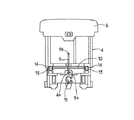
上記スイッチベース3のインシュレータ2と操作部材4との間には、ロック機構7が設けられている。このロック機構7は、図1にも示すように、インシュレータ2において操作部材4と対向する面に設けられたカム溝8と、基端部9aが操作部材4に取り付けられたロックピン9と、このロックピン9の先端部9bをカム溝8の底部側に付勢するように操作部材4に設けられた棒状の押えばね10とから構成されている。
【0011】
このうち、カム溝8には、図1及び図4に示すように、中央部にハート形の凸部11が形成されていて、その凸部11に、ほぼV字形の係合部12が形成されている。また、カム溝8の底部には段差8aや斜面8bが形成されている。上記ロックピン9は、クランク状をなしていて、その基端部9aを操作部材4に形成された取付孔4aに挿入することにより、操作部材4に取り付けられている。ロックピン9の先端部9bは、カム溝8側に向けられていて、そのカム溝8に沿って摺動するようになっている。
【0012】
棒状の押えばね10の両端部には、例えばゴム製のさいころ状をなす振動吸収部材13が設けられていて、押えばね10は、これら各振動吸収部材13を操作部材4に形成された収容部14に嵌合させることにより、操作部材4に取り付けられている。この場合、振動吸収部材13は、押えばね10に対して成形により設けられている。そして、操作部材4をスイッチベース3内に組み込んだ状態で、押えばね10がロックピン9をカム溝8側へ押えることにより、ロックピン9の先端部9bをカム溝8の底部側に付勢している。
【0013】
操作部材4において、ロックピン9の図2中、下方にはばね収容部15が形成されていて、可動接点16が、そのばね収容部15に収容された圧縮コイルばねからなるばね部材17によりインシュレータ2側に付勢して設けられている。インシュレータ2において上記可動接点16が摺動する面には、その可動接点16が接離する固定接点18が設けられている。これら可動接点16と固定接点18とによりスイッチ19を構成している。
【0014】
次に、上記構成の作用を説明する。
図2は操作部材4が原位置にある状態が示されており、この状態では、可動接点16が固定接点18から離間していて、スイッチ19はオフ状態となっている。この図2の状態から、操作部材4を復帰用ばね5の付勢力に抗して矢印Aとは反対方向へ押圧操作すると、操作部材4が同方向へ移動すると共に、ロックピン9の先端部9bがカム溝8に沿って摺動する(図4の矢印B1参照)。
【0015】
そして、操作部材4に対する押圧力を解除すると、操作部材4が矢印A方向に戻りながら、ロックピン9の先端部9bがカム溝8の係合部12に係合し(図4の矢印B2参照)、これにより操作部材4が作用位置に保持されるようになる。このとき、可動接点16が固定接点18に接触し、スイッチ19はオン状態となる。
【0016】
この後、操作部材4を矢印Aとは反対方向へ再度押圧操作すると、操作部材4が同方向へ移動しながらロックピン9の先端部9bの係合部12に対する係合が外れる(図4の矢印B3参照)。そして、操作部材4に対する押圧力を解除すると、復帰用ばね5の付勢力により操作部材4が原位置に復帰されると共に、ロックピン9の先端部9bがカム溝8に沿って摺動し、元の位置に戻る(図4の矢印B4参照)。これに伴い、可動接点16が固定接点18から離間し、スイッチ19はオフ状態となる。
【0017】
ここで、操作部材4の操作時に、ロックピン9の先端部9bがカム溝8の底部に沿って摺動するが、このとき、ロックピン9の先端部9bは、カム溝8の段差8aを飛び越すように落ちたり、斜面8bを摺動したりするため、カム溝8の深さ方向にも動く。このため、そのロックピン9の動きに伴い、そのロックピン9の先端部9bをカム溝8の底部側に付勢する押えばね10が振動し、これらロックピン9と押えばね10との間で音が発生することになる。
【0018】
しかしながら、本実施例においては、押えばね10の両端部に振動吸収部材13を設けていて、これら両振動吸収部材13が操作部材4に固定されているので、押えばね10の振動がそれら両振動吸収部材13により吸収され、ロックピン9とその押えばね10との間で発生する音を低減できるようになる。
【0019】
本発明は、上記した実施例にのみ限定されるものではなく、次のように変形または拡張することができる。
上記した実施例では、カム溝8を固定側のインシュレータ2に設けると共に、ロックピン9及び押えばね10を可動側の操作部材4に設けた例を示したが、カム溝8を可動側の操作部材4に設けると共に、ロックピン9及び押えばね10を固定側のインシュレータ2に設ける構成とすることもできる。
【0020】
【発明の効果】
以上の説明から明らかなように、本発明によれば、操作部材の操作時において、ロックピンの先端部の動きに伴い押えばねが振動するが、その振動を振動吸収部材により吸収できるようになるので、ロックピンとその押えばねとの間で発生する音を低減できるようになる。
【図面の簡単な説明】
【図1】本発明の一実施例を示す要部の斜視図
【図2】スイッチ装置全体の縦断面図
【図3】操作部材にロックピンと押えばねを組み付けた状態での正面図
【図4】ロックピンの先端部の動きを説明するためのカム溝部分の平面図
【符号の説明】
1はスイッチケース、2はインシュレータ、3はスイッチベース、4は操作部材、5は復帰用ばね、7はロック機構、8はカム溝、9はロックピン、9aは基端部、9bは先端部、10は押えばね、12は係合部、13は振動吸収部材、14は収容部、16は可動接点、18は固定接点、19はスイッチを示す。[0001]
BACKGROUND OF THE INVENTION
The present invention relates to a switch device including a presser spring that urges a tip end portion of a lock pin toward a bottom side of a cam groove.
[0002]
[Problems to be solved by the invention]
Some push-lock type switch devices have the following configuration. That is, the operating member provided on the switch base so as to be reciprocally movable is urged in the original position direction by the return spring. A cam groove having a substantially V-shaped engaging portion is provided on one of the operation member and the switch base, for example, the switch base, and a lock pin is provided on the operation member on the opposite side of the cam groove. And a bar-shaped presser spring that urges the distal end of the lock pin toward the bottom of the cam groove.
[0003]
In this configuration, when the operating member in the original position is pressed against the urging force of the return spring, the operating member moves in the same direction and the tip of the lock pin slides along the cam groove. And if the pressing force with respect to an operation member is cancelled | released, the operation member will be hold | maintained in an action position because the front-end | tip part of a lock pin engages with the engaging part of a cam groove. After that, when the operation member is pressed again, the engagement of the distal end portion of the lock pin with the engaging portion is released, and when the pressing force against the operation member is released, the operation member is returned to the original position by the urging force of the return spring. At the same time, the tip of the lock pin slides along the cam groove and returns to the original position.
[0004]
By the way, in such a configuration, when the operation member is operated, the tip of the lock pin falls so as to jump over the step in the cam groove or slides on the inclined surface. Also moves. For this reason, with the movement of the lock pin, the presser spring that urges the tip of the lock pin toward the bottom side of the cam groove vibrates, and a sound is generated between the lock pin and the presser spring. In this case, in particular, since both the lock pin and the presser spring are made of metal, there is a problem in that the sound generated between them is a metal sound and becomes annoying.
[0005]
The present invention has been made in view of the above circumstances, and an object of the present invention is to provide a switch device that can reduce a sound generated between a lock pin and a presser spring when an operation member is operated.
[0006]
[Means for Solving the Problems]
In order to achieve the above object, the present invention provides an operation member that is provided on the switch base so as to be reciprocally movable and is pressed, and a return spring that applies a return force to the operation member in the original position direction. A cam groove provided on one of the switch base and the operation member and having a substantially V-shaped engaging portion, and a member on the opposite side of the switch base and the operation member on which the cam groove is provided. A proximal end portion is attached, and the distal end portion relatively moves along the cam groove based on the movement of the operation member, and the distal end portion engages with the engagement portion, thereby moving the operation member to the working position. A lock pin that is held by the switch, a presser spring that is provided so as to urge the tip of the lock pin toward the bottom of the cam groove, and a switch that can be switched in accordance with the movement of the operation member. In Ji device,
A vibration absorbing member is provided at both ends of the presser spring , and each of the vibration absorbing members is fitted into a receiving portion formed on a member on the side to which the base end of the lock pin is attached. The spring is configured to be attached to a member on the side to which the base end portion of the lock pin is attached .
[0007]
According to the above-described means, when the operating member is operated, the presser spring vibrates with the movement of the tip end portion of the lock pin. However, the vibration is absorbed by the vibration absorbing member. Sound generated between and can be reduced.
[0008]
DETAILED DESCRIPTION OF THE INVENTION
An embodiment of the present invention will be described below with reference to the drawings.
FIG. 2 is a cross-sectional view of a push-lock type switch device. In FIG. 2, an
[0009]
An operation member 4 is disposed in the switch base 3 so as to be reciprocally movable in the vertical direction in FIG. Between the operation member 4 and the
[0010]
A
[0011]
Among these, as shown in FIGS. 1 and 4, the
[0012]
At both ends of the rod-
[0013]
In the operation member 4, a
[0014]
Next, the operation of the above configuration will be described.
FIG. 2 shows a state in which the operation member 4 is in the original position. In this state, the
[0015]
When the pressing force on the operation member 4 is released, the
[0016]
Thereafter, when the operating member 4 is pressed again in the direction opposite to the arrow A, the operating member 4 moves in the same direction, and the engagement of the
[0017]
Here, when the operation member 4 is operated, the
[0018]
However, in the present embodiment, the
[0019]
The present invention is not limited to the embodiments described above, and can be modified or expanded as follows.
In the embodiment described above, the
[0020]
【The invention's effect】
As is apparent from the above description, according to the present invention, the presser spring vibrates with the movement of the distal end portion of the lock pin during operation of the operating member, but the vibration can be absorbed by the vibration absorbing member. Therefore, it is possible to reduce the sound generated between the lock pin and the presser spring.
[Brief description of the drawings]
FIG. 1 is a perspective view of an essential part showing an embodiment of the present invention. FIG. 2 is a longitudinal sectional view of the entire switch device. FIG. 3 is a front view in a state where a lock pin and a presser spring are assembled to an operation member. ] Plan view of cam groove for explaining movement of tip of lock pin [Explanation of symbols]
1 is a switch case, 2 is an insulator, 3 is a switch base, 4 is an operation member, 5 is a return spring, 7 is a lock mechanism, 8 is a cam groove, 9 is a lock pin, 9a is a proximal end, and 9b is a distal end.
Claims (1)
この操作部材に原位置方向への復帰力を付与する復帰用ばねと、
前記スイッチベース及び操作部材のうちの一方に設けられ、ほぼV字形の係合部を有するカム溝と、
前記スイッチベース及び操作部材のうち前記カム溝が設けられた方とは反対側の部材に基端部が取り付けられ、前記操作部材の移動に基づき先端部が前記カム溝に沿って相対的に移動すると共に、その先端部が前記係合部に係合することにより前記操作部材を作用位置に保持するロックピンと、
このロックピンの先端部を前記カム溝の底部側に付勢するように設けられた押えばねと、
前記操作部材の移動に応じて状態が切り替えられるスイッチとを具備したスイッチ装置において、
前記押えばねの両端部に振動吸収部材を設けて、これら各振動吸収部材を、前記ロックピンの基端部が取り付けられた側の部材に形成された収容部に嵌合させることにより、前記押えばねを前記ロックピンの基端部が取り付けられた側の部材に取り付ける構成としたことを特徴とするスイッチ装置。An operation member provided on the switch base so as to be reciprocally movable and operated to be pressed;
A return spring for applying a return force in the original position direction to the operating member;
A cam groove provided on one of the switch base and the operating member and having a substantially V-shaped engaging portion;
A base end portion is attached to a member on the opposite side of the switch base and the operation member from the one provided with the cam groove, and a distal end portion relatively moves along the cam groove based on the movement of the operation member. And a lock pin that holds the operating member in the operating position by engaging the tip of the engaging portion with the engaging portion;
A presser spring provided to urge the tip of the lock pin toward the bottom side of the cam groove;
In a switch device comprising a switch whose state is switched according to the movement of the operation member,
A vibration absorbing member is provided at both ends of the presser spring , and each of the vibration absorbing members is fitted into a receiving portion formed on a member on the side to which the base end of the lock pin is attached. A switch device characterized in that a spring is attached to a member on a side to which a base end portion of the lock pin is attached .
Priority Applications (1)
| Application Number | Priority Date | Filing Date | Title |
|---|---|---|---|
| JP32514298A JP4098422B2 (en) | 1998-11-16 | 1998-11-16 | Switch device |
Applications Claiming Priority (1)
| Application Number | Priority Date | Filing Date | Title |
|---|---|---|---|
| JP32514298A JP4098422B2 (en) | 1998-11-16 | 1998-11-16 | Switch device |
Publications (2)
| Publication Number | Publication Date |
|---|---|
| JP2000149710A JP2000149710A (en) | 2000-05-30 |
| JP4098422B2 true JP4098422B2 (en) | 2008-06-11 |
Family
ID=18173528
Family Applications (1)
| Application Number | Title | Priority Date | Filing Date |
|---|---|---|---|
| JP32514298A Expired - Fee Related JP4098422B2 (en) | 1998-11-16 | 1998-11-16 | Switch device |
Country Status (1)
| Country | Link |
|---|---|
| JP (1) | JP4098422B2 (en) |
Families Citing this family (3)
| Publication number | Priority date | Publication date | Assignee | Title |
|---|---|---|---|---|
| JP4747661B2 (en) * | 2005-04-28 | 2011-08-17 | ソニー株式会社 | Display stand |
| JP2013118059A (en) * | 2011-12-01 | 2013-06-13 | Omron Corp | Cam groove structure and switch with the same |
| KR101538275B1 (en) * | 2014-11-18 | 2015-07-22 | 천광주 | Slide type writing tools having push lock system |
-
1998
- 1998-11-16 JP JP32514298A patent/JP4098422B2/en not_active Expired - Fee Related
Also Published As
| Publication number | Publication date |
|---|---|
| JP2000149710A (en) | 2000-05-30 |
Similar Documents
| Publication | Publication Date | Title |
|---|---|---|
| US3582592A (en) | Pushbutton switches | |
| JP3202515B2 (en) | Push lock switch | |
| EP1310968A2 (en) | Switch apparatus | |
| JP4098422B2 (en) | Switch device | |
| JPS58163115A (en) | Switch | |
| JP3820680B2 (en) | Push switch and assembling method thereof | |
| US5875887A (en) | Contact switch assembly having a conductor that holds a movable contact plate | |
| JP3956806B2 (en) | Push button switch | |
| JP3980915B2 (en) | Switch device | |
| CA1148997A (en) | Vibration-preventing feature for use in a push-button switch assembly | |
| JPH0753230Y2 (en) | Switch device | |
| JPH0733326Y2 (en) | Switch device | |
| JP3921721B2 (en) | Push switch | |
| JP2004327115A (en) | Switch | |
| JP2642493B2 (en) | Push-type electric component and method of mounting coil spring on push-type electric component | |
| JP2615793B2 (en) | switch | |
| USRE27963E (en) | Pushbutton switches | |
| JP2571575Y2 (en) | Switch device | |
| KR200153716Y1 (en) | A structure for actuating a power switch in monitor | |
| KR930006816Y1 (en) | Push-button switch | |
| JP3621238B2 (en) | Push switch | |
| JPH04501Y2 (en) | ||
| KR830000035Y1 (en) | Push pull switch | |
| JP3036265U (en) | Switch operation button holding structure | |
| JPH07134927A (en) | Switch device |
Legal Events
| Date | Code | Title | Description |
|---|---|---|---|
| A621 | Written request for application examination |
Free format text: JAPANESE INTERMEDIATE CODE: A621 Effective date: 20050615 |
|
| A131 | Notification of reasons for refusal |
Free format text: JAPANESE INTERMEDIATE CODE: A131 Effective date: 20071211 |
|
| A521 | Written amendment |
Free format text: JAPANESE INTERMEDIATE CODE: A523 Effective date: 20080131 |
|
| TRDD | Decision of grant or rejection written | ||
| A01 | Written decision to grant a patent or to grant a registration (utility model) |
Free format text: JAPANESE INTERMEDIATE CODE: A01 Effective date: 20080226 |
|
| A61 | First payment of annual fees (during grant procedure) |
Free format text: JAPANESE INTERMEDIATE CODE: A61 Effective date: 20080313 |
|
| R150 | Certificate of patent or registration of utility model |
Free format text: JAPANESE INTERMEDIATE CODE: R150 |
|
| FPAY | Renewal fee payment (event date is renewal date of database) |
Free format text: PAYMENT UNTIL: 20110321 Year of fee payment: 3 |
|
| FPAY | Renewal fee payment (event date is renewal date of database) |
Free format text: PAYMENT UNTIL: 20110321 Year of fee payment: 3 |
|
| FPAY | Renewal fee payment (event date is renewal date of database) |
Free format text: PAYMENT UNTIL: 20120321 Year of fee payment: 4 |
|
| FPAY | Renewal fee payment (event date is renewal date of database) |
Free format text: PAYMENT UNTIL: 20130321 Year of fee payment: 5 |
|
| FPAY | Renewal fee payment (event date is renewal date of database) |
Free format text: PAYMENT UNTIL: 20140321 Year of fee payment: 6 |
|
| LAPS | Cancellation because of no payment of annual fees |