JP4098021B2 - Scene identification method, apparatus, and program - Google Patents
Scene identification method, apparatus, and program Download PDFInfo
- Publication number
- JP4098021B2 JP4098021B2 JP2002221302A JP2002221302A JP4098021B2 JP 4098021 B2 JP4098021 B2 JP 4098021B2 JP 2002221302 A JP2002221302 A JP 2002221302A JP 2002221302 A JP2002221302 A JP 2002221302A JP 4098021 B2 JP4098021 B2 JP 4098021B2
- Authority
- JP
- Japan
- Prior art keywords
- scene
- identification
- image
- area
- type
- Prior art date
- Legal status (The legal status is an assumption and is not a legal conclusion. Google has not performed a legal analysis and makes no representation as to the accuracy of the status listed.)
- Expired - Fee Related
Links
Images


Landscapes
- Image Analysis (AREA)
Description
【0001】
【発明の属する技術分野】
本発明は、画像のシーンを自動的に識別するシーン識別方法および装置ならびにプログラムに関するものである。
【0002】
【従来の技術】
デジタルカメラ等で撮像した画像情報において、画像情報にどのような画像が撮像されているかを識別することができれば、たとえば画像に含まれるオブジェクトの種類毎に分類、検索もしくは画像処理等をすることができる。
【0003】
たとえば画像の分類・検索をする場合、画像に含まれる物理的特徴量を用いて類似度を判断する画像検索システムが提案されている。たとえば、入力画像の局所領域を抽出して、その局所領域が位置と大きさを変化させながら参照画像と照合されて、画像の分類・検索を行う手法がある。また上記手法において、局所領域の色ヒストグラムを利用してヒストグラムを参照画像の色ヒストグラムと照合することにより物体の位置を検出して、画像の分類・検索を効率よく行う手法がある(電子情報通信学会誌、vol.j81−DII,no.9,pp.2035−2042,1998等)。しかし、上述したいずれの方法においても、画像の物理的特徴量で類似度を識別しているため、種類的には似ていないものが物理量の類似性により似ている判断されてしまう場合があり、検索の精度が悪いという問題がある。
【0004】
【発明が解決しようとする課題】
上述のように、画像から直接得られる情報に基づいて画像の分類、検索を行う場合、ユーザーに適切な情報を提供することができない。これを解決する手法の1つとして、シーンを識別した上で、画像の分類、検索もしくは画像処理を行うことが考えられる。すると、画像の分類・検索においては、識別したシーンに応じて分類・検索が行うことができるため、画像の分類・検索を容易に精度よく行うことができる。また、画像処理をする場合においても、そのシーンにあった画像処理条件を用いて画像処理を行うことができる。
【0005】
このとき、たとえばユーザーが画面を見ながらオブジェクト領域を抽出して、各画像毎にシーン情報を入力することも考えられる。しかし、ユーザーによる画像のシーンの入力は手間がかかるという問題がある。
【0006】
そこで、本発明は、シーンを自動的に識別することができるシーン識別方法および装置ならびにプログラムを提供することを目的とする。
【0007】
【課題を解決するための手段】
本発明のシーン識別方法は、複数のオブジェクトを有する画像のシーンを識別するシーン識別方法において、画像から複数のオブジェクト領域を抽出するステップと、抽出した複数のオブジェクト領域毎にオブジェクトの種類を識別するステップと、識別した各オブジェクト毎の種類を用いて画像のシーンを識別するステップとを有することを特徴とする。
【0008】
本発明のシーン識別装置は、複数のオブジェクトを有する画像のシーンを識別するシーン識別装置において、画像から複数のオブジェクト領域を抽出するオブジェクト抽出手段と、抽出された複数のオブジェクト領域毎にオブジェクトの種類を識別するオブジェクト識別手段と、識別された各オブジェクト毎の種類を用いて画像のシーンを識別するシーン識別手段とを有することを特徴とする。
【0009】
本発明のシーン識別プログラムは、複数のオブジェクトを有する画像からオブジェクト領域を抽出する手順と、抽出した複数のオブジェクト領域毎にオブジェクトの種類を識別する手順と、識別された各オブジェクト毎の種類を用いて画像のシーンを識別する手順とをコンピュータに実行させることを特徴とする。
【0010】
ここで、「オブジェクト」はたとえば人物、空、海、木、建物等の画像に含まれる被写体を意味し、「オブジェクト領域」は被写体が画像内に占める領域を意味する。
【0011】
「オブジェクトの種類を識別する」とは、画像内のオブジェクトがたとえば「山」、「海」、「花」、「空」等の種類であることを特定することを意味し、さらにオブジェクトの種類がわからない場合に「不明」であることを特定することも含む。
【0012】
「シーン識別手段」は、1つの画像のシーンを識別するのみならず、画像についてシーンを識別するとともに、識別した複数の画像のシーンから該複数の画像からなる画像群のシーンを識別する機能を有していてもよい。
【0013】
また、「シーン識別手段」は、画像のシーンを識別するものであればよく、識別された前記複数のオブジェクト領域毎の種類をシーン用2次元空間に写像する写像手段と、シーン用2次元空間上の座標毎にシーンを定義したシーン頻度分布マップを有し、写像されたシーン用2次元空間上の座標がシーン頻度分布マップ上で示すシーンを画像のシーンとして識別した識別シーン情報出力手段とを有していてもよい。
【0014】
「シーン用2次元空間」は、学習機能を有する複数のニューロンをマトリックス状に配置した自己組織化マップであってもよい。
【0015】
【発明の効果】
本発明のシーン識別方法および装置ならびにプログラムによれば、複数のオブジェクトを有する画像からオブジェクト領域を抽出し、複数のオブジェクト領域毎にオブジェクトの種類を識別し各オブジェクト毎の種類を用いて画像のシーンを識別することにより、画像のシーンを自動的に特定することができるようになり、画像の分類および検索を容易に行うことができる。
【0016】
なお、シーン識別手段が、画像についてシーンを識別するとともに、識別した複数の画像のシーンから該複数の画像からなる画像群のシーンを識別する機能を有することにより、1枚の画像のみならず、たとえば複数の画像フレームからなる動画や連続写真等の画像群についてのシーンも自動的に識別することができるようになり、画像群の分類および検索を容易に行うことができる。
【0017】
また、シーン識別手段が、識別された複数のオブジェクト領域毎の種類を2次元空間に写像する写像手段と、シーン識別用2次元空間上の座標毎にシーンを定義したシーン頻度分布マップを有し、写像された2次元空間上の座標がシーン頻度分布マップ上で示すシーンを画像のシーンとして識別した識別シーン情報出力手段とを有することにより、シーンの識別を精度よく効率的に行うことができる。
【0018】
【発明の実施の形態】
図1は本発明のシーン識別装置の第1の実施の形態を示すブロック図であり、図1を参照してシーン識別装置1について説明する。シーン識別装置1は、画像全体のオブジェクト構成から画像Pのシーンを自動的に識別するものである。たとえばシーン識別装置1は画像Pを「風景シーン」、「室内シーン」というようにシーンを大雑把に識別するばかりでなく、「ポートレート」、「集合写真」もしくは「サッカーのシーン」、「ゴルフのシーン」といった細かいシーンの識別を自動的におこなうものである。シーン識別装置1はブロック領域生成手段10、オブジェクト抽出手段20、ブロック領域識別手段30、オブジェクト識別手段70、シーン識別手段80等を有する。
【0019】
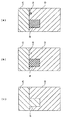
図1のブロック領域生成手段10は、図2(a)に示すように、画像Pを設定画素数毎に分割したブロック領域BRを生成する機能を有する。そして、ブロック領域生成手段10は生成したブロック領域BRをブロック領域識別手段30に送る。たとえば設定画素数が32画素×32画素である場合、画像Pから32×32画素からなるブロック領域BRが生成されることになる。
【0020】
オブジェクト抽出手段20は、図2(b)に示すように、画像Pを各オブジェクト毎に領域分割してオブジェクト領域ORを生成する機能を有する。そしてオブジェクト抽出手段20は生成した各オブジェクト領域ORをオブジェクト識別手段70に送る。
【0021】
ブロック領域識別手段30は生成された各ブロック領域BR毎に種類を識別する機能を有する。すなわち、ブロック領域識別手段30は、画像内のオブジェクトが「山」、「海」、「花」、「空」等の種類であることを特定するようになっている。ブロック領域識別手段30は識別した種類情報KIをオブジェクト識別手段70に送るようになっている。
【0022】
オブジェクト識別手段70は、送られたブロック領域BR毎の種類情報KIを用いて、分割されたオブジェクト領域OR毎に種類情報KIを付与して、オブジェクト領域ORの種類を識別可能にする機能を有する。具体的には、オブジェクト識別手段70は、オブジェクト領域OR内の各ブロック領域BRの種類情報KIを集計する。そして、オブジェクト識別手段70は、あるオブジェクト領域ORにおいて集計されたブロック領域BRの種類情報KIのうち、最も多いブロック領域BRの最大種類情報KImaxをオブジェクトの種類と識別する。なお、オブジェクト識別手段70は、複数のオブジェクト領域ORにまたがっているブロック領域BRは、カウントしないようになっている。すると、図2(c)に示すように、各オブジェクト領域ORに種類情報KIが付された状態になり、オブジェクト領域ORが種類情報KIによって識別可能となる。
【0023】
なお、図1のオブジェクト識別手段70において、オブジェクトの種類情報KIを多数決により決定するようにしているが、集計された種類情報KIのうち最も多い最大種類情報KImaxの割合(最大種類情報KImaxの数/オブジェクトを構成する全ブロック領域数)が種類情報しきい値KIrefより小さい場合、オブジェクト識別手段70がオブジェクトの種類情報KIとして「不明」を出力する機能を有していてもよい。あるいは、最大種類情報KImaxの割合と2番目に多い種類情報KIの割合との差が小さい場合、オブジェクト識別手段70がオブジェクトの種類情報KIとして「不明」を出力するようにしてもよい。これは、オブジェクトの種類情報KIを誤って識別するよりも、「不明」と判断された方がユーザーにとって好ましい場合があるためである。
【0024】
図3はオブジェクト抽出手段20の一例を示すブロック図であり、図3を参照してオブジェクト抽出手段20について説明する。なお、以下に示すオブジェクト抽出手段20は一例であり、たとえばエッジ検出により各オブジェクト領域ORを生成する手法等により行うようにしてもよい。
【0025】
オブジェクト抽出手段20は、画像Pを構成する各画素から複数の画素特徴量を抽出して、類似した画素特徴量毎に画素を分類する画像の特徴量分類手段100と、画素の分類毎に領域分割して複数のクラスタリング領域を生成する領域分割手段101と、生成されたクラスタリング領域を統合してオブジェクト領域を抽出する領域統合手段110とを有する。
【0026】
たとえば、類似した特徴を有する画素が図4(a)に示すように並んだ画像があると仮定する。すると、特徴量分類手段100において、各画素から複数の特徴量が抽出されて、各特徴量を要素とした複数の特徴ベクトルが生成される。その後、図4(b)に示すように、複数の特徴ベクトルが類似する特徴ベクトル毎に分類される(クラスタリング)。
【0027】
その後、領域分割手段101が、特徴量分類手段100によりクラスタリングされた結果を実際の画像に写像する。すると、図5(a)に示すように、類似した画素からなる複数のクラスタリング領域が形成される。このクラスタリング領域は、データベース111に記憶される。
【0028】
領域統合手段110は、領域分割手段101により分割されたクラスタリング領域を統合してオブジェクト領域ORを抽出する機能を有する。具体的には、領域統合手段110は最小クラスタ領域抽出手段112、統合領域判断手段113と接続されている。最小クラスタ領域抽出手段112は、データベース111内のクラスタリング領域のうち、最も画素数の少ない最小クラスタリング領域を抽出して領域統合手段110に送る。また、統合領域判断手段113は、抽出された最小クラスタリング領域と隣接する隣接クラスタリング領域をデーベース111内から抽出して領域統合手段110に送る。
【0029】
そして、最小クラスタリング領域が所定の微小画素しきい値以下の画素数(たとえば全画素数の1/100)の場合、領域統合手段110は、最小クラスタリング領域を境界画素数(周囲長)の最も多い隣接クラスタリング領域と統合させる。具体的には、図5(a)のクラスタリング領域Aが所定の微小画素しきい値以下の画素数を有する最小クラスタリング領域であるとする。クラスタリング領域Aは、クラスタリング領域C、Dと隣接しているため、クラスタリング領域C、Dが隣接クラスタリング領域となる。
【0030】
そこで、領域統合手段110において、最小クラスタリング領域Aとクラスタリング領域C、Dとが接している隣接画素数がそれぞれ算出される。図5(a)においては隣接クラスタリング領域Dとの境界画素数の方が隣接クラスタリング領域Cとの境界画素数よりも多い。このためクラスタリング領域Aは図7(b)のようにクラスタリング領域Dと統合する。
【0031】
また、最小クラスタリング領域が所定の小画素しきい値以下の画素数(たとえば全画素数の1/10)の場合、領域統合手段110は、最小クラスタリング領域を特徴空間での距離が近い隣接クラスタリング領域と統合させる。具体的には、図5(b)において、クラスタリング領域Dが所定の小画素しきい値以下の最小クラスタリング領域であるとする。すると、クラスタリング領域Bの隣接クラスタリング領域はクラスタリング領域C、Dである。そこで、たとえばテクスチャ情報を距離を基準とした場合、どちらのクラスタリング領域C、Dのテクスチャがクラスタリング領域Bのテクスチャに近いかが判断される。そして、図5(c)のように、クラスタリング領域Bが特徴空間での最も近い距離であるクラスタリング領域Dと統合される。
【0032】
領域統合手段110において、上述した作業がたとえば最小クラスタ領域抽出手段112から送られる最小クラスタリング領域が所定の小画素しきい値よりも大きい画素数になるまで行われる。すると、画像を各オブジェクト領域OR毎に領域分割することができる。
【0033】
次に、図1を参照してブロック領域識別手段30について説明する。ブロック領域識別手段30は、ブロック特徴量抽出手段40、写像手段50、種類出力手段60等を有する。特徴量抽出手段40は、ブロック領域BRから複数のブロック特徴量BCQを抽出する機能を有する。写像手段50は、たとえば自己組織化マップからなる2次元空間SOMを有し、複数のブロック特徴量BCQ(多次元特徴量)を二次元空間SOM上に写像するものである。種類出力手段60は、2次元空間SOM上の位置毎に種類情報KIを定義した種類頻度分布マップKDMを有する。そして、種類出力手段60は写像手段50により写像された2次元空間SOM上の座標情報CIから種類頻度分布マップKDMを用いてブロック領域BRの種類情報KIを出力するものである。以下にブロック領域識別手段30の各構成について具体的に説明していく。
【0034】
図6は特徴量抽出手段40の一例を示すブロック図であり、図6を参照して特徴量抽出手段40について説明する。ブロック特徴量抽出手段40は、色成分、明度成分および像的特徴成分からなる15個のブロック特徴量BCQを出力するものであって、Lab変換手段41、第1平均値算出手段42、第1ウェーブレット変換手段43、距離画像生成手段46、第2ウェーブレット変換手段47等を有する。
【0035】
Lab変換手段41は、RGB画像からなるブロック領域BRをLab画像に変換する機能を有する。平均値算出手段42は、Lab変換されたブロック領域BRのL成分、a成分およびb成分の平均値L−ave、a−ave、b−aveをそれぞれ算出する機能を有する。そして、算出された平均値L−ave、a−ave、b−aveが色成分を抽出したブロック特徴量BCQとなる。
【0036】
第1ウェーブレット変換手段43は、Lab変換されたブロック領域BRの明度成分をウェーブレット変換して明度成分の高周波成分L−LH、L−HL、L−HHを算出するものである。また第1ウェーブレット変換手段43に平均値算出手段44と最大値算出手段45とが接続されている。
【0037】
平均値算出手段44は、第1ウェーブレット変換手段43により算出された高周波成分L−LH、L−HL、L−HHの平均値L−LH−ave、L−HL−ave、L−HH−aveを算出するものである。そして、算出された平均値L−LH−ave、L−HL−ave、L−HH−aveが明度成分を抽出したブロック特徴量BCQとなる。
【0038】
また、最大値算出手段45は、第1ウェーブレット変換手段43により算出された高周波成分L−LH、L−HL、L−HHの頻度分布において大きい方から5%の値を算出するものである。この最大値L−LH−max、L−HL−max、L−HH−maxが明度成分を抽出したブロック特徴量BCQとなる。
【0039】
このように、L成分のブロック特徴量BCQとして平均値と最大値とを利用することにより、平均的に一定強度の高周波成分が分布してブロック領域BRと、一部に強い高周波成分があるブロック領域BRとを区別することができるようになり、ブロック領域BRの種類の識別を正確に行うことができるようになる。
【0040】
距離画像生成手段46は、Lab変換手段41によりLab変換されたブロック領域BRから距離画像Dを生成する機能を有する。ここで、距離画像Dは、一般的な距離画像とは異なり、図7に示すように、Lab変換した3変数のブロック領域BRと、ウェーブレット変換した際に生成したブロック領域BRの低周波成分からなるボケ画像とのユークリッド距離を画像化したものである。すなわち、Lab空間における3次元距離画像は、均等色空間における信号変動の様子を1枚の画像にしたものであり、人が知覚する変動を表現したものとして説明することができる。3次元空間での変動を扱うことにより、明度画像から得られない像構造的特徴を引き出すことができるため、種類情報KIの識別をより正確に行うことができる。
【0041】
つまり、各画素毎に抽出した画素特徴量に基づいて種類情報KIを識別した場合、像構造による種類の識別を行うことができないため、たとえば「空」と「海」のように像構造は異なるが明度や色が類似した種類情報KIの識別を精度よく行うことができない。一方、ブロック領域BR毎に距離画像Dを生成した像構造により種類情報KIの抽出を行うことにより、種類の識別をより正確に行うことができる。
【0042】
第2ウェーブレット変換手段47は生成された距離画像Dをウェーブレット変換して、その高周波成分D−LH、D−HL、D−HHを出力する機能を有する。第2ウェーブレット変換手段47に平均値算出手段48と最大値算出手段49とが接続されている。
【0043】
平均値算出手段48は、第2ウェーブレット変換手段47により算出された高周波成分D−LH、D−HL、D−HHの平均値D−LH−ave、D−HL−ave、D−HH−aveを算出するものである。そして、算出された平均値D−LH−ave、D−HL−ave、D−HH−aveが像的特徴成分を抽出したブロック特徴量BCQとなる。
【0044】
また、最大値算出手段49は、第1ウェーブレット変換手段43により算出された高周波成分D−LH、D−HL、D−HHの頻度分布において大きい方から5%の値を算出するものである。この最大値D−LH−max、D−HL−max、D−HH−maxが像的特徴成分を抽出したブロック特徴量BCQとなる。
【0045】
このように、D(距離)成分のブロック特徴量BCQとして平均値と最大値とを利用することにより、平均的に一定強度の高周波成分が分布してブロック領域BRと、一部に強い高周波成分があるブロック領域BRとを区別することができるようになり、ブロック領域BRの種類の判別を正確に行うことができるようになる。
【0046】
次に、図8は第1写像手段50および種類出力手段60の一例を示す模式図であり、図1と図8を参照して写像手段50および種類出力手段60について説明する。この第1写像手段50および種類出力手段60には自己組織化マップを用いた修正対向伝搬ネットワーク(参考文献:徳高、岸田、藤村「自己組織化マップの応用−多次元情報の2次元可視化」海文堂、1999)が用いられている。
【0047】
第1写像手段50は、複数のニューロンNをマトリックス状に配置した自己組織化マップからなる種類用2次元空間SOMkを有し、複数の特徴量(多次元特徴量)を種類用2次元空間SOMk上に写像する機能を有する。各ニューロンNはそれぞれブロック特徴量BCQと同一次元のベクトル座標を有する。本実施の形態においてはブロック特徴量BCQは15個のブロック特徴量BCQからなっているため、各ニューロンは15次元の結合荷重ベクトルからなっていることになる。
【0048】
そして、第1写像手段50は、1つのブロック領域BRから抽出された15個のブロック特徴量BCQを自己組織化マップSOMk上のニューロンNの中から、最も近似した(たとえば最もユークリッド距離等の近い)ニューロンNi(発火要素)を選択する。これにより、複数のブロック特徴量BCQからなる多次元空間から種類用2次元空間SOMk上に写像されたことになる。そして、第1写像手段50は選択したニューロンNiの第1座標情報CI1を種類出力手段60に送るようになっている。
【0049】
種類出力手段60は、種類用2次元空間SOMkと同一の座標系を有する複数の種類頻度分布マップKDMを有しており、第1写像手段50により写像された種類用2次元空間SOMk上の第1座標情報CI1から、種類頻度分布マップKDM上でその第1座標情報CI1の示す部位が示す種類情報KIを出力する機能を有する。この種類頻度分布マップKDMは、図9に示すように、各種類情報KI毎に種類用2次元空間上に様々な種類情報KIの分布が形成されており、各種類情報KI毎にそれぞれ種類頻度分布マップKDMが用意されている。たとえば、種類情報KIが「空」の分布は、図9(a)のように種類頻度分布マップKDMの右側面側および左上部の領域に形成されている。同様に、図9(b)の種類情報KIが「建物」の種類頻度分布マップKDM、図9(c)の種類情報がKIが「木」の種類頻度分布マップKDMおよび図9(d)の種類情報KIが「海」の種類頻度分布マップKDMをそれぞれ示している。
【0050】
なお、各種類情報KI毎に種類頻度分布マップKDMが用意されている場合について例示しているが、1枚の種類頻度分布マップKDMに複数の種類情報KIの分布が形成されていてもよい。
【0051】
ここで、上述した種類情報KIを識別する際(認識モード)に使用される自己組織化マップSOMkおよび種類頻度分布マップKDMは、予め学習されたものが使用される。すなわち、種類用2次元空間SOMkおよび種類頻度分布マップKDMは学習機能を有しており、予め種類情報KIが判っているブロック領域BRから抽出されたブロック特徴量BCQからなる学習入力データを用いて各ニューロンNおよび種類頻度分布マップKDMが学習される。
【0052】
まず自己組織化マップSOMkの学習について説明する。自己組織化マップSOMkのニューロンは、初期状態においてランダムな結合荷重ベクトルを有している。そして、予め種類情報KIのわかっている学習用入力データが第1写像手段50に入力される。すると、第1写像手段50により学習用入力データと最も近似したニューロンNi(発火要素)が選択される。同時に、選択されたニューロンNi(発火要素)を取り囲むたとえば3×3個のニューロンが選択される。そして、ニューロンNi(発火要素)およびその近傍にあるニューロンNの結合荷重ベクトルが学習用入力データに近づく方向に更新されて、自己組織化マップSOMkのニューロンNが学習される。
【0053】
次に、種類頻度分布マップKDMの学習について説明する。種類頻度分布マップKDMにおいてすべての座標の初期値は0になっている。上述したように、自己組織化マップSOMkに学習用入力データが写像された際に、第1写像手段50は学習用入力データが写像された自己組織化マップSOMk上の第1座標情報CI1を種類出力手段60に送る。すると、種類出力手段60は、種類頻度分布マップKDM内の第1座標情報CI1に当たる部位およびそれを取り囲む領域(たとえば3×3個)に正の整数値(たとえば「1」)が加算される。
【0054】
そして、学習入力データが入力されて行くにつれて、種類頻度分布マップKDM上の特定の領域ついて学習入力データの入力により数値が加算されて大きくなっていく。つまり、同じ種類のブロック領域BRであれば、ブロック特徴量BCQが類似していることになる。ブロック特徴量BCQが類似していれば、自己組織化マップSOMk上の近くの座標に写像されることが多くなるため、種類頻度分布マップKDMにおいても特定の座標の数値が大きくなっていく。
【0055】
この作業が複数の学習入力データを用いて行われるとともに、この学習入力データが複数回繰り返し自己組織化マップSOMkに入力される。ここで、複数の学習入力データの入力が繰り返されるに連れて、座標上の数値が更新される領域が狭くなっていき、最後には選択された座標上の数値のみが更新される。
【0056】
最後に、種類頻度分布マップKDMの各座標にある数値を全入力学習データ数×学習回数で割ると、各座標に0.0から1.0までの確率が入力された種類頻度分布マップKDMが生成される。この確率が大きければ大きいほど、その種類である確率が大きくなることを意味する。図9の種類頻度分布マップKDMにおいては、白の範囲が0.8〜1.0の信頼度(確率)、グレーの範囲が0.2〜0.8の信頼度(確率)、黒の範囲が0.0〜0.2の信頼度(確率)を示している。このように種類頻度分布マップKDMがたとえば「空」、「建物」、「木」、「海」等の種類情報KI毎にそれぞれ形成されていく。
【0057】
そして、実際のブロック領域BRについて種類の識別をする際(認識モード)では、種類出力手段60は、複数の種類頻度分布マップKDMからそれぞれ第1座標情報CI1の部位が有する信頼度を抽出する。具体的には、第1写像手段50から第1座標情報CI1が送られてきた場合、たとえば「空」、「建物」、「木」、「海」等のそれぞれの種類頻度分布マップKDM上の第1座標情報CI1に該当する部位の信頼度を抽出する。そして、種類出力手段60は、各種類頻度分布マップKDMから得られた確率をベクトル成分とする種類ベクトルを生成する。この場合、空の信頼度、建物の信頼度、木の信頼度および海の信頼度をベクトル成分とする種類ベクトルが生成される。その後、種類出力手段60は最も大きい確率を有する種類情報KIをブロック領域BRの種類情報であると識別して、種類情報KIをオブジェクト識別手段70に送る。
【0058】
なお、種類出力手段60において、上述した種類ベクトルを構成するベクトル成分が、所定のベクトル成分しきい値より小さい場合、ブロック領域BRの種類情報KIの識別の確信度が低いと判断して、「不明」とした種類情報KIをオブジェクト識別手段70に送るようにしてもよい。もしくは最も大きいベクトル成分と2番目に大きいベクトル成分との差が小さい場合にも同様に、ブロック領域BRの種類情報KIの識別の確信度が低いと判断して、種類情報KIを「不明」としてオブジェクト識別手段70に送るようにしてもよい。これにより、種類情報KIの識別について信頼性の低いブロック領域BRについてはオブジェクト領域ORの種類情報KIの識別に与える影響を少なくすることができるため、オブジェクト領域ORの識別の精度を向上させることができる。
【0059】
さらに、第1写像手段50が送られた複数のブロック特徴量BCQを自己組織化マップSOMに写像する際に、最も近似したニューロンNi(発火要素)と複数のブロック特徴量BCQとの距離(たとえばユークリッド距離等)が所定の距離しきい値より大きい場合、第1写像手段50は種類出力手段60に対してマッチング処理を行わない旨の情報を送るようにしてもよい。その場合、種類出力手段60においても、種類情報KIを「不明」とする種類情報KIをオブジェクト識別手段70に送るようにしてもよい。この場合であっても、種類情報KIの識別について信頼性の低いブロック領域BRについてはオブジェクト領域ORの種類情報KIの識別に与える影響を少なくすることができるため、オブジェクト領域ORの識別の精度を向上させることができる。
【0060】
図10はオブジェクト識別方法の一例を示すフローチャート図であり、図1から図10を参照してオブジェクト識別方法について説明する。まず、オブジェクト抽出手段20により入力された画像をオブジェクト毎に領域分割したオブジェクト領域ORが生成される。一方では、ブロック領域生成手段10により入力された画像を設定画素数(たとえば32×32画素)からなるオブジェクト領域ORより小さい複数のブロック領域BRが生成される。(ステップST1)。
【0061】
次に、ブロック特徴量抽出手段40により、ブロック領域BRから15個の特徴量BCQが抽出される(ステップST2)。その後、抽出した特徴量BCQが第1写像手段50により自己組織化マップSOMkに写像されて、自己組織化マップSOMkの位置CIが種類出力手段60に送られる(ステップST3)。種類出力手段60において、種類頻度分布マップKDMから位置CIの種類情報KIを抽出して、オブジェクト識別手段70に送る(ステップST4)。この作業がすべてのブロック領域BRについて行われる(ステップST5)。
【0062】
その後、オブジェクト識別手段70において、各オブジェクト領域OR毎に付与された種類情報KIを集計する(ステップST6)。そして、最も多い種類情報KIがそのオブジェクト領域ORの種類情報として出力される(ステップST7)。
【0063】
図11はシーン識別手段80の一例を示すブロック図であり、図11を参照してシーン識別手段80について説明する。シーン識別手段80は、オブジェクト識別手段70により識別された各オブジェクト毎の種類を用いて画像Pのシーンを識別するものであって、識別ベクトル生成手段81、第2写像手段82、識別シーン出力手段83等を有している。
【0064】
識別ベクトル生成手段81は、オブジェクト識別手段70により識別されたオブジェクト領域ORの種類KIを識別ベクトルAPに変換する機能を有する。具体的には、図12(a)に示すように、識別ベクトル生成手段81は、オブジェクトの種類毎に識別番号を付した識別テーブル81aを有している。識別ベクトル生成手段81は1つの画像に含まれるすべてのオブジェクト領域ORに付された種類を識別テーブル81aを用いて識別番号に変換する。よって、画像が図12(b)に示すような識別番号を画素値とする画像に変換されることになる。そして、識別ベクトル生成手段81は、識別番号を画素値とした画像の画像サイズを規格化した識別ベクトルAPを生成する。
【0065】
図11の第2写像手段82および識別シーン出力手段83は、上述した第1写像手段50および種類出力手段60と同一の構成を有している。具体的には、第2写像手段82は、自己組織化マップからなるシーン用2次元空間SOMsを有しており、識別シーン出力手段83は、シーン頻度分布マップSDMを有している。このシーン用2次元空間SOMsおよびシーン頻度分布マップSDMは、識別ベクトルAPを学習入力データとして用いて、上述した種類用2次元空間SOMkおよび種類頻度分布マップKDMと同様の手法により、学習されたものである。
【0066】
したがって、識別シーン出力手段83は、たとえば「ポートレート」、「集合写真」もしくは「サッカーのシーン」、「ゴルフのシーン」等の各シーン毎にそれぞれシーン頻度分布マップSDMを有している状態になっている。
【0067】
ここで、第2写像手段82は、識別ベクトルAPをシーン用2次元空間SOMs上に写像して識別ベクトルに最も近似したニューロンを選択してその第2座標情報CI2を取得する。そして第2写像手段82は取得した第2座標情報CI2を識別シーン出力手段83に送る。識別シーン出力手段83は、送られた第2座標情報CI2を用いてシーン頻度分布マップSDMからシーン情報SIを抽出して出力する。
【0068】
また、識別シーン出力手段83において、上述した種類出力手段60と同様に、複数のシーン頻度分布マップSDMから得られる各シーンの数値のうち最も大きいものが所定のしきい値(たとえば0.5)より小さい場合、シーンの識別の確信度が低いと判断して、シーン情報を「不明」とするようにしてもよい。
【0069】
図13は本発明のシーン識別方法の好ましい実施の形態を示すフローチャート図であり、図11から図13を参照してオブジェクト識別方法について説明する。まず、オブジェクト抽出手段20において、入力された画像Pがオブジェクト領域OR毎に領域分割される(ステップST10)。その後、オブジェクト識別手段70において、上述したステップST1〜ステップST7の手法により、抽出されたオブジェクト領域OR毎に種類情報KIが付される(ステップST11)。そして、各オブジェクト領域ORに対して付された複数の種類情報KIがシーン識別手段80に入力される。
【0070】
すると、識別ベクトル生成手段81により、入力された複数の種類情報KIを用いて識別ベクトルAPが生成される(ステップST12)。次に、識別ベクトルが第2写像手段82により自己組織化マップSOMkに入力されて、自己組織化マップSOMk上の座標情報が識別シーン出力手段83に出力される。そして、識別シーン出力手段83において、出力された座標情報に当たるシーン頻度分布マップSDM上のシーン情報SIが抽出されて出力される(ステップST13)。
【0071】
上記実施の形態によれば、複数のオブジェクトを有する画像Pからオブジェクト領域ORを抽出し、複数のオブジェクト領域OR毎に種類を識別し、各オブジェクト領域OR毎の種類を用いて画像のシーンを識別することにより、画像Pのシーンを自動的に識別することができるようになり、画像の分類および検索を容易に行うことができる。すなわち、画像Pの物理的特徴に基づいて分類および検索を行う場合、たとえば肌と砂のように物理的特徴が類似していても意味が異なるものについては正確に分類・検索することができない。一方、画像Pのシーンを自動的に識別することができれば、精度よく画像Pの分類・検索を行うことができる。また、オブジェクトの種類の識別および画像Pのシーンの識別にいわゆる修正対向伝搬ネットワークを用いることにより、シーンの識別を精度よく効率的に行うことができる。
【0072】
なお、本発明の実施の形態は上記実施の形態に限定されない。たとえば、上記実施の形態において、シーン識別手段80は、1つの画像のシーンを識別する場合について言及しているが、複数の画像のシーンを識別して、識別した複数の画像Pからなる画像群PGのシーンを識別するようにしてもよい。具体的には、図14に示すように、シーン識別手段80が、識別した複数の画像からなる画像群のシーンを記憶する記憶手段84、画像群のシーンを識別するための画像群識別手段85を有している。この画像群識別手段85は、上述したシーン識別手段80と同一の構成(修正対向伝搬ネットワーク)を有するものである。そして、画像群識別手段85は、予め画像群に占める各シーンの頻度分布(比率)をベクトル成分とするシーンベクトルから「運動会」や「旅行」等のイベント情報を識別できるように学習されている。
【0073】
すると、まず画像群識別手段85おいて、記憶手段84に記憶された画像群を構成する各画像のシーンを用いて、画像群に占める各シーンの頻度分布(比率)、たとえば風景シーンの比率、室内シーンの比率、ポートレートシーンの比率等が算出されてシーンベクトルが生成される。そして、生成されたシーンベクトルが修正対向伝搬ネットワークに入力されると、画像群のたとえば「運動会」や「旅行」等の画像群のシーン(イベント記述)毎にそれぞれ信頼度が出力される。出力された複数の信頼度のうち、最も大きい信頼度を画像群に対するイベント記述として識別する。これにより、画像群についてもシーンを自動的に識別できるようになるため、画像群の検索・分類を効率的に行うことができる。
【0074】
なお、シーンベクトルのベクトル成分が、上述した画像群に示す各シーンの比率である場合に限定されず、たとえば画像群に含まれるオブジェクト領域ORの種類の比率を用いてもよい。また、画像群識別手段85が画像群のイベント記述を画像群のシーンとして識別する場合について例示しているが、たとえば画像群が「風景シーン」「室内シーン」等のシーンを識別するものであってもよい。
【図面の簡単な説明】
【図1】本発明のシーン識別装置の第1の実施の形態を示すブロック図
【図2】本発明のシーン識別装置において、画像に含まれるオブジェクト毎に種類が識別される様子を示す図
【図3】本発明のシーン識別装置におけるオブジェクト抽出手段の一例を示すブロック図
【図4】図2のオブジェクト抽出手段により画像が領域分割される様子を示す図
【図5】図2のオブジェクト抽出手段によりクラスタリング領域が統合されてオブジェクト領域が形成される様子を示す図
【図6】本発明のシーン識別装置におけるブロック特徴量抽出手段の一例を示すブロック図
【図7】本発明のシーン識別装置における距離画像生成手段における距離画像の生成の様子を示すブロック図
【図8】本発明のシーン識別装置における写像手段および種類出力手段の一例を示すブロック図
【図9】本発明のシーン識別装置における種類頻度分布マップの一例を示すブロック図
【図10】オブジェクト識別方法の一例を示すフローチャート図
【図11】本発明のシーン識別装置におけるシーン識別手段の一例を示すブロック図
【図12】図10の識別ベクトル生成手段における各種類毎の識別ベクトルを示す図
【図13】本発明のシーン識別方法の好ましい実施の形態を示すフローチャート図
【図14】本発明のシーン識別装置におけるシーン識別手段の別の一例を示すブロック図
【符号の説明】
1 シーン識別装置
20 オブジェクト抽出手段
70 オブジェクト識別手段
80 シーン識別手段
AP 識別ベクトル
CI 位置
CP 分類パラメータ
KDM 各種類頻度分布マップ
KI 各種類情報
OR オブジェクト領域
P 画像
PG 画像群
SDM シーン頻度分布マップ
SI シーン情報[0001]
BACKGROUND OF THE INVENTION
The present invention relates to a scene identification method, apparatus, and program for automatically identifying an image scene.
[0002]
[Prior art]
If the image information captured by a digital camera or the like can identify what image is captured in the image information, for example, classification, search, or image processing may be performed for each type of object included in the image. it can.
[0003]
For example, when classifying and searching for images, an image search system has been proposed in which similarity is determined using physical feature amounts included in images. For example, there is a technique in which a local region of an input image is extracted, and the local region is collated with a reference image while changing its position and size to classify and search images. In addition, in the above method, there is a method for efficiently classifying and searching images by detecting the position of an object by using a color histogram of a local region and comparing the histogram with a color histogram of a reference image (electronic information communication). Journal of Society, vol.j81-DII, no.9, pp.2035-2042, 1998). However, in any of the above-described methods, since the similarity is identified by the physical feature amount of the image, it may be determined that the similarity is not similar in type due to the similarity of the physical amount. There is a problem that the accuracy of the search is poor.
[0004]
[Problems to be solved by the invention]
As described above, when classifying and searching for an image based on information directly obtained from the image, appropriate information cannot be provided to the user. As one method for solving this, it may be possible to classify, search, or perform image processing after identifying a scene. Then, in image classification / retrieval, classification / retrieval can be performed according to the identified scene. Therefore, image classification / retrieval can be performed easily and accurately. Even when image processing is performed, image processing can be performed using image processing conditions suitable for the scene.
[0005]
At this time, for example, it is conceivable that the user extracts an object region while looking at the screen and inputs scene information for each image. However, there is a problem that it takes time to input an image scene by the user.
[0006]
SUMMARY OF THE INVENTION An object of the present invention is to provide a scene identification method, apparatus, and program that can automatically identify a scene.
[0007]
[Means for Solving the Problems]
The scene identification method of the present invention is a scene identification method for identifying a scene of an image having a plurality of objects, the step of extracting a plurality of object regions from the image, and identifying the type of object for each of the plurality of extracted object regions. And a step of identifying an image scene using a type of each identified object.
[0008]
The scene identification device according to the present invention is a scene identification device for identifying a scene of an image having a plurality of objects, an object extraction means for extracting a plurality of object regions from the image, and an object type for each of the plurality of extracted object regions. And object identifying means for identifying the scene, and scene identifying means for identifying the scene of the image using the type of each identified object.
[0009]
The scene identification program of the present invention uses a procedure for extracting an object region from an image having a plurality of objects, a procedure for identifying the type of object for each of the plurality of extracted object regions, and a type for each identified object. And a procedure for identifying a scene of an image by a computer.
[0010]
Here, “object” means a subject included in an image such as a person, sky, sea, tree, building, etc., and “object region” means a region occupied by the subject in the image.
[0011]
“Identify the object type” means that the object in the image is of a type such as “mountain”, “sea”, “flower”, “sky”, etc. It also includes specifying “unknown” when not sure.
[0012]
The “scene identifying means” has a function of not only identifying a scene of one image but also identifying a scene for an image and identifying a scene of an image group composed of the plurality of images from the identified plurality of image scenes. You may have.
[0013]
The “scene identifying means” may be any means for identifying the scene of the image, and mapping means for mapping the types of the identified object areas to the scene two-dimensional space, and the scene two-dimensional space. An identification scene information output means having a scene frequency distribution map defining a scene for each of the upper coordinates, and identifying a scene whose coordinates in the mapped scene two-dimensional space are indicated on the scene frequency distribution map as an image scene; You may have.
[0014]
The “scene two-dimensional space” may be a self-organizing map in which a plurality of neurons having a learning function are arranged in a matrix.
[0015]
【The invention's effect】
According to the scene identification method, apparatus, and program of the present invention, an object region is extracted from an image having a plurality of objects, an object type is identified for each of the plurality of object regions, and an image scene is identified using the type for each object. Thus, the scene of the image can be automatically specified, and the classification and retrieval of the image can be easily performed.
[0016]
In addition, the scene identification unit has a function of identifying a scene for an image and identifying a scene of an image group including the plurality of images from the identified plurality of image scenes. For example, a scene about an image group such as a moving image or a continuous photograph composed of a plurality of image frames can be automatically identified, and the image group can be easily classified and searched.
[0017]
Further, the scene identifying means has mapping means for mapping types for each of the plurality of identified object areas to a two-dimensional space, and a scene frequency distribution map in which a scene is defined for each coordinate in the scene identifying two-dimensional space. The identification scene information output means for identifying the scene whose mapped coordinates in the two-dimensional space are indicated on the scene frequency distribution map as the image scene can be used to accurately and efficiently identify the scene. .
[0018]
DETAILED DESCRIPTION OF THE INVENTION
FIG. 1 is a block diagram showing a first embodiment of a scene identification apparatus according to the present invention. The scene identification apparatus 1 will be described with reference to FIG. The scene identification device 1 automatically identifies the scene of the image P from the object configuration of the entire image. For example, the scene identification device 1 not only roughly identifies scenes such as “landscape scene” and “indoor scene” as image P, but also “portrait”, “group photo” or “soccer scene”, “golf scene” A scene such as a “scene” is automatically identified. The scene identification apparatus 1 includes a block
[0019]
As shown in FIG. 2A, the block
[0020]
As shown in FIG. 2B, the object extraction means 20 has a function of generating an object area OR by dividing an image P into areas for each object. Then, the
[0021]
The block area identifying means 30 has a function of identifying the type for each generated block area BR. In other words, the block area identifying means 30 identifies that the object in the image is of a type such as “mountain”, “sea”, “flower”, “sky”. The block
[0022]
The object identification means 70 has a function of identifying the type of the object area OR by giving the type information KI to each divided object area OR using the type information KI for each block area BR sent. . Specifically, the object identification means 70 totals the type information KI of each block area BR in the object area OR. Then, the
[0023]
1, the object type information KI is determined by majority decision. However, the ratio of the largest type information KImax that is the largest of the total type information KI (the number of the maximum type information KImax). / The total number of block areas constituting the object) may be smaller than the type information threshold value KIref, the
[0024]
FIG. 3 is a block diagram showing an example of the
[0025]
The object extraction means 20 extracts a plurality of pixel feature values from each pixel constituting the image P, classifies the pixels for each similar pixel feature value, and an area for each pixel classification. A
[0026]
For example, assume that there is an image in which pixels having similar characteristics are arranged as shown in FIG. Then, the feature
[0027]
Thereafter, the
[0028]
The
[0029]
When the minimum clustering area has a number of pixels equal to or smaller than a predetermined minute pixel threshold (for example, 1/100 of the total number of pixels), the
[0030]
Therefore, the
[0031]
When the minimum clustering area has a number of pixels equal to or smaller than a predetermined small pixel threshold (for example, 1/10 of the total number of pixels), the
[0032]
In the
[0033]
Next, the block area identifying means 30 will be described with reference to FIG. The block
[0034]
FIG. 6 is a block diagram illustrating an example of the feature
[0035]
The Lab conversion means 41 has a function of converting a block area BR formed of RGB images into a Lab image. The average value calculating means 42 has a function of calculating average values L-ave, a-ave, and b-ave of the L component, a component, and b component of the block region BR subjected to Lab conversion. The calculated average values L-ave, a-ave, and b-ave are the block feature values BCQ from which the color components are extracted.
[0036]
The first
[0037]
The average value calculating means 44 is the average values L-LH-ave, L-HL-ave, L-HH-ave of the high frequency components L-LH, L-HL, L-HH calculated by the first wavelet transform means 43. Is calculated. The calculated average values L-LH-ave, L-HL-ave, and L-HH-ave are the block feature values BCQ from which the brightness components are extracted.
[0038]
The maximum value calculating means 45 calculates a value of 5% from the largest in the frequency distribution of the high frequency components L-LH, L-HL, and L-HH calculated by the first wavelet transform means 43. The maximum values L-LH-max, L-HL-max, and L-HH-max become the block feature value BCQ from which the brightness component is extracted.
[0039]
In this way, by using the average value and the maximum value as the block feature value BCQ of the L component, a high frequency component having a constant intensity is distributed on average, and the block region BR and a block having a strong high frequency component in part. The region BR can be distinguished from the region BR, and the type of the block region BR can be accurately identified.
[0040]
The distance
[0041]
That is, when the type information KI is identified based on the pixel feature amount extracted for each pixel, the type cannot be identified by the image structure, and thus the image structure is different, for example, “sky” and “sea”. However, it is impossible to accurately identify the type information KI having similar brightness and color. On the other hand, by identifying the type information KI using the image structure in which the distance image D is generated for each block region BR, the type can be identified more accurately.
[0042]
The second
[0043]
The average value calculating means 48 is the average values D-LH-ave, D-HL-ave, D-HH-ave of the high frequency components D-LH, D-HL, D-HH calculated by the second wavelet transform means 47. Is calculated. The calculated average values D-LH-ave, D-HL-ave, and D-HH-ave are the block feature values BCQ from which the image feature components are extracted.
[0044]
The maximum value calculation means 49 calculates a value of 5% from the largest in the frequency distribution of the high frequency components D-LH, D-HL, and D-HH calculated by the first wavelet transform means 43. The maximum values D-LH-max, D-HL-max, and D-HH-max become block feature values BCQ from which image feature components are extracted.
[0045]
In this way, by using the average value and the maximum value as the block feature value BCQ of the D (distance) component, the high-frequency component having a constant intensity is distributed on the average, and the block region BR and the high-frequency component strong in part. This makes it possible to distinguish a certain block area BR from a certain block area BR, and to accurately determine the type of the block area BR.
[0046]
Next, FIG. 8 is a schematic diagram showing an example of the
[0047]
The first mapping means 50 has a type two-dimensional space SOMk composed of a self-organizing map in which a plurality of neurons N are arranged in a matrix, and a plurality of feature quantities (multidimensional feature quantities) are used for the type two-dimensional space SOMk. Has the function of mapping up. Each neuron N has a vector coordinate in the same dimension as the block feature BCQ. In the present embodiment, since the block feature value BCQ is composed of 15 block feature values BCQ, each neuron is composed of a 15-dimensional connection weight vector.
[0048]
Then, the first mapping means 50 most closely approximates the 15 block feature values BCQ extracted from one block region BR from among the neurons N on the self-organizing map SOMk (for example, the closest Euclidean distance or the like). ) Select a neuron Ni (firing element). As a result, the multi-dimensional space composed of a plurality of block feature values BCQ is mapped onto the type two-dimensional space SOMk. Then, the first mapping means 50 sends the first coordinate information CI1 of the selected neuron Ni to the type output means 60.
[0049]
The
[0050]
In addition, although the case where the type frequency distribution map KDM is prepared for each type information KI is illustrated, the distribution of a plurality of type information KI may be formed in one type frequency distribution map KDM.
[0051]
Here, the self-organized map SOMk and the type frequency distribution map KDM used when identifying the type information KI (recognition mode) described above are used in advance. That is, the type two-dimensional space SOMk and the type frequency distribution map KDM have a learning function, and use learning input data composed of block feature values BCQ extracted from the block region BR whose type information KI is known in advance. Each neuron N and the type frequency distribution map KDM are learned.
[0052]
First, learning of the self-organizing map SOMk will be described. The neurons of the self-organizing map SOMk have random connection weight vectors in the initial state. Then, learning input data whose type information KI is known in advance is input to the first mapping means 50. Then, the first mapping means 50 selects the neuron Ni (firing element) that most closely approximates the learning input data. At the same time, for example 3 × 3 neurons surrounding the selected neuron Ni (firing element) are selected. Then, the connection weight vector of the neuron Ni (firing element) and the neuron N in the vicinity thereof is updated in a direction approaching the learning input data, and the neuron N of the self-organizing map SOMk is learned.
[0053]
Next, learning of the type frequency distribution map KDM will be described. In the type frequency distribution map KDM, initial values of all coordinates are zero. As described above, when the learning input data is mapped to the self-organizing map SOMk, the first mapping means 50 uses the first coordinate information CI1 on the self-organizing map SOMk on which the learning input data is mapped. Send to output means 60. Then, the type output means 60 adds a positive integer value (for example, “1”) to the portion corresponding to the first coordinate information CI1 in the type frequency distribution map KDM and the region (for example, 3 × 3) surrounding it.
[0054]
Then, as learning input data is input, numerical values are added to the specific area on the type frequency distribution map KDM to increase as learning input data is input. That is, if the same type of block region BR, the block feature amount BCQ is similar. If the block feature values BCQ are similar, they are often mapped to nearby coordinates on the self-organizing map SOMk. Therefore, the numerical values of specific coordinates also increase in the type frequency distribution map KDM.
[0055]
This operation is performed using a plurality of learning input data, and the learning input data is repeatedly input a plurality of times into the self-organizing map SOMk. Here, as the input of a plurality of learning input data is repeated, the area in which the numerical values on the coordinates are updated becomes narrower, and finally only the numerical values on the selected coordinates are updated.
[0056]
Finally, when the numerical value at each coordinate of the type frequency distribution map KDM is divided by the total number of input learning data times the number of learnings, the type frequency distribution map KDM in which a probability of 0.0 to 1.0 is input to each coordinate is obtained. Generated. This means that the greater the probability, the greater the probability of that type. In the type frequency distribution map KDM of FIG. 9, the reliability (probability) in the white range is 0.8 to 1.0, the reliability (probability) in the gray range is 0.2 to 0.8, and the black range. Indicates a reliability (probability) of 0.0 to 0.2. In this way, the type frequency distribution map KDM is formed for each type information KI such as “sky”, “building”, “tree”, “sea”, and the like.
[0057]
When identifying the type of the actual block region BR (recognition mode), the
[0058]
In the type output means 60, if the vector component constituting the above-described type vector is smaller than the predetermined vector component threshold, it is determined that the certainty of identifying the type information KI of the block region BR is low, and “ You may make it send the kind information KI made into "unknown" to the object identification means 70. FIG. Alternatively, when the difference between the largest vector component and the second largest vector component is small, similarly, it is determined that the certainty of identification of the type information KI of the block region BR is low, and the type information KI is set to “unknown”. You may make it send to the object identification means 70. FIG. As a result, the block area BR having low reliability for identifying the type information KI can reduce the influence on the identification of the type information KI of the object area OR, so that the accuracy of identifying the object area OR can be improved. it can.
[0059]
Further, when mapping the plurality of block feature values BCQ sent by the first mapping means 50 to the self-organizing map SOM, the distance between the most approximate neuron Ni (firing element) and the plurality of block feature values BCQ (for example, If the Euclidean distance or the like is larger than a predetermined distance threshold, the
[0060]
FIG. 10 is a flowchart showing an example of the object identification method. The object identification method will be described with reference to FIGS. First, an object area OR is generated by dividing an image input by the
[0061]
Next, 15 feature values BCQ are extracted from the block region BR by the block feature value extracting means 40 (step ST2). Thereafter, the extracted feature value BCQ is mapped to the self-organizing map SOMk by the first mapping means 50, and the position CI of the self-organizing map SOMk is sent to the type output means 60 (step ST3). The type output means 60 extracts the type information KI of the position CI from the type frequency distribution map KDM and sends it to the object identification means 70 (step ST4). This operation is performed for all the block areas BR (step ST5).
[0062]
Thereafter, in the object identification means 70, the type information KI given for each object area OR is totaled (step ST6). Then, the most type information KI is output as the type information of the object area OR (step ST7).
[0063]
FIG. 11 is a block diagram showing an example of the
[0064]
The identification vector generation means 81 has a function of converting the type KI of the object area OR identified by the object identification means 70 into an identification vector AP. Specifically, as shown in FIG. 12A, the identification vector generation means 81 has an identification table 81a in which an identification number is assigned for each object type. The identification vector generation means 81 converts the types assigned to all object regions OR included in one image into identification numbers using the identification table 81a. Therefore, the image is converted into an image having an identification number as shown in FIG. 12B as a pixel value. Then, the identification vector generation means 81 generates an identification vector AP in which the image size of the image with the identification number as the pixel value is standardized.
[0065]
The
[0066]
Accordingly, the identification scene output means 83 has a scene frequency distribution map SDM for each scene such as “portrait”, “group photo” or “soccer scene”, “golf scene”, etc. It has become.
[0067]
Here, the second mapping means 82 maps the identification vector AP onto the scene two-dimensional space SOMs, selects the neuron most approximate to the identification vector, and acquires the second coordinate information CI2. Then, the second mapping means 82 sends the acquired second coordinate information CI2 to the identification scene output means 83. The identification scene output means 83 extracts and outputs the scene information SI from the scene frequency distribution map SDM using the sent second coordinate information CI2.
[0068]
In the identification
[0069]
FIG. 13 is a flowchart showing a preferred embodiment of the scene identification method of the present invention. The object identification method will be described with reference to FIGS. First, in the object extraction means 20, the input image P is divided into regions for each object region OR (step ST10). Thereafter, in the object identification means 70, the type information KI is attached to each extracted object region OR by the method of step ST1 to step ST7 described above (step ST11). A plurality of types of information KI attached to each object area OR is input to the
[0070]
Then, an identification vector AP is generated by the identification vector generation means 81 using a plurality of input type information KI (step ST12). Next, the identification vector is input to the self-organizing map SOMk by the
[0071]
According to the above embodiment, the object area OR is extracted from the image P having a plurality of objects, the type is identified for each of the plurality of object areas OR, and the scene of the image is identified using the type for each object area OR. By doing so, the scene of the image P can be automatically identified, and the classification and retrieval of the image can be easily performed. That is, when performing classification and search based on the physical features of the image P, even if the physical features are similar, such as skin and sand, they cannot be classified and searched accurately even if they have different meanings. On the other hand, if the scene of the image P can be automatically identified, the image P can be classified and searched with high accuracy. Further, by using a so-called modified counter-propagation network for identifying the object type and identifying the scene of the image P, the scene can be identified with high accuracy and efficiency.
[0072]
The embodiment of the present invention is not limited to the above embodiment. For example, in the above embodiment, the
[0073]
Then, first, in the image
[0074]
Note that the present invention is not limited to the case where the vector component of the scene vector is the ratio of each scene shown in the above-described image group. For example, the ratio of the types of object regions OR included in the image group may be used. Further, although the case where the image
[Brief description of the drawings]
FIG. 1 is a block diagram showing a first embodiment of a scene identification device of the present invention.
FIG. 2 is a diagram illustrating a state in which a type is identified for each object included in an image in the scene identification device of the present invention.
FIG. 3 is a block diagram showing an example of object extraction means in the scene identification device of the present invention.
4 is a diagram illustrating a state in which an image is divided into regions by the object extraction unit in FIG. 2;
5 is a diagram showing a state in which clustering regions are integrated by the object extraction unit in FIG. 2 to form an object region.
FIG. 6 is a block diagram showing an example of block feature amount extraction means in the scene identification apparatus of the present invention.
FIG. 7 is a block diagram showing how a distance image is generated by a distance image generating means in the scene identification apparatus of the present invention.
FIG. 8 is a block diagram showing an example of mapping means and type output means in the scene identification device of the present invention.
FIG. 9 is a block diagram showing an example of a type frequency distribution map in the scene identification device of the present invention.
FIG. 10 is a flowchart showing an example of an object identification method.
FIG. 11 is a block diagram showing an example of scene identification means in the scene identification device of the present invention.
12 is a diagram showing an identification vector for each type in the identification vector generating means of FIG.
FIG. 13 is a flowchart showing a preferred embodiment of the scene identification method of the present invention.
FIG. 14 is a block diagram showing another example of scene identification means in the scene identification device of the present invention.
[Explanation of symbols]
1 Scene identification device
20 Object extraction means
70 Object identification means
80 Scene identification means
AP identification vector
CI position
CP classification parameters
KDM each type frequency distribution map
KI each kind information
OR object area
P image
PG image group
SDM scene frequency distribution map
SI scene information
Claims (27)
前記画像を設定画素ごとに分割したブロック領域を生成するブロック領域生成ステップと、
生成された前記各ブロック領域毎に該ブロック領域の種類を識別するブロック領域識別ステップと、
前記画像を前記複数のオブジェクト毎に領域分割してオブジェクト領域を生成するオブジェクト抽出ステップと、
前記オブジェクト領域内に含まれる前記複数のブロック領域の種類情報を用いて前記オブジェクト領域毎に種類情報を付与し前記各オブジェクト領域の種類を識別する画像内オブジェクト識別ステップと、
前記オブジェクト領域の種類毎に識別番号が付された識別テーブルを参照することにより、前記オブジェクト領域に付された前記種類情報を前記識別番号に変換し、該画像に含まれる前記複数のオブジェクト領域の前記識別番号を用いて識別ベクトルを生成する識別ベクトル生成ステップと、
前記識別ベクトルを入力して前記画像のシーンを識別して出力するシーン識別ステップと
を有し、
前記シーン識別ステップが、
前記識別ベクトルを入力としてシーン用2次元空間を用いて座標情報を出力する写像ステップと、
前記座標情報を入力してシーン頻度分布マップを用いてシーン情報を抽出する識別シーン出力ステップと
を有することを特徴とするシーン識別方法。 In a scene identification method for identifying the image scene from an image having a plurality of objects,
A block region generation step for generating a block region obtained by dividing the image for each set pixel;
A block area identification step for identifying the type of the block area for each generated block area;
An object extraction step of dividing the image into regions for each of the plurality of objects to generate an object region;
In-image object identification step for identifying the type of each object area by providing type information for each object area using the type information of the plurality of block areas included in the object area;
The type information attached to the object area is converted into the identification number by referring to an identification table in which an identification number is assigned for each type of the object area, and the plurality of object areas included in the image are converted to the identification number. An identification vector generation step of generating an identification vector using the identification number;
A scene identification step of inputting the identification vector and identifying and outputting the scene of the image;
Have
The scene identification step includes
A mapping step of using the identification vector as an input and outputting coordinate information using a two-dimensional space for a scene;
An identification scene output step of inputting the coordinate information and extracting scene information using a scene frequency distribution map;
A scene identification method characterized by comprising:
前記識別シーン出力ステップが、前記シーン情報が2次元空間上に配列されたシーン頻度分布マップ上において前記第2座標情報が示す前記シーン情報を抽出して出力することを特徴とする請求項1記載のシーン識別方法。 The mapping step selects a neuron closest to the identification vector on the scene two-dimensional space in which a plurality of neurons are arranged on the two-dimensional space, and the selected neuron on the scene two-dimensional space Outputting the second coordinate information;
The identification scene output step, according to claim 1, wherein said scene information is characterized by extracting and outputting the scene information indicated by the second coordinate information in a scene frequency distribution on the map that are arranged on a two-dimensional space Scene identification method.
前記ブロック領域毎にそれぞれ複数のブロック特徴量を出力するブロック特徴量抽出ステップと、
前記ブロック特徴量を入力して第1座標情報を出力する第1写像ステップと、
前記第1座標情報を入力すると共に種類頻度分布マップを利用して種類情報を出力する種類出力ステップと
を有することを特徴とする請求項1から3のいずれか1項記載のシーン識別方法。The block area identification step comprises:
A block feature amount extraction step for outputting a plurality of block feature amounts for each block region; and
A first mapping step of inputting the block feature and outputting first coordinate information;
4. The scene identification method according to claim 1, further comprising: a type output step of inputting the first coordinate information and outputting type information using a type frequency distribution map. 5.
前記画像を構成する各画素から複数の画素特徴量を抽出して、類似した該画素特徴量毎に画素を分類する画像の特徴量分類ステップと、
画素の分類ごとに領域分割して複数のクラスタリング領域を生成する領域分割ステップと、
生成された前記複数のクラスタリング領域を統合してオブジェクト領域を抽出する領域統合ステップと
を有し、
前記領域統合ステップが、前記複数のクラスタリング領域のうち、最も画素数の少ない最小クラスタリング領域を抽出する最小クラスタ領域抽出ステップと、抽出した前記最小クラスタリング領域に隣接する隣接クラスタリング領域のうち、前記最小クラスタリング領域が統合される前記隣接クラスタリング領域を判断して統合する統合領域ステップと、
を含み、
前記最小クラスタ領域抽出ステップと前記領域統合ステップとが所定の限度まで繰り返し行われることにより前記画像を各オブジェクト領域毎に領域分割することを特徴とする請求項1から請求項7のいずれか1項記載のシーン識別方法。The object extraction step comprises:
A feature quantity classification step of an image in which a plurality of pixel feature quantities are extracted from each pixel constituting the image, and the pixels are classified for each similar pixel feature quantity;
An area dividing step for generating a plurality of clustering areas by dividing an area for each pixel classification;
An area integration step of extracting the object area by integrating the plurality of generated clustering areas, and
The region integration step includes: a minimum cluster region extraction step for extracting a minimum clustering region having the smallest number of pixels among the plurality of clustering regions; and the minimum clustering among adjacent clustering regions adjacent to the extracted minimum clustering region. An integrated region step of determining and integrating the adjacent clustering regions into which regions are integrated; and
Including
Any one of claims 1 to 7, characterized in that said minimum cluster area extraction step and the region integrating step segmenting the image by being repeated until a predetermined limit for each object region The described scene identification method.
該画像群識別ステップは修正対向伝搬ネットワークが用いられ、かつ予め画像群に占める各シーンの頻度分布をベクトル成分とするシーンベクトルからイベント情報を識別できるように学習されることを特徴とする請求項1から請求項8のいずれか1項記載のシーン識別方法。The scene identification step includes a step of storing a scene of an image group composed of a plurality of identified images and an image group identification step for identifying a scene of the image group,
The image group identification step uses a modified counter-propagation network and learns so that event information can be identified from a scene vector having a frequency component of each scene in the image group as a vector component in advance. The scene identification method according to any one of claims 1 to 8 .
前記画像を設定画素ごとに分割したブロック領域を生成するブロック領域生成手段と、
生成された各ブロック領域毎に該ブロック領域の種類を識別するブロック領域識別手段と、
前記画像を複数のオブジェクト毎に領域分割してオブジェクト領域を生成するオブジェクト抽出手段と、
前記オブジェクト領域内に含まれる前記複数のブロック領域の種類情報を用いて前記オブジェクト領域毎に種類情報を付与し前記各オブジェクト領域の種類を識別する画像内オブジェクト識別手段と、
前記オブジェクト領域の種類毎に識別番号が付された識別テーブルを参照することにより、前記オブジェクト領域に付された前記種類情報を前記識別番号に変換し、該画像に含まれる前記複数のオブジェクト領域の前記識別番号を用いて識別ベクトルを生成する識別ベクトル生成手段と、
前記識別ベクトルを入力して前記画像のシーンを識別して出力するシーン識別手段と
を有し、
前記シーン識別手段が、
前記識別ベクトルを入力としてシーン用2次元空間を用いて第2座標情報を出力する写像手段と、
前記第2座標情報を入力してシーン頻度分布マップを用いてシーン情報を抽出する識別シーン出力手段と
を有することを特徴とするシーン識別装置。In a scene identification device for identifying the image scene from an image having a plurality of objects,
Block area generation means for generating a block area obtained by dividing the image for each set pixel;
Block area identifying means for identifying the type of block area for each generated block area;
Object extraction means for generating an object area by dividing the image into a plurality of objects;
In-image object identification means for assigning type information for each object area using type information of the plurality of block areas included in the object area and identifying the type of each object area;
The type information attached to the object area is converted into the identification number by referring to an identification table in which an identification number is assigned for each type of the object area, and the plurality of object areas included in the image are converted to the identification number. Identification vector generating means for generating an identification vector using the identification number;
Scene identification means for inputting the identification vector and identifying and outputting the scene of the image;
Have
The scene identification means is
Mapping means for outputting second coordinate information using a two-dimensional space for a scene with the identification vector as an input;
An identification scene output means for inputting the second coordinate information and extracting scene information using a scene frequency distribution map .
前記識別シーン出力手段が、前記シーン情報が2次元空間上に配列されたシーン頻度分布マップ上において前記第2座標情報が示す前記シーン情報を抽出して出力することを特徴とする請求項10記載のシーン識別装置。The mapping means selects a neuron closest to the identification vector on the scene two-dimensional space in which a plurality of neurons are arranged on the two-dimensional space, and the selected neuron on the scene two-dimensional space Outputting the second coordinate information;
The identification scenes output means, according to claim 10 wherein the outputting the scene information by extracting the scene information indicated by the second coordinate information in a scene frequency distribution on the map that are arranged on a two-dimensional space Scene identification device.
前記ブロック領域毎にそれぞれ複数のブロック特徴量を出力するブロック特徴量抽出手段と、
前記ブロック特徴量を入力して第1座標情報を出力する第1写像手段と、
前記第1座標情報を入力すると共に種類頻度分布マップを利用して種類情報を出力する種類出力手段と
を有することを特徴とする請求項10から12のいずれか1項記載のシーン識別装置。The block area identification means;
A block feature quantity extracting means for outputting a plurality of block feature quantities for each block region;
First mapping means for inputting the block feature and outputting first coordinate information;
13. The scene identification device according to claim 10, further comprising: a type output unit that inputs the first coordinate information and outputs type information using a type frequency distribution map.
前記画像を構成する各画素から複数の画素特徴量を抽出して、類似した該画素特徴量毎に画素を分類する画像の特徴量分類手段と、
画素の分類ごとに領域分割して複数のクラスタリング領域を生成する領域分割手段と、
生成された前記複数のクラスタリング領域を統合してオブジェクト領域を抽出する領域統合手段と
を有し、
前記領域統合手段が、前記複数のクラスタリング領域のうち、最も画素数の少ない最小クラスタリング領域を抽出する最小クラスタ領域抽出手段と、前記最小クラスタリング領域が統合される前記隣接クラスタリング領域を判断して統合する統合領域判断手段と、
判断した前記隣接クラスタリング領域と前記最小クラスタリング領域とを統合する領域統合手段とを含み、
前記最小クラスタ領域抽出手段による前記最小クラスタリング領域の抽出と前記統合領域判断手段による領域統合とが所定の限度まで繰り返し行われることにより前記画像を各オブジェクト領域毎に領域分割することを特徴とする請求項10から請求項16のいずれか1項記載のシーン識別装置。The object extracting means is
Image feature quantity classification means for extracting a plurality of pixel feature quantities from each pixel constituting the image and classifying the pixels for each similar pixel feature quantity;
Area dividing means for generating a plurality of clustering areas by dividing an area for each pixel classification;
Area integration means for extracting the object area by integrating the plurality of generated clustering areas, and
The region integration unit determines and integrates the minimum cluster region extraction unit that extracts the minimum clustering region having the smallest number of pixels from the plurality of clustering regions, and the adjacent clustering region in which the minimum clustering region is integrated. Integrated area determination means;
A region integration unit that integrates the determined adjacent clustering region and the minimum clustering region;
Claims, characterized in that the region integration by the integration area determining means and the extraction of the minimum cluster area by said minimum cluster area extracting means for segmentation of the image by being repeated until a predetermined limit for each object region The scene identification device according to any one of claims 10 to 16 .
該画像群識別手段は修正対向伝搬ネットワークが用いられ、かつ予め画像群に占める各シーンの頻度分布をベクトル成分とするシーンベクトルからイベント情報を識別できるように学習されることを特徴とする請求項10から請求項17のいずれか1項記載のシーン識別装置。The scene identifying means includes means for storing a scene of an image group composed of a plurality of identified images and an image group identifying means for identifying a scene of the image group;
Claims the image group identification means, characterized in that it is learned modified counterpropagation is used, and the frequency distribution of each scene occupying advance in the image group from the scene vector whose vector components so as to identify the event information The scene identification device according to any one of claims 10 to 17 .
前記画像を設定画素ごとに分割したブロック領域を生成するブロック領域生成ステップと、
生成された各ブロック領域毎に該ブロック領域の種類を識別するブロック領域識別ステップと、
前記画像を複数のオブジェクト毎に領域分割してオブジェクト領域を生成するオブジェクト抽出ステップと、
前記オブジェクト領域内に含まれる前記複数のブロック領域の種類情報を用いて前記オブジェクト領域毎に種類情報を付与し前記各オブジェクト領域の種類を識別する画像内オブジェクト識別ステップと、
前記オブジェクト領域の種類毎に識別番号が付された識別テーブルを参照することにより、前記オブジェクト領域に付された前記種類情報を前記識別番号に変換し、該画像に含まれる前記複数のオブジェクト領域の前記識別番号を用いて識別ベクトルを生成する識別ベクトル生成ステップと、
前記識別ベクトルを入力して前記画像のシーンを識別して出力するシーン識別ステップと
有し、
前記シーン識別ステップが、
前記識別ベクトルを入力としてシーン用2次元空間を用いて第2座標情報を出力する写像ステップと、
前記第2座標情報を入力してシーン頻度分布マップを用いてシーン情報を抽出する識別シーン出力ステップと
を実行させるためのシーン識別プログラム。In a scene identification program for causing a computer to identify an image scene from an image having a plurality of objects,
A block region generation step for generating a block region obtained by dividing the image for each set pixel;
A block area identification step for identifying the type of block area for each generated block area;
An object extraction step of dividing the image into a plurality of objects to generate an object region;
In-image object identification step for identifying the type of each object area by providing type information for each object area using the type information of the plurality of block areas included in the object area;
The type information attached to the object area is converted into the identification number by referring to an identification table in which an identification number is assigned for each type of the object area, and the plurality of object areas included in the image are converted to the identification number. An identification vector generation step of generating an identification vector using the identification number;
A scene identification step of inputting the identification vector and identifying and outputting the scene of the image;
Have
The scene identification step includes
A mapping step for outputting second coordinate information using a two-dimensional space for a scene with the identification vector as an input;
A scene identification program for executing an identification scene output step of inputting the second coordinate information and extracting scene information using a scene frequency distribution map .
前記識別シーン出力ステップが、前記シーン情報が2次元空間上に配列されたシーン頻度分布マップ上において前記第2座標情報が示す前記シーン情報を抽出して出力することを特徴とする請求項19記載のシーン識別プログラム。The mapping step selects a neuron closest to the identification vector on the scene two-dimensional space in which a plurality of neurons are arranged on the two-dimensional space, and the selected neuron on the scene two-dimensional space Outputting the second coordinate information;
The identification scene output step, according to claim 19, wherein said scene information is characterized by extracting and outputting the scene information indicated by the second coordinate information in a scene frequency distribution on the map that are arranged on a two-dimensional space Scene identification program.
前記ブロック領域毎にそれぞれ複数のブロック特徴量を出力するブロック特徴量抽出ステップと、
前記ブロック特徴量を入力して第1座標情報を出力する第1写像ステップと、
前記第1座標情報を入力すると共に種類頻度分布マップを利用して種類情報を出力する種類出力ステップと
を有することを特徴とする請求項19から21のいずれか1項記載のシーン識別プログラム。The block area identification step comprises:
A block feature amount extraction step for outputting a plurality of block feature amounts for each block region; and
A first mapping step of inputting the block feature and outputting first coordinate information;
The scene identification program according to any one of claims 19 to 21, further comprising: a type output step of inputting the first coordinate information and outputting type information using a type frequency distribution map.
前記画像を構成する各画素から複数の画素特徴量を抽出して、類似した該画素特徴量毎に画素を分類する画像の特徴量分類ステップと、
画素の分類ごとに領域分割して複数のクラスタリング領域を生成する領域分割ステップと、
生成された前記複数のクラスタリング領域を統合してオブジェクト領域を抽出する領域統合ステップと
を有し、
前記領域統合ステップが、前記複数のクラスタリング領域のうち、最も画素数の少ない最小クラスタリング領域を抽出する最小クラスタ領域抽出ステップと、前記最小クラスタリング領域が統合される前記隣接クラスタリング領域を判断して統合する統合領域判断ステップと、
判断した前記隣接クラスタリング領域と前記最小クラスタリング領域とを統合する領域統合ステップとを含み、
前記最小クラスタ領域抽出ステップと前記領域統合ステップとが所定の限度まで繰り返し行われることにより前記画像を各オブジェクト領域毎に領域分割することを特徴とする請求項19から請求項25のいずれか1項記載のシーン識別プログラム。The object extraction step comprises:
A feature quantity classification step of an image in which a plurality of pixel feature quantities are extracted from each pixel constituting the image, and the pixels are classified for each similar pixel feature quantity;
An area dividing step for generating a plurality of clustering areas by dividing an area for each pixel classification;
An area integration step of extracting the object area by integrating the plurality of generated clustering areas, and
The region integration step determines and integrates the minimum cluster region extraction step for extracting the minimum clustering region having the smallest number of pixels from the plurality of clustering regions and the adjacent clustering region to which the minimum clustering region is integrated. An integrated area determination step;
A region integration step of integrating the determined adjacent clustering region and the minimum clustering region;
26. The method according to any one of claims 19 to 25 , wherein the image is divided into regions for each object region by repeatedly performing the minimum cluster region extraction step and the region integration step to a predetermined limit. The described scene identification program.
該画像群識別ステップは修正対向伝搬ネットワークが用いられ、かつ予め画像群に占める各シーンの頻度分布をベクトル成分とするシーンベクトルからイベント情報を識別できるように学習されることを特徴とする請求項19から請求項26のいずれか1項記載のシーン識別プログラム。The scene identification step includes a step of storing a scene of an image group composed of a plurality of identified images and an image group identification step for identifying a scene of the image group,
Claim the image group identification step, characterized in that the learned corrected counterpropagation is used, and the frequency distribution of each scene occupying advance in the image group from the scene vector whose vector components so as to identify the event information The scene identification program according to any one of claims 19 to 26 .
Priority Applications (1)
| Application Number | Priority Date | Filing Date | Title |
|---|---|---|---|
| JP2002221302A JP4098021B2 (en) | 2002-07-30 | 2002-07-30 | Scene identification method, apparatus, and program |
Applications Claiming Priority (1)
| Application Number | Priority Date | Filing Date | Title |
|---|---|---|---|
| JP2002221302A JP4098021B2 (en) | 2002-07-30 | 2002-07-30 | Scene identification method, apparatus, and program |
Publications (2)
| Publication Number | Publication Date |
|---|---|
| JP2004062605A JP2004062605A (en) | 2004-02-26 |
| JP4098021B2 true JP4098021B2 (en) | 2008-06-11 |
Family
ID=31941658
Family Applications (1)
| Application Number | Title | Priority Date | Filing Date |
|---|---|---|---|
| JP2002221302A Expired - Fee Related JP4098021B2 (en) | 2002-07-30 | 2002-07-30 | Scene identification method, apparatus, and program |
Country Status (1)
| Country | Link |
|---|---|
| JP (1) | JP4098021B2 (en) |
Families Citing this family (22)
| Publication number | Priority date | Publication date | Assignee | Title |
|---|---|---|---|---|
| JP2005115672A (en) | 2003-10-08 | 2005-04-28 | Fuji Photo Film Co Ltd | Image processor |
| GB2418555A (en) * | 2004-09-23 | 2006-03-29 | Mitsubishi Electric Inf Tech | Representing an image using descriptors based on colour information |
| US7813552B2 (en) | 2004-09-23 | 2010-10-12 | Mitsubishi Denki Kabushiki Kaisha | Methods of representing and analysing images |
| US7848567B2 (en) * | 2004-09-23 | 2010-12-07 | Fuji Xerox Co., Ltd. | Determining regions of interest in synthetic images |
| EP1860628A4 (en) * | 2005-03-15 | 2015-06-24 | Pioneer Corp | Road scene map creating device, method, and program |
| JP4752409B2 (en) * | 2005-09-09 | 2011-08-17 | ソニー株式会社 | Image processing apparatus and method, and program |
| JP4752410B2 (en) * | 2005-09-09 | 2011-08-17 | ソニー株式会社 | Image processing apparatus and method, and program |
| JP4752408B2 (en) * | 2005-09-09 | 2011-08-17 | ソニー株式会社 | Image processing apparatus and method, and program |
| JP4765540B2 (en) * | 2005-10-20 | 2011-09-07 | ソニー株式会社 | Image processing apparatus and method, and program |
| JP2008269560A (en) * | 2007-03-23 | 2008-11-06 | Seiko Epson Corp | Scene classification apparatus and scene classification method |
| JP4826531B2 (en) * | 2007-04-16 | 2011-11-30 | セイコーエプソン株式会社 | Scene identification device and scene identification method |
| JP4755632B2 (en) * | 2007-08-15 | 2011-08-24 | ヤフー株式会社 | Item recognition apparatus and item recognition method |
| JP5202148B2 (en) * | 2008-07-15 | 2013-06-05 | キヤノン株式会社 | Image processing apparatus, image processing method, and computer program |
| JP4967045B2 (en) * | 2010-06-15 | 2012-07-04 | ヤフー株式会社 | Background discriminating apparatus, method and program |
| JP6127676B2 (en) * | 2013-04-12 | 2017-05-17 | オムロン株式会社 | Image recognition apparatus, image recognition program, recording medium, and image recognition method |
| JP2015172805A (en) * | 2014-03-11 | 2015-10-01 | パイオニア株式会社 | Device and method for estimating scenes, computer program, and recording medium |
| JP2016085593A (en) * | 2014-10-24 | 2016-05-19 | 富士通株式会社 | Image processing apparatus, image processing method, and program |
| JP6586706B2 (en) * | 2015-09-17 | 2019-10-09 | 子達 朱 | Image analysis apparatus, image analysis method, and program |
| JP2019008841A (en) * | 2018-10-22 | 2019-01-17 | パイオニア株式会社 | Device and method for estimating scenes, computer program, and recording medium |
| JP2020198132A (en) * | 2020-09-08 | 2020-12-10 | パイオニア株式会社 | Device and method for estimating scenes, computer program, and recording medium |
| US20220108478A1 (en) | 2020-10-02 | 2022-04-07 | Google Llc | Processing images using self-attention based neural networks |
| CN115187824A (en) * | 2021-03-22 | 2022-10-14 | 华为技术有限公司 | Model training method, scene recognition method and related equipment |
-
2002
- 2002-07-30 JP JP2002221302A patent/JP4098021B2/en not_active Expired - Fee Related
Also Published As
| Publication number | Publication date |
|---|---|
| JP2004062605A (en) | 2004-02-26 |
Similar Documents
| Publication | Publication Date | Title |
|---|---|---|
| JP4098021B2 (en) | Scene identification method, apparatus, and program | |
| US11120556B2 (en) | Iterative method for salient foreground detection and multi-object segmentation | |
| JP4903854B2 (en) | Object detection method in digital image | |
| CN111125416A (en) | Image retrieval method based on multi-feature fusion | |
| CN110866896B (en) | Image saliency target detection method based on k-means and level set super-pixel segmentation | |
| US12002259B2 (en) | Image processing apparatus, training apparatus, image processing method, training method, and storage medium | |
| JP3353968B2 (en) | Image processing device | |
| JP6192271B2 (en) | Image processing apparatus, image processing method, and program | |
| JP2017004480A (en) | Conspicuity information acquisition device and conspicuity information acquisition method | |
| US9418440B2 (en) | Image segmenting apparatus and method | |
| CN107944403B (en) | Method and device for detecting pedestrian attribute in image | |
| JP2003153007A (en) | Image compression control system and method based on image importance | |
| JP2003016448A (en) | Event clustering of images using foreground/background segmentation | |
| JP2004361987A (en) | Image retrieval system, image classification system, image retrieval program, image classification program, image retrieval method, and image classification method | |
| CN107622280B (en) | Modularized processing mode image saliency detection method based on scene classification | |
| WO2019197021A1 (en) | Device and method for instance-level segmentation of an image | |
| Chi | Self‐organizing map‐based color image segmentation with k‐means clustering and saliency map | |
| CN114359323B (en) | Image target area detection method based on visual attention mechanism | |
| US7620246B2 (en) | Method and apparatus for image processing | |
| CN109299295B (en) | Blue printing layout database searching method | |
| KR20080079443A (en) | Method and apparatus for extracting object from image | |
| JP2009123234A (en) | Object identification method, apparatus and program | |
| JP4285640B2 (en) | Object identification method, apparatus and program | |
| Sarkar et al. | Universal skin detection without color information | |
| CN110210561B (en) | Neural network training method, target detection method and device, and storage medium |
Legal Events
| Date | Code | Title | Description |
|---|---|---|---|
| A621 | Written request for application examination |
Free format text: JAPANESE INTERMEDIATE CODE: A621 Effective date: 20050208 |
|
| A711 | Notification of change in applicant |
Free format text: JAPANESE INTERMEDIATE CODE: A712 Effective date: 20061205 |
|
| A977 | Report on retrieval |
Free format text: JAPANESE INTERMEDIATE CODE: A971007 Effective date: 20070920 |
|
| A131 | Notification of reasons for refusal |
Free format text: JAPANESE INTERMEDIATE CODE: A131 Effective date: 20071002 |
|
| A521 | Request for written amendment filed |
Free format text: JAPANESE INTERMEDIATE CODE: A523 Effective date: 20071130 |
|
| A131 | Notification of reasons for refusal |
Free format text: JAPANESE INTERMEDIATE CODE: A131 Effective date: 20080104 |
|
| A521 | Request for written amendment filed |
Free format text: JAPANESE INTERMEDIATE CODE: A523 Effective date: 20080214 |
|
| TRDD | Decision of grant or rejection written | ||
| A01 | Written decision to grant a patent or to grant a registration (utility model) |
Free format text: JAPANESE INTERMEDIATE CODE: A01 Effective date: 20080311 |
|
| A61 | First payment of annual fees (during grant procedure) |
Free format text: JAPANESE INTERMEDIATE CODE: A61 Effective date: 20080312 |
|
| R150 | Certificate of patent or registration of utility model |
Ref document number: 4098021 Country of ref document: JP Free format text: JAPANESE INTERMEDIATE CODE: R150 Free format text: JAPANESE INTERMEDIATE CODE: R150 |
|
| FPAY | Renewal fee payment (event date is renewal date of database) |
Free format text: PAYMENT UNTIL: 20110321 Year of fee payment: 3 |
|
| FPAY | Renewal fee payment (event date is renewal date of database) |
Free format text: PAYMENT UNTIL: 20110321 Year of fee payment: 3 |
|
| FPAY | Renewal fee payment (event date is renewal date of database) |
Free format text: PAYMENT UNTIL: 20120321 Year of fee payment: 4 |
|
| R250 | Receipt of annual fees |
Free format text: JAPANESE INTERMEDIATE CODE: R250 |
|
| FPAY | Renewal fee payment (event date is renewal date of database) |
Free format text: PAYMENT UNTIL: 20120321 Year of fee payment: 4 |
|
| FPAY | Renewal fee payment (event date is renewal date of database) |
Free format text: PAYMENT UNTIL: 20130321 Year of fee payment: 5 |
|
| R250 | Receipt of annual fees |
Free format text: JAPANESE INTERMEDIATE CODE: R250 |
|
| FPAY | Renewal fee payment (event date is renewal date of database) |
Free format text: PAYMENT UNTIL: 20130321 Year of fee payment: 5 |
|
| FPAY | Renewal fee payment (event date is renewal date of database) |
Free format text: PAYMENT UNTIL: 20140321 Year of fee payment: 6 |
|
| R250 | Receipt of annual fees |
Free format text: JAPANESE INTERMEDIATE CODE: R250 |
|
| R250 | Receipt of annual fees |
Free format text: JAPANESE INTERMEDIATE CODE: R250 |
|
| R250 | Receipt of annual fees |
Free format text: JAPANESE INTERMEDIATE CODE: R250 |
|
| R250 | Receipt of annual fees |
Free format text: JAPANESE INTERMEDIATE CODE: R250 |
|
| R250 | Receipt of annual fees |
Free format text: JAPANESE INTERMEDIATE CODE: R250 |
|
| R250 | Receipt of annual fees |
Free format text: JAPANESE INTERMEDIATE CODE: R250 |
|
| R250 | Receipt of annual fees |
Free format text: JAPANESE INTERMEDIATE CODE: R250 |
|
| R250 | Receipt of annual fees |
Free format text: JAPANESE INTERMEDIATE CODE: R250 |
|
| R250 | Receipt of annual fees |
Free format text: JAPANESE INTERMEDIATE CODE: R250 |
|
| LAPS | Cancellation because of no payment of annual fees |