JP4097891B2 - Synchronization system using IEEE 1394 - Google Patents
Synchronization system using IEEE 1394 Download PDFInfo
- Publication number
- JP4097891B2 JP4097891B2 JP2000360279A JP2000360279A JP4097891B2 JP 4097891 B2 JP4097891 B2 JP 4097891B2 JP 2000360279 A JP2000360279 A JP 2000360279A JP 2000360279 A JP2000360279 A JP 2000360279A JP 4097891 B2 JP4097891 B2 JP 4097891B2
- Authority
- JP
- Japan
- Prior art keywords
- delay
- cycle
- node
- cycle timer
- timer
- Prior art date
- Legal status (The legal status is an assumption and is not a legal conclusion. Google has not performed a legal analysis and makes no representation as to the accuracy of the status listed.)
- Expired - Lifetime
Links
Images


Classifications
-
- H—ELECTRICITY
- H04—ELECTRIC COMMUNICATION TECHNIQUE
- H04L—TRANSMISSION OF DIGITAL INFORMATION, e.g. TELEGRAPHIC COMMUNICATION
- H04L12/00—Data switching networks
- H04L12/28—Data switching networks characterised by path configuration, e.g. LAN [Local Area Networks] or WAN [Wide Area Networks]
- H04L12/40—Bus networks
- H04L12/40052—High-speed IEEE 1394 serial bus
-
- H—ELECTRICITY
- H04—ELECTRIC COMMUNICATION TECHNIQUE
- H04J—MULTIPLEX COMMUNICATION
- H04J3/00—Time-division multiplex systems
- H04J3/02—Details
- H04J3/06—Synchronising arrangements
- H04J3/0635—Clock or time synchronisation in a network
- H04J3/0638—Clock or time synchronisation among nodes; Internode synchronisation
- H04J3/0652—Synchronisation among time division multiple access [TDMA] nodes, e.g. time triggered protocol [TTP]
- H04J3/0655—Synchronisation among time division multiple access [TDMA] nodes, e.g. time triggered protocol [TTP] using timestamps
-
- H—ELECTRICITY
- H04—ELECTRIC COMMUNICATION TECHNIQUE
- H04L—TRANSMISSION OF DIGITAL INFORMATION, e.g. TELEGRAPHIC COMMUNICATION
- H04L43/00—Arrangements for monitoring or testing data switching networks
- H04L43/50—Testing arrangements
-
- H—ELECTRICITY
- H04—ELECTRIC COMMUNICATION TECHNIQUE
- H04J—MULTIPLEX COMMUNICATION
- H04J3/00—Time-division multiplex systems
- H04J3/02—Details
- H04J3/06—Synchronising arrangements
- H04J3/0635—Clock or time synchronisation in a network
- H04J3/0638—Clock or time synchronisation among nodes; Internode synchronisation
- H04J3/0658—Clock or time synchronisation among packet nodes
- H04J3/0661—Clock or time synchronisation among packet nodes using timestamps
- H04J3/0667—Bidirectional timestamps, e.g. NTP or PTP for compensation of clock drift and for compensation of propagation delays
Landscapes
- Engineering & Computer Science (AREA)
- Computer Networks & Wireless Communication (AREA)
- Signal Processing (AREA)
- Small-Scale Networks (AREA)
- Synchronisation In Digital Transmission Systems (AREA)
Description
【0001】
【発明の属する技術分野】
この発明は、IEEE1394をネットワークのデータ伝送手段として使用しているシステムにおける各ノード間のサイクルタイマ遅延を測定し補償することができるIEEE1394を用いた同期システムに関し、特に、1つ以上のコントローラと、センサやサーボドライブなどの1つ以上の被制御対象機器とによって構成される制御システムにおいて、IEEE1394をネットワークのデータ伝送手段として使用している場合におけるコントローラと被制御対象機器との間のサイクルタイマ遅延を測定し補償することができるIEEE1394を用いた同期システムに関するものである。
【0002】
【従来の技術】
従来から、コントローラとサーボドライバとの間の通信方式は、各メーカ独自が方式で行われていた。一方、近年、このようなFA用コントローラの分野においても、オープン化に対応した製品への要求が高まっている。オープン化コントローラの普及によって、ユーザ独自仕様の組み込み、汎用パソコン資産の利用が可能になり、メーカの異なる製品間の接続も容易になるなど、ユーザの使いやすさの向上が実現される。
【0003】
このようなコントローラとサーボドライバとの間のオープンなインタフェースとして、IEEE1394やUSBを利用することが検討され始めている。特に、ホームオートメーション用のネットワーク規格IEEE1394をFA用途に利用しようとする動きが本格化してきている。IEEE1394は、
(1) 100Mバイト/秒以上の高速のデータ転送が可能
(2) アイソクロナス転送方式が可能で速い通信周期の同期通信が可能
(3) 電源を切ることなく接続や切り離しが可能(活線挿抜)
(4) 63台までの機器が接続できる
といった特徴を持つ。さらに量産効果によってインタフェース部分を低コストに製造できる可能性がある。また、インタフェース基板は、イーサネット(Ethernet)に比較して小型なので、各種の機器に組み込みやすい。
【0004】
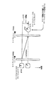
図23は、IEEE1394の通信レイヤの構成を示す図である。図23において、IEEE1394の通信レイヤは、物理層(Phyレイヤ)101、リンク層(Linkレイヤ)102、トランザクション層(Transactionレイヤ)103の3層と、シリアルバスマネージメント104とから構成される。
【0005】
Phyレイヤ101は、送受信する電気信号とLinkレイヤとの間で信号処理を行うレイヤである。Phyレイヤ101は、コネクタ、ケーブルなどの機械的インターフェースの規定、Linkレイヤ102が使用する論理信号のアナログディジタル変換を行うエンコードおよびデコード、通信信号の電気レベルを決めるシグナルレベルなどの電気的インターフェースの規定、通信ノード決定のためのアービトレーション、通信ロックの再同期、バスの初期化検出などを行っている。
【0006】
Linkレイヤ102は、Phyレイヤ101とTransactionレイヤ103との間で信号処理を行うレイヤである。Linkレイヤ102は、アドレス割当、データのチェック、データのフレーム分けを行うパケット送受信、サイクルのコントロールを行っている。なお、Isochronousデータは、Transactionレイヤを経由せずに、データが処理される。
【0007】
Transactionレイヤ103は、上位アプリケーションとLinkレイヤ102との間で信号処理を行うレイヤである。Transactionレイヤ103は、データの読み出し、書き込みなどの処理を行う。すなわち、Transactionレイヤ103は、Linkレイヤ102の処理を利用して、リクエストパケットの送信とレスポンスパケットの受信を行うことによって、指定されたノードとアドレスに対する1つの通信処理を行っている。また、逆に、リクエストパケットの受信とレスポンスパケットの送信という、他のノードから自ノードへの通信処理を行っている。
【0008】
シリアルバスマネージメント104は、3つのレイヤ全体の制御を行っている。なお、典型的な通信レイヤの実装としては、Phyレイヤ101とLinkレイヤ102とをハードウェアで構成し、Transactionレイヤ103とシリアルバスマネージメント104をファームウェアで構成する。
【0009】
IEEE1394のAsynchronous通信は、非同期に、データの通信を行う際に用いられる。Asynchronous通信では、相手ノードに確実にパケットを送信することを保証し、送信の遅延時間は保証しない。送信ノードは、ヘッダ情報と実データとを指定先のノードに送信し、受信ノードは、Acknowledgeパケットを返信することで、パケットを受け取ったことを知らせる。
【0010】
IEEE1394のIsochronous通信は、一種の同期通信であり、動画や音声などの伝送に適している。Isochronous通信では、125μsec毎にデータ転送が完了することを保証する。Isochronousパケットの送信ノードは、特定のノードに送信するのではなく、0〜63までのチャネル番号を使用してバス全体に送信し、受信ノードは、Acknowledgeパケットを返信しない。Isochronousパケットのヘッダは、6ビットのチャネル番号を使用することで、パケットを識別できるため、Asynchronousパケットのヘッダのように、64ビットのアドレス空間を使うのに比べて単純化されており、ヘッダ情報を少なくすることができる。受信ノードは、自ノードが受信したいチャネル番号のIsochronousパケットを選択して取り込む。送信ノードと受信ノードとが同じチャネル番号を使ってデータの送受信を行うことで、Isochronous通信が確立できる。
【0011】
図24に示すように、Isochronous通信とAsynchronous通信とは混在できる。1サイクル125μsecのうち、最大で100μsecをIsochronous通信に使用し、残りをAsynchronous通信に使用する。なお、パケット転送速度によって、Asynchronousパケットのデータペイロードの最大値が決定されているのは、Asynchronousデータの伝送時間が長すぎて、Isochronous通信を保証できなくなるのを回避するためである。
【0012】
Isochronous転送時間帯は、Isochronous通信を行う帯域であり、Asynchronous転送時間帯は、Asynchronous通信を行う帯域である。図24に示すように、Isochronous通信が常にAsynchronous通信よりも先に開始され、Isochronous通信を保証することができる。1サイクルでは、サイクルスタートパケットDSが送信された後に、図24では、Isochronous転送時間帯において、チャネルCH1のデータパケットD1およびチャネルCH3のデータパケットD2が伝送される。その後、Asynchronous転送時間帯において、データパケットD3,D4が伝送されるが、各データパケットD3,D4には、AcknowledgeパケットDAが返送される。
【0013】
IEEE1394の各ノードのうち、アイソクロナス(Isochronous)能力のあるノードが搭載するLinkレイヤは、バスとクロック同期するためのCYCLE_TIMEレジスタを実装し、このCYCLE_TIMEレジスタの内容を最新にするためのタイマを有している。このタイマをサイクルタイマと呼ぶ。このサイクルタイマの時刻は、サイクルスタート(Cycle Start)パケットによって設定される。また、IEEE1394では、このサイクルスタートパケットを発信するノードのことを、サイクルマスタと呼び、このサイクルマスタ以外のノードは、サイクルスレーブと呼ばれる。
【0014】
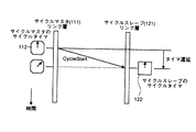
すなわち、図25および図26に示すように、サイクルマスタ111,131が有するサイクルタイマ112,132の時刻をサイクルスタートパケット「CycleStart」に乗せて各ノード(サイクルスレーブ)121,141,151に伝えることによって、各ノード121,141,151が有するサイクルタイマ122,142,152の時刻がサイクルマスタ111,131が有するサイクルタイマ112,132と同じ時刻に設定される。
【0015】
IEEE1394を利用したリアルタイムデータ転送は、Isochronousパケットによって伝送されるが、サイクルタイマを基準にして、送信側と受信側でデータの同期を取っている。同期の方法としてIsochronousパケットにタイムスタンプを入れたりする。
【0016】
【発明が解決しようとする課題】
しかしながら、実際には伝送遅延があるため、送信側のノードと受信側のノードのサイクルタイマは厳密に同じ時刻にはならない。すなわち、応答ノードがサイクルスタートパケットを受信してサイクルタイマの時刻を設定した瞬間には、要求ノードのサイクルタイマの時刻はその分だけ既に進んでおり、伝送遅延によって、送信側のノードと受信側のノードとの間の同期が精度良くとれないことになる。
【0017】
特に、IEEE1394によって接続されたネットワークを用いた制御システムを考えた場合、コントローラとサーボドライブとは、これらサイクルタイマを基準として同期制御を実現することになる。しかしながら、この制御システムに対しては、高速高精度、特に同期制御の高速高精度が要求されており、そのようなコントローラとサーボドライブとの間のタイマ遅延が、制御の高速高精度、特に同期制御の高速高精度に大きな影響を与えてしまうという問題点があった。
【0018】
この発明は上記に鑑みてなされたもので、送信側のノードと受信側のノードとが有するサイクルタイマのタイマ遅延を補償し、特にIEEE1394をコントローラとサーボドライバとの間のオープンなインタフェースとして使用した場合でも、高速高精度な制御、特に同期制御の高速高精度を実現することができるIEEE1394を用いた同期システムを得ることを目的とする。
【0019】
【課題を解決するための手段】
上記目的を達成するため、この発明にかかるIEEE1394を用いた同期システムは、IEEE1394を用いて接続されたネットワーク内の各ノード間の同期をとるIEEE1394を用いた同期システムにおいて、前記各ノードが有する各サイクルタイマ同士の遅延ずれ量を計測するサイクルタイマ遅延計測手段と、前記サイクルタイマ遅延計測手段が計測した遅延ずれ量をもとに前記各サイクルタイマ同士の遅延ずれを補正するサイクルタイマ遅延補正手段とを備え、前記サイクルタイマ遅延計測手段は、要求ノードから応答ノードに対して Read パケットを送信し、該応答ノードのサイクルタイマ値を読み取り、この読み取ったサイクルタイマ値を含む ReadResponse パケットを前記要求ノードが受信し、この受信したサイクルタイマ値と要求ノードのサイクルタイマ値との差をもとに前記遅延ずれ量を算出することを特徴とする。
【0020】
この発明によれば、IEEE1394を用いて接続されたネットワーク内の各ノード間の同期をとる際、サイクルタイマ遅延計測手段が、前記各ノードが有する各サイクルタイマ同士の遅延ずれ量を計測し、要求ノードから応答ノードに対して Read パケットを送信し、該応答ノードのサイクルタイマ値を読み取り、この読み取ったサイクルタイマ値を含む ReadResponse パケットを前記要求ノードが受信し、この受信したサイクルタイマ値と要求ノードのサイクルタイマ値との差をもとに前記遅延ずれ量を算出するようにしていると共に、サイクルタイマ遅延補正手段が、前記サイクルタイマ遅延計測手段が計測した遅延ずれ量をもとに前記各サイクルタイマ同士の遅延ずれを補正するようにしている。
【0031】
つぎの発明にかかるIEEE1394を用いた同期システムは、上記の発明において、前記要求ノードは、前記Readパケットを送信し、前記ReadResponseパケットが返送される一連のシーケンスが、同一のアシンクロナス転送が行われている時間帯である同一のAsynchronous転送時間帯で完了するか否かを判定する判定手段を備え、前記判定手段が、一連のシーケンスが同一のAsynchronous転送時間帯で完了すると判定した場合に、Readパケットを前記応答ノードに送出することを特徴とする。
【0032】
この発明によれば、前記要求ノードの判定手段が、前記Readパケットを送信し、前記ReadResponseパケットが返送される一連のシーケンスが、同一のアシンクロナス転送が行われている時間帯である同一のAsynchronous転送時間帯で完了するか否かを判定し、前記要求ノードが、前記判定手段が同一のAsynchronous転送時間帯で完了すると判定した場合に、Readパケットを前記応答ノードに送出するようにし、ReadResponseパケットが同一のAsynchronous転送時間帯内で返送されるようにしている。
【0033】
つぎの発明にかかるIEEE1394を用いた同期システムは、上記の発明において、前記応答ノードの上位層は、アシンクロナス転送が行われている時間帯であるAsynchronous転送時間帯であるか否かを判定する判定手段を備え、前記判定手段がAsynchronous転送時間帯であると判定した場合に、前記上位層が前記ReadResponseパケットを送信バッファに蓄えることを特徴とする。
【0034】
この発明によれば、前記応答ノードの上位層の判定手段が、アシンクロナス転送が行われている時間帯であるAsynchronous転送時間帯であるか否かを判定し、前記判定手段がAsynchronous転送時間帯であると判定した場合に、前記上位層は前記ReadResponseパケットを送信バッファ(TX_FIFO)に蓄えることで、前記ReadResponseパケットは、送信バッファ長くとどまることなく、直ちに要求ノードに返送されるようにしている。
【0035】
つぎの発明にかかるIEEE1394を用いた同期システムは、上記の発明において、前記応答ノードのリンク層は、パケットの送出直前に該パケットにデータを書き込む書込手段を備え、前記ReadResponseパケットがリンク層バッファから送出される直前に前記書込手段によって該ReadResponseパケットに当該応答ノードのサイクルタイマ値を書き込むことを特徴とする。
【0036】
この発明によれば、前記応答ノードのリンク層の書込手段が、前記ReadResponseパケットがリンク層バッファから送出される直前に該ReadResponseパケットに当該応答ノードのサイクルタイマ値を書き込むようにしている。
【0037】
つぎの発明にかかるIEEE1394を用いた同期システムは、上記の発明において、各ノードは、前記遅延ずれ量を記憶するサイクルタイマ遅延記憶手段を備えたことを特徴とする。
【0038】
この発明によれば、各ノードのサイクルタイマ遅延記憶手段が、前記遅延ずれ量を記憶し、少なくとも他のノードからのアクセスによって遅延ずれ量を獲得できるようにしている。
【0039】
つぎの発明にかかるIEEE1394を用いた同期システムは、上記の発明において、前記サイクルタイマ遅延記憶手段は、全てのノード間の遅延ずれ量をデータテーブル形式で記憶することを特徴とする。
【0040】
この発明によれば、前記サイクルタイマ遅延記憶手段が、全てのノード間の遅延ずれ量をデータテーブル形式で記憶するようにしている。
【0041】
つぎの発明にかかるIEEE1394を用いた同期システムは、上記の発明において、前記サイクルタイマ遅延記憶手段は、サイクルマスタとしてのノードに設けられたことを特徴とする。
【0042】
この発明によれば、前記サイクルタイマ遅延記憶手段を、サイクルマスタとしてのノードに設けるようにしている。
【0043】
つぎの発明にかかるIEEE1394を用いた同期システムは、上記の発明において、前記ネットワークの構成の変化を判別するネットワーク構成変化判別手段をさらに備え、前記ネットワーク構成変化判別手段がネットワークの構成に変化があったと判別した場合、該ネットワークの再構成後、前記サイクルタイマ遅延計測手段がサイクルタイマ同士の遅延ずれ量を計測し、前記サイクルタイマ遅延補正手段が該遅延ずれ量をもとにサイクルタイマ同士の遅延ずれを補正する処理を一回行うことを特徴とする。
【0044】
この発明によれば、ネットワーク構成変化判別手段が、前記ネットワークの構成の変化を判別し、前記ネットワーク構成変化判別手段がネットワークの構成に変化があったと判別した場合、該ネットワークの再構成後、前記サイクルタイマ遅延計測手段がサイクルタイマ同士の遅延ずれ量を計測し、前記サイクルタイマ遅延補正手段が該遅延ずれ量をもとにサイクルタイマ同士の遅延ずれを補正する処理を一回行うようにしている。
【0045】
つぎの発明にかかるIEEE1394を用いた同期システムは、上記の発明において、前記ネットワーク構成変化判別手段は、サイクルマスタとしてのノードに設けられたことを特徴とする。
【0046】
この発明によれば、前記ネットワーク構成変化判別手段を、サイクルマスタとしてのノードに設けるようにしている。
【0047】
つぎの発明にかかるIEEE1394を用いた同期システムは、上記の発明において、前記サイクルタイマ遅延計測手段および前記サイクルタイマ遅延補正手段は、ノード間の同期を用いる所定のノードに設けられたことを特徴とする。
【0048】
この発明によれば、前記サイクルタイマ遅延計測手段および前記サイクルタイマ遅延補正手段を、ノード間の同期を用いる所定のノードに設けるようにしている。
【0049】
つぎの発明にかかるIEEE1394を用いた同期システムは、上記の発明において、前記遅延ずれ量を伝送するサイクルタイマ遅延伝送手段をさらに備え、同期の基準となるサイクルタイマを有するサイクルマスタのノードは、前記サイクルタイマ遅延計測手段および前記サイクルタイマ遅延伝送手段を有し、前記サイクルマスタのノード以外の所定のノードは、前記サイクルタイマ遅延補正手段を有し、前記サイクルマスタのノードが、該ノードが計測した遅延ずれ量を前記所定のノードに伝送し、あるいは該ノードが計測した遅延ずれ量をデータテーブルに記憶し、前記所定のノードが前記サイクルマスタのノードから該遅延ずれ量を取得し、その後所定のノードに伝送された遅延ずれ量あるいは取得した遅延ずれ量をもとに該ノードのサイクルタイマの遅延ずれを補正することを特徴とする。
【0050】
この発明によれば、同期の基準となるサイクルタイマを有するサイクルマスタのノードが、該ノードが計測した遅延ずれ量を前記サイクルタイマ遅延伝送手段によって前記所定のノードに伝送し、あるいは該ノードが計測した遅延ずれ量をデータテーブルに記憶し、前記所定のノードが前記サイクルマスタのノードから該遅延ずれ量を取得し、その後所定のノードに伝送された遅延ずれ量あるいは取得した遅延ずれ量をもとに該ノードのサイクルタイマの遅延ずれを補正するようにしている。
【0051】
つぎの発明にかかるIEEE1394を用いた同期システムは、上記の発明において、前記サイクルタイマ遅延補正手段は、サイクルスタートパケットを受信した際に、遅延ずれ量をもとにサイクルタイマ値を設定することを特徴とする。
【0052】
この発明によれば、前記サイクルタイマ遅延補正手段が、サイクルスタートパケットを受信した際に、遅延ずれ量をもとにサイクルタイマ値を設定するようにしている。
【0053】
つぎの発明にかかるIEEE1394を用いた同期システムは、上記の発明において、前記サイクルタイマ遅延補正手段は、上位層がサイクルタイマ値の使用時に、前記遅延ずれ量を用いて遅延ずれを補正することを特徴とする。
【0054】
この発明によれば、前記サイクルタイマ遅延補正手段が、上位層がサイクルタイマ値の使用時に、前記遅延ずれ量を用いて遅延ずれを補正するようにしている。
【0055】
つぎの発明にかかるIEEE1394を用いた同期システムは、上記の発明において、前記所定のノードは、第2のサイクルタイマをさらに備え、前記サイクルタイマ遅延補正手段は、任意のタイミングで遅延ずれ量を用いて前記遅延ずれを補正したサイクルタイマ値を前記第2のサイクルタイマに設定することを特徴とする。
【0056】
この発明によれば、所定のノードの前記サイクルタイマ遅延補正手段が、任意のタイミングで遅延ずれ量を用いて前記遅延ずれを補正したサイクルタイマ値を第2のサイクルタイマに設定するようにしている。
【0057】
つぎの発明にかかるIEEE1394を用いた同期システムは、上記の発明において、前記サイクルマスタのノードは、タイムスタンプを生成するタイムスタンプ生成手段を備え、前記所定のノードは、タイムスタンプが示す時刻を監視するタイムスタンプ時刻監視手段を備え、前記サイクルタイマ遅延補正手段は、前記遅延ずれ量をもとに、前記サイクルマスタのノードから送られた前記タイムスタンプのタイムスタンプ値を更新し、前記タイムスタンプ時刻監視手段は、前記更新されたタイムスタンプ値が示す時刻を監視することを特徴とする。
【0058】
この発明によれば、前記サイクルタイマ遅延補正手段が、前記遅延ずれ量をもとに、前記サイクルマスタのノードから送られた前記タイムスタンプのタイムスタンプ値を更新し、前記タイムスタンプ時刻監視手段が、前記更新されたタイムスタンプ値が示す時刻を監視するようにしている。
【0059】
つぎの発明にかかるIEEE1394を用いた同期システムは、上記の発明において、前記サイクルタイマ遅延計測手段および前記サイクルタイマ遅延補正手段は、サイクルマスタとしてのノードに設けられたことを特徴とする。
【0060】
この発明によれば、前記サイクルタイマ遅延計測手段および前記サイクルタイマ遅延補正手段を、サイクルマスタとしてのノードに設けるようにしている。
【0061】
つぎの発明にかかるIEEE1394を用いた同期システムは、上記の発明において、前記遅延ずれ量を転送するサイクルタイマ遅延伝送手段をさらに備え、サイクルマスタのノードは、前記サイクルタイマ遅延補正手段を有し、前記サイクルマスタのノード以外の所定のノードは、前記サイクルタイマ遅延計測手段および前記サイクルタイマ遅延伝送手段を有し、前記所定のノードが、該所定のノードで計測した遅延ずれ量を前記サイクルマスタのノードに伝送し、あるいは前記所定のノードから遅延ずれ量を取得し、その後該所定のノードに伝送された遅延ずれ量あるいは取得した遅延ずれ量をもとに前記サイクルマスタのノードのサイクルマスタの遅延ずれを補正することを特徴とする。
【0062】
この発明によれば、前記所定のノードが、該所定のノードで計測した遅延ずれ量を前記サイクルマスタのノードに伝送し、あるいは前記所定のノードから遅延ずれ量を取得し、その後該所定のノードに伝送された遅延ずれ量あるいは取得した遅延ずれ量をもとに前記サイクルマスタのノードのサイクルマスタの遅延ずれを補正するようにしている。
【0063】
つぎの発明にかかるIEEE1394を用いた同期システムは、上記の発明において、前記サイクルマスタのノードは、タイムスタンプを生成するタイムスタンプ生成手段を備え、前記所定のノードは、タイムスタンプが示す時刻を監視するタイムスタンプ時刻監視手段を備え、前記サイクルタイマ遅延補正手段は、前記遅延ずれ量をもとに、前記タイムスタンプ生成手段が生成したタイムスタンプのタイムスタンプ値を更新することを特徴とする。
【0064】
この発明によれば、前記サイクルタイマ遅延補正手段が、前記遅延ずれ量をもとに、自サイクルマスタのノードの前記タイムスタンプ生成手段が生成したタイムスタンプのタイムスタンプ値を更新し、この更新したタイムスタンプ値を含むデータを所定のノードに伝送するようにしている。
【0065】
つぎの発明にかかるIEEE1394を用いた同期システムは、上記の発明において、請求項1〜23のいずれか一つに記載したIEEE1394を用いた同期システムは、サーボドライブ装置とこれを制御するコントローラとからなる制御システムであることを特徴とする
【0066】
この発明によれば、請求項1〜23のいずれか一つに記載したIEEE1394を用いた同期システムを、サーボドライブ装置とこれを制御するコントローラとからなる制御システムに適用している。
【0067】
つぎの発明にかかるIEEE1394を用いた同期システムは、上記の発明において、前記コントローラは、サイクルマスタであることを特徴とする。
【0068】
この発明によれば、前記コントローラを、サイクルマスタとし、効率的な遅延ずれ量の計測および補正ができるようにしている。
【0069】
【発明の実施の形態】
以下、添付図面を参照して、この発明にかかるIEEE1394を用いた同期システムの好適な実施の形態について説明する。
【0070】
実施の形態1.
まず、この発明の実施の形態1について説明する。この実施の形態1では、ピングパケットを利用してサイクルタイマ遅延を推定し補償するようにしている。P1394aでは、最適なGap_Count値を計算し設定するために、ピング(Ping)パケットが定義されている。Gap(ギャップ)とは、例えば図24に示したデータパケットD2,D3間などの時間であり、バスがアイドル状態となっている時間をいい、このギャップが長くなれば、バスがアイドルとなっている時間が長くなり、実際にパケットが流れる時間が制限され、一方、キャップを極端に短くすると、トポロジの構成で、物理層のホップ数が多い場合や接続されるノードが多い場合には通信が行えなくなってしまうため、ギャップは最適化される。
【0071】
P1394aでは、あるノード(バスマネージャ)から他のノードにこのピングパケット送信すると、このピングパケットを受信した送り先のノードの物理層(Phyレイヤ)は、Self_IDパケットを送り返す仕様になっており、ピングパケットが送出されてから、Self_IDパケットが返送されて戻ってくるまでの時間を測ることによって、2つのノード間の遅延時間がわかるようになっている。そして、上述したように、P1394aでは、この遅延時間をもとに、最適なGap_Count値を計算し設定することができるようになった。ルート以外は、すべてリンク層(Linkレイヤ)がなくても、このPingパケットに応答できるため、物理層だけで構成されるリピータでも遅延時間を知ることができ、トポロジが変わっても最適なGap_Count値を計算することができる。なお、このPingパケットは、IEEE1394−1995規格にはないが、P1394a規格で検討中である。
【0072】
さて、この実施の形態1では、Pingパケットを利用してサイクルタイマ遅延を推定し、補償する。IEEE1394の物理層のパケットリピート回路は、対称なため、図1に示すように、要求ノードN1の物理層から送られたPingパケットが応答ノードN2の物理層に到達するまでの伝送遅延t1は、応答ノードN2の物理層から返送されたSelf_IDパケットが要求ノードN1の物理層に到達するまでの伝送遅延t2とほぼ等しい。すなわち、
伝送遅延t1≒伝送遅延t2
とみなすことができる。この結果、図1に示すように、要求ノードN1の物理層がPingパケットを送出してからSelf_IDパケットを受信するまでの時間を所要時間tとすると、伝送遅延t1は、
t1(伝送遅延)≒(t(所要時間)−RESPONSE_TIME)/2
として求めることができる。この伝送遅延t1がそのまま、要求ノードN1が保持するサイクルタイマと応答ノードN2が保有するサイクルタイマとの間の遅延として考えることができる。なお、「RESPONSE_TIME」に実際どのぐらいの時間がかかったのかは、この手法では分からないが、「RESPONSE_TIME」の最小値および最大値は、パラメータで指定されており(Cable interface timing constants)、既知である。したがって、たとえば、
RESPONSE_TIME≒(最大値+最小値)/2
として「RESPONSE_TIME」を求めてもよい。実験的に、「RESPONSE_TIME」に実際どのぐらいの時間がかかっているのかがわかっていれば、最大値と最小値の平均の代わりに適当な重み付き平均、たとえば、係数wを用いて
RESPONSE_TIME≒(w×最大値+(1−w)×最小値)/2
とし、これによって一層精度の良い「RESPONSE_TIME」を求めることができる。
【0073】
また、Pingパケットを送信し、Self_IDパケットが返ってくるまでの所要時間tを計測する代わりに、RemoteAccessパケットを送信し、RemoteReplyパケットが返ってくるまでの時間を計測し、この時間を所要時間tとしてもよい。また、RemoteCommandパケットを送信し、RemoteConfirmationパケットが返ってくるまでの時間を計測し、この時間を所要時間tとしてもよい。これらパケットは、ほぼ同じ振る舞い、すなわち物理層が返送するので、これらのどのパケットを用いても良い。これらのパケットは、サイクルマスタ、サイクルスレーブに関わらず、全てのノードが任意にノードに対して送信することができるので、任意のノード間の遅延を任意のノードが必要に応じて計測することができる。
【0074】
このノード間の遅延(タイマ遅延)は各ノード間で各々異なるので、各ノード間の全ての場合についてタイマ遅延の補償を行うのが望ましい。しかしながら、タイマ遅延計測を頻繁に行えば、タイマ遅延計測のためのパケットが増えることになり、その分だけネットワークのトラフィックが増えることになり、重要なパケットの伝送の妨げになりかねない。
【0075】
タイマ遅延は、ネットワークの構成(トポロジ)が変わらない限り同じであるから、タイマ遅延補償は、基本的にネットワークの構成(再構成)が行われた後の最初の1回だけ行えば良いので、バスリセットなどのネットワークの再構成を含むネットワークの構成が行われたことを検出し、かつサイクルスタートパケットによるサイクルタイマ設定が行われた後に、最初に1回だけタイマ遅延計測のためのパケットを流してタイマ遅延補償を行う。
【0076】
このため、ネットワーク上のある1つノード、たとえばサイクルマスタ、制御システムの場合はコントローラが、ネットワーク構成変化判別手段を保有する必要がある。ネットワーク構成変化判別手段は、ネットワークが再構成を判別した場合、タイマ遅延補償を行う指令を他のノードへ伝える。あるいは、ネットワーク構成変化判別手段を、必ずサイクルマスタ(制御システムの場合はコントローラ)が保有するようにし、サイクルマスタ自体が保有するデータテーブルにタイマ遅延を記憶するなどの一連のタイマ遅延に関する作業をすべてサイクルマスタによって管理するようにしても良い。
【0077】
この実施の形態1によれば、IEEE1394の仕様(P1394a既存の仕様)の範囲内で、各ノードが有するサイクルタイマのタイマ遅延を補償することで、IEEE1394を任意の用途に利用する場合でも、高精度な同期を実現することが可能となる。さらには、IEEE1394をコントローラとサーボドライバと間のオープンなインタフェースとして使用した場合でも、コントローラとサーボドライブとの間、あるいはサーボドライブ間同士のタイマ遅延を補償することが可能となり、高速高精度な制御を実現することができる。また、タイマ遅延計測に使用されるパケットは、サイクルマスタのみが使用できるものではなく、全てのノードが等しく使用できるため、任意のノード間のタイマ遅延を計測することが可能である。
【0078】
実施の形態2.
つぎに、この発明の実施の形態2について説明する。上述した実施の形態1では、RESPONSE_TIMEに、実際どのぐらいの時間がかかったのかが分からないため、おおよそのタイマ遅延を推定するようにしていたが、この実施の形態2では、真に正確なタイマ遅延を測定できるようにし、特にタイマ遅延の誤差が大きな影響を及ぼす、コントローラとサーボドライブとを有する制御システムにIEEE1394を用いる場合であっても、支障のないようにしている。
【0079】
IEEE1394では、リード(Read)パケットを使って、応答ノードが有するサイクルタイマのサイクルタイマ値を読み込むことができる。この読み込みによって取得されたサイクルタイマ値と要求ノードが有するサイクルタイマのサイクルタイマ値との差から、タイマ遅延を計測すれば、実際のタイマ遅延を測定することが可能であるように思われる。
【0080】
しかし、実際には、Readパケットに対するレスポンス(ReadResponse)パケットは、応答ノードの上位層(トランザクション層およびそれより上位の層)がReadResponseパケットを送信バッファ(TX_FIFO)に蓄える際、ReadResponseパケットにサイクルタイマ値を書き込むため、その後、実際に応答ノードのリンク層から送信されるまでの時間は一定値ではなく、Readパケットとこれに対するReadResponseパケットとを用いても、正確なタイマ遅延を測定することはできない。
【0081】
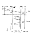
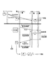
送信バッファに蓄えられる時間が長くなる理由は、このリード処理が非同期(ASYNC)処理であり、ReadパケットおよびReadResponseパケットが非同期(ASYNC)パケットであるから、Asynchronous転送時間帯でしか送信することができないために、ReadResponseパケットが送信バッファに蓄える時がAsynchronous転送時間帯であれば、図2に示すように、送信バッファに滞留する時間は一瞬であって、直ちに送信されるのに対し、図3に示すように、ReadResponseパケットが送信バッファに送られた時がIsochronous転送時間帯であれば、Isochronous転送時間帯が終了してAsynchronous転送時間帯になって送信可能となるまで、ReadResponseパケットが送信バッファに滞留するからである。
【0082】
この送信バッファに滞留する時間の差異を解消するには、いくつかの方策がある。その第1の方策は、応答ノードN2がReadパケットを受け付けてReadResponseパケットを送出するまでの一連の動作が、常に図2に示すように、同一のAsynchronous転送時間帯中に行われればよいのであるから、要求ノードN1が予め、Readパケットを送信してReadResponseパケットが返送されるまでの一連の動作が、同一のAsynchronous転送時間帯中に行われるかどうかを判定部1が判定し、同一のAsynchronous転送時間帯中に行われると判断した場合に、要求ノードがReadパケットを応答ノードに送信すればよい。
【0083】
基本的に、タイマ遅延計測のためのパケットは、ネットワーク構築後の初期の段階で行われるので、ネットワーク構築後の初期の段階においては、制御システムが制御するためのデータ転送はなく、すなわちトラフィックは少なく、また、応答ノードN2の上位層でも特別なアプリケーションが作動していないので、タイマ遅延計測のためのパケットの要求に対してすばやく応答するであろう。
【0084】
したがって、同一のAsynchronous転送時間帯中に上述した一連の動作が行われるネットワーク構築後の初期の段階などに、タイマ遅延計測のためのパケットを要求ノードN1が応答ノードN2に送出すれば、Readパケットを受け付けてからReadResponseパケットを送出するまでの処理時間は、容易に推定することができる。この場合、上位層における処理時間の推定は、上述した実施の形態1による遅延計測を用いることができる。また、この場合、上述した一連の動作が他のトラフィックに邪魔される可能性は少ないため、信頼度の高い測定が可能となる。
【0085】
この第1の方策によれば、既存のプロトコルをそのまま使用し、送信側である要求ノードN1の上位層に、Readパケットを送信してReadResponseパケットが返送されるまでの一連の動作が同一のAsynchronous転送時間帯中に行われるかどうかを判定する判定部1を設けるのみで、この一連の動作が同一のAsynchronous転送時間帯内で行われるので、正確なタイマ遅延補償が可能となる。
【0086】
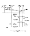
第2の方策としては、図4に示すように、応答ノードN1の上位層が、ReadResponseパケットを送信バッファに蓄えるタイミングをAsynchronous転送時間帯の間に行えば良い。すなわち、応答ノードN2の上位層が、Asynchronous転送時間帯となるまで待って、ReadResponseパケットをリンク層に送出するようにする。なお、上位層は、下位のリンク層からの割り込み信号によって現在の通信伝送路の状態がIsochronous転送時間帯であるかAsynchronous転送時間帯であるかを知ることができる。これによって、Asynchronous転送時間帯待ちの既知の時間を上位層の処理時間に加えるのであるので、要求ノードN1と応答ノードN2との間のタイマ遅延を確実に測定することができる。
【0087】
第2の方策によれば、既存のプロトコルをそのまま使用し、受信側ノードである応答ノードN2の上位層に、現在の通信伝送路の状態がIsochronous転送時間帯であるかAsynchronous転送時間帯であるかを判定する判定部を設けるだけで、ReadパケットとReadResponseパケットとが同一のAsynchronous転送時間帯内であろうとなかろうとに関わらず、正確なタイマ遅延補償を行うことができる。
【0088】
第3の方策としては、図5に示すように、ReadResponseパケットをリンク層から送出する時に、書込部3がこのReadResponseパケットにサイクルタイマ値を書き込むようにする。すなわち、上位層からリンク層にReadResponseパケットが送られたときにサイクルタイマ値を書き込むのではなく、ReadResponseパケットがリンク層から送出される瞬間に、このReadResponseパケットにサイクルタイマ値を書き込むようにする。
【0089】
IEEE1394において、サイクルスタートパケットによるサイクルタイマ設定では、サイクルマスタから送られてくるサイクルスタートパケットを応答ノードN2がリンク層で受け取った瞬間に、該サイクルスタートパケットに記述されているサイクルタイマ値を自ノードのサイクルタイマ値として設定する機構を既に備えている。
【0090】
しかしながら、この機構は、サイクルスタートパケットに固有の機構であって、第3の方策を行う機構は、IEEE1394には定義されておらず、新規にこの機構を追加するものである。なお、第1の方策あるいは第2の方策のように、送信バッファに蓄えられてから直ちに送信されると言っても若干の時間はかかるものであるが、この第3の方策によれば、この若干の時間の誤差すら発生せず、一層、正確な遅延測定が可能になる。
【0091】
第3の方策によれば、既存のプロトコルをそのまま使用し、受信側ノードである応答ノードのリンク層に、ReadResponseパケットがリンク層から送出される瞬間にこのReadResponseパケットにサイクルタイマ値を書き込む書込部3を設けるだけで、ReadパケットとReadResponseパケットとが同一のAsynchronous転送時間帯内であろうとなかろうとに関わらず、正確なタイマ遅延補償が可能となる。
【0092】
この実施の形態2によれば、IEEE1394の仕様(IEEE1394−1995既存の仕様)の範囲内で、各ノードが有するサイクルタイマのタイマ遅延を補償することで、IEEE1394を任意の用途に利用する場合でも、高精度な同期を実現することが可能である。さらには、IEEE1394をコントローラとサーボドライバとの間のオープンなインタフェースとして使用した場合でも、コントローラとサーボドライブとの間あるいはサーボドライブ間同士のタイマ遅延を補償することが可能となり、高速高精度な制御を実現できる。また、タイマ遅延計測に使用されるパケットは、サイクルマスタのみが使用できるものではなく、全てのノードが等しく使用できるため、任意のノード間のタイマ遅延を計測することが可能である。
【0093】
実施の形態3.
つぎに、この発明の実施の形態3について説明する。この実施の形態3では、上述した実施の形態1または実施の形態2によって測定されたタイマ遅延をもとに、タイマ遅延の補償を行うものである。なお、この実施の形態3では、サイクルスレーブ側がサイクルスタートパケット受信時にタイマ遅延を補償する場合について説明する。
【0094】
まず、サイクルスレーブは、サイクルスレーブ自身が有するサイクルタイマ値と、サイクルマスタが有するサイクルタイマ値との遅延ずれを知っている必要がある。この遅延ずれを取得するためのいくつかの態様としては、たとえば、つぎの9つの遅延ずれ取得態様がある。
【0095】
第1の遅延ずれ取得態様は、図6に示すように、サイクルマスタNMが任意のサイクルスレーブNSとの間の遅延ずれを測定し(S11)、この遅延ずれを当該サイクルスレーブNSに伝える(S12)ことによって当該サイクルスレーブNSが遅延ずれを取得する態様である。
【0096】
第2の遅延ずれ取得態様は、図7に示すように、サイクルマスタNMが任意のサイクルスレーブNSとの間の遅延ずれを測定し(S21)、この遅延ずれをサイクルマスタNMが有する遅延記憶手段に記憶し(S22)、任意のサイクルスレーブNSがサイクルマスタNMに対してこの遅延記憶手段をアクセスし、遅延ずれを読み取り(S23)、当該サイクルスレーブNSが遅延ずれを取得する態様である。
【0097】
第3の遅延ずれ取得態様は、図8に示すように、任意のサイクルスレーブNSがサイクルマスタNMとの間の遅延ずれを測定し(S31)、これによって遅延ずれを取得する態様である。
【0098】
この第1〜第3の遅延ずれ取得態様によれば、サイクルスレーブNSは、サイクルマスタNMのタイマ値に厳密に一致するように補償することができる。
【0099】
第4の遅延ずれ取得態様は、図9に示すように、ある特定のサイクルスレーブNS1が、他の任意のサイクルスレーブNS2との間の遅延ずれを測定し(S41)、かつ、サイクルマスタNMとの間の遅延ずれを測定し(S42)、サイクルマスタNMと任意のサイクルスレーブNS2との間の遅延を算出し(S43)、この遅延を任意のサイクルスレーブNS2に伝える(S44)ことによって、当該任意のサイクルスレーブNS2が遅延ずれを取得する態様である。
【0100】
第5の遅延ずれ取得態様は、図10に示すように、ある特定のサイクルスレーブNS1が、他の任意のサイクルスレーブNS2との間の遅延ずれを測定し(S51)、かつ、サイクルマスタNMとの間の遅延ずれを測定し(S52)、サイクルマスタNMと任意のサイクルスレーブNS2との間の遅延を算出し(S53)、この算出した遅延を、特定のサイクルスレーブ自身が有する遅延記憶手段に記憶し(S54)、任意のサイクルスレーブNS2がこの遅延記憶手段をアクセスしてこの遅延を読み取り(S55)、これによって任意のサイクルスレーブNS2が遅延ずれを取得する態様である。
【0101】
第6の遅延ずれ取得態様は、図11に示すように、ある特定のサイクルスレーブNS1が、他の任意のサイクルスレーブNS2との間の遅延ずれを測定し(S61)、かつ、サイクルマスタNMとの間の各遅延ずれを測定し(S62)、これらの各遅延を特定のサイクルスレーブNS1自身が有する遅延記憶手段に記憶し(S63)、任意のサイクルスレーブNS2が特定のサイクルスレーブNS1をアクセスしてこれらの遅延を読み取り(S64)、その後サイクルマスタNMとの間の遅延を算出する(S65)態様である。
【0102】
上述した第4〜第6の遅延ずれ取得態様は、第1〜第3の遅延ずれ取得態様と同じ作用効果を有するが、やや複雑な取得態様となっている。
【0103】
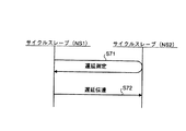
第7の遅延ずれ取得態様は、図12に示すように、ある特定のサイクルスレーブNS1が他の任意のサイクルスレーブNS2との間の遅延ずれを測定し(S71)、この遅延ずれを当該任意のサイクルスレーブNS2に伝送し(S72)、任意のサイクルスレーブNS2が遅延ずれを取得する態様である。
【0104】
第8の遅延ずれ取得態様は、図13に示すように、ある特定のサイクルスレーブNS1が他の任意のサイクルスレーブNS2との間の遅延ずれを測定し(S81)、この遅延ずれを特定のサイクルスレーブNS1自身が有する遅延記憶手段に記憶し(S82)、任意のサイクルスレーブNS2がこの遅延記憶手段にアクセスして遅延ずれを読み取る(S83)ことによって、任意のサイクルスレーブが遅延ずれを取得する態様である。
【0105】
第9の遅延ずれ取得態様は、図14に示すように、任意のサイクルスレーブNS2が、ある特定のサイクルスレーブNS1との間の遅延ずれを測定し(S91)、これによって任意のサイクルスレーブNS2が遅延ずれを取得する態様である。
【0106】
上述した第7〜第9の遅延ずれ取得態様によれば、ある特定のサイクルスレーブのタイマ値に厳密に一致するように他の任意のサイクルスレーブのタイマ値を補償することが可能となる。この場合、同じタイマ値を有していないのはネットワーク上ではサイクルマスタのみとなる。
【0107】
サイクルスレーブが自信の有するサイクルタイマ値と、基準となるノード(サイクルマスタの場合もあればサイクルスレーブの場合もある)が有するサイクルタイマ値の遅延ずれを、サイクルスレーブ自身で知ることができたならば、サイクルスレーブ側自身でタイマ遅延を補償することができる。このタイマ遅延補償態様には、つぎの3つの態様がある。以下に説明する3つの態様では、基準となるノードがサイクルマスタの場合について説明しているが、基準となるノードがサイクルスレーブの場合でも同様に実施できる。
【0108】
第1のタイマ遅延補償態様は、図15に示されるように、タイマ遅延量Δt11を考慮してサイクルタイマTM1のサイクルタイマ値を設定するものである。サイクルマスタNMが、サイクルスレーブNSに対し、サイクルスタートパケットによってサイクルマスタNMが有するサイクルタイマ値t10を伝送した際に、サイクルスレーブNS側がこのサイクルスタートパケットを受け取った時にサイクルタイマ値t10をそのままサイクルスレーブNS自身が有するサイクルタイマTM1のサイクルタイマ値t10と設定せずに、遅延ずれ量Δt11を考慮してサイクルタイマ値t12を設定する。すなわち、
t12(設定すべきサイクルタイマ値)
=t10(受け取ったサイクルタイマ値)+Δt11(タイマ遅延量)
となる。
【0109】
第2のタイマ遅延補償態様は、図16に示すように、サイクルスレーブNS側がサイクルスタートパケットを受け取った時にサイクルタイマ値t10をそのまま自サイクルスレーブNSが有するサイクルタイマ値t10として設定する点は、従来のタイマ設定と同じであるが、サイクルスレーブNS側の上位層(サイクルスレーブ側のアプリケーション)がサイクルタイマ値を使用する、すなわち読みにきた際におけるサイクルタイマ値t13に、遅延ずれ量を補正し、この補正したサイクルタイマ値t14を上位層が用いるようにする。この場合、遅延ずれ量が予め知っていれば、基本的にいつでもサイクルタイマ値を補償でき、この補償したサイクルタイマ値を用いることができる。すなわち、
t14(使用すべきサイクルタイマ値)
=t13(リンク層のサイクルタイマ値)+Δt11(タイマ遅延量)
となる。
【0110】
第3のタイマ遅延補償態様は、図17に示すように、サイクルスレーブNSは、サイクルタイマTM1とは別個に第2のサイクルタイマTM2を有する。サイクルタイマTM1には、受け付けたサイクルタイマ値をそのまま設定し、第2のサイクルタイマTM2には、任意のタイミング、たとえば時間的にクリティカルでないときに、タイマ遅延量Δt11を加味したタイマ遅延補償されたサイクルタイマ値が設定され、上位層は、このサイクルタイマ値を用いるようにしている。
【0111】
この実施の形態3によれば、IEEE1394の仕様(IEEE1394−1995既存の仕様)の範囲内で、各ノードが有するサイクルタイマのタイマ遅延を補償することで、IEEE1394を任意の用途に利用する場合でも、高精度な同期を実現することが可能である。また、すべてのノードがタイマ補償を必要としている訳ではないので、必要なノードだけが必要に応じて遅延計測補償を行えば良い。さらには、IEEE1394をコントローラとサーボドライバとの間のオープンなインタフェースとして使用した場合でも、コントローラとサーボドライブとの間、あるいはサーボドライブ間同士のタイマ遅延を補償することが可能となり、高速高精度な制御を実現できる。また、タイマ遅延補償はサーボ側で行うので、コントローラ部分に何の変更も必要ない。さらには、すべての被制御機器がタイマ補償を必要としている訳ではないので、必要なサーボノードだけが必要に応じて遅延計測補償を行えば良い。
【0112】
ところで、上述した第1のタイマ遅延補償態様は、単純であり、また、タイマを用いた割込は遅延を補償した時刻における割込となることから、正確である。しかし、IEEE1394の基幹に関わる部分であるリンク層を変更しなければならない。さらに、IEEE1394ではサイクルスタートパケットを受け取ってタイマ値を更新する際にタイマ値を戻してはならない、という規約がある。この実施の形態で、サイクルスレーブのサイクルタイマを基準としたならば、遅延ずれが負の値を持ち、タイマ遅延補償をする際にタイマ値を戻すノードが存在することがあるので、このような場合には、IEEE1394のこの規約を無視するか、あるいは、「基準となるサイクルスレーブのサイクルタイマ値+一定時間」をネットワーク上での基準時間とすることで、タイマ遅延補償をする際にタイマ値を戻すノードがないようにして、IEEE1394のこの規約を守るようにする、などの処置を行う必要がある。また、タイマ遅延補償を行うサイクルスレーブの上位層からみて、タイマがいつ更新されるかがわからない、すなわちサイクルスタートパケットがいつ送られてくるのかわからないため、タイマ遅延補償を行うサイクルスレーブの上位層において、時間を計測している最中など、時間に対してクリティカルな最中にタイマの更新が行われる可能性があり、クリティカルな最中にタイマの更新が行われた場合とそうでない場合とで誤差が生じてしまう。
【0113】
もともと、サイクルマスタが有するサイクルタイマとサイクルスレーブが有するサイクルタイマとは完全に特性が一致するとは限らないので、お互いのサイクルタイマの間に精度の差が存在し、サイクルスタートパケットによってサイクルスレーブのサイクルタイマを、サイクルマスタのサイクルタイマ値に合わせるのは、このサイクルタイマ間の精度差をなくすためである。しかしながら、たとえば、タイマ遅延補償を行うサイクルスレーブの上位層(の任意のアプリケーション)が、何か別の目的で時間計測などを、自身のサイクルタイマを使って行う場合、サイクルタイマの更新が起こらなければ、自身のサイクルタイマの精度の範囲内で、その時間計測の精度は保証されるが、その時間計測の途中でサイクルタイマの更新が起こってしまったら、その時間計測の精度は全く保証されないものになってしまう。もちろん、この誤差が問題のない範囲でシステムにIEEE1394を用いるのであれば、この第1のタイマ遅延補償態様はこのシステムに十分である。
【0114】
一方、第2のタイマ遅延補償態様では、IEEE1394に関わる変更は全くなく、上位層(アプリケーション)のみ変更すれば良いので、容易に実現が可能である。しかしながら、このタイマを使った割込は、遅延を補償したタイマが発生する割込とはならない。この代替手段としてアプリケーションからタイマをポーリングして正確な時刻の割込を実現することも可能である。ただし、ポーリングによる負荷が生じることになる。さらに、第1のタイマ遅延補償態様と同様に、サイクルタイマ値の更新がいつ起こるか判らないことによる、タイマの精度の保証の問題が残る。ポーリングによる負荷や、タイマ更新に関わる誤差が問題ない範囲で用いるシステムに適用するのであれば、この第2のタイマ遅延補償態様は、十分用いることができる。
【0115】
また、第3のタイマ遅延補償態様では、第1および第2のタイマ遅延補償態様で問題となっていたタイマ更新に関わる誤差の保証問題を解決することができる。この第3のタイマ遅延保証態様では、サイクルタイマ値にタイマ遅延量を考慮したサイクルタイマ値を、第2のサイクルタイマに第2のサイクルタイマ値として設定するタイミングを任意とすることができるため、タイマ遅延量Δtを計測している最中など、時間にクリティカルな時間帯を避けたタイミングでタイマ値を設定することができる。また、このタイマを使った割込は、遅延を補償した時刻における割込であるから、正確である。したがって、この第3のタイマ遅延補償態様によるタイマ遅延補償が最も好ましいといえる。
【0116】
実施の形態4.
つぎに、この発明の実施の形態4について説明する。この実施の形態4では、上述した実施の形態1,2に示したタイマ遅延の測定などを用いてタイマ遅延を測定しておき、このタイマ遅延およびタイムスタンプを用いてタイマ遅延補償を行うようにしている。
【0117】
図18は、タイムスタンプを用いて制御を行う同期システムの概要を示す図である。図18において、要求ノードN1と応答ノードN2とによる同期をとる場合、たとえばコントローラと各サーボドライバとによる同期制御を行う場合、ある時刻において同期を取る、すなわち同期制御を行う必要があるが、このような場合には、コマンド内容(制御内容)とともに、このコマンド内容(制御内容)が行われるべき時刻をタイムスタンプとして、要求ノードN1から応答ノードN2に対して送られる。要求ノードN1がコントローラであり、応答ノードN2が各サーボドライバである場合には、コントローラから各サーボドライバ対してタイムスタンプが送られる。応答ノードN2は、受け取った時刻、すなわちタイムスタンプの時刻(タイムスタンプ値)t20になると、受け取ったコマンド内容(制御内容)を実行する。
【0118】
しかしながら、応答ノードN2の時刻は、応答ノードN2自身が有するサイクルタイマによるものであるから、応答ノードN2と要求ノードN1との間に遅延が存在する。応答ノードN2が要求ノードN1からタイムスタンプ値を受け付けると、応答ノードN2は、遅延ずれを補償する。なお、この場合、各応答ノードN2は、各応答ノードN2が有するサイクルタイマ値と、要求ノードN1が有するサイクルタイマ値との遅延ずれを予め知っている必要がある。この遅延ずれを、タイムスタンプを用いて補償する態様には、つぎの2つの態様がある。
【0119】
第1のタイムスタンプによるタイマ遅延補償態様は、まず要求ノードN1が、任意の応答ノードN2との間の遅延ずれを測定し、この遅延を任意の応答ノードN2に伝達する。応答ノードN2が遅延ずれ量を予め取得する態様には、つぎの3つの態様がある。
【0120】
第1の取得態様は、図6に示した第1の遅延ずれ取得態様と同様に、要求ノードN1が任意の応答ノードN2との間の遅延ずれを測定し、この遅延ずれを当該任意の応答ノードN2に伝える態様である。
【0121】
第2の取得態様は、図7に示した第2の遅延ずれ取得態様と同様に、要求ノードN1が任意の応答ノードN2との間の遅延ずれを測定し、要求ノードN1自身が有する遅延記憶手段に記憶し、任意の応答ノードN2が要求ノードN1の遅延記憶手段にアクセスし、この遅延ずれを読み取り、当該任意の応答ノードN2が遅延ずれを取得する態様である。
【0122】
第3の取得態様は、図8に示した第3の遅延ずれ取得態様と同様に、任意の応答ノードN2が要求ノードN1との間の遅延ずれを測定し、これによって、遅延ずれを取得する態様である。
【0123】
その後、図19に示すように、要求ノードN1から応答ノードN2に対して、コマンド内容(制御内容)とともに、このコマンド内容(制御内容)が行われるべき時刻であるタイムスタンプ値t20が応答ノードに送られてくると、応答ノードN2は、受け取った時刻、すなわちタイムスタンプ値t20に対して遅延ずれ量ΔT21を補償し、この補償したタイムスタンプ値t22が示す時刻になると、受け取ったコマンド内容(制御内容)を実行する。
【0124】
一方、第2のタイムスタンプによるタイマ遅延補償態様では、要求ノードN1が各応答ノードN2の遅延ずれ量Δt21をそれぞれ考慮したタイムスタンプを発行する。この場合は、要求ノードN1は、要求ノードN1自身が有するサイクルタイマ値と各応答ノードが有するサイクルタイマ値との遅延ずれ量Δt21を予め知っている必要がある。この遅延ずれ量を取得する態様としては、つぎの3つの態様がある。
【0125】
その第1の取得態様は、要求ノードN1が各応答ノードN2との間の遅延を測定し、要求ノードN1自身が有するデータテーブル形式の遅延量記憶手段に記憶しておく。
【0126】
第2の取得態様は、各応答ノードN2が、要求ノードN1との間の遅延ずれ量Δt21を測定し、この遅延ずれ量Δt21を応答ノードN2自身の遅延量記憶手段に記憶しておき、要求ノードN1が、応答ノードN2の遅延量記憶手段に記憶された遅延ずれ量を読み取る。
【0127】
第3の取得態様は、各応答ノードN2が、要求ノードN1との間の遅延ずれ量を測定し、この遅延ずれ量を要求ノードN1に伝える。
【0128】
その後、図20に示すように、要求ノードN1は、制御内容とともに、この制御内容が行われるべき時刻であるタイムスタンプ値t20を、各応答ノードN2の遅延ずれ量を考慮して、遅延ずれ量Δt21分だけ時刻を戻して設定し、要求ノードN1から各応答ノードN2に対して送る。これに対し、応答ノードN2側は、受け取ったタイムスタンプ値t22が示す時刻になると、受け取った制御内容を実行する。この場合、受け取ったタイムスタンプ値t22は、既に遅延ずれ量を考慮した値となっているので、そのまま制御内容を実行すればよい。
【0129】
この実施の形態4によれば、IEEE1394の仕様(IEEE1394−1995既存の仕様)の範囲内で、各ノードが有するサイクルタイマのタイマ遅延を補償することで、IEEE1394を任意の用途に利用する場合でも、高精度な同期を実現することが可能である。また、すべてのノードがタイマ補償を必要としている訳ではないので、必要なノードだけが必要に応じて遅延計測補償を行えば良い。さらには、IEEE1394をコントローラとサーボドライバとの間のオープンなインタフェースとして使用した場合でも、コントローラとサーボドライブとの間、あるいはサーボドライブ間同士のタイマ遅延を補償することが可能となり、高速高精度な制御を実現できる。また、タイマ遅延補償はサーボ側で行うので、コントローラ部分に何の変更も必要ない。さらには、すべての被制御機器がタイマ補償を必要としている訳ではないので、必要なサーボノードだけが必要に応じて遅延計測補償を行えば良い。
【0130】
実施の形態5.
つぎに、この発明の実施の形態5について説明する。この実施の形態5では、上述した実施の形態1〜4で示したIEEE1394を、コントローラとサーボドライバとの間のオープンなインタフェースとして使用した場合について説明する。
【0131】
ここで、コントローラをサイクルスレーブとし、被制御対象機器であるサーボドライバをサイクルスレーブとし、被制御対象機器のサーボドライバの1つを、サイクルマスタとしてもよいが、コントローラをサイクルマスタとし、被制御対象機器のサーボドライバの全てをサイクルスレーブとすることが好ましい。
【0132】
コントローラは、サーボドライバに対してIsochronousパケットによるサーボデータなどのデータを送出し、サーボドライバは、コントローラに対してIsochronousパケットによるフィードバックデータなどを返送する。この場合、コントローラがサイクルマスタであれば、Isochronous転送時間帯の中で、コントローラの制御パケットを先に優先し、すなわちIsochronousパケットの先頭に位置させて送出することができる。
【0133】
上述した実施の形態1〜4を適宜組み合わせ、コントローラとサーボドライバとのタイマ遅延計測補償を行ってもよいが、ここでは、タイマ遅延の計測に関する一連の動作をコントローラが管理し、タイマ遅延の補償をサーボドライバ側が行う場合のタイマ遅延補償処理シーケンスについて説明する。
【0134】
図21は、タイマ遅延の補償をサーボドライバ側が行う場合におけるタイマ遅延補償処理手順を示すフローチャートである。図21において、まず、サーボドライバをコントローラに接続する(ステップS101)。その後、コントローラが有するネットワーク構成変化判別手段が、ネットワークの構成が変化したことを検出し、ネットワーク再構成後に1回だけ、コントローラが各サーボドライバとの間のタイマ遅延を計測し、このタイマ遅延量を、コントローラ自身が有するデータテーブルに記憶する(ステップS102)。
【0135】
その後、コントローラは、各サーボドライバにタイマ遅延量を伝達し(ステップS103)、このタイマ遅延量を受けたサーボドライバは、このタイマ遅延量をもとにタイマ遅延を補償し(ステップS104)、本処理を終了する。
【0136】
つぎに、コントローラが遅延補償したタイムスタンプを生成する場合のタイマ遅延補償処理シーケンスについて説明する。図22は、コントローラが遅延補償したタイムスタンプを生成する場合の遅延補償処理手順を示すフローチャートである。図22において、まず、ステップS101と同様に、サーボドライバをコントローラに接続する(ステップS201)。その後、コントローラが有するネットワーク構成変化判別手段が、ネットワークの構成が変化したことを検出し、ネットワーク再構成後に1回だけ、コントローラが各サーボドライバとの間のタイマ遅延を計測し、このタイマ遅延量を、コントローラ自身が有するデータテーブルに記憶する(ステップS202)。その後、コントローラは、タイマ遅延量を補償したタイムスタンプを生成してサーボドライブ側に伝達し(ステップS203)、本処理を終了する。
【0137】
この実施の形態5では、コントローラとサーボドライブとからなる制御システムのように、高速高精度の同期を必要とするシステムであっても、コントローラとサーボドライブとの間にオープンなインタフェースであるIEEE1394を使用して、コントローラとサーボドライブとの間のタイマ遅延補償を確実かつ精度良く行うことができる。
【0138】
【発明の効果】
以上説明したように、この発明によれば、IEEE1394を用いて接続されたネットワーク内の各ノード間の同期をとる際、サイクルタイマ遅延計測手段が、前記各ノードが有する各サイクルタイマ同士の遅延ずれ量を計測し、サイクルタイマ遅延補正手段が、前記サイクルタイマ遅延計測手段が計測した遅延ずれ量をもとに前記各サイクルタイマ同士の遅延ずれを補正するようにしているので、IEEE1394の仕様の範囲内で、各ノードが有するサイクルタイマのサイクルタイマ同士のタイマ遅延が補償され、高速高精度な同期制御が可能なシステムを実現することができるという効果を奏する。また、前記サイクルタイマ遅延計測手段が、要求ノードから応答ノードに対して Read パケットを送信し、該応答ノードのサイクルタイマ値を読み取り、この読み取ったサイクルタイマ値を含む ReadResponse パケットを前記要求ノードが受信し、この受信したサイクルタイマ値と要求ノードのサイクルタイマ値との差をもとに前記遅延ずれ量を算出するようにしているので、サイクルタイマ値を読み取ることによって容易にサイクルタイマ同士の遅延ずれ量を得ることができるという効果を奏する。
【0144】
つぎの発明にによれば、前記要求ノードの判定手段が、前記Readパケットを送信し、前記ReadResponseパケットが返送される一連のシーケンスが、同一のアシンクロナス転送が行われている時間帯である同一のAsynchronous転送時間帯で完了するか否かを判定し、前記要求ノードが、前記判定手段が同一のAsynchronous転送時間帯で完了すると判定した場合に、Readパケットを前記応答ノードに送出するようにし、ReadResponseパケットが同一のAsynchronous転送時間帯内で返送されるようにしているので、信頼度の高い遅延ずれ量を計測することができるという効果を奏する。
【0145】
つぎの発明によれば、前記応答ノードの上位層の判定手段が、アシンクロナス転送が行われている時間帯であるAsynchronous転送時間帯であるか否かを判定し、前記判定手段がAsynchronous転送時間帯であると判定した場合に、前記上位層は前記ReadResponseパケットを送信バッファ(TX_FIFO)に蓄えることで、前記ReadResponseパケットは、送信バッファ長くとどまることなく、直ちに要求ノードに返送されるようにしているので、信頼度の高い遅延ずれ量を計測することができるという効果を奏する。
【0146】
つぎの発明によれば、前記応答ノードのリンク層の書込手段が、前記ReadResponseパケットがリンク層バッファから送出される直前に該ReadResponseパケットに当該応答ノードのサイクルタイマ値を書き込むようにしているので、信頼度の高い遅延ずれ量を計測することができるという効果を奏する。
【0147】
つぎの発明によれば、各ノードのサイクルタイマ遅延記憶手段が、前記遅延ずれ量を記憶し、少なくとも他のノードからのアクセスによって遅延ずれ量を獲得できるようにしているので、効率的な遅延ずれ量の取得を可能にするという効果を奏する。
【0148】
つぎの発明によれば、前記サイクルタイマ遅延記憶手段が、全てのノード間の遅延ずれ量をデータテーブル形式で記憶するようにしているので、遅延ずれ量の取得を迅速に行うことができるという効果を奏する。
【0149】
つぎの発明によれば、前記サイクルタイマ遅延記憶手段を、サイクルマスタとしてのノードに設けるようにしているので、効率的な遅延ずれ量の管理を行うことができるという効果を奏する。
【0150】
つぎの発明によれば、ネットワーク構成変化判別手段が、前記ネットワークの構成の変化を判別し、前記ネットワーク構成変化判別手段がネットワークの構成に変化があったと判別した場合、該ネットワークの再構成後、前記サイクルタイマ遅延計測手段がサイクルタイマ同士の遅延ずれ量を計測し、前記サイクルタイマ遅延補正手段が該遅延ずれ量をもとにサイクルタイマ同士の遅延ずれを補正する処理を一回行うようにしているので、ネットワークのトラヒックに影響を与えず、しかも正確かつ確実な遅延ずれ量の計測および補正を行うことができるという効果を奏する。
【0151】
つぎの発明によれば、前記ネットワーク構成変化判別手段を、サイクルマスタとしてのノードに設けるようにしているので、迅速かつ効率的な遅延ずれの計測および補正を行うことができるという効果を奏する。
【0152】
つぎの発明によれば、前記サイクルタイマ遅延計測手段および前記サイクルタイマ遅延補正手段を、ノード間の同期を用いる所定のノードに設けるようにしているので、ノード間の同期を必要とするノードが確実に遅延ずれ量を計測し、補正することができるという効果を奏する。
【0153】
つぎの発明によれば、同期の基準となるサイクルタイマを有するサイクルマスタのノードが、該ノードが計測した遅延ずれ量を前記サイクルタイマ遅延伝送手段によって前記所定のノードに伝送し、あるいは該ノードが計測した遅延ずれ量をデータテーブルに記憶し、前記所定のノードが前記サイクルマスタのノードから該遅延ずれ量を取得し、その後所定のノードに伝送された遅延ずれ量あるいは取得した遅延ずれ量をもとに該ノードのサイクルタイマの遅延ずれを補正するようにしているので、遅延ずれ量およびその補正を確実に行うことができるという効果を奏する。
【0154】
つぎの発明によれば、前記サイクルタイマ遅延補正手段が、サイクルスタートパケットを受信した際に、遅延ずれ量をもとにサイクルタイマ値を設定するようにしているので、同期がとれた制御処理を確実に行うことができるという効果を奏する。
【0155】
つぎの発明によれば、前記サイクルタイマ遅延補正手段が、上位層がサイクルタイマ値の使用時に、前記遅延ずれ量を用いて遅延ずれを補正するようにしているので、適時に、遅延ずれ量が補正された時刻を用いて制御処理を行うことができ、遅延ずれ量の補正時期の不一致による不具合を解消することができるという効果を奏する。
【0156】
つぎの発明によれば、所定のノードの前記サイクルタイマ遅延補正手段が、任意のタイミングで遅延ずれ量を用いて前記遅延ずれを補正したサイクルタイマ値を第2のサイクルタイマに設定するようにしているので、適時に、遅延ずれ量が補正された時刻を用いて制御処理を行うことができ、遅延ずれ量の補正時期の不一致による不具合を解消することができるという効果を奏する。
【0157】
つぎの発明によれば、前記サイクルタイマ遅延補正手段が、前記遅延ずれ量をもとに、前記サイクルマスタのノードから送られた前記タイムスタンプのタイムスタンプ値を更新し、前記タイムスタンプ時刻監視手段が、前記更新されたタイムスタンプ値が示す時刻を監視するようにしているので、タイムスタンプを用いた遅延ずれ量の補正を確実に行うことができるという効果を奏する。
【0158】
つぎの発明によれば、前記サイクルタイマ遅延計測手段および前記サイクルタイマ遅延補正手段を、サイクルマスタとしてのノードに設けるようにしているので、効率的なサイクルタイマ同士の遅延ずれ量の計測および補正を行うことができるという効果を奏する。
【0159】
つぎの発明によれば、前記所定のノードが、該所定のノードで計測した遅延ずれ量を前記サイクルマスタのノードに伝送し、あるいは前記所定のノードから遅延ずれ量を取得し、その後該所定のノードに伝送された遅延ずれ量あるいは取得した遅延ずれ量をもとに前記サイクルマスタのノードのサイクルマスタの遅延ずれを補正するようにしているので、遅延ずれ量およびその補正を確実に行うことができるという効果を奏する。
【0160】
つぎの発明によれば、前記サイクルタイマ遅延補正手段が、前記遅延ずれ量をもとに、自サイクルマスタのノードの前記タイムスタンプ生成手段が生成したタイムスタンプのタイムスタンプ値を更新し、この更新したタイムスタンプ値を含むデータを所定のノードに伝送するようにしているので、タイムスタンプを用いた遅延ずれ量の計測および補正を効率的かつ確実に行うことができるという効果を奏する。
【0161】
つぎの発明によれば、請求項1〜23のいずれか一つに記載したIEEE1394を用いた同期システムを、サーボドライブ装置とこれを制御するコントローラとからなる制御システムに適用しているので、高速高精度の同期制御を確実に行うことができるという効果を奏する。
【0162】
つぎの発明によれば、前記コントローラを、サイクルマスタとし、効率的な遅延ずれ量の計測および補正ができるようにしているので、高速高精度の同期制御が可能な制御システムを実現することができるという効果を奏する。
【図面の簡単な説明】
【図1】 この発明の実施の形態1であるIEEE1394を用いた同期システムにおける伝送遅延測定の処理シーケンスを示す図である。
【図2】 IEEE1394を用いた同期システムにおけるタイマ遅延補償の処理シーケンスの概要を示す図である。
【図3】 この発明の実施の形態2であるIEEE1394を用いた同期システムにおけるタイマ遅延補償の処理シーケンスの一例を示す図である。
【図4】 この発明の実施の形態2であるIEEE1394を用いた同期システムにおけるタイマ遅延補償の処理シーケンスの一例を示す図である。
【図5】 この発明の実施の形態2であるIEEE1394を用いた同期システムにおけるタイマ遅延補償の処理シーケンスの一例を示す図である。
【図6】 遅延ずれの取得処理シーケンスの一例を示す図である。
【図7】 遅延ずれの取得処理シーケンスの一例を示す図である。
【図8】 遅延ずれの取得処理シーケンスの一例を示す図である。
【図9】 遅延ずれの取得処理シーケンスの一例を示す図である。
【図10】 遅延ずれの取得処理シーケンスの一例を示す図である。
【図11】 遅延ずれの取得処理シーケンスの一例を示す図である。
【図12】 遅延ずれの取得処理シーケンスの一例を示す図である。
【図13】 遅延ずれの取得処理シーケンスの一例を示す図である。
【図14】 遅延ずれの取得処理シーケンスの一例を示す図である。
【図15】 この発明の実施の形態3であるIEEE1394を用いた同期システムにおけるタイマ遅延補償の処理シーケンスの一例を示す図である。
【図16】 この発明の実施の形態3であるIEEE1394を用いた同期システムにおけるタイマ遅延補償の処理シーケンスの一例を示す図である。
【図17】 この発明の実施の形態3であるIEEE1394を用いた同期システムにおけるタイマ遅延補償の処理シーケンスの一例を示す図である。
【図18】 この発明の実施の形態4であるIEEE1394を用いた同期システムにおけるタイマ遅延補償の処理シーケンスの一例を示す図である。
【図19】 この発明の実施の形態4であるIEEE1394を用いた同期システムにおけるタイマ遅延補償の処理シーケンスの一例を示す図である。
【図20】 この発明の実施の形態4であるIEEE1394を用いた同期システムにおけるタイマ遅延補償の処理シーケンスの一例を示す図である。
【図21】 この発明の実施の形態5であるIEEE1394を用いた同期システムを、コントローラと1以上のサーボドライブとからなる制御システムに適用した場合における遅延ずれ補正処理手順の一例を示すフローチャートである。
【図22】 この発明の実施の形態5であるIEEE1394を用いた同期システムを、コントローラと1以上のサーボドライブとからなる制御システムに適用した場合における遅延ずれ補正処理手順の一例を示すフローチャートである。
【図23】 IEEE1394の通信レイヤの構成を示す図である。
【図24】 Isochronous通信とAsynchronous通信とが混在する場合を示す図である。
【図25】 サイクルスタートパケットを用いたサイクルマスタとサイクルスレーブとの間におけるタイマ同期処理を示すシーケンス図である。
【図26】 サイクルスタートパケットを用いたサイクルスレーブ間のタイマ同期処理を示すシーケンス図である。
【符号の説明】
1,2 判定部、3 書込部、N1 要求ノード、N2 応答ノード、NM サイクルマスタ、NS,NS1,NS2 サイクルスレーブ、TM2 第2のサイクルタイマ。[0001]
BACKGROUND OF THE INVENTION
The present invention relates to a synchronization system using IEEE 1394 that can measure and compensate for a cycle timer delay between nodes in a system using IEEE 1394 as a data transmission means of a network, and more particularly, one or more controllers, In a control system composed of one or more controlled devices such as sensors and servo drives, a cycle timer delay between the controller and the controlled device when IEEE 1394 is used as a network data transmission means The present invention relates to a synchronization system using IEEE1394 that can measure and compensate for the above.
[0002]
[Prior art]
Conventionally, the communication method between the controller and the servo driver has been performed independently by each manufacturer. On the other hand, in recent years, in the field of FA controllers, there has been an increasing demand for products that can be opened. With the widespread use of open controllers, user-friendly specifications can be incorporated, general-purpose personal computer assets can be used, and products between different manufacturers can be easily connected.
[0003]
As an open interface between such a controller and a servo driver, use of IEEE 1394 or USB has begun to be studied. In particular, the movement to use the network standard IEEE 1394 for home automation for FA applications has been in full swing. IEEE 1394
(1) High-speed data transfer of 100 Mbytes / second or more is possible
(2) Isochronous transfer method is possible, and synchronous communication with a fast communication cycle is possible.
(3) Connection and disconnection are possible without turning off the power (hot plugging / unplugging)
(4) Up to 63 devices can be connected
It has the characteristics such as. Furthermore, there is a possibility that the interface part can be manufactured at a low cost due to the mass production effect. In addition, the interface board is smaller than Ethernet, so it can be easily incorporated into various devices.
[0004]
FIG. 23 is a diagram illustrating a configuration of a communication layer of IEEE1394. In FIG. 23, the IEEE 1394 communication layer includes a physical layer (Phy layer) 101, a link layer (Link layer) 102, a transaction layer (Transaction layer) 103, and a
[0005]
The
[0006]
The
[0007]
The
[0008]
The
[0009]
IEEE1394 asynchronous communication is used when data is communicated asynchronously. Asynchronous communication guarantees that a packet is reliably transmitted to the counterpart node, and does not guarantee a transmission delay time. The transmitting node transmits the header information and the actual data to the designated node, and the receiving node notifies the receipt of the packet by returning an Acknowledge packet.
[0010]
The IEEE1394 isochronous communication is a kind of synchronous communication, and is suitable for transmission of moving images, sounds, and the like. In isochronous communication, it is guaranteed that data transfer is completed every 125 μsec. The transmitting node of the isochronous packet does not transmit to a specific node but transmits it to the entire bus using a channel number from 0 to 63, and the receiving node does not return an acknowledge packet. Since the header of an isochronous packet can be identified by using a 6-bit channel number, the header information is simplified compared to using a 64-bit address space like the header of an asynchronous packet. Can be reduced. The receiving node selects and captures an isochronous packet having a channel number that the node wishes to receive. Isochronous communication can be established by transmitting and receiving data using the same channel number between the transmitting node and the receiving node.
[0011]
As shown in FIG. 24, isochronous communication and asynchronous communication can be mixed. Of one cycle of 125 μsec, a maximum of 100 μsec is used for isochronous communication, and the rest is used for asynchronous communication. Note that the maximum value of the data payload of the Asynchronous packet is determined by the packet transfer rate in order to prevent the Asynchronous communication from being unable to be guaranteed because the Asynchronous data transmission time is too long.
[0012]
The isochronous transfer time zone is a band for performing isochronous communication, and the asynchronous transfer time zone is a band for performing asynchronous communication. As shown in FIG. 24, isochronous communication is always started prior to asynchronous communication, and isochronous communication can be guaranteed. In one cycle, after the cycle start packet DS is transmitted, in FIG. 24, the data packet D1 of the channel CH1 and the data packet D2 of the channel CH3 are transmitted in the isochronous transfer time zone. Thereafter, data packets D3 and D4 are transmitted in the asynchronous transfer time period, and an Acknowledge packet DA is returned to each data packet D3 and D4.
[0013]
Of the IEEE 1394 nodes, the link layer mounted on a node having isochronous capability is equipped with a CYCLE_TIME register for clock synchronization with the bus, and has a timer for updating the contents of this CYCLE_TIME register. ing. This timer is called a cycle timer. The time of the cycle timer is set by a cycle start packet. In IEEE 1394, a node that transmits the cycle start packet is called a cycle master, and nodes other than the cycle master are called cycle slaves.
[0014]
That is, as shown in FIGS. 25 and 26, the times of the
[0015]
Real-time data transfer using IEEE 1394 is transmitted by an isochronous packet, and data is synchronized between the transmission side and the reception side based on the cycle timer. As a synchronization method, a time stamp is put in an isochronous packet.
[0016]
[Problems to be solved by the invention]
However, since there is actually a transmission delay, the cycle timers of the transmission side node and the reception side node are not exactly the same time. In other words, at the moment when the response node receives the cycle start packet and sets the time of the cycle timer, the time of the cycle timer of the requesting node has already advanced by that amount. The synchronization with the other nodes cannot be accurately performed.
[0017]
In particular, when a control system using a network connected by IEEE 1394 is considered, the controller and the servo drive realize synchronous control based on these cycle timers. However, this control system is required to have high speed and high accuracy, particularly high speed and high accuracy of synchronous control, and the timer delay between such a controller and the servo drive is high speed and high accuracy of control, especially synchronization. There is a problem that it has a great influence on the high-speed and high-precision control.
[0018]
The present invention has been made in view of the above, and compensated for the timer delay of the cycle timer of the transmitting side node and the receiving side node, and in particular, IEEE1394 was used as an open interface between the controller and the servo driver. Even in such a case, an object is to obtain a synchronization system using IEEE1394 that can realize high-speed and high-precision control, particularly high-speed and high-precision synchronization control.
[0019]
[Means for Solving the Problems]
In order to achieve the above object, a synchronization system using IEEE1394 according to the present invention is a synchronization system using IEEE1394 that synchronizes each node in a network connected using IEEE1394. A cycle timer delay measuring means for measuring a delay deviation amount between the cycle timers, and a cycle timer delay correcting means for correcting a delay deviation between the cycle timers based on the delay deviation amount measured by the cycle timer delay measuring means; With, The cycle timer delay measuring means from the request node to the response node Read Send a packet, read the cycle timer value of the responding node, and include the read cycle timer value ReadResponse The request node receives the packet, and calculates the amount of delay deviation based on the difference between the received cycle timer value and the cycle timer value of the request node.It is characterized by that.
[0020]
According to this invention, when synchronizing the nodes in the network connected using IEEE 1394, the cycle timer delay measuring means measures the delay deviation amount between the cycle timers of the nodes,From request node to response node Read Send a packet, read the cycle timer value of the responding node, and include the read cycle timer value ReadResponse The request node receives the packet, and calculates the delay deviation based on the difference between the received cycle timer value and the request node cycle timer value,The cycle timer delay correcting means corrects the delay deviation between the cycle timers based on the delay deviation amount measured by the cycle timer delay measuring means.
[0031]
In the synchronous system using IEEE1394 according to the next invention, in the above invention, the request node transmits the Read packet, and a series of sequences in which the ReadResponse packet is returned is performed with the same asynchronous transfer. A determination unit that determines whether or not to complete in the same Asynchronous transfer time zone that is a certain time zone, and when the determination unit determines that a series of sequences is completed in the same Asynchronous transfer time zone, Is sent to the response node.
[0032]
According to the present invention, the determination means of the request node transmits the Read packet, and a series of sequences in which the ReadResponse packet is returned is the same Asynchronous transfer in which the same asynchronous transfer is performed. It is determined whether or not it is completed in a time zone, and when the requesting node determines that the determination means completes in the same Asynchronous transfer time zone, a Read packet is sent to the response node, and a ReadResponse packet is They are sent back within the same Asynchronous transfer time zone.
[0033]
In the synchronization system using IEEE1394 according to the next invention, in the above invention, the determination is made as to whether or not the upper layer of the response node is an Asynchronous transfer time zone in which an asynchronous transfer is performed And the upper layer stores the ReadResponse packet in a transmission buffer when the determination unit determines that it is an asynchronous transfer time zone.
[0034]
According to the present invention, the determination means in the upper layer of the response node determines whether or not it is an Asynchronous transfer time zone, which is a time zone in which asynchronous transfer is performed, and the determination means uses the Asynchronous transfer time zone. When it is determined that there is a packet, the upper layer stores the ReadResponse packet in the transmission buffer (TX_FIFO), so that the ReadResponse packet is immediately returned to the requesting node without staying long for the transmission buffer.
[0035]
In the synchronization system using IEEE 1394 according to the next invention, in the above invention, the link layer of the response node includes writing means for writing data into the packet immediately before sending the packet, and the ReadResponse packet is a link layer buffer. The cycle timer value of the response node is written in the ReadResponse packet by the writing means immediately before being transmitted from the response node.
[0036]
According to the present invention, the link layer writing means of the response node writes the cycle timer value of the response node in the ReadResponse packet immediately before the ReadResponse packet is transmitted from the link layer buffer.
[0037]
The synchronization system using IEEE 1394 according to the next invention is characterized in that, in the above invention, each node includes a cycle timer delay storage means for storing the delay deviation amount.
[0038]
According to the present invention, the cycle timer delay storage means of each node stores the delay shift amount so that the delay shift amount can be acquired at least by access from another node.
[0039]
The synchronization system using IEEE 1394 according to the next invention is characterized in that, in the above invention, the cycle timer delay storage means stores delay shift amounts between all nodes in a data table format.
[0040]
According to the present invention, the cycle timer delay storage means stores the amount of delay deviation between all nodes in a data table format.
[0041]
The synchronous system using IEEE 1394 according to the next invention is characterized in that, in the above invention, the cycle timer delay storage means is provided in a node as a cycle master.
[0042]
According to the present invention, the cycle timer delay storage means is provided in a node as a cycle master.
[0043]
The synchronization system using IEEE 1394 according to the next invention further comprises network configuration change determining means for determining a change in the network configuration in the above invention, wherein the network configuration change determining means has a change in the network configuration. When the network timer is reconfigured, the cycle timer delay measuring means measures the delay deviation amount between the cycle timers, and the cycle timer delay correcting means determines the delay between the cycle timers based on the delay deviation amount. The process of correcting the deviation is performed once.
[0044]
According to this invention, when the network configuration change determining unit determines a change in the configuration of the network, and the network configuration change determining unit determines that there is a change in the network configuration, after reconfiguration of the network, The cycle timer delay measuring means measures the delay deviation amount between the cycle timers, and the cycle timer delay correcting means performs the process of correcting the delay deviation between the cycle timers once based on the delay deviation amount. .
[0045]
A synchronization system using IEEE1394 according to the next invention is characterized in that, in the above invention, the network configuration change determining means is provided in a node as a cycle master.
[0046]
According to the present invention, the network configuration change determining means is provided in a node as a cycle master.
[0047]
The synchronization system using IEEE1394 according to the next invention is characterized in that, in the above invention, the cycle timer delay measurement means and the cycle timer delay correction means are provided in a predetermined node using synchronization between nodes. To do.
[0048]
According to the present invention, the cycle timer delay measuring means and the cycle timer delay correcting means are provided in a predetermined node using synchronization between nodes.
[0049]
The synchronous system using IEEE1394 according to the next invention further includes cycle timer delay transmission means for transmitting the delay deviation amount in the above invention, and a cycle master node having a cycle timer serving as a reference for synchronization is A cycle timer delay measuring unit and the cycle timer delay transmitting unit; and a predetermined node other than the cycle master node includes the cycle timer delay correcting unit, and the cycle master node is measured by the node. The delay shift amount is transmitted to the predetermined node, or the delay shift amount measured by the node is stored in a data table, and the predetermined node acquires the delay shift amount from the cycle master node, and then Based on the amount of delay deviation transmitted to the node or the obtained amount of delay deviation And correcting for the delay deviation cycle timer.
[0050]
According to the present invention, a cycle master node having a cycle timer serving as a synchronization reference transmits the delay deviation amount measured by the node to the predetermined node by the cycle timer delay transmission means, or the node measures The delay shift amount is stored in a data table, the predetermined node acquires the delay shift amount from the cycle master node, and is then transmitted to the predetermined node or based on the acquired delay shift amount. In addition, the delay deviation of the cycle timer of the node is corrected.
[0051]
In the synchronous system using IEEE1394 according to the next invention, in the above invention, the cycle timer delay correcting means sets the cycle timer value based on the delay deviation amount when the cycle start packet is received. Features.
[0052]
According to the present invention, when the cycle timer delay correcting means receives a cycle start packet, the cycle timer value is set based on the delay deviation amount.
[0053]
In the synchronization system using IEEE1394 according to the next invention, in the above invention, the cycle timer delay correcting means corrects the delay shift using the delay shift amount when the upper layer uses the cycle timer value. Features.
[0054]
According to the present invention, the cycle timer delay correcting means corrects the delay shift using the delay shift amount when the upper layer uses the cycle timer value.
[0055]
In the synchronization system using IEEE1394 according to the next invention, in the above invention, the predetermined node further includes a second cycle timer, and the cycle timer delay correcting unit uses a delay shift amount at an arbitrary timing. Then, a cycle timer value in which the delay deviation is corrected is set in the second cycle timer.
[0056]
According to the present invention, the cycle timer delay correcting means of a predetermined node sets a cycle timer value obtained by correcting the delay shift using a delay shift amount at an arbitrary timing in the second cycle timer. .
[0057]
In the synchronization system using IEEE1394 according to the next invention, in the above invention, the cycle master node includes time stamp generation means for generating a time stamp, and the predetermined node monitors the time indicated by the time stamp. A time stamp time monitoring means for updating the time stamp value of the time stamp sent from the cycle master node based on the delay deviation amount, and the cycle timer delay correcting means The monitoring means monitors the time indicated by the updated time stamp value.
[0058]
According to the present invention, the cycle timer delay correcting means updates the time stamp value of the time stamp sent from the node of the cycle master based on the delay deviation amount, and the time stamp time monitoring means The time indicated by the updated time stamp value is monitored.
[0059]
The synchronization system using IEEE1394 according to the next invention is characterized in that, in the above invention, the cycle timer delay measuring means and the cycle timer delay correcting means are provided in a node as a cycle master.
[0060]
According to the present invention, the cycle timer delay measuring means and the cycle timer delay correcting means are provided in a node as a cycle master.
[0061]
The synchronization system using IEEE 1394 according to the next invention is the cycle for transferring the delay deviation amount in the above invention.TimerThe cycle master node further includes the cycle timer delay correction unit, and the predetermined node other than the cycle master node includes the cycle timer delay measurement unit and the cycle timer delay transmission unit. Then, the predetermined node transmits the delay deviation amount measured at the predetermined node to the node of the cycle master, or obtains the delay deviation amount from the predetermined node, and is then transmitted to the predetermined node. The delay deviation of the cycle master of the cycle master node is corrected based on the delay deviation amount or the acquired delay deviation amount.
[0062]
According to this invention, the predetermined node transmits the delay deviation amount measured at the predetermined node to the node of the cycle master, or acquires the delay deviation amount from the predetermined node, and then the predetermined node. The delay deviation of the cycle master of the node of the cycle master is corrected based on the delay deviation amount transmitted to the node or the acquired delay deviation amount.
[0063]
In the synchronization system using IEEE1394 according to the next invention, in the above invention, the cycle master node includes a time stamp generating means for generating a time stamp, and the predetermined node monitors a time indicated by the time stamp. The cycle timer delay correcting unit updates the time stamp value of the time stamp generated by the time stamp generating unit based on the delay deviation amount.
[0064]
According to the present invention, the cycle timer delay correcting means updates the time stamp value of the time stamp generated by the time stamp generating means of the node of the own cycle master based on the delay deviation amount, and updated the time stamp value. Data including a time stamp value is transmitted to a predetermined node.
[0065]
The synchronization system using IEEE 1394 according to the next invention is the above invention, wherein the synchronization system using IEEE 1394 according to any one of claims 1 to 23 includes a servo drive device and a controller for controlling the servo drive device. The control system is characterized by
[0066]
According to this invention, the synchronous system using IEEE1394 described in any one of claims 1 to 23 is applied to a control system including a servo drive device and a controller for controlling the servo drive device.
[0067]
The synchronization system using IEEE1394 according to the next invention is characterized in that, in the above invention, the controller is a cycle master.
[0068]
According to the present invention, the controller is a cycle master so that the delay shift amount can be measured and corrected efficiently.
[0069]
DETAILED DESCRIPTION OF THE INVENTION
A preferred embodiment of a synchronization system using IEEE1394 according to the present invention will be described below with reference to the accompanying drawings.
[0070]
Embodiment 1 FIG.
First, a first embodiment of the present invention will be described. In the first embodiment, the ping packet is used to estimate and compensate for the cycle timer delay. In P1394a, a ping packet is defined to calculate and set an optimal Gap_Count value. Gap (gap) is, for example, the time between the data packets D2 and D3 shown in FIG. 24, and means the time when the bus is in an idle state. If this gap becomes long, the bus becomes idle. However, if the cap is extremely short, communication will occur when the topology is configured with a large number of physical layer hops or many connected nodes. The gap is optimized because it cannot be done.
[0071]
In P1394a, when this ping packet is transmitted from one node (bus manager) to another node, the physical layer (Phy layer) of the destination node that has received this ping packet is designed to send back a Self_ID packet. The delay time between two nodes can be determined by measuring the time from when the message is sent until the Self_ID packet is returned and returned. As described above, P1394a can calculate and set an optimal Gap_Count value based on this delay time. All except the route can respond to this Ping packet even if there is no link layer (Link layer), so even a repeater consisting only of the physical layer can know the delay time, and the optimal Gap_Count value even if the topology changes Can be calculated. This Ping packet is not in the IEEE 1394-1995 standard, but is being studied in the P1394a standard.
[0072]
In the first embodiment, the cycle timer delay is estimated and compensated using the Ping packet. Since the IEEE 1394 physical layer packet repeat circuit is symmetric, as shown in FIG. 1, the transmission delay t1 until the Ping packet sent from the physical layer of the request node N1 reaches the physical layer of the response node N2 is: This is approximately equal to the transmission delay t2 until the Self_ID packet returned from the physical layer of the response node N2 reaches the physical layer of the request node N1. That is,
Transmission delay t1≈Transmission delay t2
Can be considered. As a result, as shown in FIG. 1, when the time from when the physical layer of the requesting node N1 sends the Ping packet to when it receives the Self_ID packet is the required time t, the transmission delay t1 is
t1 (transmission delay) ≒ (t (required time)-RESPONSE_TIME) / 2
Can be obtained as This transmission delay t1 can be considered as a delay between the cycle timer held by the request node N1 and the cycle timer held by the response node N2. Note that this method does not know how much time it actually took for "RESPONSE_TIME", but the minimum and maximum values for "RESPONSE_TIME" are specified by parameters (Cable interface timing constants) and are already known. is there. So, for example,
RESPONSE_TIME ≒ (maximum value + minimum value) / 2
“RESPONSE_TIME” may be obtained. Experimentally, if you know how much time is actually spent on "RESPONSE_TIME", use an appropriate weighted average instead of the average of the maximum and minimum values, for example, the coefficient w
RESPONSE_TIME ≒ (w x maximum value + (1-w) x minimum value) / 2
This makes it possible to obtain “RESPONSE_TIME” with higher accuracy.
[0073]
Also, instead of measuring the required time t until the Self_ID packet is returned after transmitting the Ping packet, the remote access packet is transmitted and the time until the RemoteReply packet is returned is measured. It is good. Further, it is possible to measure the time until the RemoteCommand packet is transmitted and the RemoteConfirmation packet is returned, and this time may be set as the required time t. These packets behave almost the same, i.e. the physical layer returns, so any of these packets can be used. These packets can be sent to any node, regardless of cycle master or cycle slave, so any node can measure the delay between any node as necessary. it can.
[0074]
Since the delay between the nodes (timer delay) differs between the nodes, it is desirable to compensate for the timer delay in all cases between the nodes. However, if timer delay measurement is frequently performed, the number of packets for timer delay measurement will increase, and network traffic will increase accordingly, which may hinder the transmission of important packets.
[0075]
Since the timer delay is the same as long as the network configuration (topology) is not changed, the timer delay compensation is basically performed only once after the network configuration (reconfiguration) is performed. After detecting network configuration including network reconfiguration such as bus reset and setting cycle timer by cycle start packet, first send packet for timer delay measurement only once Timer delay compensation.
[0076]
For this reason, in the case of a certain node on the network, for example, a cycle master or a control system, the controller needs to have network configuration change determination means. The network configuration change determining means, when the network determines reconfiguration, transmits a command for performing timer delay compensation to other nodes. Alternatively, all operations related to a series of timer delays, such as making sure that the cycle master (controller in the case of a control system) possesses the network configuration change determination means and storing the timer delay in the data table owned by the cycle master itself. It may be managed by the cycle master.
[0077]
According to the first embodiment, even when IEEE 1394 is used for an arbitrary purpose by compensating for the timer delay of the cycle timer of each node within the range of the IEEE 1394 specification (the existing specification of P1394a) Accurate synchronization can be realized. Furthermore, even when IEEE1394 is used as an open interface between the controller and the servo driver, it is possible to compensate for the timer delay between the controller and the servo drive or between the servo drives. Can be realized. Further, since the packet used for measuring the timer delay is not only usable by the cycle master, but can be used equally by all the nodes, the timer delay between arbitrary nodes can be measured.
[0078]
Next, a second embodiment of the present invention will be described. In Embodiment 1 described above, since it is not known how much time RESPONSE_TIME actually took, an approximate timer delay was estimated. However, in
[0079]
In IEEE 1394, the cycle timer value of the cycle timer of the response node can be read using a read packet. It seems that the actual timer delay can be measured by measuring the timer delay from the difference between the cycle timer value acquired by this reading and the cycle timer value of the cycle timer of the requesting node.
[0080]
However, the response (ReadResponse) packet to the Read packet is actually the cycle timer value in the ReadResponse packet when the upper layer (transaction layer and higher layers) of the response node stores the ReadResponse packet in the transmission buffer (TX_FIFO). After that, the time until the transmission is actually performed from the link layer of the response node is not a constant value, and an accurate timer delay cannot be measured even if the Read packet and the ReadResponse packet corresponding thereto are used.
[0081]
The reason that the time accumulated in the transmission buffer becomes long is that this read processing is asynchronous (ASYNC) processing, and the Read packet and ReadResponse packet are asynchronous (ASYNC) packets, so they can be transmitted only in the Asynchronous transfer time zone. Therefore, if the time when the ReadResponse packet is stored in the transmission buffer is the Asynchronous transfer time zone, as shown in FIG. 2, the time in which the ReadResponse packet stays in the transmission buffer is instantaneous and is transmitted immediately, whereas in FIG. As shown in the figure, if the ReadResponse packet is sent to the transmission buffer if it is an isochronous transfer time zone, the read response packet is sent to the transmission buffer until the isochronous transfer time zone ends and transmission becomes possible in the asynchronous transfer time zone. It is because it stays.
[0082]
There are several ways to eliminate the difference in the time spent in the transmission buffer. The first measure is that a series of operations until the response node N2 receives the Read packet and sends out the ReadResponse packet should always be performed during the same Asynchronous transfer time zone as shown in FIG. The determination unit 1 determines whether or not a series of operations until the request node N1 transmits the Read packet and returns the ReadResponse packet in advance during the same Asynchronous transfer time period, and the same Asynchronous When it is determined that the transfer is performed during the transfer time period, the request node may transmit a Read packet to the response node.
[0083]
Basically, the packet for timer delay measurement is performed in the initial stage after the network construction, so in the initial stage after the network construction, there is no data transfer for the control system to control, that is, the traffic is Since there are few and no special application is running in the upper layer of the response node N2, it will respond quickly to a request for a packet for timer delay measurement.
[0084]
Therefore, if the request node N1 sends a packet for timer delay measurement to the response node N2 at an initial stage after the network construction in which the above-described series of operations are performed during the same Asynchronous transfer time period, the Read packet The processing time from when the message is received until the ReadResponse packet is transmitted can be easily estimated. In this case, the estimation of the processing time in the upper layer can use the delay measurement according to the first embodiment described above. Further, in this case, since the series of operations described above is unlikely to be disturbed by other traffic, highly reliable measurement is possible.
[0085]
According to this first measure, an existing protocol is used as it is, and a series of operations from sending a Read packet to returning a ReadResponse packet to the upper layer of the requesting node N1 on the transmission side is the same Asynchronous. Since this series of operations is performed within the same Asynchronous transfer time period only by providing the determination unit 1 that determines whether or not it is performed during the transfer time period, accurate timer delay compensation is possible.
[0086]
As a second measure, as shown in FIG. 4, the upper layer of the response node N1 may perform the timing for storing the ReadResponse packet in the transmission buffer during the asynchronous transfer time period. That is, the upper layer of the response node N2 waits until the Asynchronous transfer time zone is reached, and sends the ReadResponse packet to the link layer. The upper layer can know from the interrupt signal from the lower link layer whether the current state of the communication transmission path is the isochronous transfer time zone or the asynchronous transfer time zone. As a result, the known time waiting for the Asynchronous transfer time zone is added to the processing time of the upper layer, so that the timer delay between the request node N1 and the response node N2 can be reliably measured.
[0087]
According to the second measure, an existing protocol is used as it is, and the state of the current communication transmission path is an isochronous transfer time zone or an asynchronous transfer time zone at the upper layer of the response node N2 which is a receiving side node. It is possible to perform accurate timer delay compensation regardless of whether the Read packet and the ReadResponse packet are in the same Asynchronous transfer time zone or not only by providing a determination unit that determines whether or not.
[0088]
As a third measure, as shown in FIG. 5, when the ReadResponse packet is transmitted from the link layer, the writing unit 3 writes the cycle timer value in the ReadResponse packet. That is, the cycle timer value is not written when the ReadResponse packet is sent from the upper layer to the link layer, but the cycle timer value is written into the ReadResponse packet at the moment when the ReadResponse packet is sent from the link layer.
[0089]
In IEEE 1394, in the cycle timer setting by the cycle start packet, at the moment when the response node N2 receives the cycle start packet sent from the cycle master at the link layer, the cycle timer value described in the cycle start packet is set to its own node. A mechanism for setting the cycle timer value is already provided.
[0090]
However, this mechanism is a mechanism unique to the cycle start packet, and the mechanism for performing the third measure is not defined in IEEE 1394, and this mechanism is newly added. It should be noted that it takes some time to say that the data is transmitted immediately after being stored in the transmission buffer as in the first policy or the second policy, but according to the third policy, Even a slight time error does not occur, and a more accurate delay measurement becomes possible.
[0091]
According to the third measure, the existing protocol is used as it is, and the cycle timer value is written to the ReadResponse packet at the moment when the ReadResponse packet is transmitted from the link layer to the link layer of the response node as the receiving node. By providing the section 3, accurate timer delay compensation is possible regardless of whether the Read packet and the ReadResponse packet are within the same Asynchronous transfer time zone.
[0092]
According to the second embodiment, even when IEEE 1394 is used for an arbitrary purpose by compensating for the timer delay of the cycle timer of each node within the range of the IEEE 1394 specification (the existing specification of IEEE 1394-1995). It is possible to achieve high-precision synchronization. Furthermore, even when IEEE 1394 is used as an open interface between the controller and the servo driver, it is possible to compensate for the timer delay between the controller and the servo drive or between servo drives, thereby enabling high-speed and high-precision control. Can be realized. Further, since the packet used for measuring the timer delay is not only usable by the cycle master, but can be used equally by all the nodes, the timer delay between arbitrary nodes can be measured.
[0093]
Embodiment 3 FIG.
Next, a third embodiment of the present invention will be described. In the third embodiment, the timer delay is compensated based on the timer delay measured in the first or second embodiment. In the third embodiment, the case where the cycle slave side compensates for the timer delay when the cycle start packet is received will be described.
[0094]
First, the cycle slave needs to know the delay shift between the cycle timer value of the cycle slave itself and the cycle timer value of the cycle master. As some modes for acquiring this delay shift, for example, there are the following nine delay shift acquisition modes.
[0095]
As shown in FIG. 6, in the first delay shift acquisition mode, the cycle master NM measures a delay shift with respect to an arbitrary cycle slave NS (S11), and transmits this delay shift to the cycle slave NS (S12). Thus, the cycle slave NS acquires a delay shift.
[0096]
As shown in FIG. 7, in the second delay deviation acquisition mode, the cycle master NM measures a delay deviation with respect to an arbitrary cycle slave NS (S21), and the delay master is provided with this delay deviation. (S22), an arbitrary cycle slave NS accesses the delay master to the cycle master NM, reads the delay shift (S23), and the cycle slave NS acquires the delay shift.
[0097]
As shown in FIG. 8, the third delay shift acquisition mode is a mode in which an arbitrary cycle slave NS measures a delay shift with the cycle master NM (S31), thereby acquiring the delay shift.
[0098]
According to the first to third delay shift acquisition modes, the cycle slave NS can compensate so as to exactly match the timer value of the cycle master NM.
[0099]
As shown in FIG. 9, the fourth delay shift acquisition mode is that a specific cycle slave NS1 measures a delay shift with another arbitrary cycle slave NS2 (S41), and the cycle master NM (S42), the delay between the cycle master NM and the arbitrary cycle slave NS2 is calculated (S43), and this delay is transmitted to the arbitrary cycle slave NS2 (S44). This is a mode in which an arbitrary cycle slave NS2 acquires a delay shift.
[0100]
As shown in FIG. 10, the fifth delay deviation acquisition mode is such that a specific cycle slave NS1 measures a delay deviation with respect to any other cycle slave NS2 (S51), and the cycle master NM (S52), the delay between the cycle master NM and an arbitrary cycle slave NS2 is calculated (S53), and this calculated delay is stored in the delay storage means possessed by the specific cycle slave itself. This is a mode in which the arbitrary cycle slave NS2 accesses this delay storage means and reads this delay (S55), and the arbitrary cycle slave NS2 acquires the delay shift.
[0101]
As shown in FIG. 11, the sixth delay shift acquisition mode is that a specific cycle slave NS1 measures a delay shift with another arbitrary cycle slave NS2 (S61), and the cycle master NM (S62), each of these delays is stored in the delay storage means included in the specific cycle slave NS1 itself (S63), and any cycle slave NS2 accesses the specific cycle slave NS1. These delays are read (S64), and then the delay with the cycle master NM is calculated (S65).
[0102]
The above-described fourth to sixth delay shift acquisition modes have the same effects as the first to third delay shift acquisition modes, but are somewhat complicated acquisition modes.
[0103]
As shown in FIG. 12, the seventh delay deviation acquisition mode measures a delay deviation between a specific cycle slave NS1 and another arbitrary cycle slave NS2 (S71), and uses this delay deviation as the arbitrary deviation slave. This is a mode in which the data is transmitted to the cycle slave NS2 (S72), and the arbitrary cycle slave NS2 acquires the delay shift.
[0104]
As shown in FIG. 13, the eighth delay deviation acquisition mode measures a delay deviation between a specific cycle slave NS1 and another arbitrary cycle slave NS2 (S81), and uses this delay deviation as a specific cycle. A mode in which an arbitrary cycle slave obtains a delay shift by storing in the delay storage means of the slave NS1 itself (S82), and an arbitrary cycle slave NS2 accesses the delay storage means and reads the delay shift (S83). It is.
[0105]
As shown in FIG. 14, the ninth delay deviation acquisition mode is such that an arbitrary cycle slave NS2 measures a delay deviation with respect to a specific cycle slave NS1 (S91). This is a mode of acquiring a delay shift.
[0106]
According to the seventh to ninth delay shift acquisition modes described above, it is possible to compensate the timer value of any other cycle slave so as to exactly match the timer value of a specific cycle slave. In this case, only the cycle master on the network does not have the same timer value.
[0107]
The cycle timer value that the cycle slave is confident in and the reference node (in some cases the cycle slavecycleIf the cycle slave itself can know the delay deviation of the cycle timer value of the slave (which may be a slave), the cycle slave itself can compensate the timer delay. This timer delay compensation mode has the following three modes. In the three modes described below, the reference node is a cycle.MasterHowever, the present invention can be similarly implemented even when the reference node is a cycle slave.
[0108]
As shown in FIG. 15, the first timer delay compensation mode sets the cycle timer value of the cycle timer TM1 in consideration of the timer delay amount Δt11. When the cycle master NM transmits the cycle timer value t10 of the cycle master NM to the cycle slave NS by the cycle start packet, when the cycle slave NS side receives the cycle start packet, the cycle timer value t10 is directly used as the cycle slave. Instead of setting the cycle timer value t10 of the cycle timer TM1 possessed by NS itself, the cycle timer value t12 is set in consideration of the delay deviation amount Δt11. That is,
t12 (cycle timer value to be set)
= T10 (received cycle timer value) + Δt11 (timer delay amount)
It becomes.
[0109]
In the second timer delay compensation mode, as shown in FIG. 16, when the cycle slave NS side receives the cycle start packet, the cycle timer value t10 is set as the cycle timer value t10 of the own cycle slave NS as it is. However, the upper layer on the cycle slave NS side (the application on the cycle slave side) uses the cycle timer value, that is, corrects the amount of delay deviation to the cycle timer value t13 when it comes to reading, The corrected cycle timer value t14 is used by the upper layer. In this case, if the amount of delay deviation is known in advance, the cycle timer value can be compensated at any time, and the compensated cycle timer value can be used. That is,
t14 (cycle timer value to be used)
= T13 (link layer cycle timer value) + Δt11 (timer delay amount)
It becomes.
[0110]
In the third timer delay compensation mode, as shown in FIG. 17, the cycle slave NS has a second cycle timer TM2 separately from the cycle timer TM1. The cycle timer TM1 is set with the received cycle timer value as it is, and the second cycle timer TM2 is compensated for timer delay in consideration of the timer delay amount Δt11 at any timing, for example, when it is not critical in time. A cycle timer value is set, and the upper layer uses this cycle timer value.
[0111]
According to the third embodiment, even when IEEE 1394 is used for any purpose by compensating for the timer delay of the cycle timer of each node within the range of the IEEE 1394 specification (the existing specification of IEEE 1394-1995). It is possible to achieve high-precision synchronization. Also, not all nodes need timer compensation, so only the necessary nodes need to perform delay measurement compensation as needed. Furthermore, even when IEEE1394 is used as an open interface between the controller and the servo driver, it becomes possible to compensate for the timer delay between the controller and the servo drive or between the servo drives. Control can be realized. In addition, since timer delay compensation is performed on the servo side, no change is required in the controller portion. Furthermore, since not all controlled devices require timer compensation, only the necessary servo nodes may perform delay measurement compensation as necessary.
[0112]
By the way, the above-described first timer delay compensation mode is simple, and the interrupt using the timer is accurate because it is an interrupt at the time when the delay is compensated. However, the link layer that is a part related to the backbone of IEEE 1394 must be changed. Further, IEEE 1394 has a rule that when a cycle start packet is received and the timer value is updated, the timer value must not be returned. In this embodiment, if the cycle timer of the cycle slave is used as a reference, the delay deviation has a negative value, and there may be a node that returns the timer value when performing timer delay compensation. In this case, this rule of IEEE 1394 is ignored, or the timer value is compensated when timer delay compensation is performed by setting “cycle timer value of reference cycle slave + predetermined time” as a reference time on the network. It is necessary to take measures such that there is no node that returns, and that this convention of IEEE 1394 is observed. Also, from the upper layer of the cycle slave that performs timer delay compensation, since it is not known when the timer is updated, that is, when the cycle start packet is sent, the upper layer of the cycle slave that performs timer delay compensation The timer may be updated while it is critical to the time, such as when the time is being measured, and when the timer is updated during the critical time. An error will occur.
[0113]
Originally, the cycle timer of the cycle master and the cycle timer of the cycle slave do not always have the same characteristics, so there is a difference in accuracy between the cycle timers, and the cycle start packet causes the cycle slave cycle to be different. The reason for adjusting the timer to the cycle timer value of the cycle master is to eliminate the accuracy difference between the cycle timers. However, for example, if the upper layer of a cycle slave that performs timer delay compensation (any application) uses its own cycle timer to measure time for some other purpose, the cycle timer must be updated. For example, the accuracy of the time measurement is guaranteed within the accuracy of the cycle timer of its own, but if the cycle timer is updated during the time measurement, the accuracy of the time measurement is not guaranteed at all. Become. Of course, if IEEE 1394 is used in the system in a range where this error is not a problem, this first timer delay compensation mode is sufficient for this system.
[0114]
On the other hand, in the second timer delay compensation mode, there is no change related to IEEE 1394, and only the upper layer (application) needs to be changed, so that it can be easily realized. However, interrupts using this timer are not interrupts generated by a timer that compensates for the delay. As an alternative to this, it is possible to poll the timer from an application to realize an accurate time interrupt. However, a load due to polling is generated. further,FirstSimilar to the timer delay compensation aspect, there remains a problem of guaranteeing the accuracy of the timer by not knowing when the cycle timer value update occurs. This second timer delay compensation mode can be sufficiently used if it is applied to a system used in a range where there is no problem with the load caused by polling and the error related to timer update.
[0115]
Further, in the third timer delay compensation mode, it is possible to solve the problem of guaranteeing errors related to timer updating, which has been a problem in the first and second timer delay compensation modes. In this third timer delay guarantee mode, the cycle timer value considering the timer delay amount in the cycle timer value can be arbitrarily set as the second cycle timer value in the second cycle timer. The timer value can be set at a timing that avoids a time period critical to time, such as during the measurement of the timer delay amount Δt. Also, the interrupt using this timer is accurate because it is an interrupt at the time when the delay is compensated. Therefore, timer delay compensation according to the third timer delay compensation mode is most preferable.
[0116]
Embodiment 4 FIG.
Next, a fourth embodiment of the present invention will be described. In the fourth embodiment, the timer delay is measured using the timer delay measurement shown in the first and second embodiments, and the timer delay compensation is performed using the timer delay and the time stamp. ing.
[0117]
FIG. 18 is a diagram illustrating an overview of a synchronization system that performs control using a time stamp. In FIG. 18, when synchronization is performed between the request node N1 and the response node N2, for example, when synchronization control is performed by the controller and each servo driver, synchronization is required at a certain time, that is, synchronization control is required. In such a case, together with the command content (control content), the time at which this command content (control content) should be performed is sent from the request node N1 to the response node N2 as a time stamp. When the request node N1 is a controller and the response node N2 is each servo driver, a time stamp is sent from the controller to each servo driver. The response node N2 executes the received command content (control content) at the time of reception, that is, time stamp time (time stamp value) t20.
[0118]
However, since the time of the response node N2 is based on the cycle timer of the response node N2 itself, there is a delay between the response node N2 and the request node N1. When the response node N2 receives the time stamp value from the request node N1, the response node N2 compensates for the delay shift. In this case, each response node N2 needs to know in advance the delay deviation between the cycle timer value possessed by each response node N2 and the cycle timer value possessed by the request node N1. There are the following two modes for compensating for this delay shift using a time stamp.
[0119]
In the timer delay compensation mode using the first time stamp, the request node N1 first measures a delay deviation from an arbitrary response node N2, and transmits this delay to the arbitrary response node N2. There are the following three modes for the response node N2 to acquire the delay shift amount in advance.
[0120]
In the first acquisition mode, similarly to the first delay shift acquisition mode shown in FIG. 6, the request node N1 measures the delay shift with the arbitrary response node N2, and this delay shift is determined as the arbitrary response shift. This is a mode of transmitting to the node N2.
[0121]
In the second acquisition mode, similarly to the second delay shift acquisition mode shown in FIG. 7, the request node N1 measures the delay shift with any response node N2, and the request node N1 itself has a delay storage. In this mode, an arbitrary response node N2 accesses the delay storage means of the request node N1, reads the delay shift, and the arbitrary response node N2 acquires the delay shift.
[0122]
In the third acquisition mode, similar to the third delay shift acquisition mode shown in FIG. 8, an arbitrary response node N2 measures the delay shift with the request node N1, and thereby acquires the delay shift. It is an aspect.
[0123]
Then, as shown in FIG. 19, the request node N1 sends a response node N2 with a command content (control content) and a time stamp value t20, which is the time at which this command content (control content) should be performed, to the response node. When sent, the response node N2 compensates the delay deviation amount ΔT21 for the received time, that is, the time stamp value t20. When the time indicated by the compensated time stamp value t22 is reached, the received command content (control Content).
[0124]
On the other hand, in the timer delay compensation mode using the second time stamp, the request node N1 issues a time stamp that takes into account the delay deviation amount Δt21 of each response node N2. In this case, the request node N1 needs to know in advance the delay deviation amount Δt21 between the cycle timer value of the request node N1 itself and the cycle timer value of each response node. There are the following three modes for acquiring this delay shift amount.
[0125]
In the first acquisition mode, the request node N1 measures a delay with respect to each response node N2, and stores it in a delay amount storage means in a data table format possessed by the request node N1 itself.
[0126]
In the second acquisition mode, each response node N2 measures the delay deviation amount Δt21 between the response node N1 and stores the delay deviation amount Δt21 in the delay amount storage means of the response node N2 itself. The node N1 reads the delay deviation amount stored in the delay amount storage means of the response node N2.
[0127]
In the third acquisition mode, each response node N2 measures the amount of delay deviation from the request node N1, and transmits this amount of delay deviation to the request node N1.
[0128]
After that, as shown in FIG. 20, the request node N1 sets the time stamp value t20, which is the time at which the control content is to be performed, together with the control content in consideration of the delay shift amount of each response node N2. The time is set back by Δt21 minutes and sent from the request node N1 to each response node N2. On the other hand, the response node N2 side executes the received control content at the time indicated by the received time stamp value t22. In this case, since the received time stamp value t22 is already a value that takes into account the amount of delay deviation, the control content may be executed as it is.
[0129]
According to the fourth embodiment, even when IEEE 1394 is used for any purpose by compensating for the timer delay of the cycle timer of each node within the range of the IEEE 1394 specification (the existing specification of IEEE 1394-1995). It is possible to achieve high-precision synchronization. Also, not all nodes need timer compensation, so only the necessary nodes need to perform delay measurement compensation as needed. Furthermore, even when IEEE1394 is used as an open interface between the controller and the servo driver, it becomes possible to compensate for the timer delay between the controller and the servo drive or between the servo drives. Control can be realized. In addition, since timer delay compensation is performed on the servo side, no change is required in the controller portion. Furthermore, since not all controlled devices require timer compensation, only the necessary servo nodes may perform delay measurement compensation as necessary.
[0130]
Embodiment 5. FIG.
Next, a fifth embodiment of the present invention will be described. In the fifth embodiment, the case where the IEEE1394 shown in the first to fourth embodiments is used as an open interface between the controller and the servo driver will be described.
[0131]
Here, the controller may be the cycle slave, the servo driver that is the controlled device may be the cycle slave, and one of the servo drivers of the controlled device may be the cycle master, but the controller is the cycle master and the controlled device All of the servo drivers of the device are preferably cycle slaves.
[0132]
The controller sends data such as servo data using an isochronous packet to the servo driver, and the servo driver returns feedback data etc. using an isochronous packet to the controller. In this case, if the controller is a cycle master, the control packet of the controller can be prioritized in the isochronous transfer time zone, that is, positioned at the head of the isochronous packet and transmitted.
[0133]
The above-described first to fourth embodiments may be appropriately combined to perform timer delay measurement compensation between the controller and the servo driver. However, here, the controller manages a series of operations related to timer delay measurement, and timer delay compensation is performed. A timer delay compensation processing sequence when the servo driver side performs the above will be described.
[0134]
FIG. 21 is a flowchart showing the timer delay compensation processing procedure when the timer delay is compensated by the servo driver. In FIG. 21, first, the servo driver is connected to the controller (step S101). Thereafter, the network configuration change determination means of the controller detects that the network configuration has changed, and the controller measures the timer delay with each servo driver only once after the network reconfiguration, and this timer delay amount Is stored in the data table of the controller itself (step S102).
[0135]
Thereafter, the controller transmits the timer delay amount to each servo driver (step S103), and the servo driver receiving the timer delay amount compensates the timer delay based on the timer delay amount (step S104). End the process.
[0136]
Next, the timer delay compensation processing sequence when the controller generates a delay compensated time stamp will be described. FIG. 22 is a flowchart showing the delay compensation processing procedure when the controller generates a delay-compensated time stamp. In FIG. 22, first, similarly to step S101, the servo driver is connected to the controller (step S201). Thereafter, the network configuration change determination means of the controller detects that the network configuration has changed, and the controller measures the timer delay with each servo driver only once after the network reconfiguration, and this timer delay amount Are stored in the data table of the controller itself (step S202). Thereafter, the controller generates a time stamp that compensates for the timer delay amount and transmits it to the servo drive side (step S203), and ends this processing.
[0137]
In the fifth embodiment, even in a system that requires high-speed and high-precision synchronization, such as a control system including a controller and a servo drive, IEEE1394, which is an open interface between the controller and the servo drive, is installed. It is possible to reliably and accurately perform timer delay compensation between the controller and the servo drive.
[0138]
【The invention's effect】
As described above, according to the present invention, when synchronization is established between nodes in a network connected using IEEE 1394, the cycle timer delay measuring means causes the delay shift between the cycle timers of the nodes. Since the cycle timer delay correcting means corrects the delay deviation between the cycle timers based on the delay deviation amount measured by the cycle timer delay measuring means, the range of the specification of IEEE 1394 In particular, the delay between the cycle timers of the cycle timers of each node is compensated, and an effect is achieved that a system capable of high-speed and high-accuracy synchronous control can be realized.In addition, the cycle timer delay measuring means is configured so that the request node responds to the response node Read Send a packet, read the cycle timer value of the responding node, and include the read cycle timer value ReadResponse Since the request node receives the packet and calculates the delay deviation based on the difference between the received cycle timer value and the cycle timer value of the request node, it is easy to read the cycle timer value. In addition, there is an effect that the amount of delay deviation between the cycle timers can be obtained.
[0144]
According to the next invention, the determination means of the request node transmits the Read packet, and a series of sequences in which the ReadResponse packet is returned is the same time zone in which the same asynchronous transfer is performed. It is determined whether or not the transfer is completed in the Asynchronous transfer time zone. When the requesting node determines that the determination is completed in the same Asynchronous transfer time zone, a Read packet is transmitted to the response node, and ReadResponse Since packets are returned within the same Asynchronous transfer time zone, there is an effect that a highly reliable delay shift amount can be measured.
[0145]
According to the next invention, the determination means of the higher layer of the response node determines whether or not it is an Asynchronous transfer time zone, which is a time zone in which asynchronous transfer is performed, and the determination means determines the Asynchronous transfer time zone. If it is determined that the upper layer stores the ReadResponse packet in the transmission buffer (TX_FIFO), the ReadResponse packet is immediately returned to the requesting node without remaining long in the transmission buffer. There is an effect that it is possible to measure a delay shift amount with high reliability.
[0146]
According to the next invention, the link layer writing means of the response node writes the cycle timer value of the response node in the ReadResponse packet immediately before the ReadResponse packet is transmitted from the link layer buffer. There is an effect that it is possible to measure a delay shift amount with high reliability.
[0147]
According to the next invention, the cycle timer delay storage means of each node stores the delay deviation amount so that the delay deviation amount can be obtained at least by access from another node. The effect is that the amount can be obtained.
[0148]
According to the next invention, since the cycle timer delay storage means stores the delay shift amount between all the nodes in the data table format, the delay shift amount can be quickly acquired. Play.
[0149]
According to the next invention, since the cycle timer delay storage means is provided in the node as the cycle master, there is an effect that the delay deviation amount can be managed efficiently.
[0150]
According to the next invention, when the network configuration change determining unit determines a change in the network configuration and the network configuration change determining unit determines that the network configuration has changed, after reconfiguration of the network, The cycle timer delay measuring means measures the delay deviation amount between the cycle timers, and the cycle timer delay correcting means performs the process of correcting the delay deviation between the cycle timers once based on the delay deviation amount. Therefore, there is an effect that the delay deviation amount can be accurately and reliably measured and corrected without affecting the network traffic.
[0151]
According to the next invention, since the network configuration change determining means is provided in the node as the cycle master, there is an effect that the delay deviation can be measured and corrected quickly and efficiently.
[0152]
According to the next invention, since the cycle timer delay measuring means and the cycle timer delay correcting means are provided in a predetermined node using synchronization between nodes, a node requiring synchronization between nodes is surely provided. In addition, the delay deviation amount can be measured and corrected.
[0153]
According to the next invention, a node of a cycle master having a cycle timer serving as a reference for synchronization transmits the amount of delay deviation measured by the node to the predetermined node by the cycle timer delay transmission means, or the node The measured delay shift amount is stored in a data table, the predetermined node acquires the delay shift amount from the cycle master node, and then the delay shift amount transmitted to the predetermined node or the acquired delay shift amount is also stored. In addition, since the delay deviation of the cycle timer of the node is corrected, there is an effect that the delay deviation amount and the correction can be surely performed.
[0154]
According to the next invention, when the cycle timer delay correcting means receives the cycle start packet, the cycle timer value is set based on the delay deviation amount. There is an effect that it can be performed reliably.
[0155]
According to the next invention, the cycle timer delay correcting means corrects the delay shift using the delay shift amount when the upper layer uses the cycle timer value. Control processing can be performed using the corrected time, and an effect is obtained that a problem due to mismatch of the correction timing of the amount of delay deviation can be solved.
[0156]
According to the next invention, the cycle timer delay correcting means of a predetermined node sets the cycle timer value obtained by correcting the delay shift using the delay shift amount at an arbitrary timing in the second cycle timer. Therefore, it is possible to perform the control process using the time when the delay shift amount is corrected at an appropriate time, and it is possible to eliminate the problem caused by the mismatch of the delay shift amount correction timing.
[0157]
According to the next invention, the cycle timer delay correcting means updates the time stamp value of the time stamp sent from the node of the cycle master based on the delay deviation amount, and the time stamp time monitoring means. However, since the time indicated by the updated time stamp value is monitored, it is possible to reliably correct the amount of delay deviation using the time stamp.
[0158]
According to the next invention, since the cycle timer delay measuring means and the cycle timer delay correcting means are provided in a node as a cycle master, it is possible to efficiently measure and correct the delay deviation amount between the cycle timers. There is an effect that it can be performed.
[0159]
According to the next invention, the predetermined node transmits the delay deviation amount measured by the predetermined node to the node of the cycle master, or acquires the delay deviation amount from the predetermined node, and then the predetermined node. Since the delay deviation of the cycle master of the cycle master node is corrected based on the delay deviation amount transmitted to the node or the acquired delay deviation amount, the delay deviation amount and its correction can be reliably performed. There is an effect that can be done.
[0160]
According to the next invention, the cycle timer delay correcting means updates the time stamp value of the time stamp generated by the time stamp generating means of the node of its own cycle master based on the delay deviation amount. Since the data including the time stamp value is transmitted to a predetermined node, the delay deviation amount using the time stamp can be measured and corrected efficiently and reliably.
[0161]
According to the next invention, since the synchronous system using IEEE 1394 described in any one of claims 1 to 23 is applied to a control system including a servo drive device and a controller for controlling the servo drive device. There is an effect that high-precision synchronization control can be performed reliably.
[0162]
According to the next invention, the controller is a cycle master so that the delay shift amount can be efficiently measured and corrected. Therefore, a control system capable of high-speed and high-accuracy synchronous control can be realized. There is an effect.
[Brief description of the drawings]
FIG. 1 is a diagram showing a transmission delay measurement processing sequence in a synchronous system using IEEE 1394 according to Embodiment 1 of the present invention;
FIG. 2 is a diagram showing an overview of a processing sequence for timer delay compensation in a synchronous system using IEEE1394.
FIG. 3 is a diagram showing an example of a timer delay compensation processing sequence in a synchronous system using IEEE 1394 according to
FIG. 4 is a diagram showing an example of a timer delay compensation processing sequence in a synchronous system using IEEE 1394 according to
FIG. 5 is a diagram showing an example of a timer delay compensation processing sequence in a synchronous system using IEEE 1394 according to
FIG. 6 is a diagram illustrating an example of a delay shift acquisition processing sequence;
FIG. 7 is a diagram illustrating an example of a delay shift acquisition processing sequence;
FIG. 8 is a diagram illustrating an example of a delay shift acquisition processing sequence;
FIG. 9 is a diagram illustrating an example of a delay shift acquisition processing sequence;
FIG. 10 is a diagram illustrating an example of a delay shift acquisition processing sequence;
FIG. 11 is a diagram illustrating an example of a delay shift acquisition processing sequence;
FIG. 12 is a diagram illustrating an example of a delay shift acquisition processing sequence;
FIG. 13 is a diagram illustrating an example of a delay shift acquisition processing sequence;
FIG. 14 is a diagram illustrating an example of a delay shift acquisition processing sequence;
FIG. 15 is a diagram showing an example of a processing sequence for timer delay compensation in a synchronous system using IEEE 1394 according to Embodiment 3 of the present invention;
FIG. 16 is a diagram showing an example of a timer delay compensation processing sequence in a synchronous system using IEEE 1394 according to the third embodiment of the present invention.
FIG. 17 is a diagram showing an example of a timer delay compensation processing sequence in a synchronous system using IEEE 1394 according to Embodiment 3 of the present invention;
FIG. 18 is a diagram showing an example of a timer delay compensation processing sequence in a synchronous system using IEEE 1394 according to the fourth embodiment of the present invention.
FIG. 19 is a diagram showing an example of a timer delay compensation processing sequence in a synchronous system using IEEE 1394 according to the fourth embodiment of the present invention.
FIG. 20 is a diagram showing an example of a timer delay compensation processing sequence in a synchronous system using IEEE 1394 according to the fourth embodiment of the present invention.
FIG. 21 is a flowchart showing an example of a delay shift correction processing procedure when a synchronization system using IEEE 1394 according to the fifth embodiment of the present invention is applied to a control system including a controller and one or more servo drives. .
FIG. 22 is a flowchart showing an example of a delay shift correction processing procedure when a synchronization system using IEEE 1394 according to Embodiment 5 of the present invention is applied to a control system including a controller and one or more servo drives. .
FIG. 23 is a diagram illustrating a configuration of a communication layer of IEEE1394.
FIG. 24 is a diagram illustrating a case where isochronous communication and asynchronous communication are mixed.
FIG. 25 is a sequence diagram showing timer synchronization processing between a cycle master and a cycle slave using a cycle start packet.
FIG. 26 is a sequence diagram showing timer synchronization processing between cycle slaves using a cycle start packet.
[Explanation of symbols]
1, 2 decision unit, 3 writing unit, N1 request node, N2 response node, NM cycle master, NS, NS1, NS2 cycle slave, TM2 second cycle timer.
Claims (20)
前記各ノードが有する各サイクルタイマ同士の遅延ずれ量を計測するサイクルタイマ遅延計測手段と、
前記サイクルタイマ遅延計測手段が計測した遅延ずれ量をもとに前記各サイクルタイマ同士の遅延ずれを補正するサイクルタイマ遅延補正手段と、
を備え、
前記サイクルタイマ遅延計測手段は、要求ノードから応答ノードに対して Read パケットを送信し、該応答ノードのサイクルタイマ値を読み取り、この読み取ったサイクルタイマ値を含む ReadResponse パケットを前記要求ノードが受信し、この受信したサイクルタイマ値と要求ノードのサイクルタイマ値との差をもとに前記遅延ずれ量を算出する、
ことを特徴とするIEEE1394を用いた同期システム。In a synchronization system using IEEE 1394 that synchronizes each node in a network connected using IEEE 1394,
Cycle timer delay measurement means for measuring the amount of delay deviation between the cycle timers of each node,
A cycle timer delay correcting unit that corrects a delay shift between the cycle timers based on a delay shift amount measured by the cycle timer delay measuring unit;
With
The cycle timer delay measuring means transmits a Read packet from the request node to the response node , reads the cycle timer value of the response node, and the request node receives the ReadResponse packet including the read cycle timer value , Calculating the amount of delay deviation based on the difference between the received cycle timer value and the cycle timer value of the requesting node;
A synchronization system using IEEE1394 characterized by the above.
前記 Read パケットを送信し、前記 ReadResponse パケットが返送される一連のシーケンスが、同一のアシンクロナス転送が行われている時間帯である同一の Asynchronous 転送時間帯で完了するか否かを判定する判定手段を備え、
前記判定手段が、同一の Asynchronous 転送時間帯で完了すると判定した場合に、 Read パケットを前記応答ノードに送出することを特徴とする請求項1に記載のIEEE1394を用いた同期システム。 The request node is
A determination unit that determines whether or not a series of sequences in which the Read packet is transmitted and the ReadResponse packet is returned is completed in the same Asynchronous transfer time zone, which is a time zone in which the same asynchronous transfer is performed. Prepared,
2. The synchronization system using IEEE 1394 according to claim 1 , wherein when the determination unit determines that the transfer is completed in the same Asynchronous transfer time zone, a Read packet is sent to the response node .
アシンクロナス転送が行われている時間帯である Asynchronous 転送時間帯であるか否かを判定する判定手段を備え、
前記判定手段が Asynchronous 転送時間帯であると判定した場合に、前記上位層が前記 ReadResponse パケットを送信バッファに蓄えることを特徴とする請求項1に記載のIEEE1394を用いた同期システム。 The upper layer of the response node is:
A determination means for determining whether or not an asynchronous transfer time period in which an asynchronous transfer is performed ;
2. The synchronization system using IEEE 1394 according to claim 1 , wherein the higher layer stores the ReadResponse packet in a transmission buffer when the determination means determines that it is an Asynchronous transfer time zone .
パケットの送出直前に該パケットにデータを書き込む書込手段を備え、
前記 ReadResponse パケットがリンク層バッファから送出される直前に前記書込手段によって該 ReadResponse パケットに当該応答ノードのサイクルタイマ値を書き込むことを特徴とする請求項1に記載のIEEE1394を用いた同期システム。 The link layer of the response node is
Writing means for writing data to the packet immediately before sending the packet;
Synchronization system using the IEEE1394 according to claim 1, characterized in that write cycle timer value of the responding node to the ReadResponse packet by said writing means immediately before the ReadResponse packet is sent from the link layer buffer.
前記ネットワーク構成変化判別手段がネットワークの構成に変化があったと判別した場合、該ネットワークの再構成後、前記サイクルタイマ遅延計測手段がサイクルタイマ同士の遅延ずれ量を計測し、前記サイクルタイマ遅延補正手段が該遅延ずれ量をもとにサイクルタイマ同士の遅延ずれを補正する処理を一回行うことを特徴とする請求項1〜7のいずれか一つに記載のIEEE1394を用いた同期システム。 A network configuration change determining means for determining a change in the configuration of the network;
When the network configuration change determining unit determines that the network configuration has changed, after the reconfiguration of the network, the cycle timer delay measuring unit measures a delay deviation amount between cycle timers, and the cycle timer delay correcting unit The synchronization system using IEEE1394 according to any one of claims 1 to 7, wherein a process of correcting a delay shift between cycle timers is performed once based on the delay shift amount .
同期の基準となるサイクルタイマを有するサイクルマスタのノードは、前記サイクルタイマ遅延計測手段および前記サイクルタイマ遅延伝送手段を有し、
前記サイクルマスタのノード以外の所定のノードは、前記サイクルタイマ遅延補正手段を有し、
前記サイクルマスタのノードが、該ノードが計測した遅延ずれ量を前記所定のノードに伝送し、あるいは該ノードが計測した遅延ずれ量をデータテーブルに記憶し、前記所定のノードが前記サイクルマスタのノードから該遅延ずれ量を取得し、その後所定のノードに伝送された遅延ずれ量あるいは取得した遅延ずれ量をもとに該ノードのサイクルタイマの遅延ずれを補正することを特徴とする請求項1〜9のいずれか一つに記載のIEEE1394を用いた同期システム。 Cycle timer delay transmission means for transmitting the delay deviation amount,
A node of a cycle master having a cycle timer serving as a reference for synchronization includes the cycle timer delay measurement unit and the cycle timer delay transmission unit.
The predetermined node other than the cycle master node has the cycle timer delay correcting means,
The node of the cycle master transmits the delay deviation amount measured by the node to the predetermined node, or stores the delay deviation amount measured by the node in a data table, and the predetermined node is the node of the cycle master. The delay deviation amount is acquired from the node, and the delay deviation of the cycle timer of the node is corrected based on the delay deviation amount transmitted to a predetermined node or the acquired delay deviation amount. 10. A synchronization system using IEEE 1394 as described in any one of 9 above.
前記サイクルタイマ遅延補正手段は、任意のタイミングで遅延ずれ量を用いて前記遅延ずれを補正したサイクルタイマ値を前記第2のサイクルタイマに設定することを特徴とする請求項10または11に記載のIEEE1394を用いた同期システム。 The predetermined node further comprises a second cycle timer;
12. The cycle timer delay correcting unit sets a cycle timer value obtained by correcting the delay shift using an amount of delay shift at an arbitrary timing in the second cycle timer . A synchronization system using IEEE1394.
前記所定のノードは、タイムスタンプが示す時刻を監視するタイムスタンプ時刻監視手段を備え、
前記サイクルタイマ遅延補正手段は、前記遅延ずれ量をもとに、前記サイクルマスタのノードから送られた前記タイムスタンプのタイムスタンプ値を更新し、
前記タイムスタンプ時刻監視手段は、前記更新されたタイムスタンプ値が示す時刻を監視することを特徴とする請求項10または11に記載のIEEE1394を用いた同期システム。 The cycle master node includes a time stamp generating means for generating a time stamp,
The predetermined node includes time stamp time monitoring means for monitoring the time indicated by the time stamp,
The cycle timer delay correction means updates the time stamp value of the time stamp sent from the node of the cycle master based on the delay deviation amount,
12. The synchronization system using IEEE 1394 according to claim 10, wherein the time stamp time monitoring unit monitors a time indicated by the updated time stamp value .
サイクルマスタのノードは、前記サイクルタイマ遅延補正手段を有し、
前記サイクルマスタのノード以外の所定のノードは、前記サイクルタイマ遅延計測手段および前記サイクルタイマ遅延伝送手段を有し、
前記所定のノードが、該所定のノードで計測した遅延ずれ量を前記サイクルマスタのノードに伝送し、あるいは前記所定のノードから遅延ずれ量を取得し、その後該所定のノードに伝送された遅延ずれ量あるいは取得した遅延ずれ量をもとに前記サイクルマスタのノードのサイクルマスタの遅延ずれを補正することを特徴とする請求項1〜9のいずれか一つに記載のIEEE1394を用いた同期システム。 Cycle timer delay transmission means for transmitting the delay deviation amount,
The cycle master node has the cycle timer delay correcting means,
The predetermined node other than the cycle master node includes the cycle timer delay measurement unit and the cycle timer delay transmission unit,
The predetermined node transmits the delay deviation amount measured at the predetermined node to the node of the cycle master, or obtains the delay deviation amount from the predetermined node, and then the delay deviation transmitted to the predetermined node. 10. The synchronization system using IEEE 1394 according to claim 1, wherein a delay shift of a cycle master of a node of the cycle master is corrected based on an amount or an acquired delay shift amount .
前記所定のノードは、タイムスタンプが示す時刻を監視するタイムスタンプ時刻監視手 段を備え、
前記サイクルタイマ遅延補正手段は、前記遅延ずれ量をもとに、前記タイムスタンプ生成手段が生成したタイムスタンプのタイムスタンプ値を更新することを特徴とする請求項16または17に記載のIEEE1394を用いた同期システム。 The cycle master node includes a time stamp generating means for generating a time stamp,
Wherein the predetermined node is provided with a time stamp time monitoring means to monitor the time indicated by the time stamp,
The IEEE 1394 according to claim 16 or 17 , wherein the cycle timer delay correcting means updates a time stamp value of the time stamp generated by the time stamp generating means based on the delay deviation amount . Was the synchronization system.
Priority Applications (3)
| Application Number | Priority Date | Filing Date | Title |
|---|---|---|---|
| JP2000360279A JP4097891B2 (en) | 2000-11-27 | 2000-11-27 | Synchronization system using IEEE 1394 |
| US09/858,555 US6959017B2 (en) | 2000-11-27 | 2001-05-17 | Synchronizing system using IEEE 1394 serial bus standard |
| DE10134166A DE10134166B4 (en) | 2000-11-27 | 2001-07-13 | Synchronization system using IEEE1394 |
Applications Claiming Priority (1)
| Application Number | Priority Date | Filing Date | Title |
|---|---|---|---|
| JP2000360279A JP4097891B2 (en) | 2000-11-27 | 2000-11-27 | Synchronization system using IEEE 1394 |
Publications (3)
| Publication Number | Publication Date |
|---|---|
| JP2002164903A JP2002164903A (en) | 2002-06-07 |
| JP2002164903A5 JP2002164903A5 (en) | 2005-12-08 |
| JP4097891B2 true JP4097891B2 (en) | 2008-06-11 |
Family
ID=18831905
Family Applications (1)
| Application Number | Title | Priority Date | Filing Date |
|---|---|---|---|
| JP2000360279A Expired - Lifetime JP4097891B2 (en) | 2000-11-27 | 2000-11-27 | Synchronization system using IEEE 1394 |
Country Status (3)
| Country | Link |
|---|---|
| US (1) | US6959017B2 (en) |
| JP (1) | JP4097891B2 (en) |
| DE (1) | DE10134166B4 (en) |
Cited By (1)
| Publication number | Priority date | Publication date | Assignee | Title |
|---|---|---|---|---|
| JP2011151530A (en) * | 2010-01-20 | 2011-08-04 | Fuji Electric Co Ltd | Synchronization method of communication system, communication system, and master station |
Families Citing this family (28)
| Publication number | Priority date | Publication date | Assignee | Title |
|---|---|---|---|---|
| JP2002009796A (en) * | 2000-06-26 | 2002-01-11 | Sony Corp | Data transfer system and data transfer control device, and data transfer method |
| DE10131307B4 (en) * | 2001-06-28 | 2006-06-14 | Infineon Technologies Ag | Method and bus system for synchronizing a data exchange between a data source and a control device |
| US7225286B2 (en) * | 2002-06-24 | 2007-05-29 | Koninklijke Philips Electronics N.V. | Method to measure transmission delay between 1394 bridges |
| JP3900522B2 (en) * | 2002-08-29 | 2007-04-04 | ヤマハ株式会社 | Command synchronization establishment system and method |
| DE10241429B4 (en) * | 2002-09-06 | 2007-10-25 | Siemens Ag | Method for the synchronization of network nodes of a subnetwork |
| WO2004093476A1 (en) * | 2003-04-16 | 2004-10-28 | Nec Corporation | Mobile communication system, base station, mobile station, and radio communication method used for them |
| DE10321652A1 (en) * | 2003-05-13 | 2004-12-02 | Tentaclion Gmbh | Modular data acquisition and transmission system and transmission device therefor |
| DE10322950A1 (en) * | 2003-05-22 | 2004-12-16 | Deutsche Thomson-Brandt Gmbh | Setting consistent values for parameter in network with distributed stations, e.g. home network, by sending parameter setting message to network stations after detection of inconsistent values |
| JP4302483B2 (en) * | 2003-10-28 | 2009-07-29 | パナソニック株式会社 | Data transmission method and data transmission apparatus |
| US20060168379A1 (en) * | 2004-12-13 | 2006-07-27 | Tim Frodsham | Method, system, and apparatus for link latency management |
| DE102005024759A1 (en) * | 2005-05-31 | 2006-12-07 | Bosch Rexroth Ag | Method for time correction in a communication structure |
| US7536489B2 (en) * | 2005-08-30 | 2009-05-19 | Ricoh Company Limited | Information processing system for determining payload size based on packet-to-payload size ratio |
| JP4650248B2 (en) * | 2005-12-09 | 2011-03-16 | 株式会社デンソー | Vehicle network system and network node |
| US8539098B2 (en) * | 2007-10-17 | 2013-09-17 | Dispersive Networks, Inc. | Multiplexed client server (MCS) communications and systems |
| CN102754344B (en) * | 2009-11-13 | 2015-09-30 | 意法爱立信有限公司 | The time-to-digit converter of continuous measurement |
| JP5576747B2 (en) * | 2010-09-06 | 2014-08-20 | 株式会社日立製作所 | Communication system and time synchronization method |
| JP5649505B2 (en) | 2011-04-19 | 2015-01-07 | 株式会社東芝 | Synchronous control system |
| CN102510345B (en) * | 2011-11-03 | 2014-07-16 | 大唐联仪科技有限公司 | Time delay compensation method and device based on conformance test |
| US9244753B2 (en) * | 2013-03-15 | 2016-01-26 | Siemens Schweiz Ag | Redundant bus fault detection |
| JP6488830B2 (en) * | 2015-03-31 | 2019-03-27 | オムロン株式会社 | Control device |
| US10637597B2 (en) * | 2017-04-07 | 2020-04-28 | Luminous Cyber Corporation | Time determination of distributed events without distribution of reference time, phase, or frequency |
| DE102017012250B4 (en) * | 2017-05-24 | 2020-10-15 | Wago Verwaltungsgesellschaft Mbh | Transfer of data on a local bus |
| JP6969455B2 (en) * | 2018-03-13 | 2021-11-24 | オムロン株式会社 | Control devices, control systems, control methods, and control programs |
| US10698857B2 (en) * | 2018-09-28 | 2020-06-30 | Bristol, Inc | Systems, methods, and apparatus to synchronize data bus access |
| CN109189049B (en) * | 2018-10-15 | 2020-05-26 | 浙江工业大学 | Active time delay compensation method suitable for networked control system |
| JP6627958B1 (en) * | 2018-12-26 | 2020-01-08 | 富士電機株式会社 | Communications system |
| EP3937432A1 (en) | 2020-07-06 | 2022-01-12 | Siemens Aktiengesellschaft | Method for data communication |
| CN112600641A (en) * | 2020-12-31 | 2021-04-02 | 深圳市英特瑞半导体科技有限公司 | Network equipment time synchronization method, device, equipment and storage medium |
Family Cites Families (32)
| Publication number | Priority date | Publication date | Assignee | Title |
|---|---|---|---|---|
| US5394556A (en) * | 1992-12-21 | 1995-02-28 | Apple Computer, Inc. | Method and apparatus for unique address assignment, node self-identification and topology mapping for a directed acyclic graph |
| US5630173A (en) * | 1992-12-21 | 1997-05-13 | Apple Computer, Inc. | Methods and apparatus for bus access arbitration of nodes organized into acyclic directed graph by cyclic token passing and alternatively propagating request to root node and grant signal to the child node |
| EP0804033A3 (en) * | 1996-04-26 | 2003-12-10 | Texas Instruments Incorporated | Improvements in or relating to electronic devices |
| JPH1040211A (en) * | 1996-04-30 | 1998-02-13 | Texas Instr Inc <Ti> | Method for directly assigning memory access priority in packeted data communication interface equipment and dma channel circuit |
| WO1997042734A1 (en) * | 1996-05-07 | 1997-11-13 | Yamaha Corporation | Method and system for transmitting data |
| KR100238287B1 (en) * | 1997-06-03 | 2000-01-15 | 윤종용 | Frame synchronizing device and method therefor |
| JP3837857B2 (en) * | 1997-08-14 | 2006-10-25 | ソニー株式会社 | Signal processing circuit |
| US6041286A (en) * | 1997-10-21 | 2000-03-21 | Sony Corporation | Apparatus for and method of accurately obtaining the cycle time of completion of transmission of video frames within an isochronous stream of data transmitted over an IEEE 1394 serial bus network |
| US6032261A (en) * | 1997-12-30 | 2000-02-29 | Philips Electronics North America Corp. | Bus bridge with distribution of a common cycle clock to all bridge portals to provide synchronization of local buses, and method of operation thereof |
| US6128318A (en) * | 1998-01-23 | 2000-10-03 | Philips Electronics North America Corporation | Method for synchronizing a cycle master node to a cycle slave node using synchronization information from an external network or sub-network which is supplied to the cycle slave node |
| US6418150B1 (en) * | 1998-02-20 | 2002-07-09 | Apple Computer, Inc. | Method and apparatus for calibrating an IEEE-1394 cycle master |
| JP3228708B2 (en) * | 1998-04-03 | 2001-11-12 | パイオニア株式会社 | Receiving interface device in transmission system |
| DE19818325A1 (en) | 1998-04-23 | 1999-10-28 | Siemens Ag | Operating method for radio communications system with TDD subscriber separation |
| JPH11317748A (en) * | 1998-05-07 | 1999-11-16 | Pioneer Electron Corp | Transmission interface device for transmission system |
| US6212171B1 (en) * | 1998-06-22 | 2001-04-03 | Intel Corporation | Method and apparatus for gap count determination |
| JP2000032030A (en) * | 1998-07-14 | 2000-01-28 | Sony Corp | Bus network synchronization communication setting method, bus network using it and information service medium |
| JP3815063B2 (en) * | 1998-07-14 | 2006-08-30 | ソニー株式会社 | Method for canceling synchronous communication setting of bus network, bus network using the same, and information providing medium |
| JP4035235B2 (en) * | 1998-08-24 | 2008-01-16 | キヤノン株式会社 | Electronics |
| US6505255B1 (en) * | 1999-04-29 | 2003-01-07 | Mitsubishi Electric Information Technology Center America, Inc. (Ita) | Method for formatting and routing data between an external network and an internal network |
| JP2000216800A (en) * | 1999-01-27 | 2000-08-04 | Sony Corp | Data repeater, data repeating method and server medium |
| US6389547B1 (en) * | 1999-03-19 | 2002-05-14 | Sony Corporation | Method and apparatus to synchronize a bus bridge to a master clock |
| US6751228B1 (en) * | 1999-03-23 | 2004-06-15 | Yamaha Corporation | Packet handler of audio data by isochronous mode |
| JP3353824B2 (en) | 1999-04-22 | 2002-12-03 | 日本電気株式会社 | Network synchronization system and network synchronization method |
| JP3424620B2 (en) * | 1999-09-24 | 2003-07-07 | 日本電気株式会社 | Isochronous packet transfer method, recording medium for transfer control program, bridge, and packet transfer control LSI |
| JP3780776B2 (en) * | 1999-10-15 | 2006-05-31 | セイコーエプソン株式会社 | Data transfer control device and electronic device |
| JP2001119410A (en) * | 1999-10-21 | 2001-04-27 | Sony Corp | Processing method in self-identification phase |
| KR100457508B1 (en) * | 1999-10-29 | 2004-11-17 | 삼성전자주식회사 | Apparatus for setting time stamp offset and method thereof |
| US6633989B1 (en) * | 1999-11-30 | 2003-10-14 | Lsi Logic Corporation | Method and mechanism for synchronizing a slave's timer to a master's timer |
| CA2348253A1 (en) * | 2000-05-25 | 2001-11-25 | Bnl Technologies, Inc. | Data storage system |
| JP2002009796A (en) * | 2000-06-26 | 2002-01-11 | Sony Corp | Data transfer system and data transfer control device, and data transfer method |
| EP1198085B1 (en) * | 2000-10-10 | 2011-06-08 | Sony Deutschland GmbH | Cycle synchronization between interconnected sub-networks |
| US7346714B2 (en) * | 2002-09-05 | 2008-03-18 | Canon Kabushiki Kaisha | Notification of completion of communication with a plurality of data storage areas |
-
2000
- 2000-11-27 JP JP2000360279A patent/JP4097891B2/en not_active Expired - Lifetime
-
2001
- 2001-05-17 US US09/858,555 patent/US6959017B2/en not_active Expired - Fee Related
- 2001-07-13 DE DE10134166A patent/DE10134166B4/en not_active Expired - Fee Related
Cited By (1)
| Publication number | Priority date | Publication date | Assignee | Title |
|---|---|---|---|---|
| JP2011151530A (en) * | 2010-01-20 | 2011-08-04 | Fuji Electric Co Ltd | Synchronization method of communication system, communication system, and master station |
Also Published As
| Publication number | Publication date |
|---|---|
| JP2002164903A (en) | 2002-06-07 |
| US6959017B2 (en) | 2005-10-25 |
| DE10134166A1 (en) | 2002-06-13 |
| DE10134166B4 (en) | 2009-07-16 |
| US20020064185A1 (en) | 2002-05-30 |
Similar Documents
| Publication | Publication Date | Title |
|---|---|---|
| JP4097891B2 (en) | Synchronization system using IEEE 1394 | |
| US8259758B2 (en) | Network slave node and time synchronization method in network applying the same | |
| US7260653B2 (en) | Method and device for the synchronization between two networks | |
| JP3698074B2 (en) | Network synchronization method, LSI, bus bridge, network device, and program | |
| JP2005057800A5 (en) | ||
| CN106959935B (en) | Method compatible with I2C communication and IPMB communication | |
| WO2010132946A1 (en) | Universal serial bus with lossless data pipe and precision synchronisation layer | |
| US6754184B2 (en) | Information processing apparatus and method, and distribution medium | |
| US20060277339A1 (en) | Communication apparatus, switching method, and switching program | |
| WO2013082901A1 (en) | 1588 event message processing method and system | |
| JP2009182659A (en) | Timing synchronizing method, synchronization device, synchronization system, and synchronization program | |
| JP5221617B2 (en) | COMMUNICATION DEVICE, COMMUNICATION SYSTEM, CONTROL METHOD, AND PROGRAM | |
| CN115580369B (en) | EtherCAT and TSN fusion networking time synchronization method | |
| US8392742B2 (en) | Cyclemaster synchronization in a distributed bridge | |
| KR102241999B1 (en) | Gateway for automotive Ethernet application and System and Method for synchronizing sensor and node using the same | |
| JP2006520118A (en) | Method, interface, and network for periodically transmitting Ethernet messages | |
| Hartwich | Bit time requirements for can FD | |
| KR100597436B1 (en) | Cycle time synchronization appparatus for wireless 1394 system and method therefor | |
| Oh et al. | The Time Synchronization of CAN-FD and Ethernet for Zonal E/E Architecture | |
| JPH11177591A (en) | Transmission medium connection device and controller, operating cycle generation device and recording medium | |
| KR101742627B1 (en) | SFP apparatus having time synchronization function and time synchronization method for network system using the same | |
| JP2020184710A (en) | Communication control device and communication control method | |
| US20100195672A1 (en) | Diagnosis of the synchronization of two communications networks of an electronic data-processing system | |
| CN113515107B (en) | Acquisition equipment and trigger synchronization method | |
| WO2023282107A1 (en) | Vehicle-mounted device, vehicle-mounted communication system, and time synchronization method |
Legal Events
| Date | Code | Title | Description |
|---|---|---|---|
| A521 | Written amendment |
Free format text: JAPANESE INTERMEDIATE CODE: A523 Effective date: 20051021 |
|
| A621 | Written request for application examination |
Free format text: JAPANESE INTERMEDIATE CODE: A621 Effective date: 20051021 |
|
| A977 | Report on retrieval |
Free format text: JAPANESE INTERMEDIATE CODE: A971007 Effective date: 20071122 |
|
| A131 | Notification of reasons for refusal |
Free format text: JAPANESE INTERMEDIATE CODE: A131 Effective date: 20071127 |
|
| A521 | Written amendment |
Free format text: JAPANESE INTERMEDIATE CODE: A523 Effective date: 20080124 |
|
| TRDD | Decision of grant or rejection written | ||
| A01 | Written decision to grant a patent or to grant a registration (utility model) |
Free format text: JAPANESE INTERMEDIATE CODE: A01 Effective date: 20080311 |
|
| A61 | First payment of annual fees (during grant procedure) |
Free format text: JAPANESE INTERMEDIATE CODE: A61 Effective date: 20080312 |
|
| R150 | Certificate of patent or registration of utility model |
Free format text: JAPANESE INTERMEDIATE CODE: R150 |
|
| FPAY | Renewal fee payment (event date is renewal date of database) |
Free format text: PAYMENT UNTIL: 20110321 Year of fee payment: 3 |
|
| FPAY | Renewal fee payment (event date is renewal date of database) |
Free format text: PAYMENT UNTIL: 20110321 Year of fee payment: 3 |
|
| FPAY | Renewal fee payment (event date is renewal date of database) |
Free format text: PAYMENT UNTIL: 20120321 Year of fee payment: 4 |
|
| FPAY | Renewal fee payment (event date is renewal date of database) |
Free format text: PAYMENT UNTIL: 20130321 Year of fee payment: 5 |