JP4097586B2 - Data processing device - Google Patents
Data processing device Download PDFInfo
- Publication number
- JP4097586B2 JP4097586B2 JP2003345852A JP2003345852A JP4097586B2 JP 4097586 B2 JP4097586 B2 JP 4097586B2 JP 2003345852 A JP2003345852 A JP 2003345852A JP 2003345852 A JP2003345852 A JP 2003345852A JP 4097586 B2 JP4097586 B2 JP 4097586B2
- Authority
- JP
- Japan
- Prior art keywords
- data
- stream
- block sequence
- data block
- image
- Prior art date
- Legal status (The legal status is an assumption and is not a legal conclusion. Google has not performed a legal analysis and makes no representation as to the accuracy of the status listed.)
- Expired - Lifetime
Links
Images


Classifications
-
- H—ELECTRICITY
- H04—ELECTRIC COMMUNICATION TECHNIQUE
- H04N—PICTORIAL COMMUNICATION, e.g. TELEVISION
- H04N21/00—Selective content distribution, e.g. interactive television or video on demand [VOD]
- H04N21/20—Servers specifically adapted for the distribution of content, e.g. VOD servers; Operations thereof
- H04N21/25—Management operations performed by the server for facilitating the content distribution or administrating data related to end-users or client devices, e.g. end-user or client device authentication, learning user preferences for recommending movies
- H04N21/266—Channel or content management, e.g. generation and management of keys and entitlement messages in a conditional access system, merging a VOD unicast channel into a multicast channel
- H04N21/2662—Controlling the complexity of the video stream, e.g. by scaling the resolution or bitrate of the video stream based on the client capabilities
-
- H—ELECTRICITY
- H04—ELECTRIC COMMUNICATION TECHNIQUE
- H04N—PICTORIAL COMMUNICATION, e.g. TELEVISION
- H04N19/00—Methods or arrangements for coding, decoding, compressing or decompressing digital video signals
- H04N19/10—Methods or arrangements for coding, decoding, compressing or decompressing digital video signals using adaptive coding
- H04N19/169—Methods or arrangements for coding, decoding, compressing or decompressing digital video signals using adaptive coding characterised by the coding unit, i.e. the structural portion or semantic portion of the video signal being the object or the subject of the adaptive coding
- H04N19/1883—Methods or arrangements for coding, decoding, compressing or decompressing digital video signals using adaptive coding characterised by the coding unit, i.e. the structural portion or semantic portion of the video signal being the object or the subject of the adaptive coding the unit relating to sub-band structure, e.g. hierarchical level, directional tree, e.g. low-high [LH], high-low [HL], high-high [HH]
-
- H—ELECTRICITY
- H04—ELECTRIC COMMUNICATION TECHNIQUE
- H04N—PICTORIAL COMMUNICATION, e.g. TELEVISION
- H04N19/00—Methods or arrangements for coding, decoding, compressing or decompressing digital video signals
- H04N19/40—Methods or arrangements for coding, decoding, compressing or decompressing digital video signals using video transcoding, i.e. partial or full decoding of a coded input stream followed by re-encoding of the decoded output stream
-
- H—ELECTRICITY
- H04—ELECTRIC COMMUNICATION TECHNIQUE
- H04N—PICTORIAL COMMUNICATION, e.g. TELEVISION
- H04N19/00—Methods or arrangements for coding, decoding, compressing or decompressing digital video signals
- H04N19/42—Methods or arrangements for coding, decoding, compressing or decompressing digital video signals characterised by implementation details or hardware specially adapted for video compression or decompression, e.g. dedicated software implementation
- H04N19/423—Methods or arrangements for coding, decoding, compressing or decompressing digital video signals characterised by implementation details or hardware specially adapted for video compression or decompression, e.g. dedicated software implementation characterised by memory arrangements
-
- H—ELECTRICITY
- H04—ELECTRIC COMMUNICATION TECHNIQUE
- H04N—PICTORIAL COMMUNICATION, e.g. TELEVISION
- H04N19/00—Methods or arrangements for coding, decoding, compressing or decompressing digital video signals
- H04N19/60—Methods or arrangements for coding, decoding, compressing or decompressing digital video signals using transform coding
- H04N19/63—Methods or arrangements for coding, decoding, compressing or decompressing digital video signals using transform coding using sub-band based transform, e.g. wavelets
- H04N19/64—Methods or arrangements for coding, decoding, compressing or decompressing digital video signals using transform coding using sub-band based transform, e.g. wavelets characterised by ordering of coefficients or of bits for transmission
-
- H—ELECTRICITY
- H04—ELECTRIC COMMUNICATION TECHNIQUE
- H04N—PICTORIAL COMMUNICATION, e.g. TELEVISION
- H04N19/00—Methods or arrangements for coding, decoding, compressing or decompressing digital video signals
- H04N19/70—Methods or arrangements for coding, decoding, compressing or decompressing digital video signals characterised by syntax aspects related to video coding, e.g. related to compression standards
-
- H—ELECTRICITY
- H04—ELECTRIC COMMUNICATION TECHNIQUE
- H04N—PICTORIAL COMMUNICATION, e.g. TELEVISION
- H04N21/00—Selective content distribution, e.g. interactive television or video on demand [VOD]
- H04N21/20—Servers specifically adapted for the distribution of content, e.g. VOD servers; Operations thereof
- H04N21/25—Management operations performed by the server for facilitating the content distribution or administrating data related to end-users or client devices, e.g. end-user or client device authentication, learning user preferences for recommending movies
- H04N21/258—Client or end-user data management, e.g. managing client capabilities, user preferences or demographics, processing of multiple end-users preferences to derive collaborative data
- H04N21/25808—Management of client data
- H04N21/25825—Management of client data involving client display capabilities, e.g. screen resolution of a mobile phone
-
- H—ELECTRICITY
- H04—ELECTRIC COMMUNICATION TECHNIQUE
- H04N—PICTORIAL COMMUNICATION, e.g. TELEVISION
- H04N21/00—Selective content distribution, e.g. interactive television or video on demand [VOD]
- H04N21/60—Network structure or processes for video distribution between server and client or between remote clients; Control signalling between clients, server and network components; Transmission of management data between server and client, e.g. sending from server to client commands for recording incoming content stream; Communication details between server and client
- H04N21/65—Transmission of management data between client and server
- H04N21/658—Transmission by the client directed to the server
- H04N21/6581—Reference data, e.g. a movie identifier for ordering a movie or a product identifier in a home shopping application
Description
この発明は、データ処理装置に関し、特にたとえば、画像データをJPEG2000方式に従って階層符号化して処理する、データ処理装置に関する。 The present invention relates to a data processing apparatus, and more particularly to, for example, a data processing apparatus that processes image data by hierarchical encoding according to the JPEG2000 system.
JPEG2000符号化方式では、エンコード時、画像信号をウェーブレット変換,量子化およびエントロピー符号化し、符号化データの各々に優先度を付与する。そして、符号化データを優先度順に並べてストリームを形成する。 In the JPEG2000 encoding method, at the time of encoding, an image signal is wavelet transformed, quantized, and entropy encoded, and a priority is given to each encoded data. Then, the encoded data is arranged in order of priority to form a stream.
優先度には、レイヤ(L),解像度(R),位置(P)および色成分(C)の4種類がある。ストリームは、4つの階層からなる階層構造を有し、各々の階層にL,R,CおよびPのいずれかを割り当てる。4つの階層にそれぞれどの優先度を割り当てるかによって、互いに異なる複数のスケーラビリティが実現される。 There are four types of priorities: layer (L), resolution (R), position (P), and color component (C). The stream has a hierarchical structure including four layers, and any one of L, R, C, and P is assigned to each layer. A plurality of different scalability is realized depending on which priority is assigned to each of the four layers.
例えば、最上位の階層にLを、次の階層にRを、その次の階層にCを、最下位の階層にPを割り当てたLRCP配列のストリームを形成した場合、デコードの際に最上位レイヤから順番にレイヤ単位で符号化データが復号されていくので、SNR(S/N比)のスケーラビリティが実現される。 For example, when a stream having an LRCP array in which L is assigned to the highest hierarchy, R is assigned to the next hierarchy, C is assigned to the next hierarchy, and P is assigned to the lowest hierarchy, the highest layer is used for decoding. Since the encoded data is decoded in units of layers in order, SNR (S / N ratio) scalability is realized.
また、最上位の階層にRを、次の階層にLを、その次の階層にCを、最下位の階層にPを割り当てたRLCP配列のストリームを形成した場合、デコード時、最低解像度レベルから順番に解像度レベル単位で符号化データが復号されていくので、解像度のスケーラビリティが実現される。 In addition, when a stream of RLCP arrangement is formed in which R is assigned to the highest hierarchy, L is assigned to the next hierarchy, C is assigned to the next hierarchy, and P is assigned to the lowest hierarchy, the lowest resolution level is determined during decoding. Since encoded data is sequentially decoded in units of resolution levels, resolution scalability is realized.
従来、上記のような特徴を持つJPEG2000符号化方式を用いた画像記録装置の一例が、特許文献1に開示されている。この従来技術は、画像信号をJPEG2000方式で符号化し、符号化データからRLCP配列のストリームを形成する。そして、形成されたストリームを記録媒体に記録する。その後、再生要求に応じて記録媒体からストリームを読み出し、読み出されたストリームを画像信号に復号する。
Conventionally,
要求が低解像度画像の場合、ストリームの先頭部分つまり低解像度レベルの符号化データだけを復号する。要求が高解像度画像の場合、さらにストリームの残りの部分つまり高解像度レベルの符号化データをも復号する。これにより、ユーザ一人一人の希望に応じて、最低域の低解像度画像から原画像と同等の高解像度画像まで、互いに異なる解像度の画像を再生することができる。
しかし、上記の従来技術では、互いに異なるSNRの画像を再生することはできない。なぜなら、記録媒体に記録されているのはRLCP配列ストリームだからである。他の従来技術においても、択一的に選択された配列のストリームだけしか取り扱うことができない。 However, in the above-described conventional technology, images having different SNRs cannot be reproduced. This is because the RLCP array stream is recorded on the recording medium. In other prior arts, only a stream of an array selected alternatively can be handled.
そこで、RLCP配列ストリームとLRCP配列ストリームとの両方を生成することができるデータ処理装置が所望される。しかし、そのためには、同一画像を2回にわたって符号化しなければならないので、符号化を行う際の処理時間が長くなり、その結果、利用者の快適性が損なわれる。 Therefore, a data processing apparatus that can generate both an RLCP array stream and an LRCP array stream is desired. However, for that purpose, since the same image must be encoded twice, the processing time for encoding becomes long, and as a result, the user's comfort is impaired.
特にJPEG2000方式による符号化は、従前のJPEG方式と比べて2〜3倍程度の処理時間を要するため、快適性が著しく損なわれる結果となる。動画像を構成する複数の静止画像を立て続けにJPEG2000で符号化する場面では、なおさらである。 In particular, encoding by the JPEG2000 method requires about 2 to 3 times the processing time as compared with the conventional JPEG method, resulting in a significant loss of comfort. This is especially true in the case where a plurality of still images constituting a moving image are sequentially encoded with JPEG2000.
それゆえに、この発明の主たる目的は、快適さを損なうことなく、画像を様々な画質で再生することができる、データ処理装置を提供することである。 Therefore, a main object of the present invention is to provide a data processing apparatus capable of reproducing images with various image quality without impairing comfort.
この発明は、静止画像データである入力データを解像度およびSNRを含む複数の画質パラメータに基づいて階層符号化して複数の画質パラメータの1つを最優先とする第1態様で配列された複数のデータブロックを含む第1データブロック列を生成する符号化手段、符号化手段によって符号化された第1データブロック列を記録媒体に記録する記録手段、データブロック列の送信要求を受け付ける受け付け手段、受け付け手段によって受け付けられた送信要求が第1データブロック列および複数の画質パラメータの他の1つを最優先とする第2態様で配列された複数のデータブロックを含む第2データブロック列のいずれを要求しているかを判別する第1判別手段、受け付け手段によって受け付けられた送信要求がいくつのデータブロックを要求しているかを判別する第2判別手段、第1判別手段の判別結果が第2データブロック列を示すとき、記録手段によって記録媒体に記録された第1データブロック列から第2態様に従う順序で第2判別手段の判別結果に応じた数のデータブロックを抽出し、そして抽出されたデータブロックを先頭から順にメモリに配列する並び替え手段、および第1判別手段の判別結果が第2データブロック列を示すとき、並び替え手段によってメモリに配列されたデータブロック列を送信する送信手段を備える、データ処理装置である。 According to the present invention, a plurality of pieces of data arranged in a first mode in which input data, which is still image data, is hierarchically encoded based on a plurality of image quality parameters including resolution and SNR and one of the plurality of image quality parameters has the highest priority. Encoding means for generating a first data block sequence including a block, recording means for recording the first data block sequence encoded by the encoding means on a recording medium , receiving means for receiving a transmission request for the data block sequence, receiving means The transmission request accepted by either of the first data block sequence and the second data block sequence including a plurality of data blocks arranged in a second mode in which the other one of the plurality of image quality parameters is given the highest priority. first determining means for determining whether to have, a number transmission request received by the means receiving the data block Second discriminating means for discriminating whether or not a request is made, and when the discrimination result of the first discriminating means indicates the second data block sequence, the first data block sequence recorded on the recording medium by the recording unit is in the order according to the second mode. The number of data blocks corresponding to the discrimination result of the second discrimination means is extracted, the rearrangement means for arranging the extracted data blocks in the memory in order from the top , and the discrimination result of the first discrimination means is the second data block string Is a data processing device comprising a transmission means for transmitting the data block sequence arranged in the memory by the rearranging means .
この発明のデータ処理装置では、静止画像データが入力されると、符号化手段はこの入力データを解像度およびSNRを含む複数の画質パラメータに基づいて階層符号化して複数の画質パラメータの1つを最優先とする第1態様で配列された複数のデータブロックを含む第1データブロック列を生成し、記録手段は生成された第1データブロック列を記録媒体に記録する。受け付け手段がデータブロック列の送信要求を受け付けると、第1判別手段は受け付けられた送信要求が第1データブロック列および複数の画質パラメータの他の1つを最優先とする第2態様で配列された複数のデータブロックを含む第2データブロック列のいずれを要求しているかを判別し、第2判別手段は受け付けられた送信要求がいくつのデータブロックを要求しているかを判別する。並び替え手段は、第1判別手段の判別結果が第2データブロック列を示すとき、記録手段によって記録媒体に記録された第1データブロック列から第2態様に従う順序で第2判別手段の判別結果に応じた数のデータブロックを抽出し、そして抽出されたデータブロックを先頭から順にメモリに配列する。送信手段は、第1判別手段の判別結果が第2データブロック列を示すとき、並び替え手段によってメモリに配列されたデータブロック列を送信する。 In the data processing apparatus of the present invention, when still image data is inputted, the encoding means one of a plurality of image quality parameters with hierarchical coding on the basis of the input data into a plurality of image quality parameters including resolution and SNR top A first data block sequence including a plurality of data blocks arranged in the first mode to be prioritized is generated, and the recording unit records the generated first data block sequence on a recording medium. When the accepting unit accepts the transmission request for the data block sequence, the first determination unit arranges the accepted transmission request in a second mode in which the first data block sequence and the other one of the plurality of image quality parameters are given the highest priority. It is determined which of the second data block strings including a plurality of data blocks is requested, and the second determining means determines how many data blocks are requested by the received transmission request. The rearranging means, when the discrimination result of the first discrimination means indicates the second data block string, the discrimination result of the second discrimination means in the order according to the second mode from the first data block string recorded on the recording medium by the recording means. The number of data blocks corresponding to the number is extracted, and the extracted data blocks are arranged in the memory in order from the top. The transmission unit transmits the data block sequence arranged in the memory by the rearrangement unit when the determination result of the first determination unit indicates the second data block sequence .
一般に、データブロックの並び替えにかかる時間は、符号化を行ってデータブロック列を生成するのに要する時間よりも短い。この発明によれば、符号化により得られた第1データブロック列に並び替えを施すことによって第2ブロック列を生成するので、第1および第2データブロック列を両方とも符号化によって生成する場合と比べ、処理時間が短縮される。また、第1データブロック列だけが記録媒体に記録され、第2データブロック列はこれを要求する送信要求を受けたときに並べ替え処理によってメモリ内に生成されるので、記録媒体の容量を削減できる。並べ替え処理では、送信要求の求めるブロック数を判別し、これと同数のデータブロックを記録媒体内の第1データブロック列から抽出して先頭から順にメモリに配列するので、並べ替えの処理量が減り、送信要求に対する応答性が向上する。 In general, the time required for rearranging data blocks is shorter than the time required to generate a data block sequence by performing encoding. According to the present invention, since the second block sequence is generated by rearranging the first data block sequence obtained by encoding, both the first and second data block sequences are generated by encoding. Compared to, the processing time is shortened. In addition, since only the first data block sequence is recorded on the recording medium, and the second data block sequence is generated in the memory by the rearrangement process when a transmission request for requesting this is received, the capacity of the recording medium is reduced. it can. In the rearrangement process, the number of blocks required for the transmission request is determined, and the same number of data blocks are extracted from the first data block sequence in the recording medium and arranged in the memory in order from the beginning. The response to a transmission request is improved.
好ましくは、送信要求は複数の端末の各々によって発せられ、データ処理装置は優先すべき画質パラメータおよび当該画質パラメータの高低を端末毎に記述したテーブルをさらに備え、第1判別手段および第2判別手段の各々はテーブルに基づいて判別を行う。Preferably, the transmission request is issued by each of the plurality of terminals, and the data processing apparatus further includes a table in which the image quality parameter to be prioritized and the level of the image quality parameter are described for each terminal, and the first determination unit and the second determination unit Each of these discriminates based on a table.
この発明では、データブロック列の送信先においてデータブロック列の復号化を行ったとき、解像度およびSNRを含む複数のスケーラビリティのいずれかが実現される。上記のようなテーブルを利用すれば、データブロック列を受信して画像を再生する端末は、第1および第2データブロック列のどちらが欲しいか、およびそのデータブロック列を構成するデータブロックのうち何個が必要かを逐一指定しなくても、異なる解像度および異なるSNRの両方を含む様々な画質のうち希望の画質で画像再生を行うことができる。 In the present invention, when the data block sequence is decoded at the transmission destination of the data block sequence, one of a plurality of scalability including resolution and SNR is realized. If the table as described above is used, a terminal that receives a data block sequence and reproduces an image wants which one of the first and second data block sequences is desired, and what data block is included in the data block sequence. It is possible to reproduce an image with a desired image quality among a variety of image quality including both different resolutions and different SNRs without specifying each one individually.
好ましくは、階層符号化はJPEG2000方式に従う。 Preferably, hierarchical encoding follows the JPEG2000 format.
すなわち、入力データはJPEG2000方式に従って符号化される。JPEG2000で符号化を行う場合、長い処理時間、例えば従前のJPEG方式で符号化を行う場合の2〜3倍程度の処理時間を要する。よって、第2データブロック列の生成を並べ替えで行うことによる処理時間の短縮効果がより顕著となる。 That is, input data is encoded according to the JPEG2000 system. When encoding with JPEG2000, a long processing time, for example, about 2 to 3 times the processing time when encoding with the conventional JPEG method is required. Therefore, the effect of shortening the processing time by generating the second data block sequence by rearranging becomes more remarkable.
ある局面では、静止画像データは動画像を形成する1画面の画像データである。 In one aspect, the still image data is one-screen image data that forms a moving image.
この場合、複数画面の画像データを立て続けに符号化するので、第2データブロック列の生成を並べ替えで行うことによる処理時間の短縮効果がさらに顕著となる。 In this case, since the encoding in quick succession the image data of the multiple screens, shortening effect of processing time by performing at Sort generation of the second data block row becomes more remarkable.
この発明によれば、互いに異なる配列を有する第1および第2データブロック列を短い処理時間で生成できるので、快適さを損なうことなく、様々な画質で画像を再生することが可能になる。 According to the present invention, since the first and second data block sequences having different arrangements can be generated in a short processing time, it is possible to reproduce images with various image quality without impairing comfort.
この発明の上述の目的,その他の目的,特徴および利点は、図面を参照して行う以下の実施例の詳細な説明から一層明らかとなろう。 The above object, other objects, features and advantages of the present invention will become more apparent from the following detailed description of embodiments with reference to the drawings.
図1を参照して、この実施例の監視カメラシステム10は、カメラ12と、モニタ14と、サーバ16とで構成される。カメラ12は、被写界を撮影し、サーバ16に画像信号を出力する。モニタ14は、サーバ16から画像信号を入力し、カメラ12で撮影された被写界を画面に表示する。
With reference to FIG. 1, the
サーバ16は、2本のデータバス42および44を含む。データバス42にはJPEG2000コーデック30が接続され、データバス44にはCPU38およびフラッシュメモリ36が接続される。
データバス42にはさらに、IDE−I/F20を介してHDD18が、D−I/F22を介してカメラ12が、ビデオ出力回路24を介してモニタ14が、メモリ制御回路28を介してSDRAM26が、データバスI/F32を介してブロック並べ替え回路34が、それぞれ接続される。
The
データバス44にはさらに、メモリ制御回路28を介してSDRAM26が接続される。データバス44には、必要に応じ、ネットワークI/F40および図示しないネットワークを介して端末T1,T2,…が接続される。
The
なお、サーバ16では、CPU38やネットワークI/F40が接続されているデータバス42とは別のデータバス44に、JPEG2000コーデック30やブロック並べ替え回路34といった画像処理専用の高速なハードウエア群を接続することにより、画像処理速度の向上を図っている。データバス42側のハードウエアとデータバス44側のハードウエアとは、メモリ制御回路28を通じて互いにデータのやり取りをすることができる。
In the
以下、サーバ16を構成する1つ1つの要素について説明する。
Hereinafter, each element constituting the
D−I/F22は、カメラからの画像信号をデータバス42に適合する信号に変換する。ビデオ出力回路24は、データバス42からの画像信号をモニタ14に適合する信号に変換する。
The D-I /
IDE−I/F20は、CPU38の指示を受け、HDD18を制御する。HDD18は、IDE−I/F20の制御に応じてデータバス42からのストリームをHD18aに記録し、かつHD18aからストリームを読み出してデータバス42に出力する。
The IDE-I /
ネットワークI/F40は、CPU38の指示を受け、データバス44からのストリームをネットワーク経由で端末T1,T2,…に送信する。データバスI/F32は、並べ替え制御回路341とデータバス42との間のデータのやり取りを仲介する。
The network I /
SDRAM26は、複数の記憶領域(バンク)を含んでおり、これら複数の記憶領域に符号化される前の画像信号,符号化して得られたストリーム,およびブロック並べ替え処理を施した後のストリーム等がそれぞれ記憶される。
The
メモリ制御回路28は、CPU38の指示を受けて、データバス42からの画像信号やストリームをSDRAM26に書き込み、かつSDRAM26から画像信号やストリームを読み出してデータバス42またはデータバス44に出力する。メモリ制御回路28はまた、並べ替え制御回路341の依頼を受けて、SDRAM26内の指定された場所(コピー元アドレス)からデータを読み出してデータバス42に出力し、かつデータバス42からのデータをSDRAM26内の指定された場所(コピー先アドレス)に書き込む。
The
JPEG2000コーデック30は、データバス42から入力される画像信号をJPEG2000方式に従って符号化し、符号化して得られたストリームをデータバス42に出力する。また、データバス42から入力されるストリームをJPEG2000方式に従って復号化し、復号化して得られた画像信号をデータバス42に出力する。なお、符号化および復号化処理の詳細については後述する。
The
ブロック並べ替え回路34は、並べ替え制御回路341,データバッファ342および並べ替え設定値レジスタ343を含む。並べ替え制御回路341は、並べ替え設定値レジスタ343に対し、メモリ制御回路28がコピーを行うとき参照するパラメータの値を設定する。並べ替え制御回路341はまた、自分の指示に応じてメモリ制御回路28がSDRAM26からデータバス42に出力したデータを取り込み、取り込んだデータをデータバッファ342内に一時保持する。
The
並べ替え設定値レジスタ343の内容が図2に示されている。図2を参照して、並べ替え設定値レジスタ343には、今から行われるコピー処理の対象となるブロックの個数を示す対象ブロック数343aと、コピー対象ブロックの各々が今記憶されている場所を示すコピー元アドレス343bと、コピー対象ブロックの各々のデータサイズを示すコピー元サイズ343cと、読み出され一纏めにされたコピー対象ブロックが新たに書き込まれる場所を示すコピー先アドレス343dとが設定される。なお、この実施例におけるコピー対象ブロック数は3であり、従って、コピー元アドレス343bおよびコピー元サイズ343cにはそれぞれ3個の値が設定される。
The contents of the rearrangement set
このように構成されたブロック並べ替え回路34は、SDRAM26に記憶されているストリームをブロック単位でコピーして並べ替えを行うことにより、別の配列のストリームをSDRAM26内に生成する。これにより、SDRAM26内には、同一画像についてLRCP配列およびRLCP配列の2種類のストリームが記憶される結果となる。なお、ブロック並べ替え処理の詳細については後述する。
The
フラッシュメモリ36は、CPU38の処理手順を記述したプログラム361と、以下に説明する録画用テーブル362および再生用テーブル363とが格納される。
The
録画用テーブル362の一例が図3に示されている。図3を参照して、録画用テーブル362には、符号化を行う際に参照されるパラメータとして、解像度レベル数362a,レイヤ数362bおよびスケーラビリティ362cが設定される。解像度レベル数362aおよびレイヤ数362bには、1以上の任意の整数がそれぞれ設定される。ここでは一例として両パラメータの値をそれぞれ3とする。スケーラビリティ362cとしては、“解像度優先”および“SNR優先”のどちらか一方が選択される。
An example of the recording table 362 is shown in FIG. Referring to FIG. 3,
再生用テーブル363の一例が図4に示されている。図4を参照して、再生用テーブル363は、端末T1,T2,…の専用欄363a,363a,…に区分される。そして、これらの専用欄363a,363a,…の各々に、実現したいスケーラビリティに関連して解像度363bおよびSNR363cが設定される。解像度363bおよびSNR363cの設定値としては、高,中,低および非優先がある。なお、値の設定は、例えば端末T1,T2,…の各々を通じて行われる。設定に当たっては、解像度363bおよびSNR363cのどちらか一方について高,中および低のうち1つを選択し、他方は非優先とする。この実施例では、端末T1に“高解像度”が、端末T2には“低SNR”が設定されている。
An example of the reproduction table 363 is shown in FIG. Referring to FIG. 4, reproduction table 363 is divided into
CPU38は、フラッシュメモリ36内のプログラム361に従い、上記の各構成要素を制御する。これにより、サーバ16において、画像記録や画像再生、画像配信といった様々な画像処理が実現される。
The
以下、上記の符号化処理および復号化処理について詳細に説明する。JPEG2000コーデック30は、具体的には、画像信号を次のような手順で符号化する。最初、JPEG2000コーデック30は、画像信号にウェーブレット変換を施す。これにより画像信号は、水平および垂直方向に所定回数のサブバンド分解を施される。
Hereinafter, the encoding process and the decoding process will be described in detail. Specifically, the
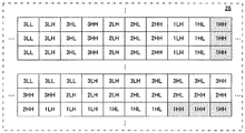
ウェーブレット変換の一例を図5に示す。図5を参照して、例えば、サブバンド分解を行う回数すなわち分解レベル数が3の場合、まず原画像(0LL)が4つのサブバンド(1LL,1HL,1LHおよび1HH)に分解され、次に1LLサブバンドが4つのサブバンド(2LL,2HL,2LHおよび2HH)に分解され、さらに2LLサブバンドが4つのサブバンド(3LL,3HL,3LHおよび3HH)に分解される。つまり、原画像は、3LL,3HL,3LH,3HH,2HL,2LH,2HH,1HL,1LHおよび1HHの10個のサブバンドに分解されることになる。 An example of the wavelet transform is shown in FIG. Referring to FIG. 5, for example, when the number of subband decompositions, that is, the number of decomposition levels is 3, the original image (0LL) is first decomposed into four subbands (1LL, 1HL, 1LH, and 1HH), and then The 1LL subband is decomposed into four subbands (2LL, 2HL, 2LH and 2HH), and the 2LL subband is further decomposed into four subbands (3LL, 3HL, 3LH and 3HH). That is, the original image is decomposed into 10 subbands of 3LL, 3HL, 3LH, 3HH, 2HL, 2LH, 2HH, 1HL, 1LH and 1HH.
次に、JPEG2000コーデック30は、ウェーブレット変換により得られたサブバンドの各々を量子化する。そして、量子化されたサブバンドの各々に対してエントロピー符号化を行う。エントロピー符号化では、量子化されたサブバンドの各々が、再生画像におけるSNR向上への寄与の度合いに応じて所定数のレイヤに分割される。この実施例でのレイヤ数は3である。
Next, the
SNR向上への寄与度が最も高いレイヤから降順にレイヤ1,レイヤ2,…と呼ぶ。最上位のレイヤ1に属するデータによって最低限のSNRを有する画像が再生され、これに下位レイヤのデータを順次追加することによって、画像のSNRが段階的に向上していく。
These are called
こうして、レイヤ1に属する10個のサブバンド3LL〜1HHと、レイヤ2に属する10個のサブバンド3LL〜1HHと、レイヤ3に属する10個のサブバンド3LL〜1HHとの合計30個のデータブロックが生成される。
Thus, a total of 30 data blocks including 10 subbands 3LL to 1HH belonging to
次に、JPEG2000コーデック30は、上記のようにして生成された30個のデータブロックを所定の順序に並べ、さらにヘッダ等の付加情報を添付することによってストリームを形成する。
Next, the
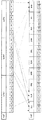
JPEG2000コーデック30によって形成されるストリームのデータ構造を図6に示す。図6(A)に示されているのはLRCP配列ストリーム、図6(B)に示されているのはRLCP配列ストリームである。Lはレイヤ、Rは解像度、Pは位置、Cは色成分を意味する。位置および色成分は省略されている。
A data structure of a stream formed by the
図6(A)を参照して、LRCP配列ストリームでは、ヘッダに続く先頭部分に、レイヤ1に属する10個のサブバンド3LL〜1HHがこの順番で配置される。これに続いてレイヤ2に属する10個のサブバンド3LL〜1HH、さらに続いてレイヤ3に属する10個のサブバンド3LL〜1HHが配置される。
Referring to FIG. 6A, in the LRCP array stream, 10 subbands 3LL to 1HH belonging to
図6(B)を参照して、RLCP配列ストリームでは、ヘッダに続く先頭部分に、サブバンド3LLを構成する3つのレイヤ1〜3がこの順番で配置される。これに続いて、サブバンド3LHを構成する3つのレイヤ1〜レイヤ3が配置され、以降、サブバンド3HLから最後のサブバンド1HHまで同様の配置が繰り返される。
Referring to FIG. 6B, in the RLCP arrangement stream, three
なお、JPEG2000ストリームを復号化する際には、JPEG2000コーデック30は、上記の符号化とは逆の処理を行う。
Note that when decoding a JPEG2000 stream, the
以下、上記のブロック並べ替え処理について詳細に説明する。本発明のブロック並べ替えによるLRCP配列ストリームからRLCP配列ストリームへの変換が図7に示されている。図7を参照して、最初、LRCP配列ストリームを構成するレイヤ1〜レイヤ3の各々から3LLのブロックが取り出される。取り出された3個のブロックは一纏めにされ、ヘッダの直後に配置される。
Hereinafter, the block rearrangement process will be described in detail. The conversion from the LRCP array stream to the RLCP array stream by the block rearrangement of the present invention is shown in FIG. Referring to FIG. 7, first, a 3LL block is extracted from each of
次に、レイヤ1〜レイヤ3の各々から3LHのブロックが取り出される。取り出された3個のブロックは一纏めにされ、3LLのブロック群の直後に配置される。以降、3HL〜1HHについて同様に、3個ブロックを一纏めにして順番に配置する処理が行われる。こうしてRLCP配列ストリームが形成される。
Next, a 3LH block is extracted from each of
本発明のブロック並べ替えによるRLCP配列ストリームからLRCP配列ストリームへの変換が図8に示されている。図8を参照して、最初、RLCP配列ストリームを構成する10個のサブバンド3LL〜1HHの各々からレイヤ1のブロックが取り出される。取り出された10個のブロックは一纏めにされ、ヘッダの直後に配置される。
The conversion from the RLCP array stream to the LRCP array stream by the block rearrangement of the present invention is shown in FIG. Referring to FIG. 8, first, a
次に、サブバンド3LL〜1HHの各々からレイヤ2のブロックが取り出される。取り出された10個のブロックは一纏めにされ、レイヤ1のブロック群の直後に配置される。次に、サブバンド3LL〜1HHの各々からレイヤ2のブロックが取り出される。取り出された10個のブロックは一纏めにされ、レイヤ2のブロック群の直後に配置される。こうしてLRCP配列ストリームが形成される。
Next, the
並べ替え制御回路341は、具体的には、以下のような手順で上記のブロック並べ替えを実行する。CPU38から並べ替え実行の指示があると、最初、並べ替え設定値レジスタ343(図2参照)に対象ブロック数343a,コピー元アドレス343b,コピー元サイズ343cおよびコピー先アドレス343dの値を順次設定する。次に、メモリ制御回路28にデータ読み出しを依頼する。
Specifically, the
応じてメモリ制御回路28は、並べ替え設定値レジスタ343に設定されている対象ブロック数343a,コピー元アドレス343bおよびコピー元サイズ343cを参照して、SDRAM26から対象ブロックのデータを読み出す。次に、読み出したデータを並べ替え回路34内のデータバッファ342に転送する。
In response, the
並べ替え制御回路341は、対象ブロックのデータがデータバッファ342に記憶されたのを受け、並べ替えるべきブロックが他にもあるか否かを判定する。この判定結果が肯定的であれば、再び並べ替え設定値レジスタ343に値を設定し、メモリ制御回路28に読み出しを依頼する。
The
上記の判定結果が否定的となる、つまり並べ替え対象である全てのブロックのデータがデータバッファ342内に記憶されると、並べ替え制御回路341は、メモリ制御回路28にデータ書き込みを依頼する。応じてメモリ制御回路28は、並べ替え設定値レジスタ343に設定されているコピー先アドレス343dを参照して、SDRAM26に全ての対象ブロックのデータを一纏めにして書き込む。
When the determination result is negative, that is, when data of all the blocks to be rearranged is stored in the
LRCP配列からRLCP配列への並べ替えを行うときのSDRAM26のマッピング状態が図9および図10に示されている。図9を参照して、当初、SDRAM26には、図6(A)のような構造を持つLRCP配列ストリームだけが記憶されている。図9に示す3本の実線矢印は、並べ替え設定値レジスタ343に設定されている3つのコピー元アドレス343bを指す。点線矢印は、コピー先アドレス343cを指す。
The mapping state of the
並べ替え処理では、最初、3つの実線矢印の示す場所にばらばらに記憶されている3個の3LLのブロックが、1つの点線矢印の示す場所に纏めてコピーされる。次に、3個の3LHのブロックが上記3個の3LLの直後の位置に纏めてコピーされる。以降、同様にして3ブロックを1箇所に纏めて順番にコピーしていく。その結果、図10に示されるように、SDRAM26には、LRCP配列ストリームに加え、図6(B)のような構造を持つRLCP配列ストリームがさらに記憶されることとなる。
In the rearrangement process, three 3LL blocks that are separately stored at locations indicated by three solid arrows are collectively copied to locations indicated by one dotted arrow. Next, three 3LH blocks are copied together at the position immediately after the three 3LLs. Thereafter, similarly, the three blocks are collected in one place and copied in order. As a result, as shown in FIG. 10, the
RLCP配列からLRCP配列への並べ替えを行うときのSDRAM26のマッピング状態が図11および図12に示されている。図11を参照して、当初、SDRAM26には、図6(B)のような構造を持つRLCP配列ストリームだけが記憶されている。3本の実線矢印は、並べ替え設定値レジスタ343に設定されている3つのコピー元アドレス343bを指す。点線矢印は、コピー先アドレス343cを指す。
The mapping state of the
並べ替え処理では、最初、3つの実線矢印の示す場所にばらばらに記憶されている3LL,3LHおよび3HLの3ブロックが、1つの点線矢印の示す場所に纏めてコピーされる。次に、3HH,2LHおよび2HLが上記3ブロックの直後の位置に纏めてコピーされる。以降、同様にして3ブロックを1箇所に纏めて順番にコピーしていく。その結果、図12に示されるように、SDRAM26には、RLCP配列ストリームに加え、図6(A)のような構造を持つLRCP配列ストリームがさらに記憶されることとなる。
In the rearrangement process, three blocks of 3LL, 3LH, and 3HL that are separately stored at the locations indicated by the three solid arrows are collectively copied to the location indicated by the single dotted arrow. Next, 3HH, 2LH and 2HL are copied together at the position immediately after the three blocks. Thereafter, similarly, the three blocks are collected in one place and copied in order. As a result, as shown in FIG. 12, the
以上のように構成された監視カメラシステム10の全体動作を、図13および図14に示されたCPU38の処理フローに基づき以下に説明する。
The overall operation of the
この監視カメラシステム10は、例えばオフィスビルや集合住宅などで用いられる。カメラ12は、例えば玄関や通路に設置され、サーバ16およびモニタ14は、例えば管理室に設けられる。なお、カメラ12は1台とは限らない。複数のカメラ12を設置する場合、各カメラ12,12,…は、図示しないマルチプレクサを介してD−I/F22に接続される。
This
サーバ16は、必要に応じ、イントラネットやインターネットを介してビルの内外にある端末T1,T2,…と接続される。従って、ユーザは、管理室内のモニタ16だけでなく、外部の端末T1,T2,…からも監視画像を閲覧することができる。
The
CPU38は、具体的には、フラッシュメモリ36のプログラム361に従い、図13および図14のフロー図を処理する。図13を参照して、サーバ16が起動されると、ステップS1でCPU38は、初期処理を行う。初期処理には、例えばメモリ制御回路28にSDRAM26の初期化を指示したり、ネットワークI/F40にネットワークとの接続確立を命じたり、JPEG2000コーデック30に初期パラメータを設定したりする処理などが含まれる。
Specifically, the
その後、カメラ12が起動され、カメラ12から出力された画像信号がD−I/F22を通じてサーバ16内に取り込まれる。ステップS3でCPU38は、カメラ12からの画像信号がD−I/F22に入力された否かを判定する。この判定結果が肯定的であればステップS5に、否定的であればステップS7に進む。
Thereafter, the
ステップS5でCPU38は、メモリ制御回路28およびJPEG2000コーデック30に対し、符号化処理の実行を指示する。この指示では、LRCP配列およびRLCP配列の一方が指定される。応じて、メモリ制御回路28およびJPEG2000コーデック30は、以下のような処理を行う。
In step S5, the
メモリ制御回路28は、取り込まれた画像信号をいったんSDRAM26に書き込み、その後、この画像信号をSDRAM26から読み出して、JPEG2000コーデック30に入力する。なお、このとき読み出された画像信号は、ビデオ出力回路24にも与えられ、モニタ14にライブ画像が表示される。
The
JPEG2000コーデック30は、入力された画像信号を、LRCP配列およびRLCP配列のうちCPU38により指定された方のストリームに符号化する。JPEG2000コーデック30から出力されたストリームは、メモリ制御回路28によって再びSDRAM26に書き込まれる。
The
ステップS7でCPU38は、メモリ制御回路28およびIDE−I/F20を通じ、SDRAM26に一時記憶されているストリームをHD18aに書き出す。
In step S7, the
ところで、端末T1,T2,…は、画像を閲覧する際の画質を予めサーバ16に申告しており、サーバ16のフラッシュメモリ36には、端末T1,T2,…の各々が申告した画質を記載した再生用テーブル363(図4参照)が格納されている。
By the way, the terminals T1, T2,... Declare the image quality when browsing the image to the
端末T1,T2,…は、カメラ12によって撮影された画像を閲覧したい場合、サーバ16に要求信号を送信する。要求信号には、端末自身の識別子と、画像の識別子すなわち例えばカメラ12の番号および撮影日時とが添付される。
The terminals T1, T2,... Transmit a request signal to the
ステップS9でCPU38は、端末T1,T2,…からネットワークI/F40へ要求信号が送られてきたか否かを判定する。この判定結果が肯定的であればステップS11に、否定的であればステップS13に進む。
In step S9, the
ステップS11でCPU38は、ネットワークI/F40が受信した要求信号の内容を解析し、この解析結果に基づいて、送信元の端末を特定する。ステップS13では、IDE−I/F20,メモリ制御回路28,JPEG2000コーデック30,並べ替え制御回路341およびネットワークI/F40に対し、特定端末への画像送信の実行を指示する。その後、ステップS15に進む。
In step S11, the
ステップS15でCPU38は、処理を継続するか否かを判断する。継続する場合はステップS3に戻り、上記と同様の処理を繰り返す。
In step S15, the
上記ステップS13の画像送信指示は、図14のサブルーチンに従って実行される。図14を参照して、ステップS51でCPU38は、ステップS11で特定された端末が解像度を指定しているか否かを再生用テーブル363(図4参照)に基づいて判定する。この判定結果が肯定的であればステップS53に進み、否定的であればステップS63に進む。
The image transmission instruction in step S13 is executed according to the subroutine of FIG. Referring to FIG. 14, in step S51,
ステップS53では、SDRAM26もしくはHD18a内に指定画像のRLCP配列ストリームが記憶されているか否かを判定する。この判定結果が否定的であればステップS55に、肯定的であればステップS59に進む。
In step S53, it is determined whether the RLCP array stream of the designated image is stored in the
ステップS55でCPU38は、再生用テーブル363に基づいて、並べ替えの対象となるブロック数を計算する。例えば、端末T1からの閲覧要求に対しては、再生用テーブル363に“高解像度”が登録されていることから、図6(B)のように構成されたRLCP配列ストリームの全てのサブバンド(3LL〜1HH)を送信しなければならない。1サブバンド当たりのブロック数は3個なので、並べ替えブロック数は、3×10=30個のように計算される。もし“中解像度”が登録されていればサブバンド3LL〜2HHを送信しなければならないので、並べ替えブロック数は3×7=21となる。同様に、“低解像度”が登録されていればサブバンド3LL〜3HHを送信すればよいので、並べ替えブロック数は3×4=12となる。
In step S55, the
ステップS57でCPU38は、メモリ制御回路28およびブロック並べ替え回路34に対し、ブロック並べ替え処理の実行を指示する。実行指示では、並べ替えの対象となるブロック数が指定される。その後、ステップS59に進む。
In step S57, the
応じて、メモリ制御回路28およびブロック並べ替え回路34は、以下のような並べ替え処理を実行する。最初、並べ替え制御回路341が、並べ替え設定値レジスタ343(図2参照)にパラメータの値を設定する。具体的には、まず対象ブロック数343aに、CPU38により指定された対象ブロック数(図2では“3”)をセットし、次いでコピー元アドレス343bおよびコピー元サイズの各々に対象ブロック数343aと同数(図2では3個)の値をセットし、さらにコピー先アドレス343dに1個の値をセットする。
In response, the
メモリ制御回路28は、並べ替え設定値レジスタ343の設定内容を参照して、指定されたコピー元アドレス343bから対象ブロック数343aと同数のブロックを読み出し、読み出したブロックを一纏めにしてコピー先アドレス343dに書き込む。
The
ステップS59でCPU38は、メモリ制御回路28もしくはIDE−I/F20に対し、RLCP配列ストリームの読み出しを指示する。ステップS61では、ネットワークI/F40に対し、読み出されたRLCP配列ストリームの送信を指示する。具体的には、再生用テーブル363の該当欄に“解像度”の値が登録されている端末に向けて、登録解像度のRLCP配列ストリームを送信するように、ネットワークI/F40に指示を出す。その後、ステップS63に進む。
In step S59, the
この実施例では、端末T1欄363aに“高解像度”が登録されていることから、端末T1宛にRLCP配列ストリームの全解像度レベル(サブバンド3LL〜1HH)が送信されることとなる。もし“中解像度”が登録されていれば解像度レベル1および2(サブバンド3LL〜2HH)が、“低解像度”が登録されていれば解像度レベル1(サブバンド3LL〜3HH)が送信される。
In this embodiment, since “high resolution” is registered in the
ステップS63でCPU38は、閲覧要求においてSNRが指定されているか否かを判定する。この判定結果が肯定的であればステップS65に進み、否定的であれば上位階層のルーチンに復帰する。ステップS65では、SDRAM26もしくはHD18a内に指定画像のLRCP配列ストリームが記憶されているか否かを判定する。この判定結果が否定的であればステップS67に、肯定的であればステップS71に進む。
In step S63, the
ステップS67でCPU38は、再生用テーブル363に基づいて、並べ替えの対象となるブロック数を計算する。例えば、端末T2からの閲覧要求に対しては、再生用テーブル363に“低SNR”が登録されていることから、図6(A)のように構成されたLRCP配列ストリームの最上位レイヤ(レイヤ1に属する3LL〜3HH)だけを送信すればよい。よって、並べ替えブロック数は、10×1=10個のように計算される。もし“中SNR”が登録されていればレイヤ1およびレイヤ2を送信しなければならないので、並べ替えブロック数は、10×2=20となる。同様に、“高SNR”が登録されていればレイヤ1〜3を送信しなければならないので、並べ替えブロック数は、10×3=30となる。
In step S67, the
ステップS69でCPU38は、メモリ制御回路28およびブロック並べ替え回路34に対し、ブロック並べ替え処理の実行を指示する。その後、ステップS71に進む。なお、ステップS69のブロック並べ替え処理は、上記ステップS57のそれと同様のものである。
In step S69, the
ステップS71でCPU38は、メモリ制御回路28もしくはIDE−I/F20に対し、LRCP配列ストリームの読み出しを指示する。ステップS73では、ネットワークI/F40に対し、LRCP配列ストリームの送信を指示する。具体的には、再生用テーブル363の該当欄に“SNR”の値が登録されている端末に向けて、登録SNRのLRCP配列ストリームを送信するように、ネットワークI/F40に指示を出す。その後、上位階層のルーチンに復帰する。
In step S71, the
この実施例では、端末T2欄363aに“低SNR”が登録されていることから、端末T2宛にLRCP配列ストリームのレイヤ1(レイヤ1に属するサブバンド3LL〜1HH)だけが送信されることとなる。もし“高SNR”が登録されていればレイヤ1〜3が、“中SNR”が登録されていればレイヤ1および2が送信される。
In this embodiment, since “low SNR” is registered in the
以上のように、この実施例では、JPEG2000コーデック30がLRCP配列およびRLCP配列のうちどちらか一方のストリームを形成し、ブロック並べ替え回路34は、形成されたストリームをデータブロック単位でコピーして再配列することにより他方のストリームに変換する。こうすれば、LRCP配列ストリームおよびRLCP配列ストリームの両方をJPEG2000コーデック30が生成する場合と比べ、処理時間が短縮されるので、快適性を損なうことなく、異なる解像度および異なるSNRの両方を含む様々な画質で画像を再生することができる。
As described above, in this embodiment, the JPEG 2000
なお、この実施例のように専用のブロック並べ替え回路34を設ける代わりに、CPU38が同様の並べ替え処理を実行してもよい。この場合、データバッファ342および並べ替え設定値レジスタ343は、例えばフラッシュメモリ36内に設けられる。プログラム記憶領域361には、並べ替え処理を記述したプログラムがさらに格納され、CPU38は、このプログラムに従い、並べ替え制御回路341と同様の動作を行う。
Instead of providing the dedicated
また、この実施例のようにストリーム送信時に並べ替えを行う代わりに、LRCP配列およびRLCP配列の両方のストリームをHD18aに記録してもよい。この方法は、HD18aが十分な容量を有する場合に有効である。この場合のCPU38の処理例を以下に示す。
Further, instead of rearranging at the time of stream transmission as in this embodiment, both streams of the LRCP arrangement and the RLCP arrangement may be recorded on the
CPU38は、HD18aの空き容量が閾値以上か否かを判定する。この判定結果が肯定的であれば、CPU38は、LRCP配列ストリームおよびRLCP配列ストリームをHD18aに記録する。
The
上記の判定結果が肯定的、すなわちHD18aの空き容量が閾値未満であれば、CPU38は、録画用テーブル362a(図3)を参照して、スケーラビリティ362dの設定値が“解像度優先”であるか否かを判定する。この判定結果が肯定的であれば、CPU38は、RLCP配列ストリームをHD18aに記録し、否定的すなわち“SNR優先”であればLRCP配列ストリームをHD18aに記録する。
If the above determination result is affirmative, that is, if the free space of the
画像送信時には、指定された配列のストリームをHD18aから読み出して送信する。HD18aに一方の配列のストリームしか記録されていない画像については、図14に示されているものと同様の送信制御を行えばよい。
At the time of image transmission, the stream of the designated arrangement is read from the
10…監視カメラシステム
12…カメラ
14…モニタ
16…サーバ
18a…HD(ハードディスク)
26…SDRAM
30…JPEG2000コーデック
34…ブロック並べ替え回路
36…フラッシュメモリ
38…CPU
DESCRIPTION OF
26 ... SDRAM
30 ...
Claims (4)
前記符号化手段によって符号化された第1データブロック列を記録媒体に記録する記録手段、
データブロック列の送信要求を受け付ける受け付け手段、
前記受け付け手段によって受け付けられた送信要求が前記第1データブロック列および前記複数の画質パラメータの他の1つを最優先とする第2態様で配列された複数のデータブロックを含む第2データブロック列のいずれを要求しているかを判別する第1判別手段、
前記受け付け手段によって受け付けられた送信要求がいくつのデータブロックを要求しているかを判別する第2判別手段、
前記第1判別手段の判別結果が前記第2データブロック列を示すとき、前記記録手段によって記録媒体に記録された第1データブロック列から前記第2態様に従う順序で前記第2判別手段の判別結果に応じた数のデータブロックを抽出し、そして抽出されたデータブロックを先頭から順にメモリに配列する並び替え手段、および
前記第1判別手段の判別結果が前記第2データブロック列を示すとき、前記並び替え手段によって前記メモリに配列されたデータブロック列を送信する送信手段を備える、データ処理装置。 It includes a plurality of data blocks arranged in a first manner in which input data that is still image data is hierarchically encoded based on a plurality of image quality parameters including resolution and SNR, and one of the plurality of image quality parameters is given the highest priority. Encoding means for generating a first data block sequence;
Recording means for recording the first data block sequence encoded by the encoding means on a recording medium;
Receiving means for receiving a transmission request for a data block sequence;
A second data block sequence including a plurality of data blocks arranged in a second manner in which the transmission request received by the receiving means has the first data block sequence and the other one of the plurality of image quality parameters as the highest priority. A first discriminating means for discriminating which one is requested,
Second determination means for determining how many data blocks the transmission request received by the reception means requires;
When the determination result of the first determination unit indicates the second data block sequence, the determination result of the second determination unit in the order according to the second mode from the first data block sequence recorded on the recording medium by the recording unit A number of data blocks corresponding to the number , and rearrangement means for arranging the extracted data blocks in the memory in order from the top , and when the determination result of the first determination means indicates the second data block sequence, A data processing apparatus comprising: a transmission unit that transmits a data block sequence arranged in the memory by a rearrangement unit .
優先すべき画質パラメータおよび当該画質パラメータの高低を端末毎に記述したテーブルをさらに備え、
前記第1判別手段および前記第2判別手段の各々は前記テーブルに基づいて判別を行う、請求項1記載のデータ処理装置。 The transmission request is issued by each of a plurality of terminals,
It further comprises a table describing the image quality parameter to be prioritized and the level of the image quality parameter for each terminal,
The data processing apparatus according to claim 1, wherein each of the first determination unit and the second determination unit performs determination based on the table .
Priority Applications (4)
| Application Number | Priority Date | Filing Date | Title |
|---|---|---|---|
| JP2003345852A JP4097586B2 (en) | 2003-10-03 | 2003-10-03 | Data processing device |
| CNA200410080632XA CN1604636A (en) | 2003-10-03 | 2004-09-29 | Data processing apparatus |
| EP20040023339 EP1521474A3 (en) | 2003-10-03 | 2004-09-30 | Data processing apparatus |
| US10/954,770 US20050073892A1 (en) | 2003-10-03 | 2004-10-01 | Data processing apparatus |
Applications Claiming Priority (1)
| Application Number | Priority Date | Filing Date | Title |
|---|---|---|---|
| JP2003345852A JP4097586B2 (en) | 2003-10-03 | 2003-10-03 | Data processing device |
Publications (2)
| Publication Number | Publication Date |
|---|---|
| JP2005117156A JP2005117156A (en) | 2005-04-28 |
| JP4097586B2 true JP4097586B2 (en) | 2008-06-11 |
Family
ID=34309163
Family Applications (1)
| Application Number | Title | Priority Date | Filing Date |
|---|---|---|---|
| JP2003345852A Expired - Lifetime JP4097586B2 (en) | 2003-10-03 | 2003-10-03 | Data processing device |
Country Status (4)
| Country | Link |
|---|---|
| US (1) | US20050073892A1 (en) |
| EP (1) | EP1521474A3 (en) |
| JP (1) | JP4097586B2 (en) |
| CN (1) | CN1604636A (en) |
Families Citing this family (7)
| Publication number | Priority date | Publication date | Assignee | Title |
|---|---|---|---|---|
| TW200727598A (en) * | 2005-11-18 | 2007-07-16 | Sony Corp | Encoding/decoding device/method and the transmission system |
| CN101129063B (en) * | 2005-11-18 | 2010-05-19 | 索尼株式会社 | Encoding device and method, decoding device and method, and transmission system |
| JP4789192B2 (en) * | 2006-04-12 | 2011-10-12 | 株式会社リコー | Code processing apparatus, program, and information recording medium |
| JP4254867B2 (en) * | 2007-01-31 | 2009-04-15 | ソニー株式会社 | Information processing apparatus and method, program, and recording medium |
| CN102037514A (en) * | 2008-05-21 | 2011-04-27 | Nxp股份有限公司 | A data handling system comprising a rearrangement network |
| US20120265768A1 (en) * | 2008-10-08 | 2012-10-18 | Mitsubishi Electric Corporation | Encoding and decoding method and apparatus for multimedia signatures |
| JP5263621B2 (en) * | 2009-09-24 | 2013-08-14 | ソニー株式会社 | Image processing apparatus and method |
Family Cites Families (1)
| Publication number | Priority date | Publication date | Assignee | Title |
|---|---|---|---|---|
| US6898323B2 (en) * | 2001-02-15 | 2005-05-24 | Ricoh Company, Ltd. | Memory usage scheme for performing wavelet processing |
-
2003
- 2003-10-03 JP JP2003345852A patent/JP4097586B2/en not_active Expired - Lifetime
-
2004
- 2004-09-29 CN CNA200410080632XA patent/CN1604636A/en active Pending
- 2004-09-30 EP EP20040023339 patent/EP1521474A3/en not_active Withdrawn
- 2004-10-01 US US10/954,770 patent/US20050073892A1/en not_active Abandoned
Also Published As
| Publication number | Publication date |
|---|---|
| EP1521474A3 (en) | 2006-03-22 |
| US20050073892A1 (en) | 2005-04-07 |
| EP1521474A2 (en) | 2005-04-06 |
| CN1604636A (en) | 2005-04-06 |
| JP2005117156A (en) | 2005-04-28 |
Similar Documents
| Publication | Publication Date | Title |
|---|---|---|
| JP5684920B2 (en) | Various bit video streams for adaptive streaming | |
| US8270469B2 (en) | Encoding video at multiple resolution levels | |
| JP2008543162A (en) | Method of transmitting image information at the time of encoding video signal, and method of using image information at the time of decoding video signal | |
| US20060015634A1 (en) | Progressive streaming media rendering | |
| US7260614B2 (en) | Methods and systems for scalable streaming of images with client-side control | |
| JP2005512470A (en) | Method and apparatus for dynamically allocating scalable selective extensions to FGS encoded images | |
| CN101540867B (en) | Imaging apparatus | |
| JP2007142614A (en) | Image processing apparatus and method, program, and information recording medium | |
| JP4097586B2 (en) | Data processing device | |
| JP2006279850A (en) | Image processing apparatus | |
| US20030223733A1 (en) | System and method of processing audio/video data in a remote monitoring system | |
| CN103947193A (en) | Imaging device, video recording device, video display device, video monitoring device, video monitoring system, and video monitoring method | |
| JP4915208B2 (en) | Stream data playback system | |
| JP2011147051A (en) | Image processing apparatus and method | |
| JP2006157452A (en) | Image compressing device and method | |
| US8571379B2 (en) | Video reproduction method, video reproduction device, and video distribution system | |
| WO2013154024A1 (en) | Information processing device and method, and program | |
| JP2014137674A (en) | Information processing apparatus, method and program | |
| JP2022031267A (en) | Streaming system and encoding program | |
| JP2007006194A (en) | Image decoding/reproducing apparatus | |
| JP2006139682A (en) | Video search system, video search method, and program | |
| JP2014075688A (en) | Image processor and image processing method | |
| US20050207344A1 (en) | Data transfer apparatus and image server | |
| KR102372421B1 (en) | Multimedia data live streaming system and method in response to network condition | |
| KR100466790B1 (en) | integerated DVR system |
Legal Events
| Date | Code | Title | Description |
|---|---|---|---|
| A621 | Written request for application examination |
Free format text: JAPANESE INTERMEDIATE CODE: A621 Effective date: 20060928 |
|
| A131 | Notification of reasons for refusal |
Free format text: JAPANESE INTERMEDIATE CODE: A131 Effective date: 20071120 |
|
| A521 | Written amendment |
Free format text: JAPANESE INTERMEDIATE CODE: A523 Effective date: 20080116 |
|
| TRDD | Decision of grant or rejection written | ||
| A01 | Written decision to grant a patent or to grant a registration (utility model) |
Free format text: JAPANESE INTERMEDIATE CODE: A01 Effective date: 20080212 |
|
| A61 | First payment of annual fees (during grant procedure) |
Free format text: JAPANESE INTERMEDIATE CODE: A61 Effective date: 20080311 |
|
| FPAY | Renewal fee payment (event date is renewal date of database) |
Free format text: PAYMENT UNTIL: 20110321 Year of fee payment: 3 |
|
| FPAY | Renewal fee payment (event date is renewal date of database) |
Free format text: PAYMENT UNTIL: 20110321 Year of fee payment: 3 |
|
| FPAY | Renewal fee payment (event date is renewal date of database) |
Free format text: PAYMENT UNTIL: 20130321 Year of fee payment: 5 |