JP4096718B2 - Bipolar battery, bipolar battery manufacturing method, battery pack and vehicle - Google Patents
Bipolar battery, bipolar battery manufacturing method, battery pack and vehicle Download PDFInfo
- Publication number
- JP4096718B2 JP4096718B2 JP2002345745A JP2002345745A JP4096718B2 JP 4096718 B2 JP4096718 B2 JP 4096718B2 JP 2002345745 A JP2002345745 A JP 2002345745A JP 2002345745 A JP2002345745 A JP 2002345745A JP 4096718 B2 JP4096718 B2 JP 4096718B2
- Authority
- JP
- Japan
- Prior art keywords
- battery
- active material
- electrode active
- bipolar battery
- layer
- Prior art date
- Legal status (The legal status is an assumption and is not a legal conclusion. Google has not performed a legal analysis and makes no representation as to the accuracy of the status listed.)
- Expired - Lifetime
Links
- 238000004519 manufacturing process Methods 0.000 title claims description 23
- 239000004820 Pressure-sensitive adhesive Substances 0.000 claims description 55
- 239000011245 gel electrolyte Substances 0.000 claims description 46
- 239000007774 positive electrode material Substances 0.000 claims description 37
- 239000000463 material Substances 0.000 claims description 29
- 239000007773 negative electrode material Substances 0.000 claims description 29
- 239000000853 adhesive Substances 0.000 claims description 20
- 230000001070 adhesive effect Effects 0.000 claims description 20
- -1 polypropylene Polymers 0.000 claims description 15
- OKTJSMMVPCPJKN-UHFFFAOYSA-N Carbon Chemical compound [C] OKTJSMMVPCPJKN-UHFFFAOYSA-N 0.000 claims description 8
- 239000004743 Polypropylene Substances 0.000 claims description 8
- 239000002131 composite material Substances 0.000 claims description 8
- 238000010030 laminating Methods 0.000 claims description 8
- 229920001155 polypropylene Polymers 0.000 claims description 8
- 239000011810 insulating material Substances 0.000 claims description 7
- 238000000034 method Methods 0.000 claims description 7
- 229910052744 lithium Inorganic materials 0.000 claims description 6
- 239000002904 solvent Substances 0.000 claims description 6
- WHXSMMKQMYFTQS-UHFFFAOYSA-N Lithium Chemical compound [Li] WHXSMMKQMYFTQS-UHFFFAOYSA-N 0.000 claims description 4
- 229910052799 carbon Inorganic materials 0.000 claims description 4
- 229920005989 resin Polymers 0.000 claims description 4
- 239000011347 resin Substances 0.000 claims description 4
- 229910052723 transition metal Inorganic materials 0.000 claims description 4
- 150000003624 transition metals Chemical class 0.000 claims description 4
- 239000004698 Polyethylene Substances 0.000 claims description 3
- 229920000573 polyethylene Polymers 0.000 claims description 3
- 229920003051 synthetic elastomer Polymers 0.000 claims description 3
- 239000005061 synthetic rubber Substances 0.000 claims description 3
- 239000004952 Polyamide Substances 0.000 claims description 2
- NIXOWILDQLNWCW-UHFFFAOYSA-N acrylic acid group Chemical group C(C=C)(=O)O NIXOWILDQLNWCW-UHFFFAOYSA-N 0.000 claims description 2
- 229920005549 butyl rubber Polymers 0.000 claims description 2
- 229920002647 polyamide Polymers 0.000 claims description 2
- 229920002994 synthetic fiber Polymers 0.000 claims description 2
- 239000012209 synthetic fiber Substances 0.000 claims description 2
- 229920003002 synthetic resin Polymers 0.000 claims description 2
- 239000000057 synthetic resin Substances 0.000 claims description 2
- 239000003792 electrolyte Substances 0.000 description 29
- 229920000642 polymer Polymers 0.000 description 26
- 239000007788 liquid Substances 0.000 description 17
- 239000005518 polymer electrolyte Substances 0.000 description 15
- 239000008151 electrolyte solution Substances 0.000 description 14
- HBBGRARXTFLTSG-UHFFFAOYSA-N Lithium ion Chemical compound [Li+] HBBGRARXTFLTSG-UHFFFAOYSA-N 0.000 description 13
- 229910001416 lithium ion Inorganic materials 0.000 description 13
- 239000007787 solid Substances 0.000 description 12
- SECXISVLQFMRJM-UHFFFAOYSA-N N-Methylpyrrolidone Chemical compound CN1CCCC1=O SECXISVLQFMRJM-UHFFFAOYSA-N 0.000 description 10
- 238000011156 evaluation Methods 0.000 description 10
- 230000000052 comparative effect Effects 0.000 description 9
- PXHVJJICTQNCMI-UHFFFAOYSA-N Nickel Chemical compound [Ni] PXHVJJICTQNCMI-UHFFFAOYSA-N 0.000 description 7
- 239000002033 PVDF binder Substances 0.000 description 7
- 229910052782 aluminium Inorganic materials 0.000 description 7
- XAGFODPZIPBFFR-UHFFFAOYSA-N aluminium Chemical compound [Al] XAGFODPZIPBFFR-UHFFFAOYSA-N 0.000 description 7
- 229910052751 metal Inorganic materials 0.000 description 7
- 239000002184 metal Substances 0.000 description 7
- 229920002981 polyvinylidene fluoride Polymers 0.000 description 7
- 239000011230 binding agent Substances 0.000 description 6
- 150000002500 ions Chemical class 0.000 description 6
- 238000002156 mixing Methods 0.000 description 6
- 239000010935 stainless steel Substances 0.000 description 6
- 229910001220 stainless steel Inorganic materials 0.000 description 6
- 229910003002 lithium salt Inorganic materials 0.000 description 5
- 159000000002 lithium salts Chemical class 0.000 description 5
- OZAIFHULBGXAKX-UHFFFAOYSA-N 2-(2-cyanopropan-2-yldiazenyl)-2-methylpropanenitrile Chemical compound N#CC(C)(C)N=NC(C)(C)C#N OZAIFHULBGXAKX-UHFFFAOYSA-N 0.000 description 4
- KMTRUDSVKNLOMY-UHFFFAOYSA-N Ethylene carbonate Chemical compound O=C1OCCO1 KMTRUDSVKNLOMY-UHFFFAOYSA-N 0.000 description 4
- 230000008859 change Effects 0.000 description 4
- 238000010586 diagram Methods 0.000 description 4
- 238000007599 discharging Methods 0.000 description 4
- 239000002905 metal composite material Substances 0.000 description 4
- 239000002245 particle Substances 0.000 description 4
- 239000000843 powder Substances 0.000 description 4
- 150000003839 salts Chemical class 0.000 description 4
- WEVYAHXRMPXWCK-UHFFFAOYSA-N Acetonitrile Chemical compound CC#N WEVYAHXRMPXWCK-UHFFFAOYSA-N 0.000 description 3
- RYGMFSIKBFXOCR-UHFFFAOYSA-N Copper Chemical compound [Cu] RYGMFSIKBFXOCR-UHFFFAOYSA-N 0.000 description 3
- ZMXDDKWLCZADIW-UHFFFAOYSA-N N,N-Dimethylformamide Chemical compound CN(C)C=O ZMXDDKWLCZADIW-UHFFFAOYSA-N 0.000 description 3
- 239000006230 acetylene black Substances 0.000 description 3
- 229910045601 alloy Inorganic materials 0.000 description 3
- 239000000956 alloy Substances 0.000 description 3
- 239000002482 conductive additive Substances 0.000 description 3
- 239000010949 copper Substances 0.000 description 3
- 229910052802 copper Inorganic materials 0.000 description 3
- IEJIGPNLZYLLBP-UHFFFAOYSA-N dimethyl carbonate Chemical compound COC(=O)OC IEJIGPNLZYLLBP-UHFFFAOYSA-N 0.000 description 3
- 239000011888 foil Substances 0.000 description 3
- 229910052759 nickel Inorganic materials 0.000 description 3
- 229920003229 poly(methyl methacrylate) Polymers 0.000 description 3
- 229920002239 polyacrylonitrile Polymers 0.000 description 3
- 239000004926 polymethyl methacrylate Substances 0.000 description 3
- 238000005507 spraying Methods 0.000 description 3
- 239000000758 substrate Substances 0.000 description 3
- 239000010936 titanium Substances 0.000 description 3
- 238000003466 welding Methods 0.000 description 3
- YEJRWHAVMIAJKC-UHFFFAOYSA-N 4-Butyrolactone Chemical compound O=C1CCCO1 YEJRWHAVMIAJKC-UHFFFAOYSA-N 0.000 description 2
- 229910010238 LiAlCl 4 Inorganic materials 0.000 description 2
- 229910015015 LiAsF 6 Inorganic materials 0.000 description 2
- 229910013063 LiBF 4 Inorganic materials 0.000 description 2
- 229910013684 LiClO 4 Inorganic materials 0.000 description 2
- 229910015643 LiMn 2 O 4 Inorganic materials 0.000 description 2
- 229910013870 LiPF 6 Inorganic materials 0.000 description 2
- 229920003171 Poly (ethylene oxide) Polymers 0.000 description 2
- WYURNTSHIVDZCO-UHFFFAOYSA-N Tetrahydrofuran Chemical compound C1CCOC1 WYURNTSHIVDZCO-UHFFFAOYSA-N 0.000 description 2
- RTAQQCXQSZGOHL-UHFFFAOYSA-N Titanium Chemical compound [Ti] RTAQQCXQSZGOHL-UHFFFAOYSA-N 0.000 description 2
- 239000011149 active material Substances 0.000 description 2
- 230000008901 benefit Effects 0.000 description 2
- 230000015556 catabolic process Effects 0.000 description 2
- 230000007423 decrease Effects 0.000 description 2
- 238000006731 degradation reaction Methods 0.000 description 2
- 230000007613 environmental effect Effects 0.000 description 2
- 239000010408 film Substances 0.000 description 2
- 239000005001 laminate film Substances 0.000 description 2
- 239000011244 liquid electrolyte Substances 0.000 description 2
- 101150004907 litaf gene Proteins 0.000 description 2
- 230000007774 longterm Effects 0.000 description 2
- TZIHFWKZFHZASV-UHFFFAOYSA-N methyl formate Chemical compound COC=O TZIHFWKZFHZASV-UHFFFAOYSA-N 0.000 description 2
- 239000004014 plasticizer Substances 0.000 description 2
- 238000002360 preparation method Methods 0.000 description 2
- 239000007784 solid electrolyte Substances 0.000 description 2
- 229910052719 titanium Inorganic materials 0.000 description 2
- 229910000314 transition metal oxide Inorganic materials 0.000 description 2
- RYHBNJHYFVUHQT-UHFFFAOYSA-N 1,4-Dioxane Chemical compound C1COCCO1 RYHBNJHYFVUHQT-UHFFFAOYSA-N 0.000 description 1
- GDXHBFHOEYVPED-UHFFFAOYSA-N 1-(2-butoxyethoxy)butane Chemical compound CCCCOCCOCCCC GDXHBFHOEYVPED-UHFFFAOYSA-N 0.000 description 1
- JWUJQDFVADABEY-UHFFFAOYSA-N 2-methyltetrahydrofuran Chemical compound CC1CCCO1 JWUJQDFVADABEY-UHFFFAOYSA-N 0.000 description 1
- BVKZGUZCCUSVTD-UHFFFAOYSA-L Carbonate Chemical compound [O-]C([O-])=O BVKZGUZCCUSVTD-UHFFFAOYSA-L 0.000 description 1
- OIFBSDVPJOWBCH-UHFFFAOYSA-N Diethyl carbonate Chemical compound CCOC(=O)OCC OIFBSDVPJOWBCH-UHFFFAOYSA-N 0.000 description 1
- 229910012851 LiCoO 2 Inorganic materials 0.000 description 1
- 229910010586 LiFeO 2 Inorganic materials 0.000 description 1
- 229910010707 LiFePO 4 Inorganic materials 0.000 description 1
- 229910013290 LiNiO 2 Inorganic materials 0.000 description 1
- RJUFJBKOKNCXHH-UHFFFAOYSA-N Methyl propionate Chemical compound CCC(=O)OC RJUFJBKOKNCXHH-UHFFFAOYSA-N 0.000 description 1
- 229910002640 NiOOH Inorganic materials 0.000 description 1
- XBDQKXXYIPTUBI-UHFFFAOYSA-M Propionate Chemical compound CCC([O-])=O XBDQKXXYIPTUBI-UHFFFAOYSA-M 0.000 description 1
- QAOWNCQODCNURD-UHFFFAOYSA-N Sulfuric acid Chemical class OS(O)(=O)=O QAOWNCQODCNURD-UHFFFAOYSA-N 0.000 description 1
- GWEVSGVZZGPLCZ-UHFFFAOYSA-N Titan oxide Chemical compound O=[Ti]=O GWEVSGVZZGPLCZ-UHFFFAOYSA-N 0.000 description 1
- KXKVLQRXCPHEJC-UHFFFAOYSA-N acetic acid trimethyl ester Natural products COC(C)=O KXKVLQRXCPHEJC-UHFFFAOYSA-N 0.000 description 1
- 150000001408 amides Chemical class 0.000 description 1
- 239000000010 aprotic solvent Substances 0.000 description 1
- 239000012752 auxiliary agent Substances 0.000 description 1
- 230000015572 biosynthetic process Effects 0.000 description 1
- 239000006229 carbon black Substances 0.000 description 1
- 150000005678 chain carbonates Chemical class 0.000 description 1
- 239000003795 chemical substances by application Substances 0.000 description 1
- 229920001940 conductive polymer Polymers 0.000 description 1
- 229920001577 copolymer Polymers 0.000 description 1
- 230000007797 corrosion Effects 0.000 description 1
- 238000005260 corrosion Methods 0.000 description 1
- 150000005676 cyclic carbonates Chemical class 0.000 description 1
- 238000009792 diffusion process Methods 0.000 description 1
- 125000000118 dimethyl group Chemical group [H]C([H])([H])* 0.000 description 1
- 230000000694 effects Effects 0.000 description 1
- 239000011267 electrode slurry Substances 0.000 description 1
- 238000005868 electrolysis reaction Methods 0.000 description 1
- 238000010894 electron beam technology Methods 0.000 description 1
- 239000003822 epoxy resin Substances 0.000 description 1
- 150000002148 esters Chemical class 0.000 description 1
- JBTWLSYIZRCDFO-UHFFFAOYSA-N ethyl methyl carbonate Chemical compound CCOC(=O)OC JBTWLSYIZRCDFO-UHFFFAOYSA-N 0.000 description 1
- XTHFKEDIFFGKHM-UHFFFAOYSA-N ethylene glycol dimethyl ether Natural products COCCOC XTHFKEDIFFGKHM-UHFFFAOYSA-N 0.000 description 1
- 239000004744 fabric Substances 0.000 description 1
- 230000004927 fusion Effects 0.000 description 1
- 239000010439 graphite Substances 0.000 description 1
- 229910002804 graphite Inorganic materials 0.000 description 1
- 239000012212 insulator Substances 0.000 description 1
- 238000005304 joining Methods 0.000 description 1
- 150000002596 lactones Chemical class 0.000 description 1
- SWAIALBIBWIKKQ-UHFFFAOYSA-N lithium titanium Chemical compound [Li].[Ti] SWAIALBIBWIKKQ-UHFFFAOYSA-N 0.000 description 1
- 229910044991 metal oxide Inorganic materials 0.000 description 1
- 150000004706 metal oxides Chemical class 0.000 description 1
- 229910052976 metal sulfide Inorganic materials 0.000 description 1
- 150000002739 metals Chemical class 0.000 description 1
- 229940017219 methyl propionate Drugs 0.000 description 1
- 239000000203 mixture Substances 0.000 description 1
- 238000000465 moulding Methods 0.000 description 1
- 150000002825 nitriles Chemical class 0.000 description 1
- 239000003960 organic solvent Substances 0.000 description 1
- 230000002093 peripheral effect Effects 0.000 description 1
- 229920000647 polyepoxide Polymers 0.000 description 1
- 239000002861 polymer material Substances 0.000 description 1
- 239000003505 polymerization initiator Substances 0.000 description 1
- 229920001451 polypropylene glycol Polymers 0.000 description 1
- 239000004800 polyvinyl chloride Substances 0.000 description 1
- RUOJZAUFBMNUDX-UHFFFAOYSA-N propylene carbonate Chemical compound CC1COC(=O)O1 RUOJZAUFBMNUDX-UHFFFAOYSA-N 0.000 description 1
- 230000009257 reactivity Effects 0.000 description 1
- 238000007789 sealing Methods 0.000 description 1
- 239000002002 slurry Substances 0.000 description 1
- 239000000243 solution Substances 0.000 description 1
- 229910052596 spinel Inorganic materials 0.000 description 1
- 239000011029 spinel Substances 0.000 description 1
- YLQBMQCUIZJEEH-UHFFFAOYSA-N tetrahydrofuran Natural products C=1C=COC=1 YLQBMQCUIZJEEH-UHFFFAOYSA-N 0.000 description 1
- 239000010409 thin film Substances 0.000 description 1
- 150000003568 thioethers Chemical class 0.000 description 1
- OGIDPMRJRNCKJF-UHFFFAOYSA-N titanium oxide Inorganic materials [Ti]=O OGIDPMRJRNCKJF-UHFFFAOYSA-N 0.000 description 1
- 229910000319 transition metal phosphate Inorganic materials 0.000 description 1
- TWQULNDIKKJZPH-UHFFFAOYSA-K trilithium;phosphate Chemical class [Li+].[Li+].[Li+].[O-]P([O-])([O-])=O TWQULNDIKKJZPH-UHFFFAOYSA-K 0.000 description 1
- 239000013585 weight reducing agent Substances 0.000 description 1
Images


Classifications
-
- Y—GENERAL TAGGING OF NEW TECHNOLOGICAL DEVELOPMENTS; GENERAL TAGGING OF CROSS-SECTIONAL TECHNOLOGIES SPANNING OVER SEVERAL SECTIONS OF THE IPC; TECHNICAL SUBJECTS COVERED BY FORMER USPC CROSS-REFERENCE ART COLLECTIONS [XRACs] AND DIGESTS
- Y02—TECHNOLOGIES OR APPLICATIONS FOR MITIGATION OR ADAPTATION AGAINST CLIMATE CHANGE
- Y02E—REDUCTION OF GREENHOUSE GAS [GHG] EMISSIONS, RELATED TO ENERGY GENERATION, TRANSMISSION OR DISTRIBUTION
- Y02E60/00—Enabling technologies; Technologies with a potential or indirect contribution to GHG emissions mitigation
- Y02E60/10—Energy storage using batteries
-
- Y—GENERAL TAGGING OF NEW TECHNOLOGICAL DEVELOPMENTS; GENERAL TAGGING OF CROSS-SECTIONAL TECHNOLOGIES SPANNING OVER SEVERAL SECTIONS OF THE IPC; TECHNICAL SUBJECTS COVERED BY FORMER USPC CROSS-REFERENCE ART COLLECTIONS [XRACs] AND DIGESTS
- Y02—TECHNOLOGIES OR APPLICATIONS FOR MITIGATION OR ADAPTATION AGAINST CLIMATE CHANGE
- Y02P—CLIMATE CHANGE MITIGATION TECHNOLOGIES IN THE PRODUCTION OR PROCESSING OF GOODS
- Y02P70/00—Climate change mitigation technologies in the production process for final industrial or consumer products
- Y02P70/50—Manufacturing or production processes characterised by the final manufactured product
Landscapes
- Arrangement Or Mounting Of Propulsion Units For Vehicles (AREA)
- Sealing Battery Cases Or Jackets (AREA)
- Secondary Cells (AREA)
Description
【0001】
【発明の属する技術分野】
本発明は、バイポーラ電池に関し、特に電解質に高分子ゲル電解質を用いたバイポーラ電池、該バイポーラ電池の製造方法、組電池、該バイポーラ電池を搭載した車両に関する。
【0002】
【従来の技術】
リチウム二次電池では、その中に封入する電解質として、固体電解質を用いたもの、液体電解質を用いたもの、そして高分子ゲル電解質を用いたものがある。
【0003】
固体電解質には、たとえばポリエチレンオキシドなどの全固体高分子電解質が用いられ、一方、液体電解質には、100%電解液を用いる。高分子ゲル電解質は、これらの中間とも言うべきもので、たとえばポリフッ化ビニリデン(PVDF)などのそのもの自体はリチウムイオン伝導性を持たない高分子の骨格中に電解液を保持させたものである(例えば、特許文献1参照。)。
【0004】
【特許文献1】
特開平11−204136号公報
【0005】
【発明が解決しようとする課題】
この高分子ゲル電解質を用いて単電池層を構成し、この単電池層を複数積層してバイポーラ電池を製作した場合、各単電池層間において電解質が染み出し、他の単電池層の電解質と接触して液絡と称する単電池層同士の短絡が発生してしまうという問題があった。
【0006】
そこで本発明の目的は、高分子ゲル電解質を用いた単電池層を複数積層して電池を構成した場合でも単電池層同士の液絡を防止したバイポーラ電池を提供することである。
【0007】
【課題を解決するための手段】
本発明の第1は、集電体の一方の面に正極活物質層が形成され他方の面に負極活物質層が形成されてなるバイポーラ電極が、ゲル電解質層を挟んで積層されてなるバイポーラ電池であって、隣接する前記正極活物質層、前記ゲル電解質層、および前記負極活物質層を含んで構成される単電池層の周囲を取り囲むように配置される両面粘着部材を有し、前記両面粘着部材は、基材の役割を果たす絶縁材と、該絶縁材の両面に設けられた粘着剤とからなり、前記単電池層と共に2つの集電体に挟まれて前記粘着剤により該2つの集電体間に接着されてなるバイポーラ電池である。
【0008】
本発明の第2は、集電体の中央に、正極活物質層、ゲル電解質層および負極活物質層の少なくとも一つを積層し、さらに、前記集電体の縁に、基材および該基材の両面に粘着剤が設けられてなる両面粘着部材を積層してなる単セルを複数作製し、前記単セルを積層するとともに、前記両面粘着部材の前記粘着剤により単セル同士を接着するバイポーラ電池の製造方法である。
【0009】
【発明の効果】
本発明の第1のバイポーラ電池によれば、単電池層の周囲を取り囲むように配置される両面粘着部材が2つの集電体間に接着されることによりシール層の役割を果たし、単電池層のゲル電解質の漏れ出しによる短絡を防止し、外部からの水分等の浸入を防止することができ、加えて、バイポーラ電池自体の強度を向上することができる。
【0010】
本発明の第2のバイポーラ電池の製造方法によれば、先に単セルを作製しておき、後で、単セルを積層し接着するので、単セルの製造時にはバイポーラ電池の積層数を考慮することなく大量に製造しておき、個別のバイポーラ電池の製造時に必要な単セルを用意すれば足りる。したがって、単セルの製造と、バイポーラ電池の製造という2段階に分けることができるので、設計変更による積層数の変更にも柔軟に対応することができ、加えて、作業時間を短縮することができる。
【0011】
【発明の実施の形態】
以下、図面を参照して、本発明の実施の形態を説明する。なお、以下の図面では、説明の明確のために各構成要素を誇張して表現している。
【0012】
(第1の実施の形態)
本発明の第1は、集電体の一方の面に正極活物質層が形成され他方の面に負極活物質層が形成されてなるバイポーラ電極が、ゲル電解質層を挟んで積層されてなるバイポーラ電池であって、隣接する前記正極活物質層、前記ゲル電解質層、および前記負極活物質層を含んで構成される単電池層の周囲を取り囲むように配置される両面粘着部材を有し、前記両面粘着部材は、基材の役割を果たす絶縁材と、該絶縁材の両面に設けられた粘着剤とからなり、前記単電池層と共に2つの集電体に挟まれて前記粘着剤により該2つの集電体間に接着されてなるバイポーラ電池である。
【0013】
また、本発明の第2は、集電体の中央に、正極活物質層、ゲル電解質層および負極活物質層の少なくとも一つを積層し、さらに、前記集電体の縁に、基材および該基材の両面に粘着剤が設けられてなる両面粘着部材を積層してなる単セルを複数作製し、前記単セルを積層するとともに、前記両面粘着部材の前記粘着剤により単セル同士を接着するバイポーラ電池の製造方法である。
【0014】
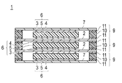
図1は、本発明を適用したバイポーラ電池の構造を説明するための断面図であり、図2は、このバイポーラ電池を構成する単電池の部分拡大断面図である。
【0015】
バイポーラ電池1は、両端部以外の一つの集電体2の両面中央に正極活物質層3と負極活物質層4が形成されており、この集電体2の正極活物質層3と負極活物質層4との間に電解質層5を挟んで単電池層6を構成し、この単電池層6が複数積層された構造を持つ。なお、両端部にある集電体(端部集電体7と称する)は、このバイポーラ電池全体の電極と接続される。
【0016】
そして、集電体2を挟んで正極活物質層3と負極活物質層4を設けた構成をバイポーラ電極という。
【0017】
ここで、電解質層5は、たとえば、ポリマー骨格中に、数重量%〜98重量%程度電解液を保持させたゲル電解質で、特に本実施の形態においては、70重量%以上電解液を保持したゲル電解質を使用することができる。
【0018】
このバイポーラ電池1では、単電池層6からの液漏れを防止するために、一つひとつの単電池層6の周囲を取り囲み、集電体2間、または、集電体2および端部集電体7の間に配置される両面粘着部材9を設けている。
【0019】
両面粘着部材9は、基材10と、該基材10の両面に設けられた粘着剤11とを含んでなる両面テープである。基材10は、ポリプロピレン(PP)、ポリエチレン(PE)、ポリアミド系合成繊維などの絶縁性樹脂により形成されている。粘着剤11は、合成ゴム、ブチルゴム、合成樹脂、アクリルなどの耐溶剤性のある材料により形成されている。このような材料を両面粘着部材9に用いることによって、単電池層6からの液漏れを防止することができ、また集電体同士の接触による短絡を防止することができる。
【0020】
次に、本発明のバイポーラ電池1の製造手順について説明する。
【0021】
図3〜図7は本発明のバイポーラ電池の製造手順を説明するための図である。
【0022】
図3は集電体上にゲル電解質層および両面粘着部材を積層する様子を示す図、図4は両面粘着部材を積層した様子を示す図、図5は図4に示す積層物のA−A断面図、図6は単セルを積層する様子を示す平面図、図7は単セルを積層する様子を示す側面図である。
【0023】
本発明のバイポーラ電池1の製造手順としては、図3に示すように、まず、端部集電体7上に電極層(正極活物質層3または負極活物質層4、例えば、正極活物質層3)を積層し、その上にさらにゲル電解質層5を積層する。そして、端部集電体7の縁上に両面粘着部材9を配置する。ここで、両面粘着部材9は、端部集電体7の縁のみを覆うように、中央に貫通孔が形成されている。
【0024】
このように両面粘着部材9まで積層されると、図4に示すように、両面粘着部材9は、ゲル電解質層5の周りを取り囲むように配置される。ここで、両面粘着部材9は両面に粘着剤11が設けられているので、集電体7上に積層された瞬間に接着される。
【0025】
なお、両面粘着部材9の厚さは、図5に示すように、正極活物質層3およびゲル電解質層5の厚さより厚い。両面粘着部材9の厚さとしては、正極活物質層3、ゲル電解質層5、および、後に積層する負極活物質層4の合計の厚さ、すなわち、単電池層6の厚さの±30μm以内であることが望ましい。単電池層6の合計厚さに両面粘着部材9の厚さをあわせることによって、積層数の増加に伴う集電体2、7の歪みを防止でき、歪みによる反応性の低下、短絡を防止することができる。また、両面粘着部材9の幅は、バイポーラ電池1の小型化の要請から5mm程度が望ましい。
【0026】
以上のように積層された端部集電体7、正極活物質層3、ゲル電解質層5、および両面粘着部材9を単セル12と称する。なお、バイポーラ電池1の中部に位置する単セル13については、集電体2の両面に電極層を設け、たとえば、上面に正極活物質層3を設け下面に負極活物質層4を設けたものをいう。すなわち、負極活物質層4、集電体2、正極活物質層3を積層してなるバイポーラ電極上にゲル電解質層5を積層し、集電体2の縁に両面粘着部材9を積層したものを単セル13とする。単セル13の積層数を増やすことによって、バイポーラ電池1を所望の積層数にすることができる。
【0027】
また、バイポーラ電池1の最後に積層する単セル14は、上述の最初に積層する単セル12とは異なり、負極活物質層4に端部集電体7を積層したものをいう。
【0028】
このように、単セル12〜14を一単位として、複数の単セルを予め製作しておき、バイポーラ電池1に必要な個数だけ積層する。単セル12〜14を積層する様子について説明する。
【0029】
図6および図7に示すように、最初の単セル12に、中部の単セル13を積層する。これを繰り返すことによって、単セル12上の単セル13の積層数が増加する。単セル12に単セル13を積層した場合、単セル12の両面粘着部材9の粘着剤11が単セル13の集電体2の下面に接着される。同様に、単セル13上に他の単セル13を積層した場合にも、下側の単セル13の粘着剤11が上側の単セル13の集電体2の下面に接着される。このように、両面粘着部材9は、単セル13が積層されていくたびに集電体2と接着されていき、ゲル電解質層5を密閉していく。これによりゲル電解質層5からの液漏れを防止することができる。
【0030】
最後に、図7に示すように、単セル14を積層して、該単セル14の集電体7が単セル13の両面粘着部材9と接着されることにより、バイポーラ電池1が完成する。
【0031】
以上のように、本発明のバイポーラ電池1では、単電池層6と共に該単電池層6を囲い込むように両面粘着部材9が集電体間に配置されるようにしたので、両面粘着部材9が2つの集電体間に接着されることによりシール層の役割を果たし、単電池層6のゲル電解質層5からの液漏れを防止することができる。したがって、液漏れによる液絡も未然に防止することができる。加えて、両面粘着部材9により、外部からの水分等の浸入を防止することができ、バイポーラ電池自体の強度を向上することができる。
【0032】
また、ゲル電解質層5に含まれる電解液の割合が70重量%以上で、ゲル電解質層5の液化が起こりやすい場合でも、液漏れがないので液絡を防止することができる。
【0033】
さらに、本発明のバイポーラ電池1では、単セル12〜14の積層により形成されるので、単セルの製造時にはバイポーラ電池1の積層数を考慮することなく大量に製造しておき、個別のバイポーラ電池1の製造時に必要な単セル12〜14を用意すれば足りる。したがって、単セルの製造と、バイポーラ電池1の製造という2段階に分けることができるので、設計変更による積層数の変更にも柔軟に対応することができ、加えて、作業時間を短縮することができる。
【0034】
上記バイポーラ電池1について、両面粘着部材9以外の電池を構成する部材は、一般的なリチウムイオン二次電池に用いられているものと同じでよい。
【0035】
以下に、このバイポーラ電池1に使用することのできる集電体、正極、負極、ゲル電解質等について説明する。
【0036】
[集電体]
集電体は、製法上、スプレーコートなどの薄膜製造技術により、いかような形状を有するものにも製膜積層して形成し得る必要上、たとえば、アルミニウム、銅、チタン、ニッケル、ステンレス鋼(SUS)、これらの合金などの金属粉末を主成分として、これにバインダー(樹脂)、溶剤を含む集電体金属ペーストを加熱して成形してなるものであり、上記金属粉末およびバインダーにより形成されてなるものである。また、これら金属粉末を1種単独で用いてもよいし、2種以上を混合して用いてもよいし、さらに、製法上の特徴を生かして金属粉末の種類の異なるものを多層に積層したものであってもよい。
【0037】
上記バインダーとしては、特に制限されるべきものではなく、たとえば、エポキシ樹脂など、従来公知の樹脂バインダー材料を用いることができるほか、導電性高分子材料を用いても良い。
【0038】
集電体の厚さは、特に限定されないが、通常は1〜100μm程度である。
【0039】
[正極活物質層]
正極は、正極活物質を含む。この他にも、イオン伝導性を高めるために電解質、リチウム塩などが含まれ得る。また、電子伝導性を高めるために導電助剤、スラリー粘度の調整溶媒としてNMP(N−メチル−2−ピロリドン)、重合開始材としてAIBN(アゾビスイソブチロニトリル)などが含まれ得る。特に、正極または負極の少なくとも一方に電解質、好ましくは固体高分子電解質が含まれていることが望ましいが、バイポーラ電池の電池特性をより向上させるためには、双方に含まれることが好適である。
【0040】
上記正極活物質としては、溶液系のリチウムイオン電池でも使用される、遷移金属とリチウムとの複合酸化物を使用できる。具体的には、LiCoO2などのLi・Co系複合酸化物、LiNiO2などのLi・Ni系複合酸化物、スピネルLiMn2O4などのLi・Mn系複合酸化物、LiFeO2などのLi・Fe系複合酸化物などが挙げられる。この他、LiFePO4などの遷移金属とリチウムのリン酸化合物や硫酸化合物;V2O5、MnO2、TiS2、MoS2、MoO3などの遷移金属酸化物や硫化物;PbO2、AgO、NiOOHなどが挙げられる。
【0041】
正極活物質の粒径は、製法上、正極材料をペースト化してスプレーコートなどにより製膜し得るものであればよい。さらにバイポーラ電池の電極抵抗を低減するために、電解質が固体でない溶液タイプのリチウムイオン電池で用いられ一般に用いられる粒径よりも小さいものを使用するとよい。具体的には、正極活物質の平均粒径が10〜0.1μmであるとよい。
【0042】
上記正極に含まれる電解質としては、固体高分子電解質、高分子ゲル電解質、およびこれらを積層したものなどが利用できる。すなわち、正極を多層構造とすることもでき、集電体側と電解質側とで、正極を構成する電解質の種類や活物質の種類や粒径、さらにはこれらの配合比を変えた層を形成することもできる。
【0043】
高分子ゲル電解質は、イオン導伝性を有する固体高分子電解質に、通常リチウムイオン電池で用いられる電解液を含んだものであるが、さらに、リチウムイオン導伝性を持たない高分子の骨格中に、同様の電解液を保持させたものも含まれる。
【0044】
ここで、高分子ゲル電解質に含まれる電解液(電解質塩および可塑剤)としては、通常リチウムイオン電池で用いられるものであればよく、たとえば、LiPF6、LiBF4、LiClO4、LiAsF6、LiTaF6、LiAlCl4、Li2B10Cl10等の無機酸陰イオン塩、LiCF3SO3、Li(CF3SO2)2N、Li(C2F5SO2)2N等の有機酸陰イオン塩の中から選ばれる、少なくとも1種類のリチウム塩(電解質塩)を含み、プロピレンカーボネート、エチレンカーボネート等の環状カーボネート類;ジメチルカーボネート、メチルエチルカーボネート、ジエチルカーボネート等の鎖状カーボネート類;テトラヒドロフラン、2−メチルテトラヒドロフラン、1,4−ジオキサン、1,2−ジメトキシエタン、1,2−ジブトキシエタン等のエーテル類;γ−ブチロラクトン等のラクトン類;アセトニトリル等のニトリル類;プロピオン酸メチル等のエステル類;ジメチルホルムアミド等のアミド類;酢酸メチル、蟻酸メチルの中から選ばれる少なくともから1種類または2種以上を混合した、非プロトン性溶媒等の有機溶媒(可塑剤)を用いたものなどが使用できる。ただし、これらに限られるわけではない。
【0045】
高分子ゲル電解質に用いられるリチウムイオン導伝性を持たない高分子としては、たとえば、ポリフッ化ビニリデン(PVDF)、ポリビニルクロライド(PVC)、ポリアクリロニトリル(PAN)、ポリメチルメタクリレート(PMMA)などが使用できる。ただし、これらに限られるわけではない。なお、PAN、PMMAなどは、どちらかと言うとイオン伝導性がほとんどない部類に入るものであるため、上記イオン伝導性を有する高分子とすることもできるが、ここでは高分子ゲル電解質に用いられるリチウムイオン導伝性を持たない高分子として例示したものである。
【0046】
上記リチウム塩としては、たとえば、LiPF6、LiBF4、LiClO4、LiAsF6、LiTaF6、LiAlCl4、Li2B10Cl10等の無機酸陰イオン塩、Li(CF3SO2)2N、Li(C2F5SO2)2N等の有機酸陰イオン塩、またはこれらの混合物などが使用できる。ただし、これらに限られるわけではない。
【0047】
導電助剤としては、アセチレンブラック、カーボンブラック、グラファイト等が挙げられる。ただし、これらに限られるわけではない。
【0048】
正極における、正極活物質、電解質(好ましくは固体高分子電解質)、リチウム塩、導電助剤の配合量は、電池の使用目的(出力重視、エネルギー重視など)、イオン伝導性を考慮して決定すべきである。たとえば、正極内における電解質、特に固体高分子電解質の配合量が少なすぎると、活物質層内でのイオン伝導抵抗やイオン拡散抵抗が大きくなり、電池性能が低下してしまう。一方、正極内における電解質、特に固体高分子電解質の配合量が多すぎると、電池のエネルギー密度が低下してしまう。従って、これらの要因を考慮して、目的に合致した固体高分子電解質量を決定する。
【0049】
正極の厚さは、特に限定するものではなく、配合量について述べたように、電池の使用目的(出力重視、エネルギー重視など)、イオン伝導性を考慮して決定すべきである。一般的な正極活物質層の厚さは10〜500μm程度である。
【0050】
[負極活物質層]
負極は、負極活物質を含む。この他にも、イオン伝導性を高めるために電解質、リチウム塩や導電助剤などが含まれ得る。負極活物質の種類以外は、基本的に「正極活物質層」の項で記載した内容と同様であるため、ここでは説明を省略する。
【0051】
負極活物質としては、溶液系のリチウムイオン電池でも使用される負極活物質を用いることができる。たとえば、金属酸化物、リチウム−金属複合酸化物金属、カーボンなどが好ましい。より好ましくは、カーボン、遷移金属酸化物、リチウム−遷移金属複合酸化物である。さらに好ましくは、チタン酸化物、リチウム−チタン複合酸化物、カーボンである。これらは1種単独で用いてもよいし、2種以上を併用してもよい。
【0052】
[電解質]
電解質としては、高分子ゲル電解質である。この電解質は多層構造とすることもでき、正極側と負極側とで、電解質の種類や成分配合比を変えた層を形成することもできる。高分子ゲル電解質を用いる場合、該高分子ゲル電解質を構成するポリマーと電解液との比率(質量比)が、20:80〜2:98と比較的電解液の比率が大きい範囲である。
【0053】
このような高分子ゲル電解質としては、イオン導伝性を有する固体高分子電解質に、通常リチウムイオン電池で用いられる電解液を含んだものであるが、さらに、リチウムイオン導伝性を持たない高分子の骨格中に、同様の電解液を保持させたものも含まれるものも含まれる。これらについては、[正極]に含まれる電解質の1種として説明した高分子ゲル電解質と同様であるため、ここでの説明は省略する。
【0054】
これら固体高分子電解質もしくは高分子ゲル電解質は、電池を構成する高分子電解質のほか、上記したように正極および/または負極にも含まれ得るが、電池を構成する高分子電解質、正極、負極によって異なる高分子電解質を用いてもよいし、同一の高分子電解質を使用してもよいし、層によって異なる高分子電解質を用いてもよい。
【0055】
電池を構成する電解質の厚さは、特に限定するものではない。しかしながら、コンパクトなバイポーラ電池を得るためには、電解質としての機能が確保できる範囲で極力薄くすることが好ましい。一般的な固体高分子電解質層の厚さは10〜100μm程度である。ただし、電解質の形状は、製法上の特徴を生かして、電極(正極または負極)の上面ならびに側面外周部も被覆するように形成することも容易であり、機能、性能面からも部位によらず常に略一定の厚さにする必要はない。
【0056】
[電池外装材(電池ケース)]
バイポーラ電池は、外部からの衝撃、環境劣化を防止するために、使用する際の外部からの衝撃、環境劣化を防止するために、バイポーラ電池本体である型板を含めた電池積層体全体を電池外装材ないし電池ケース(図示せず)に収容するとよい。
【0057】
軽量化の観点からは、アルミニウム、ステンレス、ニッケル、銅などの金属(合金を含む)をポリプロピレンフィルム等の絶縁体で被覆した高分子−金属複合ラミネートフィルムやアルミラミネートパックなど、従来公知の電池外装材を用いて、その周辺部の一部または全部を熱融着にて接合することにより、電池積層体を収納し密封した構成とするのが好ましい。
【0058】
この場合、上記正極および負極リードは、上記熱融着部に挟まれて上記電池外装材の外部に露出される構造とすればよい。また、熱伝導性に優れた高分子−金属複合ラミネートフィルムやアルミラミネートパックなどを用いることが、自動車の熱源から効率よく熱を伝え、電池内部を電池動作温度まですばやく加熱することができる点で好ましい。
【0059】
[正極および負極端子板]
正極および負極端子板は、端子としての機能を有するほか、薄型化の観点からは極力薄い方がよいが、製膜により積層されてなる電極、電解質および集電体はいずれも機械的強度が弱いため、これらを両側から挟示し支持するだけの強度を持たせることが望ましい。さらに、端子部での内部抵抗を抑える観点から、正極および負極端子板の厚さは、通常0.1〜2mm程度が望ましいといえる。
【0060】
正極および負極端子板の材質は、通常リチウムイオン電池で用いられる材質を用いることができる。たとえば、アルミニウム、銅、チタン、ニッケル、ステンレス鋼(SUS)、これらの合金などを利用することができる。耐蝕性、作り易さ、経済性などの観点からは、アルミニウムを用いることが好ましい。
【0061】
正極端子板と負極端子板との材質は、同一の材質を用いてもよいし、異なる材質のものを用いてもよい。さらに、これら正極および負極端子板は、材質の異なるものを多層に積層したものであってもよい。
【0062】
正極および負極端子板の形状は、型板と兼用する場合には、自動車の熱源外面等をトレースした形状に、また、型板と対極する位置に設けられる端子板では、該端子板を設置する集電体外面をトレースした形状であればよく、プレス成形等によりトレースして形成すればよい。なお、型板と対極する位置に設けられる端子板では、集電体と同様にスプレーコートにより形成してもよい。
【0063】
[正極および負極リード]
正極および負極リードに関しては、通常リチウムイオン電池で用いられる公知のリードを用いることができる。なお、電池外装材(電池ケース)から取り出された部分は、自動車の熱源との距離がないことから、これらに接触して漏電したりして自動車部品(特に電子機器)に影響を与えないように、耐熱絶縁性の熱収縮チューブなどにより被覆しておくのが好ましい。
【0064】
図8は、図1および2に示したバイポーラ電池1をアルミラミネートパックにより電池20として構成した場合の外観を示す図面である。この電池20は、バイポーラ電池1の端部集電体7に上記の正極および負極端子板を設け、さらにリードを取り付けて、電極23および24としている。
【0065】
次に、実際上記バイポーラ電池1を製作して評価を行った実験例について説明する。
【0066】
実験例
<液絡評価>
上述した実施の形態と同様にしてバイポーラ電池1を製作し、単電池同士の液絡の評価を行った。
【0067】
(サンプル作製)
実施例として実際に作製したバイポーラ電池1は、下記の通りである。
【0068】
集電体2は、20μmのステンレス(SUS)箔を使用し、端部集電体7には正極活物質層3または負極活物質層4を形成し、集電体2には正極活物質層3および負極活物質層4を形成した。
【0069】
正極活物質層3は、LiMn2O4に、導電助剤としてアセチレンブラック、バインダーとしてポリフッ化ビニリデン(PVDF)、粘度調整溶媒としてN−メチル−2−ピロリドン(NMP)を混合して正極スラリーを作製し、これを正極活物質として、集電体であるステンレス箔(厚さ20μm)の片面に塗布し、乾燥させて膜厚40μmの正極活物質層3としている。
【0070】
負極活物質層4は、Li4Ti5O12に、導電助剤としてアセチレンブラック、バインダーとしてPVDF、粘度調整溶媒としてNMP、混合して負極スラリーを作製し、この負極スラリーを正極活物質層3を塗布したステンレス箔の反対面に塗布し、乾燥させて膜厚50μmの負極活物質層4としている。
【0071】
高分子ゲル電解質層5は、厚さ100μmのポリプロピレン(PP)不識布に、ポリマー(ポリエチレンオキシドとポリプロピレンオキシドの共重合体)5重量%、混合比1:3のエチレンカーボネート(EC)+ジメチルカーボネート(DMC)95重量%、EC+DMC電解液に対して1.0mol/lのLi(C2F5SO2)2N、からなるゲル電解質を保持させたものである。
【0072】
両面粘着部材9は、基材10にポリプロピレン(PP)を用い、粘着剤11に合成ゴムを用いて、幅5mm、厚さ190μmのものを用意した。
【0073】
単電池層6の積層数は5層とし、単セル12〜14の積層時に両面粘着部材9の粘着剤11により各単セル間を接着およびシーリングした。
【0074】
また、この評価の比較例として、両面粘着部材9を持たない、同様構造のパイポーラ電池を形成した。
【0075】
液絡の評価は、実施例および比較例のバイポーラ電池1の充放電サイクル試験を行うことにより評価した。充放電のサイクルは、0.5Cの電流で充電し、0.5Cの電流で放電を行い、これを1サイクルとした。
【0076】
(評価結果)
実施例のバイポーラ電池1では、充放電サイクルを50サイクル超えても電極間の液絡(短絡)は起こらず、出力電圧が維持されていた。
【0077】
一方、比較例のバイポーラ電池1では、初回の充電を行っている途中に、電解液が単電池層外に染み出し、他の単電池層の電解質層5と接触して液絡が起こり、電池電圧が著しく低下した。
【0078】
この評価結果から、単電池層6ごとに、これを取り囲む両面粘着部材9を設けることで、単電池同士の液絡を確実に防止できることがわかる。
【0079】
<両面粘着部材9の厚さ試験>
次に、両面粘着部材9の厚さを変えて試験を行った。
【0080】
(サンプル作製)
実施例として作製したバイポーラ電池1は、上記<液絡評価>と同一構造である。実施例のバイポーラ電池が有する両面粘着部材9の厚さは、単電池層6の厚さ、すなわち、正極活物質層3(40μm)、ゲル電解質層5(100μm)、負極活物質層4(50μm)の合計厚さに合わせて190μmである。
【0081】
評価の比較例としては、両面粘着部材9の厚さのみ異なるバイポーラ電池を作製した。比較例1〜6として、順に、両面粘着部材9の厚さを100μm、120μm、160μm、220μm、260μm、300μmのバイポーラ電池を作製した。
【0082】
厚さの評価は、実施例および比較例1〜6のバイポーラ電池について、それぞれ、10回充放電サイクルを繰り返し、10サイクル目の放電容量を比較した。充放電のサイクルは、0.5Cの電流で充電し、0.5Cの電流で放電を行い、これを1サイクルとした。
【0083】
(評価結果)
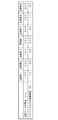
図9は両面粘着部材の厚さに対する放電容量についての評価結果を示す図である。図9では、実施例のバイポーラ電池(厚さ190μm)の10サイクル目の放電容量を100%として、比較例の放電容量について示している。図9に示すように、比較例3および比較例4では、比較的放電容量が大きく、比較例1,2、5、6では放電容量が著しく低下した。
【0084】
この評価結果から、両面粘着部材9の厚さが単電池層6の厚さに近いほど放電容量がよく、単電池層の厚さに対して両面粘着部材9の厚さが誤差30μm程度であれば、電池の性能を保てることがわかる。
【0085】
(第2の実施の形態)
本発明の第3は、上記第1の実施の形態のバイポーラ電池1を複数個、並列および/または直列に接続してなる組電池である。
【0086】
図10は、第2の実施の形態による組電池の斜視図であり、図11は、内部構成を上方から見た図面である。
【0087】
図10および図11に示すように組電池50は、上述した第1の実施の形態によるバイポーラ電池1をラミネートパックによりパッケージした電池20(図8参照)複数個直接に接続したものをさらに並列に接続したものである。電池20同士は、導電バー53により各電池の電極23および24が接続されている。この組電池50には電極ターミナル51および52が、この組電池50の電極として組電池50の一側面に設けられている。
【0088】
この組電池においては、電池20を直接に接続しさらに並列に接続する際の接続方法として、超音波溶接、熱溶接、レーザー溶接、リベット、かしめ、電子ビームなどを用いることができる。このような接続方法をとることで、長期的信頼性のある組電池を製造することができる。
【0089】
本第2の実施の形態による組電池によれば、前述した第1の実施の形態による電池を用いて組電池化することで、高容量、高出力と得ることができ、しかも一つひとつの電池の信頼性が高いため、組電池としての長期的信頼性を向上させることができる。
【0090】
なお、組電池としての電池20の接続は、電池20を複数個全て並列に接続してもよいし、また、電池20を複数個全て直列に接続してもよい。
【0091】
(第3の実施の形態)
本発明の第4は、上記第1実施形態のバイポーラ電池1または第2実施形態の組電池50を駆動用電源として搭載してなる車両である。バイポーラ電池1または組電池50をモータ用電源として用いる車両としては、たとえば電気自動車、ハイブリッド自動車など、車輪をモータによって駆動している自動車である。
【0092】
参考までに、図12に、組電池50を搭載する自動車100の概略図を示す。自動車に搭載される組電池50は、上記説明した特性を有する。このため、組電池50を搭載してなる自動車は高い耐久性を有し、長期間に渡って使用した後であっても充分な出力を提供しうる。
【図面の簡単な説明】
【図1】 本発明を適用したバイポーラ電池の構造を説明するための断面図である。
【図2】 このバイポーラ電池を構成する単電池の部分拡大断面図である。
【図3】 集電体上にゲル電解質層および両面粘着部材を積層する様子を示す図である。
【図4】 両面粘着部材を積層した様子を示す図、図5は図4に示す積層物の部分断面図である。
【図5】 図4に示す積層物のA−A断面図である。
【図6】 単セルを積層する様子を示す平面図である。
【図7】 単セルを積層する様子を示す側面図である。
【図8】 バイポーラ電池をラミネートパックにした電池の外観を示す斜視図である。
【図9】 両面粘着部材の厚さに対する放電容量についての評価結果を示す図である。
【図10】 組電池の斜視図である。
【図11】 組電池の内部構成を上方から見た図面である。
【図12】 組電池を搭載する自動車の概略図である。
【符号の説明】、
1…バイポーラ電池、
2…集電体、
3…正極活物質層、
4…負極活物質層、
5…ゲル電解質層、
6…単電池層、
7…端部集電体、
9…両面粘着部材、
10…基材、
11…粘着剤、
12〜14…単セル、
50…組電池、
100…自動車。[0001]
BACKGROUND OF THE INVENTION
The present invention relates to a bipolar battery, and more particularly to a bipolar battery using a polymer gel electrolyte as an electrolyte, a method for manufacturing the bipolar battery, a battery pack, and a vehicle equipped with the bipolar battery.
[0002]
[Prior art]
Lithium secondary batteries include those using a solid electrolyte, those using a liquid electrolyte, and those using a polymer gel electrolyte as the electrolyte enclosed therein.
[0003]
For the solid electrolyte, for example, an all solid polymer electrolyte such as polyethylene oxide is used, while for the liquid electrolyte, a 100% electrolytic solution is used. The polymer gel electrolyte should be said to be an intermediate between them. For example, polyvinylidene fluoride (PVDF) itself has an electrolyte solution held in a polymer skeleton having no lithium ion conductivity ( For example, see Patent Document 1.)
[0004]
[Patent Document 1]
Japanese Patent Laid-Open No. 11-204136
[Problems to be solved by the invention]
When a single cell layer is formed using this polymer gel electrolyte and a bipolar battery is manufactured by laminating a plurality of the single cell layers, the electrolyte oozes out between each single cell layer and contacts the electrolyte of other single cell layers. As a result, there is a problem that a short circuit between the cell layers called liquid junction occurs.
[0006]
Therefore, an object of the present invention is to provide a bipolar battery in which a liquid junction between the single battery layers is prevented even when a battery is configured by laminating a plurality of single battery layers using a polymer gel electrolyte.
[0007]
[Means for Solving the Problems]
In the first aspect of the present invention, a bipolar electrode in which a positive electrode active material layer is formed on one surface of a current collector and a negative electrode active material layer is formed on the other surface is laminated with a gel electrolyte layer interposed therebetween. A battery having a double-sided pressure-sensitive adhesive member disposed so as to surround a single cell layer including the adjacent positive electrode active material layer, the gel electrolyte layer, and the negative electrode active material layer; The double-sided pressure-sensitive adhesive member comprises an insulating material serving as a base material and a pressure-sensitive adhesive provided on both surfaces of the insulating material, and is sandwiched between two current collectors together with the single cell layer by the pressure-sensitive adhesive. This is a bipolar battery bonded between two current collectors.
[0008]
In the second aspect of the present invention, at least one of a positive electrode active material layer, a gel electrolyte layer, and a negative electrode active material layer is laminated at the center of the current collector, and further, a substrate and the substrate are formed on the edge of the current collector. Bipolar that creates a plurality of single cells formed by laminating double-sided pressure-sensitive adhesive members each having a pressure-sensitive adhesive provided on both sides of the material, laminates the single cells, and bonds the single cells to each other with the pressure-sensitive adhesive of the double-sided pressure-sensitive adhesive member It is a manufacturing method of a battery.
[0009]
【The invention's effect】
According to the first bipolar battery of the present invention, the double-sided pressure-sensitive adhesive member disposed so as to surround the single cell layer is bonded between the two current collectors, thereby serving as a seal layer. Therefore, it is possible to prevent short circuit due to leakage of the gel electrolyte, to prevent moisture and the like from entering from the outside, and to improve the strength of the bipolar battery itself.
[0010]
According to the second method for manufacturing a bipolar battery of the present invention, single cells are prepared first, and then the single cells are stacked and bonded. Therefore, the number of bipolar batteries stacked is taken into account when manufacturing the single cells. It is sufficient to manufacture a large number of the cells without any problem and prepare single cells necessary for manufacturing individual bipolar batteries. Therefore, since it can be divided into two stages, that is, the production of a single cell and the production of a bipolar battery, it is possible to flexibly cope with a change in the number of stacks due to a design change, and in addition, the working time can be shortened. .
[0011]
DETAILED DESCRIPTION OF THE INVENTION
Embodiments of the present invention will be described below with reference to the drawings. In the following drawings, each component is exaggerated for clarity of explanation.
[0012]
(First embodiment)
In the first aspect of the present invention, a bipolar electrode in which a positive electrode active material layer is formed on one surface of a current collector and a negative electrode active material layer is formed on the other surface is laminated with a gel electrolyte layer interposed therebetween. A battery having a double-sided pressure-sensitive adhesive member disposed so as to surround a single cell layer including the adjacent positive electrode active material layer, the gel electrolyte layer, and the negative electrode active material layer; The double-sided pressure-sensitive adhesive member comprises an insulating material serving as a base material and a pressure-sensitive adhesive provided on both surfaces of the insulating material, and is sandwiched between two current collectors together with the single cell layer by the pressure-sensitive adhesive. This is a bipolar battery bonded between two current collectors.
[0013]
In the second aspect of the present invention, at least one of a positive electrode active material layer, a gel electrolyte layer, and a negative electrode active material layer is laminated at the center of the current collector, and further, a substrate and A plurality of single cells formed by laminating double-sided pressure-sensitive adhesive members each having a pressure-sensitive adhesive provided on both surfaces of the base material are laminated, and the single cells are laminated, and the single cells are bonded together by the pressure-sensitive adhesive of the double-sided pressure-sensitive adhesive member. A method for manufacturing a bipolar battery.
[0014]
FIG. 1 is a cross-sectional view for explaining the structure of a bipolar battery to which the present invention is applied, and FIG. 2 is a partially enlarged cross-sectional view of a unit cell constituting the bipolar battery.
[0015]
In the bipolar battery 1, a positive electrode
[0016]
And the structure which provided the positive electrode
[0017]
Here, the
[0018]
In this bipolar battery 1, in order to prevent liquid leakage from the
[0019]
The double-sided pressure-sensitive
[0020]
Next, the manufacturing procedure of the bipolar battery 1 of the present invention will be described.
[0021]
3-7 is a figure for demonstrating the manufacturing procedure of the bipolar battery of this invention.
[0022]
3 is a view showing a state where a gel electrolyte layer and a double-sided pressure-sensitive adhesive member are laminated on a current collector, FIG. 4 is a view showing a state where a double-sided pressure-sensitive adhesive member is laminated, and FIG. 5 is an AA of the laminate shown in FIG. FIG. 6 is a cross-sectional view, FIG. 6 is a plan view showing how single cells are stacked, and FIG. 7 is a side view showing how single cells are stacked.
[0023]
As a manufacturing procedure of the bipolar battery 1 of the present invention, as shown in FIG. 3, first, an electrode layer (positive electrode
[0024]
When the double-sided pressure-
[0025]
In addition, the thickness of the double-
[0026]
The end
[0027]
The
[0028]
In this way, a plurality of single cells are manufactured in advance with the
[0029]
As shown in FIGS. 6 and 7, the
[0030]
Finally, as shown in FIG. 7, the
[0031]
As described above, in the bipolar battery 1 of the present invention, the double-sided pressure-
[0032]
Further, even when the ratio of the electrolytic solution contained in the
[0033]
Furthermore, since the bipolar battery 1 of the present invention is formed by stacking the
[0034]
Regarding the bipolar battery 1, members constituting the battery other than the double-
[0035]
The current collector, positive electrode, negative electrode, gel electrolyte, etc. that can be used for the bipolar battery 1 will be described below.
[0036]
[Current collector]
The current collector needs to be formed by laminating and stacking whatever shape it has, such as aluminum, copper, titanium, nickel, stainless steel (for example, by a thin film manufacturing technique such as spray coating). SUS), a metal powder such as an alloy thereof as a main component, and a current collector metal paste containing a binder (resin) and a solvent is heated and molded, and is formed by the metal powder and the binder. It will be. In addition, these metal powders may be used alone or in combination of two or more, and moreover, different types of metal powders are laminated in multiple layers taking advantage of the characteristics of the manufacturing method. It may be a thing.
[0037]
The binder is not particularly limited. For example, a conventionally known resin binder material such as an epoxy resin can be used, and a conductive polymer material may be used.
[0038]
Although the thickness of a collector is not specifically limited, Usually, it is about 1-100 micrometers.
[0039]
[Positive electrode active material layer]
The positive electrode includes a positive electrode active material. In addition to this, an electrolyte, a lithium salt, or the like may be included in order to increase ion conductivity. Moreover, in order to improve electronic conductivity, a conductive support agent, NMP (N-methyl-2-pyrrolidone) as a solvent for adjusting slurry viscosity, AIBN (azobisisobutyronitrile) as a polymerization initiator, and the like may be included. In particular, it is desirable that at least one of the positive electrode and the negative electrode contains an electrolyte, preferably a solid polymer electrolyte. However, in order to further improve the battery characteristics of the bipolar battery, it is preferable to contain them in both.
[0040]
As the positive electrode active material, a composite oxide of transition metal and lithium, which is also used in a solution-type lithium ion battery, can be used. Specifically, Li · Co-based composite oxide such as LiCoO 2, Li · Ni-based composite oxide such as LiNiO 2, Li · Mn-based composite oxide such as spinel LiMn 2 O 4, Li · such LiFeO 2 Examples thereof include Fe-based composite oxides. In addition, transition metal and lithium phosphate compounds and sulfuric acid compounds such as LiFePO 4 ; transition metal oxides and sulfides such as V 2 O 5 , MnO 2 , TiS 2 , MoS 2 , and MoO 3 ; PbO 2 , AgO, NiOOH etc. are mentioned.
[0041]
The positive electrode active material may have any particle diameter as long as the positive electrode material can be formed into a paste by spray coating or the like. Further, in order to reduce the electrode resistance of the bipolar battery, it is preferable to use a battery whose electrolyte is smaller than a particle diameter generally used in a solution type lithium ion battery which is not solid. Specifically, the average particle diameter of the positive electrode active material is preferably 10 to 0.1 μm.
[0042]
As the electrolyte contained in the positive electrode, a solid polymer electrolyte, a polymer gel electrolyte, a laminate of these, and the like can be used. That is, the positive electrode can have a multi-layer structure, and on the collector side and the electrolyte side, a layer in which the type of electrolyte constituting the positive electrode, the type and particle size of the active material, and the mixing ratio thereof are changed is formed. You can also.
[0043]
The polymer gel electrolyte is a solid polymer electrolyte having ion conductivity containing an electrolyte solution usually used in a lithium ion battery. Further, in the polymer skeleton having no lithium ion conductivity, In addition, those holding the same electrolytic solution are also included.
[0044]
Here, as the electrolyte solution (electrolyte salt and plasticizer) contained in the polymer gel electrolyte, any electrolyte solution that is usually used in a lithium ion battery may be used. For example, LiPF 6 , LiBF 4 , LiClO 4 , LiAsF 6 , LiTaF 6 , inorganic acid anion salts such as LiAlCl 4 and Li 2 B 10 Cl 10 , organic acid anions such as LiCF 3 SO 3 , Li (CF 3 SO 2 ) 2 N, Li (C 2 F 5 SO 2 ) 2 N Including at least one lithium salt (electrolyte salt) selected from ionic salts, cyclic carbonates such as propylene carbonate and ethylene carbonate; chain carbonates such as dimethyl carbonate, methyl ethyl carbonate, and diethyl carbonate; tetrahydrofuran, 2-methyltetrahydrofuran, 1,4-dioxane, 1,2-dimethoxyethane Ethers such as 1,2-dibutoxyethane; lactones such as γ-butyrolactone; nitriles such as acetonitrile; esters such as methyl propionate; amides such as dimethylformamide; methyl acetate and methyl formate The thing using organic solvents (plasticizer), such as an aprotic solvent, which mixed 1 type or 2 types or more from at least chosen can be used. However, it is not necessarily limited to these.
[0045]
For example, polyvinylidene fluoride (PVDF), polyvinyl chloride (PVC), polyacrylonitrile (PAN), polymethyl methacrylate (PMMA), etc. are used as the polymer having no lithium ion conductivity used in the polymer gel electrolyte. it can. However, it is not necessarily limited to these. Note that PAN, PMMA, etc. are in a class that has almost no ionic conductivity, and thus can be a polymer having the above ionic conductivity, but here, they are used for a polymer gel electrolyte. This is exemplified as a polymer having no lithium ion conductivity.
[0046]
As the lithium salt, for example, LiPF 6, LiBF 4, LiClO 4,
[0047]
Examples of the conductive assistant include acetylene black, carbon black, and graphite. However, it is not necessarily limited to these.
[0048]
The amount of the positive electrode active material, electrolyte (preferably solid polymer electrolyte), lithium salt, and conductive additive in the positive electrode is determined in consideration of the intended use of the battery (output priority, energy priority, etc.) and ion conductivity. Should. For example, if the amount of the electrolyte in the positive electrode, particularly the solid polymer electrolyte, is too small, the ionic conduction resistance and the ionic diffusion resistance in the active material layer will increase, and the battery performance will deteriorate. On the other hand, when the amount of the electrolyte in the positive electrode, particularly the solid polymer electrolyte, is too large, the energy density of the battery decreases. Therefore, in consideration of these factors, the solid polymer electrolysis mass suitable for the purpose is determined.
[0049]
The thickness of the positive electrode is not particularly limited, and should be determined in consideration of the intended use of the battery (emphasis on output, emphasis on energy, etc.) and ion conductivity, as described for the blending amount. A typical positive electrode active material layer has a thickness of about 10 to 500 μm.
[0050]
[Negative electrode active material layer]
The negative electrode includes a negative electrode active material. In addition to this, an electrolyte, a lithium salt, a conductive auxiliary agent, and the like may be included to enhance ion conductivity. Except for the type of the negative electrode active material, the contents are basically the same as those described in the section “Positive electrode active material layer”, and thus the description thereof is omitted here.
[0051]
As the negative electrode active material, a negative electrode active material that is also used in a solution-type lithium ion battery can be used. For example, metal oxide, lithium-metal composite oxide metal, carbon and the like are preferable. More preferred are carbon, transition metal oxide, and lithium-transition metal composite oxide. More preferred are titanium oxide, lithium-titanium composite oxide, and carbon. These may be used alone or in combination of two or more.
[0052]
[Electrolytes]
The electrolyte is a polymer gel electrolyte. This electrolyte can also have a multilayer structure, and a layer in which the type of electrolyte and the component blending ratio are changed can be formed on the positive electrode side and the negative electrode side. When the polymer gel electrolyte is used, the ratio (mass ratio) between the polymer constituting the polymer gel electrolyte and the electrolytic solution is 20:80 to 2:98, which is a range in which the ratio of the electrolytic solution is relatively large.
[0053]
As such a polymer gel electrolyte, a solid polymer electrolyte having ion conductivity includes an electrolytic solution usually used in a lithium ion battery. Those in which the same electrolyte solution is held in the molecular skeleton are also included. Since these are the same as the polymer gel electrolyte described as one of the electrolytes included in the [positive electrode], description thereof is omitted here.
[0054]
These solid polymer electrolytes or polymer gel electrolytes can be included in the positive electrode and / or the negative electrode as described above in addition to the polymer electrolyte constituting the battery, but depending on the polymer electrolyte, positive electrode, and negative electrode constituting the battery. Different polymer electrolytes may be used, the same polymer electrolyte may be used, or different polymer electrolytes may be used depending on the layer.
[0055]
The thickness of the electrolyte constituting the battery is not particularly limited. However, in order to obtain a compact bipolar battery, it is preferable to make it as thin as possible as long as the function as an electrolyte can be secured. The thickness of a general solid polymer electrolyte layer is about 10 to 100 μm. However, the shape of the electrolyte can be easily formed so as to cover the upper surface of the electrode (positive electrode or negative electrode) as well as the outer periphery of the side surface, taking advantage of the characteristics of the manufacturing method. It is not always necessary to have a substantially constant thickness.
[0056]
[Battery exterior material (battery case)]
In order to prevent external impact and environmental degradation, the bipolar battery is a battery that includes the entire battery stack including the template, which is the main body of the bipolar battery, in order to prevent external impact and environmental degradation during use. It may be housed in an exterior material or a battery case (not shown).
[0057]
From the viewpoint of weight reduction, conventionally known battery exteriors such as polymer-metal composite laminate films and aluminum laminate packs in which metals (including alloys) such as aluminum, stainless steel, nickel, and copper are coated with an insulator such as polypropylene film It is preferable that the battery stack is housed and sealed by joining a part or the whole of the peripheral part by heat fusion using a material.
[0058]
In this case, the positive electrode and the negative electrode lead may be structured to be sandwiched between the heat-sealed portions and exposed to the outside of the battery exterior material. In addition, the use of polymer-metal composite laminate films and aluminum laminate packs with excellent thermal conductivity allows heat to be efficiently transferred from the heat source of the automobile and the inside of the battery to be quickly heated to the battery operating temperature. preferable.
[0059]
[Positive electrode and negative electrode terminal plate]
The positive electrode and the negative electrode terminal plate have functions as terminals and are preferably as thin as possible from the viewpoint of thinning, but the electrodes, electrolytes, and current collectors that are laminated by film formation have low mechanical strength. For this reason, it is desirable to have sufficient strength to sandwich and support them from both sides. Furthermore, it can be said that the thickness of the positive electrode and the negative electrode terminal plate is usually preferably about 0.1 to 2 mm from the viewpoint of suppressing the internal resistance at the terminal portion.
[0060]
As the material of the positive electrode and the negative electrode terminal plate, materials usually used in lithium ion batteries can be used. For example, aluminum, copper, titanium, nickel, stainless steel (SUS), and alloys thereof can be used. Aluminum is preferably used from the viewpoints of corrosion resistance, ease of production, economy, and the like.
[0061]
The material of the positive electrode terminal plate and the negative electrode terminal plate may be the same material or different materials. Furthermore, the positive electrode and the negative electrode terminal plate may be a laminate of different materials.
[0062]
The shape of the positive electrode and the negative electrode terminal plate is a shape obtained by tracing the outer surface of a heat source of an automobile when used also as a template, and the terminal plate is installed in a terminal plate provided at a position opposite to the template. Any shape that traces the outer surface of the current collector may be used, and it may be formed by tracing by press molding or the like. Note that the terminal plate provided at a position opposite to the template may be formed by spray coating in the same manner as the current collector.
[0063]
[Positive electrode and negative electrode lead]
As for the positive electrode and the negative electrode lead, known leads usually used in lithium ion batteries can be used. In addition, since the part taken out from the battery exterior material (battery case) does not have a distance from the heat source of the automobile, it does not affect the automobile parts (particularly electronic equipment) by contacting with them and causing electric leakage. In addition, it is preferable to coat with a heat-resistant insulating heat-shrinkable tube or the like.
[0064]
FIG. 8 is a diagram showing an external appearance when the bipolar battery 1 shown in FIGS. 1 and 2 is configured as a
[0065]
Next, an experimental example in which the bipolar battery 1 is actually manufactured and evaluated will be described.
[0066]
Experimental example <liquid junction evaluation>
The bipolar battery 1 was manufactured in the same manner as in the above-described embodiment, and the liquid junction between the single cells was evaluated.
[0067]
(Sample preparation)
The bipolar battery 1 actually manufactured as an example is as follows.
[0068]
The
[0069]
The positive electrode
[0070]
The negative electrode
[0071]
The polymer
[0072]
The double-sided pressure-
[0073]
The number of single battery layers 6 was five, and the single cells were bonded and sealed with the adhesive 11 of the double-sided pressure-
[0074]
Further, as a comparative example of this evaluation, a bipolar battery having the same structure without the double-
[0075]
The liquid junction was evaluated by performing a charge / discharge cycle test of the bipolar battery 1 of the example and the comparative example. The charging / discharging cycle was performed by charging at a current of 0.5 C, and discharging was performed at a current of 0.5 C, and this was defined as one cycle.
[0076]
(Evaluation results)
In the bipolar battery 1 of the example, no liquid junction (short circuit) occurred between the electrodes even when the charge / discharge cycle exceeded 50 cycles, and the output voltage was maintained.
[0077]
On the other hand, in the bipolar battery 1 of the comparative example, during the first charge, the electrolyte oozes out of the single cell layer and contacts with the
[0078]
From this evaluation result, it can be seen that by providing the double-sided pressure-
[0079]
<Thickness test of double-
Next, the test was performed by changing the thickness of the double-sided pressure-
[0080]
(Sample preparation)
The bipolar battery 1 produced as an example has the same structure as the above <liquid junction evaluation>. The thickness of the double-sided pressure-
[0081]
As comparative examples for evaluation, bipolar batteries differing only in the thickness of the double-sided pressure-
[0082]
Thickness was evaluated by repeating 10 charge / discharge cycles for the bipolar batteries of Examples and Comparative Examples 1 to 6, respectively, and comparing the discharge capacities at the 10th cycle. The charging / discharging cycle was performed by charging at a current of 0.5 C, and discharging was performed at a current of 0.5 C, and this was defined as one cycle.
[0083]
(Evaluation results)
FIG. 9 is a diagram showing an evaluation result of the discharge capacity with respect to the thickness of the double-sided pressure-sensitive adhesive member. FIG. 9 shows the discharge capacity of the comparative example, assuming that the discharge capacity at the 10th cycle of the bipolar battery (
[0084]
From this evaluation result, the closer the thickness of the double-sided pressure-
[0085]
(Second Embodiment)
A third aspect of the present invention is an assembled battery formed by connecting a plurality of the bipolar batteries 1 of the first embodiment in parallel and / or in series.
[0086]
FIG. 10 is a perspective view of the assembled battery according to the second embodiment, and FIG. 11 is a view of the internal configuration as viewed from above.
[0087]
As shown in FIG. 10 and FIG. 11, the assembled
[0088]
In this assembled battery, ultrasonic welding, thermal welding, laser welding, rivet, caulking, electron beam, etc. can be used as a connection method when the
[0089]
According to the assembled battery according to the second embodiment, by using the battery according to the first embodiment described above, it is possible to obtain a high capacity and a high output by using the battery according to the first embodiment. Since reliability is high, long-term reliability as an assembled battery can be improved.
[0090]
In addition, connection of the
[0091]
(Third embodiment)
A fourth aspect of the present invention is a vehicle on which the bipolar battery 1 of the first embodiment or the assembled
[0092]
For reference, FIG. 12 shows a schematic diagram of an
[Brief description of the drawings]
FIG. 1 is a cross-sectional view for explaining the structure of a bipolar battery to which the present invention is applied.
FIG. 2 is a partial enlarged cross-sectional view of a unit cell constituting the bipolar battery.
FIG. 3 is a view showing a state in which a gel electrolyte layer and a double-sided pressure-sensitive adhesive member are laminated on a current collector.
4 is a view showing a state in which double-sided pressure-sensitive adhesive members are laminated, and FIG. 5 is a partial cross-sectional view of the laminate shown in FIG.
5 is a cross-sectional view of the laminate shown in FIG. 4 taken along the line AA.
FIG. 6 is a plan view showing a state in which single cells are stacked.
FIG. 7 is a side view showing a state in which single cells are stacked.
FIG. 8 is a perspective view showing an external appearance of a battery in which a bipolar battery is made into a laminate pack.
FIG. 9 is a diagram showing an evaluation result of the discharge capacity with respect to the thickness of the double-sided pressure-sensitive adhesive member.
FIG. 10 is a perspective view of an assembled battery.
FIG. 11 is a view of the internal configuration of the assembled battery as viewed from above.
FIG. 12 is a schematic view of an automobile equipped with an assembled battery.
[Explanation of symbols],
1 ... Bipolar battery,
2 ... current collector,
3 ... positive electrode active material layer,
4 ... negative electrode active material layer,
5 ... Gel electrolyte layer,
6 ... cell layer,
7 ... End current collector,
9: Double-sided adhesive member,
10 ... base material,
11 ... Adhesive,
12-14 ... single cell,
50 ... assembled battery,
100 ... an automobile.
Claims (7)
隣接する前記正極活物質層、前記ゲル電解質層、および前記負極活物質層を含んで構成される単電池層の周囲を取り囲むように配置される両面粘着部材を有し、
前記両面粘着部材は、基材の役割を果たす絶縁材と、該絶縁材の両面に設けられた粘着剤とからなり、前記単電池層と共に2つの集電体間に挟まれて前記粘着剤により該2つの集電体に接着されてなるバイポーラ電池。A bipolar battery in which a positive electrode active material layer is formed on one surface of a current collector and a negative electrode active material layer is formed on the other surface is a bipolar battery formed by laminating a gel electrolyte layer,
A double-sided pressure-sensitive adhesive member disposed so as to surround the periphery of a unit cell layer including the adjacent positive electrode active material layer, the gel electrolyte layer, and the negative electrode active material layer;
The double-sided adhesive member comprises an insulating material serving as a base material and an adhesive provided on both sides of the insulating material, and is sandwiched between two current collectors together with the single cell layer by the adhesive. A bipolar battery bonded to the two current collectors.
前記基材に、ポリプロピレン、ポリエチレン、ポリアミド系合成繊維からなる群から選択された樹脂が用いられ、
前記粘着剤に、合成ゴム、ブチルゴム、合成樹脂、アクリルからなる群から選択された耐溶剤性を有する材料が用いられている請求項1または請求項2に記載のバイポーラ電池。The double-sided adhesive member is
For the base material, a resin selected from the group consisting of polypropylene, polyethylene, and polyamide synthetic fibers is used.
The bipolar battery according to claim 1 or 2, wherein a material having a solvent resistance selected from the group consisting of synthetic rubber, butyl rubber, synthetic resin, and acrylic is used for the adhesive.
前記負極活物質層には、カーボンもしくはリチウムと遷移金属との複合酸化物が含まれる請求項1〜請求項3のいずれか一項に記載のバイポーラ電池。The positive electrode active material layer includes a composite oxide of lithium and a transition metal,
The bipolar battery according to any one of claims 1 to 3, wherein the negative electrode active material layer includes a composite oxide of carbon or lithium and a transition metal.
前記単セルを積層するとともに、前記両面粘着部材の前記粘着剤により単セル同士を接着するバイポーラ電池の製造方法。At least one of a positive electrode active material layer, a gel electrolyte layer, and a negative electrode active material layer is laminated at the center of the current collector, and further, a base material and an adhesive on both surfaces of the base material are provided at the edge of the current collector. Producing a plurality of single cells made by laminating the double-sided adhesive member provided,
A method for manufacturing a bipolar battery, in which the single cells are stacked and the single cells are bonded to each other with the pressure-sensitive adhesive of the double-sided pressure-sensitive adhesive member.
Priority Applications (1)
| Application Number | Priority Date | Filing Date | Title |
|---|---|---|---|
| JP2002345745A JP4096718B2 (en) | 2002-11-28 | 2002-11-28 | Bipolar battery, bipolar battery manufacturing method, battery pack and vehicle |
Applications Claiming Priority (1)
| Application Number | Priority Date | Filing Date | Title |
|---|---|---|---|
| JP2002345745A JP4096718B2 (en) | 2002-11-28 | 2002-11-28 | Bipolar battery, bipolar battery manufacturing method, battery pack and vehicle |
Publications (2)
| Publication Number | Publication Date |
|---|---|
| JP2004179053A JP2004179053A (en) | 2004-06-24 |
| JP4096718B2 true JP4096718B2 (en) | 2008-06-04 |
Family
ID=32706848
Family Applications (1)
| Application Number | Title | Priority Date | Filing Date |
|---|---|---|---|
| JP2002345745A Expired - Lifetime JP4096718B2 (en) | 2002-11-28 | 2002-11-28 | Bipolar battery, bipolar battery manufacturing method, battery pack and vehicle |
Country Status (1)
| Country | Link |
|---|---|
| JP (1) | JP4096718B2 (en) |
Families Citing this family (21)
| Publication number | Priority date | Publication date | Assignee | Title |
|---|---|---|---|---|
| JP4670275B2 (en) * | 2004-08-12 | 2011-04-13 | 日産自動車株式会社 | Bipolar battery and battery pack |
| JP5098150B2 (en) * | 2004-12-07 | 2012-12-12 | 日産自動車株式会社 | Bipolar battery and manufacturing method thereof |
| JP4635589B2 (en) * | 2004-12-08 | 2011-02-23 | 日産自動車株式会社 | Bipolar battery, assembled battery, composite battery and vehicle equipped with these |
| JP5145701B2 (en) * | 2006-11-22 | 2013-02-20 | 日産自動車株式会社 | Bipolar battery |
| JP4301286B2 (en) | 2006-12-21 | 2009-07-22 | トヨタ自動車株式会社 | Power storage device |
| KR100998301B1 (en) | 2007-11-08 | 2010-12-03 | 삼성에스디아이 주식회사 | Battery pack and electronic device using the same |
| JP5515267B2 (en) * | 2008-10-07 | 2014-06-11 | 日産自動車株式会社 | Nonaqueous electrolyte secondary battery |
| BRPI1008361A2 (en) | 2009-02-24 | 2018-03-06 | Nissan Motor Co., Ltd. | vehicle battery mounting frame |
| CN102317097B (en) | 2009-02-24 | 2015-12-02 | 日产自动车株式会社 | Battery installation structure |
| EP2402192B1 (en) * | 2009-02-24 | 2016-11-16 | Nissan Motor Co., Ltd. | Battery installation structure |
| JP5131283B2 (en) * | 2009-05-11 | 2013-01-30 | トヨタ自動車株式会社 | Solid battery manufacturing method and solid battery |
| JP5776722B2 (en) * | 2013-04-24 | 2015-09-09 | 日産自動車株式会社 | Nonaqueous electrolyte secondary battery |
| JP6275986B2 (en) * | 2013-10-07 | 2018-02-07 | 古河機械金属株式会社 | ALL SOLID TYPE LITHIUM ION BATTERY AND METHOD FOR PRODUCING ALL SOLID TYPE LITHIUM ION BATTERY |
| JPWO2018016166A1 (en) * | 2016-07-19 | 2019-05-09 | 日本碍子株式会社 | battery |
| JP6923401B2 (en) * | 2017-09-14 | 2021-08-18 | 株式会社エンビジョンAescジャパン | Stacked batteries and battery modules |
| JP6962170B2 (en) * | 2017-12-13 | 2021-11-05 | 株式会社豊田自動織機 | Power storage module and manufacturing method of power storage module |
| JP6948257B2 (en) * | 2017-12-28 | 2021-10-13 | 株式会社豊田自動織機 | Power storage module and its manufacturing method |
| JP6948256B2 (en) * | 2017-12-28 | 2021-10-13 | 株式会社豊田自動織機 | Power storage module and its manufacturing method |
| JP6948255B2 (en) * | 2017-12-28 | 2021-10-13 | 株式会社豊田自動織機 | Power storage module and its manufacturing method |
| JP7255079B2 (en) * | 2018-03-29 | 2023-04-11 | 凸版印刷株式会社 | Bipolar battery unit and bipolar battery |
| JP7211165B2 (en) * | 2019-03-01 | 2023-01-24 | トヨタ自動車株式会社 | All-solid-state battery and manufacturing method thereof |
-
2002
- 2002-11-28 JP JP2002345745A patent/JP4096718B2/en not_active Expired - Lifetime
Also Published As
| Publication number | Publication date |
|---|---|
| JP2004179053A (en) | 2004-06-24 |
Similar Documents
| Publication | Publication Date | Title |
|---|---|---|
| JP4135473B2 (en) | Bipolar battery | |
| JP4096718B2 (en) | Bipolar battery, bipolar battery manufacturing method, battery pack and vehicle | |
| JP4370902B2 (en) | Bipolar battery and manufacturing method thereof. | |
| JP4892893B2 (en) | Bipolar battery | |
| JP4720384B2 (en) | Bipolar battery | |
| EP1424744A1 (en) | Stacked battery, assembled battery and vehicle | |
| JP4655593B2 (en) | Bipolar battery | |
| JP5098180B2 (en) | Secondary battery manufacturing method | |
| JP4042613B2 (en) | Bipolar battery | |
| JP4178926B2 (en) | Bipolar battery, bipolar battery manufacturing method, battery pack and vehicle | |
| JP4670275B2 (en) | Bipolar battery and battery pack | |
| JP4218400B2 (en) | Bipolar battery, bipolar battery manufacturing method, battery pack and vehicle | |
| JP4055640B2 (en) | Bipolar battery, bipolar battery manufacturing method, battery pack and vehicle | |
| JP4224739B2 (en) | Battery with frame | |
| JP4929587B2 (en) | Bipolar battery, manufacturing method thereof, and assembled battery | |
| JP2005317468A (en) | Bipolar electrode, method of manufacturing bipolar electrode, bipolar battery, battery pack and vehicle with these mounted thereon | |
| JP4032931B2 (en) | Bipolar battery | |
| JP5637199B2 (en) | Electrode for lithium ion secondary battery | |
| JP2004220829A (en) | Bipolar battery | |
| JP2004193006A (en) | Manufacturing method of layer-built cell, battery pack, and vehicle | |
| JP5320854B2 (en) | Method for producing non-aqueous electrolyte secondary battery | |
| JP2004164898A (en) | Manufacturing method of bipolar battery, and bipolar battery | |
| JP4984388B2 (en) | Bipolar battery, assembled battery, composite battery and vehicle equipped with these | |
| JP4258204B2 (en) | Bipolar battery | |
| JP4367220B2 (en) | Bipolar battery, bipolar battery manufacturing method, assembled battery, and automobile using the assembled battery |
Legal Events
| Date | Code | Title | Description |
|---|---|---|---|
| A621 | Written request for application examination |
Free format text: JAPANESE INTERMEDIATE CODE: A621 Effective date: 20050624 |
|
| A977 | Report on retrieval |
Free format text: JAPANESE INTERMEDIATE CODE: A971007 Effective date: 20071130 |
|
| A131 | Notification of reasons for refusal |
Free format text: JAPANESE INTERMEDIATE CODE: A131 Effective date: 20071211 |
|
| A521 | Request for written amendment filed |
Free format text: JAPANESE INTERMEDIATE CODE: A523 Effective date: 20080115 |
|
| TRDD | Decision of grant or rejection written | ||
| A01 | Written decision to grant a patent or to grant a registration (utility model) |
Free format text: JAPANESE INTERMEDIATE CODE: A01 Effective date: 20080219 |
|
| A61 | First payment of annual fees (during grant procedure) |
Free format text: JAPANESE INTERMEDIATE CODE: A61 Effective date: 20080303 |
|
| R150 | Certificate of patent or registration of utility model |
Ref document number: 4096718 Country of ref document: JP Free format text: JAPANESE INTERMEDIATE CODE: R150 Free format text: JAPANESE INTERMEDIATE CODE: R150 |
|
| FPAY | Renewal fee payment (event date is renewal date of database) |
Free format text: PAYMENT UNTIL: 20110321 Year of fee payment: 3 |
|
| FPAY | Renewal fee payment (event date is renewal date of database) |
Free format text: PAYMENT UNTIL: 20110321 Year of fee payment: 3 |
|
| FPAY | Renewal fee payment (event date is renewal date of database) |
Free format text: PAYMENT UNTIL: 20120321 Year of fee payment: 4 |
|
| FPAY | Renewal fee payment (event date is renewal date of database) |
Free format text: PAYMENT UNTIL: 20130321 Year of fee payment: 5 |
|
| FPAY | Renewal fee payment (event date is renewal date of database) |
Free format text: PAYMENT UNTIL: 20130321 Year of fee payment: 5 |
|
| EXPY | Cancellation because of completion of term |