JP4096355B2 - Manufacturing method of flow control valve device - Google Patents
Manufacturing method of flow control valve device Download PDFInfo
- Publication number
- JP4096355B2 JP4096355B2 JP2002147459A JP2002147459A JP4096355B2 JP 4096355 B2 JP4096355 B2 JP 4096355B2 JP 2002147459 A JP2002147459 A JP 2002147459A JP 2002147459 A JP2002147459 A JP 2002147459A JP 4096355 B2 JP4096355 B2 JP 4096355B2
- Authority
- JP
- Japan
- Prior art keywords
- valve member
- passage
- base material
- housing
- flow control
- Prior art date
- Legal status (The legal status is an assumption and is not a legal conclusion. Google has not performed a legal analysis and makes no representation as to the accuracy of the status listed.)
- Expired - Fee Related
Links
Images


Description
【0001】
【発明の属する技術分野】
本発明は、内燃機関(以下、「内燃機関」をエンジンという)を冷却する冷却システムに用いる流量制御弁装置の製造方法に関する。
【0002】
【従来の技術】
ラジエータで冷却された冷却媒体としての冷却水をエンジンに供給しエンジンを冷却する冷却システムにおいて、冷却水の温度を制御するためにサーモスタットを用いるものが知られている。冷却水の温度が所定温度以下の場合、サーモスタットが作動することによりバイパス通路に冷却水が流れ、ラジエータを通さずに冷却水をエンジンに戻す冷却媒体循環回路が構成される。このように冷却水の温度を検出して冷却水の流量を制御する流量制御弁装置としてサーモスタットを用いると、流量制御弁装置を安価に実現できる。
しかし、サーモスタットの作動は冷却水の温度を検出する感温部材の温度特性により規定されるので、エンジン運転状態に応じ高精度に冷却水の流量制御を行うことができない。
【0003】
前述した問題を解決するため、エンジンの運転状態に応じて弁部材の回動角度を制御し、弁部材の回動角度により冷却水の流量を高精度に制御する流量制御弁装置が知られている。このような流量制御弁装置として、ラジエータから冷却水が流入するラジエータ通路と、エンジンからラジエータに向かう流れから分岐した冷却水が流入するバイパス通路と、エンジンに冷却水を供給する流出通路とを有し、ステップモータ等の駆動装置により弁部材を回動駆動するものが知られている。弁部材の回動角度はエンジンの運転状態に応じてステップモータへの通電を制御することにより行われる。
ラジエータ通路の開口周囲に環状ゴム製のシール部材が設置されている。弁部材が回動することによりシール部材は弁部材と摺動し、弁部材とシール部材との間がシールされる。
【0004】
【発明が解決しようとする課題】
しかしながら、弁部材とシール部材との間のシールを確保するためゴム製のシール部材を弾性変形させ弁部材に大きな力で押しつけると、弁部材とシール部材との摺動抵抗が大きくなり、弁部材を回動するために大きなトルクが必要になる。
【0005】
弁部材に押し付けるシール部材の力を小さくし、かつ弁部材とシール部材との間のシールを確保するためには、研磨等によりシール部材を高精度に加工する必要があるので、製造コストが上昇するという問題がある。
本発明の目的は、加工が容易で弁部材との摺動抵抗が小さいシール部材を有する流量制御弁装置の製造方法を提供することにある。
【0006】
【課題を解決するための手段】
本発明の請求項1記載の流量制御弁装置の製造方法によると、第1通路の開口周囲のハウジングの内周壁に半加硫の状態でシール部材の母材を取り付け、母材に弁部材を接触させ弁部材を組み付けることにより母材を塑性変形させる。母材は弁部材の摺動部の摺動面の形状に合わせて塑性変形している。したがって、塑性変形した母材を加熱し加硫してシール部材に弾性をもたせても、シール部材は大きな力で弁部材に押し付けられることなく弁部材の摺動部と摺動しシールを確保する。
半加硫状態で弁部材の摺動面に合わせてシール部材の母材を塑性変形しシール部材の形状を規定するので、シール部材の加工が容易である。さらに、シール部材と弁部材との摺動抵抗が小さいので、小さなトルクで弁部材を回動駆動できる。
【0007】
本発明の請求項2記載の流量制御弁装置の製造方法によると、塑性変形後の母材が弁部材と接触している面積は、ハウジングの内周壁と接触している面積よりも小さい。塑性変形した母材を加熱し加硫したシール部材と弁部材との摺動抵抗が小さくなるので、小さなトルクで弁部材を回動駆動できる。また、ハウジングの内周壁と接触するシール部材の面積が大きいので、ハウジングに安定してシール部材を取り付けることができる。
【0008】
本発明の請求項3記載の流量制御弁装置の製造方法によると、塑性変形前の母材の中央を貫通する中心軸を含む断面形状は三角形状であり、三角形状の断面の一辺をハウジングの内周壁に取り付け、ハウジングに取り付けた一辺と向き合う頂点を弁部材に接触させ弁部材を組み付けることにより母材を塑性変形させる。塑性変形後の母材が弁部材と接触している面積を、ハウジングの内周壁と接触している面積よりも小さくすることが容易である。
【0009】
本発明の請求項4記載の流量制御弁装置の製造方法によると、塑性変形後のシール部材の断面形状は等脚台形であるから、弁部材がいずれの方向に回動しても、シール部材が一方の回動方向に偏って傾くことを防止する。
【0012】
【発明の実施の形態】
以下、本発明の実施の形態を示す複数の実施例を図に基づいて説明する。
(第1実施例)
本発明の第1実施例による製造方法により製造した流量制御弁装置を用いた冷却システムを図2に示す。
冷却媒体である冷却水は、ウォーターポンプ220によりエンジン200のウォータージャケットに供給されエンジン200を冷却する。エンジン200を冷却した冷却水は、次に示す(1)、(2)および(3)の3系統を通り流量制御弁装置10に向かう。流量制御弁装置10は、3系統の通路から流入する冷却水の割合を調整しエンジン200に供給する冷却水の流量および温度を制御する。
【0013】
(1)通路300からラジエータ202を通り、さらにファン204からの送風により冷やされ通路302から流量制御弁装置10に向かう。
(2)ラジエータ202に向かう通路300から分岐したバイパス通路304を通りラジエータ202を迂回して直接流量制御弁装置10に向かう。
(3)通路310からヒータ210、ならびに自動変速機制御弁装置212の作動油を冷却するオイルクーラ214を通り流量制御弁装置10に向かう。
流量制御弁装置10で3系統から流入する割合を調整された冷却水は、ウォーターポンプ220により通路306からエンジン200に供給される。
【0014】
図1に示すように、流量制御弁装置10は、ハウジングとして入口ハウジング12、駆動ハウジング30、およびカバー32を有している。
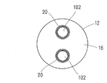
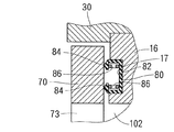
入口ハウジング12は、筒部14および円板部16により漏斗状に形成されている。筒部14に通路302と連通する第1通路としてのラジエータ通路が形成されている。ラジエータ通路は二つに別れ、ハウジングの内周壁である円板部16を貫通して弁部材70側に開口している連通路102を形成している。図4に示すように、円板部16の弁部材70側に連通路102の開口周囲を囲むように環状の溝17が形成されている。図3に示す環状ゴム製のシール部材20は、焼き付けまたは接着等により図4に示す溝17に取り付けられている。冷却水流れに沿い、前記シール部材20の中央を貫通する中心軸を含むシール部材20の断面形状は、弁部材70と接触している短辺と溝17の底部に接触している長辺とが平行な等脚台形である。
【0015】
図1に示す駆動ハウジング30は円板状の弁部材70を回動可能に流体室110に収容している。流体室110は、連通孔73、連通孔77(図6参照)および流出通路124と連通している。駆動ハウジング30およびカバー32は、弁部材70を回動駆動する駆動装置としてのステップモータ40を収容している。ステップモータ40は、シャフト42の外周に周方向に交互に異なる磁極を形成する永久磁石44を設置している。永久磁石44の外周に、コイル46が周方向に複数設置されている。コイル46に通電する方向を制御することによりコイル46の極性を交互に変化させ、シャフト42を所定角度回動させる。
【0016】
シャフト42の端部に駆動ギア50が取り付けられている。駆動ハウジング30に回動可能に取り付けられているシャフト54に、軸方向両端部にギア歯58、60を有する駆動ギア56が取り付けられている。ギア歯58は駆動ギア50のギア歯52と係合し、ギア歯60は駆動ギア64のギア歯66と係合する。ギア歯60のギア径はギア歯58のギア径よりも小さい。駆動ギア64を取り付けているシャフト62は弁部材70とともに回動する。シャフト62を軸受けするベアリング68は、図5に示すように内周側よりも外周側が円板部16側にずれるように組付けられている。これにより、シャフト62が円板部16から離れる方向に移動することを防止する。
【0017】
図1に示すように、駆動ハウジング30には、バイパス通路304と連通する第2通路であるバイパス通路120、通路310と連通するヒータ通路122、ならびに通路306と連通する第3通路である流出通路124が形成されている。
【0018】
弁部材70は、入口ハウジング12の円板部16と向き合う摺動部としての円板部72と、円板部72の周方向の一部において円板部72の外周縁からシャフト62に沿って入口ハウジング12と反対側に突出する閉塞部74とを有している。図6に示すように、連通路として2個の円形の連通孔73が回転中心を挟み180°反対側に円板部72に形成されている。連通孔73はラジエータ通路と流体室110とを連通可能である。閉塞部74は円弧状に形成されており、バイパス閉塞部76とヒータ閉塞部78とを有している。ヒータ閉塞部78はバイパス閉塞部76からさらにシャフト62に沿って入口ハウジング12と反対側に突出している。バイパス閉塞部76はバイパス通路120だけを閉塞可能であり、ヒータ閉塞部78はバイパス通路120およびヒータ通路122の両方を閉塞可能である。バイパス閉塞部76にはバイパス通路120と流体室110とを連通可能な連通孔77が形成されている。
【0019】
次に、流量制御弁装置10の製造工程について説明する。
(1)シャフト62と弁部材70とを組み付ける。
(2)駆動ハウジング30にベアリング68を取り付ける。
(3)弁部材70を組み付けたシャフト62をベアリング68で軸受けする。
(4)シャフト62の弁部材70と反対側の端部に駆動ギア64を取り付ける。さらに、駆動ギア56を取り付けたシャフト54をギア歯60がギア歯66と係合するように駆動ハウジング30に取り付ける。
(5)シャフト42に駆動ギア50を取り付けたステップモータ40をギア歯52がギア歯58に係合するように組み付ける。
【0020】
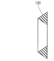
(6)シール部材20の母材130を図7に示す。母材130の中央を貫通する中心軸を含む断面形状は三角形である。この三角形の断面の一辺を溝17の底部に接触させ、焼き付けまたは接着等により溝17に母材130を取り付ける。母材130は半加硫状態のゴムであり、塑性変形する。母材130のゴム材として、EPDM(エチレンプロピレンゴム)、NBR(ニトリルゴム)、フッ素系ゴム等を用いる。
【0021】
(7)工程(5)で組み付けた構造体と、工程(6)で組み付けた構造体とを、溝17に接触している一辺に向き合う母材130の頂点が弁部材70と接触するように弁部材70を組み付ける。母材130は、弁部材70の円板部72の摺動面に合わせ図4に示すように中心軸を含む断面が等脚台形状に塑性変形する。
(8)工程(7)で組み付けた構造体を約100℃で加熱し、母材130を加硫させる。加熱により加硫された母材130は弾性を有するシール部材20となる。
【0022】
シール部材20は円板部72の摺動面の形状に合わせて塑性変形し加硫されているので、シール部材20は弁部材70の円板部72と摺動するが円板部72に押し付けられていない。したがって、シール部材20と弁部材70との摺動抵抗は小さい。
【0023】
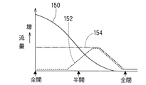
次に、流量制御弁装置10の作動について図8および図9に基づき説明する。図9において、実線150はラジエータ202からラジエータ通路、連通路102、連通孔73を通り流体室110に流入する冷却水の流量を示している。点線152は、バイパス通路120から流体室110に流入する冷却水の流量を示している。一点鎖線154は、ヒータ通路122から流体室110に流入する冷却水の流量を示している。流体室110から流出通路124を通りエンジン200に供給される冷却水の流量は、実線150、点線152および一点鎖線154が示す流量の合計である。
【0024】
(1)弁部材70が図8の(A)に示す位置にあるとき、連通路102と連通孔73とは同心上にあり、連通路102と流体室110とは連通孔73を介し全開状態で連通している。バイパス通路120と流体室110との連通は、バイパス閉塞部76により遮断されている。、ヒータ通路122は流体室110と連通している。このときの冷却水の流量は図9に示す全開状態である。
【0025】
(2)弁部材70が図8の(A)に示す位置から図8の(B)に示す位置に回転すると、連通孔73を介し連通路102と流体室110とが連通する面積は徐々に小さくなる。したがって、ラジエータ202から連通路102、連通孔73を通り流体室110に流入する冷却水の流量は減少する。一方、バイパス閉塞部76の連通孔77を介しバイパス通路120と流体室110とが連通するので、バイパス通路120から流体室110に流入する冷却水の流量は増加する。ヒータ通路122は開放されているので、ヒータ通路122から流体室110に流入する冷却水の流量は一定である。
【0026】
(3)弁部材70が図8の(B)に示す位置から図8の(C)に示す位置に回転すると、連通孔73を介し連通路102と流体室110とが連通する面積はさらに小さくなる。したがって、ラジエータ202から連通路102、連通孔73を通り流体室110に流入する冷却水の流量は減少し、図8の(C)に示す全閉状態では0になる。バイパス閉塞部76の連通孔77を介しバイパス通路120と流体室110とが連通する面積はピークに達したあと減少する。ヒータ通路122と流体室110との連通面積はヒータ閉塞部78により徐々に減少する。したがって、ヒータ通路122から流体室110の流入する冷却水の流量は減少する。
【0027】
このように、弁部材70の回動角度を調節することにより、エンジン200に供給する冷却水の流量および温度を調整する。
例えば、弁部材70の回動位置を図8の(C)に示す全閉位置に近づけることにより、エンジン200を循環する冷却水の流量を減少し、エンジン始動時にエンジンを早期に暖機運転する。
【0028】
エンジン200の冷却性を高めるためには、弁部材70の回動位置を図8の(A)に示す全開位置に近づける。ラジエータ202で冷却されエンジン200に供給される冷却水の流量が増加するので、エンジン200をより冷却することができる。
【0029】
第1実施例では、半加硫状態のシール部材20の母材130と弁部材70とを組み付けることにより、弁部材70の摺動面に合わせて母材130を塑性変形させ、その後に母材130を加熱して加硫しシール部材20に弾性をもたせている。シール部材20が弁部材70に押し付けられていないので、シール部材20と弁部材70との摺動抵抗が小さい。小さなトルクで弁部材70を回動駆動できるので、ステップモータ40を小型化できる。また、シール部材20が弁部材70の摺動面に沿って摺動するので、シール部材20と弁部材70との間のシールを確保できる。
【0030】
また、塑性変形前の断面三角形状の母材130の一辺を溝17に取り付け、この一辺と向き合う頂点を弁部材70に接触させ弁部材70を組み付けることにより母材130を塑性変形させる。したがって、塑性変形後の母材130が弁部材70と接触している面積を、溝17と接触している面積よりも小さくすることが容易である。
【0031】
塑性変形後の母材130の中心軸を含む断面形状は、弁部材70側を短辺とし、溝17側を短辺と平行であり短辺よりも長い長辺とする等脚台形である。弁部材70と摺動するシール部材20の面積が小さいので、シール部材20と弁部材70との摺動抵抗が小さくなる。また、溝17と接触するシール部材20の面積が大きいので、溝17に安定してシール部材20を取り付けることができる。さらに、弁部材70がいずれの方向に回動しても、シール部材70が一方に傾くことを防止できる。
【0032】
(第2実施例、第3実施例)
本発明の第2実施例によるシール部材を図10および図11に、第3実施例を図12に示す。
第2実施例のシール部材80は環状に形成されており、平板な底部82と、底部82の外周縁および内周縁から弁部材70側に延びる環状のリップ84とを有している。シール部材80の中心軸を含む断面において、シール部材80は弁部材70側に開口している。シール部材80は溝17に焼き付けられておらず嵌合している。
【0033】
付勢部材としてのコイルスプリング86は底部82と内周側および外周側のリップ84とが形成する空間に収容されている。コイルスプリング86は溝17に底部82を付勢しているとともに、弁部材70にリップ84を付勢している。コイルスプリング86が弁部材70および溝17に向けシール部材80を付勢しているので、溝17にシール部材80を嵌合するだけでシール部材80を組み付けることができる。
【0034】
また、コイルスプリング86が弾性変形しやすいリップ84を弁部材70に向け付勢しているので、小さな付勢力で弁部材70にリップ84を押し付けることができる。コイルスプリング86の付勢力を調整することにより、シール部材80と弁部材70との摺動抵抗を極力小さくしつつ、弁部材70とシール部材80との間のシールを確保できる。
図12に示す第3実施例では、第2実施例のコイルスプリング86に代え、付勢部材として環状の板ばね88を用いている。
【0035】
(第4実施例)
本発明の第4実施例によるシール部材を図13に示す。
シール部材90は環状に形成されており、平板な底部92と、底部92の外周縁および内周縁から弁部材70側に延びる環状のリップ96とを有している。底部92の外壁に溝17に向けて突出する環状突部94が形成されている。シール部材90の中心軸を含む断面において、シール部材90は弁部材70側に開口している。シール部材90は溝17に焼き付けられておらず嵌合している。
【0036】
コイルスプリング86は底部92と内周側および外周側のリップ96とが形成する空間に収容されている。コイルスプリング86は溝17に環状突部94を付勢しているとともに、弁部材70にリップ96を付勢している。コイルスプリング86がシール部材90を弁部材70および溝17に向け付勢しているので、溝17にシール部材90を嵌合するだけでシール部材90を組み付けることができる。
【0037】
また、環状突部94が溝17と接触することによりシール部材90が入口ハウジング12と接触する面積が小さくなる。シール部材90が入口ハウジング12に単位面積当たり押し付けられる力が大きくなるので、コイルスプリング86の付勢力が小さくても、シール部材90と入口ハウジング12との間から冷却水が漏れることを防止できる。
【図面の簡単な説明】
【図1】本発明の第1実施例の製造方法により製造した流量制御弁装置を示す断面図である。
【図2】第1実施例の流量制御弁装置を用いた冷却システムを示す構成図である。
【図3】第1実施例のシール部材を示す図1のIII 方向矢視図である。
【図4】第1実施例のシール部材を示す拡大断面図である。
【図5】第1実施例による弁部材のシャフトを軸受けするベアリングの取り付け状態を示す説明図である。
【図6】(A)は第1実施例の弁部材を示す図1のVI方向矢視図であり、(B)は(A)のB方向矢視図である。
【図7】塑性変形前のシール部材の母材を示す断面図である。
【図8】弁部材の回動による通路の連通状態を示す説明図である。
【図9】弁部材の回動にともない変化するラジエータから流入する冷却水量、バイパス通路から流入する冷却水量、ならびにヒータ通路から流入する冷却水量を示す特性図である。
【図10】第2実施例のシール部材を示す断面図である。
【図11】第2実施例のシール部材の取り付け状態を示す断面図である。
【図12】第3実施例のシール部材を示す断面図である。
【図13】第4実施例のシール部材を示す断面図である。
【符号の説明】
10 流量制御弁装置
12 入口ハウジング(ハウジング)
20、80、90 シール部材
30 駆動ハウジング(ハウジング)
32 カバー(ハウジング)
40 ステップモータ(駆動装置)
70 弁部材
72 円板部(摺動部)
73 連通孔(連通路)
86 コイルスプリング(付勢部材)
88 板ばね(付勢部材)
94 環状突部
100 ラジエータ通路(第1通路)
102 連通路(第1通路)
110 流体室
120 バイパス通路(第2通路)
122 ヒータ通路
124 流出通路(第3通路)[0001]
BACKGROUND OF THE INVENTION
The present invention is an internal combustion engine (hereinafter, "internal combustion engine" is called engine) it relates to a method for manufacturing a Ru-flow amount control valve apparatus using the cooling system for cooling a.
[0002]
[Prior art]
2. Description of the Related Art A cooling system that supplies cooling water as a cooling medium cooled by a radiator to an engine to cool the engine uses a thermostat to control the temperature of the cooling water. When the temperature of the cooling water is equal to or lower than a predetermined temperature, a cooling medium circulation circuit is configured to return the cooling water to the engine without passing through the radiator without flowing through the radiator by operating the thermostat. Thus, when a thermostat is used as a flow control valve device that detects the temperature of the cooling water and controls the flow rate of the cooling water, the flow control valve device can be realized at low cost.
However, since the operation of the thermostat is defined by the temperature characteristics of the temperature sensing member that detects the temperature of the cooling water, the flow rate of the cooling water cannot be controlled with high accuracy according to the engine operating state.
[0003]
In order to solve the above-described problem, a flow control valve device is known that controls the rotation angle of the valve member in accordance with the operating state of the engine and controls the flow rate of the cooling water with high accuracy by the rotation angle of the valve member. Yes. Such a flow control valve device has a radiator passage through which cooling water flows from the radiator, a bypass passage through which cooling water branched from a flow from the engine toward the radiator, and an outflow passage through which cooling water is supplied to the engine. And what drives a valve member rotationally with drive devices, such as a step motor, is known. The rotation angle of the valve member is performed by controlling energization to the step motor according to the operating state of the engine.
An annular rubber seal member is provided around the opening of the radiator passage. When the valve member rotates, the seal member slides with the valve member, and the space between the valve member and the seal member is sealed.
[0004]
[Problems to be solved by the invention]
However, if the rubber seal member is elastically deformed and pressed against the valve member with a large force to ensure a seal between the valve member and the seal member, the sliding resistance between the valve member and the seal member increases, and the valve member A large torque is required to rotate the.
[0005]
In order to reduce the force of the seal member that presses against the valve member and to secure a seal between the valve member and the seal member, it is necessary to process the seal member with high precision by polishing or the like, which increases the manufacturing cost. There is a problem of doing.
An object of the present invention is to provide a manufacturing method of processing easy that flow control valve apparatus having a sliding resistance is small sealing member and the valve member.
[0006]
[Means for Solving the Problems]
According to the manufacturing method of the flow control valve device according to
Since the base material of the sealing member is plastically deformed in accordance with the sliding surface of the valve member in the semi-vulcanized state to define the shape of the sealing member, the processing of the sealing member is easy. Furthermore, since the sliding resistance between the seal member and the valve member is small, the valve member can be driven to rotate with a small torque.
[0007]
According to the manufacturing method of the flow control valve device according to claim 2 of the present invention, the area where the base material after plastic deformation is in contact with the valve member is smaller than the area where the base material is in contact with the inner peripheral wall of the housing. Since the sliding resistance between the seal member obtained by heating and vulcanizing the plastically deformed base material and the valve member becomes small, the valve member can be driven to rotate with a small torque. Further, since the area of the seal member that contacts the inner peripheral wall of the housing is large, the seal member can be stably attached to the housing.
[0008]
According to the manufacturing method of the flow control valve device according to claim 3 of the present invention, the cross-sectional shape including the central axis passing through the center of the base material before plastic deformation is a triangular shape, and one side of the triangular cross-section is formed on the housing. The base material is plastically deformed by being attached to the inner peripheral wall and contacting the valve member with a vertex facing one side attached to the housing and assembling the valve member. It is easy to make the area in which the base material after plastic deformation is in contact with the valve member smaller than the area in contact with the inner peripheral wall of the housing.
[0009]
According to the method for manufacturing a flow control valve device according to claim 4 of the present invention, since the cross-sectional shape of the seal member after plastic deformation is an isosceles trapezoid, the seal member no matter which direction the valve member rotates Is prevented from tilting in one direction of rotation .
[0012]
DETAILED DESCRIPTION OF THE INVENTION
Hereinafter, a plurality of examples showing embodiments of the present invention will be described with reference to the drawings.
(First embodiment)
FIG. 2 shows a cooling system using the flow control valve device manufactured by the manufacturing method according to the first embodiment of the present invention.
Cooling water that is a cooling medium is supplied to the water jacket of the
[0013]
(1) The
(2) Passes through the
(3) The
The cooling water whose rate of flow from the three systems is adjusted by the flow
[0014]
As shown in FIG. 1, the flow
The
[0015]
The
[0016]
A drive gear 50 is attached to the end of the
[0017]
As shown in FIG. 1, the
[0018]
The
[0019]
Next, the manufacturing process of the flow
(1) The
(2) A
(3) The
(4) A
(5) The
[0020]
(6) The
[0021]
(7) The structure assembled in step (5) and the structure assembled in step (6) so that the apex of
(8) The structure assembled in the step (7) is heated at about 100 ° C. to vulcanize the
[0022]
Since the
[0023]
Next, the operation of the flow
[0024]
(1) When the
[0025]
(2) When the
[0026]
(3) When the
[0027]
Thus, the flow rate and temperature of the cooling water supplied to the
For example, by bringing the rotation position of the
[0028]
In order to improve the cooling performance of the
[0029]
In the first embodiment, the
[0030]
In addition, one side of the
[0031]
The cross-sectional shape including the central axis of the
[0032]
(Second Example, Third Example)
A seal member according to a second embodiment of the present invention is shown in FIGS. 10 and 11, and a third embodiment is shown in FIG.
The
[0033]
The
[0034]
Further, since the
In the third embodiment shown in FIG. 12, instead of the
[0035]
(Fourth embodiment)
A seal member according to a fourth embodiment of the present invention is shown in FIG.
The
[0036]
The
[0037]
Further, when the
[Brief description of the drawings]
FIG. 1 is a cross-sectional view showing a flow control valve device manufactured by a manufacturing method according to a first embodiment of the present invention.
FIG. 2 is a block diagram showing a cooling system using the flow control valve device of the first embodiment.
FIG. 3 is a view in the direction of the arrow III in FIG. 1 showing the seal member of the first embodiment.
FIG. 4 is an enlarged sectional view showing a seal member of the first embodiment.
FIG. 5 is an explanatory view showing a mounting state of a bearing for bearing the shaft of the valve member according to the first embodiment.
6A is a view in the direction of the arrow VI in FIG. 1 showing the valve member of the first embodiment, and FIG. 6B is a view in the direction of the arrow B in FIG.
FIG. 7 is a cross-sectional view showing a base material of a seal member before plastic deformation.
FIG. 8 is an explanatory view showing a communication state of the passage by the rotation of the valve member.
FIG. 9 is a characteristic diagram showing the amount of cooling water flowing from the radiator, the amount of cooling water flowing from the bypass passage, and the amount of cooling water flowing from the heater passage, which change with the rotation of the valve member.
FIG. 10 is a cross-sectional view showing a seal member of a second embodiment.
FIG. 11 is a cross-sectional view showing a mounting state of the seal member of the second embodiment.
FIG. 12 is a cross-sectional view showing a seal member of a third embodiment.
FIG. 13 is a cross-sectional view showing a seal member of a fourth embodiment.
[Explanation of symbols]
10 Flow
20, 80, 90
32 Cover (housing)
40 Step motor (drive device)
70
73 Communication hole (communication passage)
86 Coil spring (biasing member)
88 Leaf spring (biasing member)
94
102 Communication passage (first passage)
110
122
Claims (4)
前記ハウジングの内周壁に開口している前記第1通路の開口を囲んで前記ハウジングの内周壁に設置されている環状ゴム製のシール部材と、
前記ハウジング内に回動可能に収容され、回動することにより前記シール部材と摺動する摺動部を有し、前記第1通路および前記第2通路から前記ハウジング内に流入し前記第3通路から流出する冷却媒体の流量を回動角度に応じて制御する弁部材と、
前記弁部材を回動駆動する駆動装置とを備える流量制御弁装置の製造方法であって、
前記第1通路の開口周囲の前記ハウジングの内周壁に半加硫の状態で前記シール部材の母材を取り付け、前記母材に前記弁部材を接触させ前記弁部材を組み付けることにより前記母材を塑性変形させ、前記母材を加熱し加硫することを特徴とする流量制御弁装置の製造方法。A housing having a first passage through which a cooling medium flows from a radiator, a second passage through which a cooling medium branched from a flow from the internal combustion engine toward the radiator, and a third passage for supplying the cooling medium to the internal combustion engine;
An annular rubber sealing member installed on the inner peripheral wall of the housing surrounding the opening of the first passage opening in the inner peripheral wall of the housing;
The housing is rotatably accommodated in the housing, and has a sliding portion that slides with the seal member by rotating. The third passage flows into the housing from the first passage and the second passage. A valve member for controlling the flow rate of the cooling medium flowing out from the valve according to the rotation angle;
A method for manufacturing a flow control valve device comprising a drive device for rotationally driving the valve member,
The base material of the seal member is attached to the inner peripheral wall of the housing around the opening of the first passage in a semi-vulcanized state, the valve member is brought into contact with the base material, and the valve member is assembled to attach the base material. A method of manufacturing a flow control valve device, wherein the base material is heated and vulcanized by plastic deformation.
Priority Applications (1)
| Application Number | Priority Date | Filing Date | Title |
|---|---|---|---|
| JP2002147459A JP4096355B2 (en) | 2002-05-22 | 2002-05-22 | Manufacturing method of flow control valve device |
Applications Claiming Priority (1)
| Application Number | Priority Date | Filing Date | Title |
|---|---|---|---|
| JP2002147459A JP4096355B2 (en) | 2002-05-22 | 2002-05-22 | Manufacturing method of flow control valve device |
Publications (2)
| Publication Number | Publication Date |
|---|---|
| JP2003336753A JP2003336753A (en) | 2003-11-28 |
| JP4096355B2 true JP4096355B2 (en) | 2008-06-04 |
Family
ID=29706016
Family Applications (1)
| Application Number | Title | Priority Date | Filing Date |
|---|---|---|---|
| JP2002147459A Expired - Fee Related JP4096355B2 (en) | 2002-05-22 | 2002-05-22 | Manufacturing method of flow control valve device |
Country Status (1)
| Country | Link |
|---|---|
| JP (1) | JP4096355B2 (en) |
Cited By (1)
| Publication number | Priority date | Publication date | Assignee | Title |
|---|---|---|---|---|
| CN105074301A (en) * | 2013-03-21 | 2015-11-18 | 日立汽车系统株式会社 | Flow rate-controlling valve |
Families Citing this family (5)
| Publication number | Priority date | Publication date | Assignee | Title |
|---|---|---|---|---|
| JP4650274B2 (en) * | 2006-01-12 | 2011-03-16 | 株式会社デンソー | Air conditioner |
| JP4784449B2 (en) * | 2006-01-12 | 2011-10-05 | 株式会社デンソー | Seal structure of rotating part and air conditioner using the same |
| JP4529907B2 (en) * | 2006-01-12 | 2010-08-25 | 株式会社デンソー | Air conditioner |
| JP2010101273A (en) * | 2008-10-24 | 2010-05-06 | Denso Corp | Exhaust gas cooling system and method for manufacturing the same |
| KR101802763B1 (en) | 2015-12-22 | 2017-11-29 | 엘지전자 주식회사 | Gas furnace for heating an indoor space |
-
2002
- 2002-05-22 JP JP2002147459A patent/JP4096355B2/en not_active Expired - Fee Related
Cited By (1)
| Publication number | Priority date | Publication date | Assignee | Title |
|---|---|---|---|---|
| CN105074301A (en) * | 2013-03-21 | 2015-11-18 | 日立汽车系统株式会社 | Flow rate-controlling valve |
Also Published As
| Publication number | Publication date |
|---|---|
| JP2003336753A (en) | 2003-11-28 |
Similar Documents
| Publication | Publication Date | Title |
|---|---|---|
| JP4614842B2 (en) | Clutchless viscous fan drive device including a main body that supports a sealing member and an input member that functions as a cover | |
| WO2016092935A1 (en) | Refrigerant control valve device | |
| KR102252705B1 (en) | Valve device | |
| US20150075453A1 (en) | Rotary valve | |
| US8701852B2 (en) | Viscous fan drive systems having fill and scavenge control | |
| US11098808B2 (en) | Control valve | |
| CA2620924A1 (en) | Automotive coolant pump apparatus | |
| JP5916901B2 (en) | Mechanical coolant pump | |
| WO1999057428A1 (en) | Device for mounting exhaust gas reflux valve | |
| JPH0366536B2 (en) | ||
| JP4096355B2 (en) | Manufacturing method of flow control valve device | |
| CA2250160C (en) | Coolant pump for automotive use | |
| US20060243817A1 (en) | Viscous fan drive with a fluid control valve | |
| US6499963B2 (en) | Coolant pump for automotive use | |
| CA2435158C (en) | Proportional valve | |
| US20140209180A1 (en) | Viscous fan drive systems having fill and scavenge control | |
| JP2018204615A (en) | Flow control valve | |
| JP2002106347A (en) | Cooling water temperature control device of internal combustion engine | |
| JP5034949B2 (en) | Thermostat device and associated method | |
| KR20210120547A (en) | Flow control valve | |
| JP4059055B2 (en) | Cooling liquid injection method and flow control valve used for the injection method | |
| WO2020184032A1 (en) | Fluid control valve | |
| WO2023167141A1 (en) | Valve device | |
| JPH051033U (en) | Fluid fitting | |
| JP2019085941A (en) | Valve device |
Legal Events
| Date | Code | Title | Description |
|---|---|---|---|
| A621 | Written request for application examination |
Free format text: JAPANESE INTERMEDIATE CODE: A621 Effective date: 20041015 |
|
| A977 | Report on retrieval |
Free format text: JAPANESE INTERMEDIATE CODE: A971007 Effective date: 20070607 |
|
| A131 | Notification of reasons for refusal |
Free format text: JAPANESE INTERMEDIATE CODE: A131 Effective date: 20070803 |
|
| A521 | Written amendment |
Free format text: JAPANESE INTERMEDIATE CODE: A523 Effective date: 20070926 |
|
| TRDD | Decision of grant or rejection written | ||
| A01 | Written decision to grant a patent or to grant a registration (utility model) |
Free format text: JAPANESE INTERMEDIATE CODE: A01 Effective date: 20080218 |
|
| A61 | First payment of annual fees (during grant procedure) |
Free format text: JAPANESE INTERMEDIATE CODE: A61 Effective date: 20080302 |
|
| R150 | Certificate of patent or registration of utility model |
Free format text: JAPANESE INTERMEDIATE CODE: R150 |
|
| FPAY | Renewal fee payment (event date is renewal date of database) |
Free format text: PAYMENT UNTIL: 20110321 Year of fee payment: 3 |
|
| FPAY | Renewal fee payment (event date is renewal date of database) |
Free format text: PAYMENT UNTIL: 20120321 Year of fee payment: 4 |
|
| FPAY | Renewal fee payment (event date is renewal date of database) |
Free format text: PAYMENT UNTIL: 20120321 Year of fee payment: 4 |
|
| FPAY | Renewal fee payment (event date is renewal date of database) |
Free format text: PAYMENT UNTIL: 20130321 Year of fee payment: 5 |
|
| FPAY | Renewal fee payment (event date is renewal date of database) |
Free format text: PAYMENT UNTIL: 20140321 Year of fee payment: 6 |
|
| LAPS | Cancellation because of no payment of annual fees |