JP4094818B2 - Fasteners, fastener systems, and tools for use in fastener systems - Google Patents
Fasteners, fastener systems, and tools for use in fastener systems Download PDFInfo
- Publication number
- JP4094818B2 JP4094818B2 JP2000613615A JP2000613615A JP4094818B2 JP 4094818 B2 JP4094818 B2 JP 4094818B2 JP 2000613615 A JP2000613615 A JP 2000613615A JP 2000613615 A JP2000613615 A JP 2000613615A JP 4094818 B2 JP4094818 B2 JP 4094818B2
- Authority
- JP
- Japan
- Prior art keywords
- pin
- recess
- tool
- spline
- nut
- Prior art date
- Legal status (The legal status is an assumption and is not a legal conclusion. Google has not performed a legal analysis and makes no representation as to the accuracy of the status listed.)
- Expired - Lifetime
Links
- 230000000295 complement effect Effects 0.000 claims 1
- 230000001747 exhibiting effect Effects 0.000 claims 1
- 239000000463 material Substances 0.000 description 18
- 238000013461 design Methods 0.000 description 4
- 238000009434 installation Methods 0.000 description 3
- 230000013011 mating Effects 0.000 description 3
- 230000006835 compression Effects 0.000 description 2
- 238000007906 compression Methods 0.000 description 2
- 238000010276 construction Methods 0.000 description 1
- 238000007373 indentation Methods 0.000 description 1
- 238000003780 insertion Methods 0.000 description 1
- 230000037431 insertion Effects 0.000 description 1
- 238000012986 modification Methods 0.000 description 1
- 230000004048 modification Effects 0.000 description 1
- 238000012545 processing Methods 0.000 description 1
- 239000003566 sealing material Substances 0.000 description 1
- 239000007787 solid Substances 0.000 description 1
Images


Classifications
-
- F—MECHANICAL ENGINEERING; LIGHTING; HEATING; WEAPONS; BLASTING
- F16—ENGINEERING ELEMENTS AND UNITS; GENERAL MEASURES FOR PRODUCING AND MAINTAINING EFFECTIVE FUNCTIONING OF MACHINES OR INSTALLATIONS; THERMAL INSULATION IN GENERAL
- F16B—DEVICES FOR FASTENING OR SECURING CONSTRUCTIONAL ELEMENTS OR MACHINE PARTS TOGETHER, e.g. NAILS, BOLTS, CIRCLIPS, CLAMPS, CLIPS OR WEDGES; JOINTS OR JOINTING
- F16B23/00—Specially shaped nuts or heads of bolts or screws for rotations by a tool
- F16B23/0007—Specially shaped nuts or heads of bolts or screws for rotations by a tool characterised by the shape of the recess or the protrusion engaging the tool
- F16B23/003—Specially shaped nuts or heads of bolts or screws for rotations by a tool characterised by the shape of the recess or the protrusion engaging the tool star-shaped or multi-lobular, e.g. Torx-type, twelve-point star
-
- B—PERFORMING OPERATIONS; TRANSPORTING
- B25—HAND TOOLS; PORTABLE POWER-DRIVEN TOOLS; MANIPULATORS
- B25B—TOOLS OR BENCH DEVICES NOT OTHERWISE PROVIDED FOR, FOR FASTENING, CONNECTING, DISENGAGING OR HOLDING
- B25B15/00—Screwdrivers
- B25B15/001—Screwdrivers characterised by material or shape of the tool bit
- B25B15/004—Screwdrivers characterised by material or shape of the tool bit characterised by cross-section
- B25B15/005—Screwdrivers characterised by material or shape of the tool bit characterised by cross-section with cross- or star-shaped cross-section
-
- F—MECHANICAL ENGINEERING; LIGHTING; HEATING; WEAPONS; BLASTING
- F16—ENGINEERING ELEMENTS AND UNITS; GENERAL MEASURES FOR PRODUCING AND MAINTAINING EFFECTIVE FUNCTIONING OF MACHINES OR INSTALLATIONS; THERMAL INSULATION IN GENERAL
- F16B—DEVICES FOR FASTENING OR SECURING CONSTRUCTIONAL ELEMENTS OR MACHINE PARTS TOGETHER, e.g. NAILS, BOLTS, CIRCLIPS, CLAMPS, CLIPS OR WEDGES; JOINTS OR JOINTING
- F16B35/00—Screw-bolts; Stay-bolts; Screw-threaded studs; Screws; Set screws
- F16B35/04—Screw-bolts; Stay-bolts; Screw-threaded studs; Screws; Set screws with specially-shaped head or shaft in order to fix the bolt on or in an object
- F16B35/041—Specially-shaped shafts
- F16B35/044—Specially-shaped ends
- F16B35/045—Specially-shaped ends for retention or rotation by a tool
Description
【0001】
発明の分野
本発明は、大別して、締結具システムに関し、詳細には、締結具にナットを取り付ける際に嵌合相手の工具を受容するためのスプライン駆動凹部を有したネジ締結具を備える締結具システムに関する。
【0002】
発明の背景
螺刻されてネジ山部が設けられた締結具、すなわちネジ締結具は、典型的にはナットとボルトとからなる。ナットはボルトの雄ねじ(外ネジ)にネジ留めされる雌ネジ(内ネジ)を有している。ナット及び/又はボルト上のレンチを作用させる表面は、締結具と単数又は複数の被加工物とを相互に堅く結合させるレンチを受容する。締結具は複数の被加工物を相互に留めて、被加工物の一方の側に位置するナットと反対側に位置するボルトの頭部との間で圧縮係合による接合部を形成する。
【0003】
米国特許第4260005号明細書は戻り止めナットを有した特殊なタイプのネジ締結具を記載しており、戻り止めナットは、概略三角形状又はΔ形状のソケットを有したドライバを受容するために外側ローブ(外側突出部)を用い、協働するピンにナットを締め付ける。本発明の理解のために必要となるこの特許の教示内容はこの参照により本願と一体のものとされる。ナットは、ピンに沿って長手方向に延びる複数の窪み又は溝を有したピンと共に使用されることが好ましい。形成された接合部に予め定められた軸線方向荷重が発生すると、ローブが塑性変形を起こし、ドライバはもはやナットを回転させることができなくなる。ローブの変形により、半径方向内側に位置する材料がローブから協働するピンの溝内に移動し、機械的なネジロックを生成させる。ネジロックは、材料がピンの溝内にピン溝と交差するように変形することにより生じる。
【0004】
ナットにトルクを作用させてピンに取り付けている間、前縁から回転に抗して保持され得る締結具を提供することが有利となる多数の応用例が存在する。例えば、航空宇宙産業によく見られるように、ボルトの頭部に手を伸ばせないことが好都合である又はボルトの頭部がレンチの使用の目的では恐らくは全く手を伸ばせないようにする「隠し(ブラインド)」ボルト応用例に対する多数の要求が存在する。これらの応用例のためには、多くの場合、保持ビット又は保持工具がドライバに設けられる。保持ビットは、ピンの螺刻された端部の凹部に係合して、ドライバによるナットの取り付けを容易にさせる。ビットは静止したままであるので、ドライバが回転してナットにトルクを作用させている間、回転に抗してピンを保持する。米国特許第4583483号及び同第5044225号の明細書は、締結具の迅速な取り付けのために開発された電動工具と共にこのようなビット又は工具を使用することを記載している。
【0005】
一般に、ボルトの螺刻された端部には、対応する六角形状ビットを受容するための六角形状凹部が設けられている。しかしながら、既存の六角形状ビットは、或る湿潤密封材応用例においてボルトを取り付ける際に使用されたとき、許容することができない失敗率を経験してきた。これらの応用例では、多くの場合、密封材が、ボルトの頭部を取り囲んでおり、ボルトと被加工物との間に存在している。結果として、ピンにナットを取り付けるために必要とされるトルクの全ては、ボルトの頭部と被加工物との間に通常存在する摩擦によって一部が吸収されるのではなく、ビットに直接的に伝達される。生じさせられた上述のトルクが六角形状ビットの強度を超えると、ナットの取り付けは不可能となる。
【0006】
この問題を解決する初期の試みは六角形状ビットの断面及び材料を変化させることを含んでいた。しかしながら、これらの試みは、六角形状凹部に対する半径方向の荷重のために、大部分が不成功となった。スプラインキー及びドライバは公知であり、多くの用途で使用されてきた。標準的なスプライン凹部及びレンチ締め工具は、締結具に関連して使用されるとき、締結具のスプライン(歯)をレンチ工具によって剪断変形させる結果を生じさせる。トルクは工具の嵌合相手のスプライン突出部から凹部のスプライン突出部へ伝達される。締結具を着座させた後、抵抗が生じたときに、付加的なトルクを作用させることにより、スプラインが形成されているソケットの剪断変形を生じさせ得る。剪断変形が生じるのは、標準的なスプライン設計によりレンチ駆動工具が通常は締結具の材料よりも強い材料から作成されるからである。標準的な構成形態によれば、レンチ締め工具のスプライン突出部表面積が締結具ソケットのスプライン突出部表面積よりも7.9%〜38.5%大きくなる結果となる。これが締結具ソケットよりも大きい剪断強度を有した工具と結合されることにより、許容できない失敗率を生じさせる。
【0007】
したがって、許容できない失敗を防止する締結具のためのスプライン駆動ソケット/工具構成に対する必要性が存在する。
【0008】
発明の要旨
したがって、本発明は、上述した従来技術の締結具システムに関して認められた不利点を最小にする改善された締結具システムを提供する。本発明による締結具システムは、通常、ピンに対してナットを回転させるトルクをナットに作用させるときに工具を受容するためにピンの螺刻された部分の端面に凹部を有した螺刻されたピンを含んでいる。現時点で好ましい実施形態では、凹部は、端面まで延びている新規に設計されたスプラインソケットを備えている。さらに、工具は、ピンに対してナットを回転させるトルクをナットに作用させるときにピンが回転することを防止するために工具が凹部に受容され得るように、凹部と対応するように構成された工具の少なくとも端部から延びる複数の嵌合相手のスプライン突出部を備えている。
【0009】
ピンは、ピンの螺刻された部分を横切って軸線方向に延びている複数の縦溝を含んでいることが好ましい。好ましくは、ナットは、少なくとも1つの軸線方向に延びる外側ローブを含んでいる。結果として、ピンに対してナットを回転させるトルクをナットに作用させるときに、ローブから半径方向に内方へ位置する材料の一部がピンの縦溝内に移動させられる。
【0010】
現時点で好ましい実施形態では、凹部は、凹部の周囲に延びる6つのスプライン突出部を備えたスプライン凹部である。工具は、ピンに対してナットを回転させるトルクをナットに作用させる際に凹部と係合するために、6つのスプライン突出部を備えたシャフトとして形成され、これらスプライン突出部は、シャフトの周囲に延びており、スプライン凹溝部と協働する寸法になっている。工具は、締結具のピンがナットの取り付けの際に回転することを防止させる。凹部及び工具の両方のスプライン突出部の幅及び剪断面積は、工具と凹部の両方に対するねじり荷重が等しくなるように形成されている。この設計の利点は、航空宇宙産業用締結具において特に重要となる凹部の強度が顕著に増大させられることである。この結果は、スプライン突出部の幅を工具上においてよりもソケットにおいて大きくなるように形成することによって達成される。凹部(相対的に低い強度の材料から作成されている)におけるスプライン突出部の幅を増加させることによって、剪断面積を増加させている。駆動工具(相対的に高い強度の材料から作成されている)のスプライン突出部の剪断面積は、ソケットの剪断面積と強度的に極めて均衡するように減少させられる。工具はソケットに必要以上の力を与えないので、最終的な結果はねじり性能において相当な増加となる。
【0011】
工具はさらに湾曲した小径部(又は内径部)を含むように設計された。典型的には、スプライン突出部を有したドライバであるスプラインドライバは機械加工された平坦な表面を備えた小径部を含んでいたが、この平坦な表面は除去された材料のために大切なねじり強度の損失を生じさせるのである。
本発明のこれら及び他の特徴及び利点は添付の図面と共に検討したときに以下の詳細な説明を参照することにより十分に理解されるであろう。
【0012】
発明の詳細な説明
ここで、図1から図3を参照すると、本発明による締結具システム10の現時点で好ましい実施形態が全体として示されている。締結具システムは、ボルト又はネジ山部が形成された螺刻されたピン12と、ナット14と、工具16とからなる締結具を含んでいる。ピン12及びナット14は共通の軸線を有している。被加工物からなる一対の板材20、22が締結具によって相互に留められる。締結具は板材を相互に留め、被加工物の一方側に位置するナット14と反対側に位置するピン12の頭部34との間に圧縮係合による接合部を形成する。筒状穴がナット14を貫通しており、この穴を形成するナットの内側表面(不図示)は螺刻されてネジ山が形成されている。ナット14は軸線方向に延びている複数の外側ローブ(突出部)15を有していることが好ましい。これらローブ15はその1つが示されており、ナット上に一体的に形成されている。ナット14の内側のネジ山部は螺刻されたピン12を受容するように構成されている。
【0013】
ピン12は、頭部34と反対側に、螺刻された部分36を有している。螺刻されている部分36は、ピン12のネジ山部を軸線方向に横切って延びている概略凹状の湾曲を有した複数の縦溝37を含んでいることが好ましい。ピンの螺刻された端部36の端面41は、ドライバ18(図1に仮想線で示されている)によってピンに対してナットを回転させるトルクをナットに作用させるときにピンの回転を防止するための工具16を受容する凹部39を含んでいる。締結具の着座の際に、ボルトの頭部とナットとの間に付与された軸線方向の荷重は予め定められたレベルまで増加する。そして、形成された接合部に予め定められた軸線方向荷重が生じると、ローブ15がピンの縦溝37内に塑性変形して、機械的なネジロックを生成させる。
【0014】
ナット上に設けられたローブの数に対するピン上に設けられた縦溝の数は、ローブのうちの少なくとも1つの材料の一部が縦溝の1つに進入して機械的なネジロックを生じさせ得るようになっていることが好ましい。現時点の好ましい実施形態では、5つの縦溝がピンに設けられ、3つのローブがナット上に設けられている。
【0015】
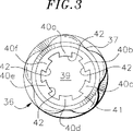
図2及び図3には、ピンがより詳細に示されている。ピン12は、被加工物の整列させられた穴32に受容されているシャンク30を含んでいる。シャンクの一方の端部36はナット14のネジ山部を受容するために螺刻されてネジ山部が形成されている。シャンクの他方の端部は頭部34を有し、この頭部34は、被加工物の露出している表面に圧迫を加え、ナットと協働して被加工物上に軸線方向の荷重を生じさせる。頭部は、任意に、レンチを作用させる表面を備えていないものが示されているが、六角形状頭又は皿頭のような他の従来のピン頭部を使用することが可能である。
ピン12の回転を防止するために、ピンの螺刻された端部36の端面41には、工具16を受容するための凹部39が設けられており、工具16は、ドライバが回転してナットにトルクを付与している間、ピンを静止状態に保持する。図2及び図3に示されている実施形態では、凹部39は凹部の周囲に等間隔で設けられたスプライン突出部40a〜40fを含んでいる。スプライン突出部は、ピンにおいて任意の適した手段によって形成されることができ、ピンの螺刻された端部の端面に機械加工されることが好ましい。好ましくは、凹部39は、全体が締結具の既存のピン長さ内に含まれており、ピンの螺刻された端部36の端面41から突出する材料を付加する必要がないようになっている。さらに、凹部の深さは、最小量の材料がピンの導入ネジ山域又は不完全なネジ山域から除去されるようになっていることが好ましい。例えば、2.286mm(0.090インチ)から2.413mm(0.095インチ)の間の凹部深さが許容可能である。
【0016】
本願でレンチソケットとも呼称されている凹部39は、「スプライン駆動」として公知となっているレンチソケットと類似の幾何形状を有したスプライン突出部40a〜40fを含んでいる。凹部39は、レンチ工具16の剪断強度を締結具材料の剪断強度と均衡させるために、大幅に改変されている。本発明のレンチソケット39は、ソケット及びレンチ工具の両方のねじり荷重が同等に極めて近いレベルとなるスプライン突出部の幅及び剪断面積を有するように設計されている。この設計は、特に締結具材料が低い強度を有しているときに、強度を増加させる。スプライン突出部40a〜40fの他の新規な特徴は、スプライン突出部の端部42がレンチ工具16の凸状に湾曲した小径部28(図4参照)を収容するように凹状に湾曲していることである。
【0017】
締結具の着座の際には、凹部39は工具16を受容し、これと係合し、ドライバ18によってナットにトルクが付与されたときにピン12の回転を防止する。工具16は、締結具の迅速な取り付けのために電動工具に取り付けられてもよく、手作業による締結具の取り付けの際に使用されてもよい。工具16の1つの実施形態が図1及び図4に示されている。工具は中実円柱シャフト24を備え、複数のスプライン突出部26がシャフトに沿って延びている。図4に最もよく示されているように、等間隔に離間配置された6つのスプライン突出部が、シャフトの長手方向軸線29と平行に、シャフトの周囲に設けられている。スプライン突出部は全て同じ寸法であることが好ましい。工具16のスプラインが凹部39の対応するスプライン内に受容される。ドライバによってナットにトルクが付与されると、工具及び凹部の対応する構成形態が互いと係合して、ピンが回転することを防止する。現時点で好ましい実施形態では、工具16は工具の前縁33上に傾斜端縁31を含んでおり、工具の凹部39への挿入を容易にさせている。工具は図1において電動ドライバと共に示されているが、手持ち形態で工具を手作業で使用することもできることは理解されるべきである。
【0018】
駆動スプライン突出部26は、レンチソケットの剪断面積と強度的に極めて均衡するように剪断面積を減少させるように計算されている。駆動工具はソケットに必要以上の力を与えることがないので、最終的な結果はねじり性能における大幅な増加となる。さらに、工具16の小径部28は湾曲した表面を有している。従前のスプライン駆動工具は平坦になった小径部を含んでおり、平坦な表面を形成するように材料が除去されていたので、大切なねじり強度の損失を引き起こしていた。湾曲した小径部を有することによって、付加的な材料により工具のねじり強度が増加させられている。対照的に、駆動工具のスプライン突出部の幅はソケットのスプライン突出部の幅よりも小さくなる。これら設計変更の全てが締結具のねじり値を改善させた。レンチソケットの改善されたねじり能力とねじり性能の最大化は、強度がより低い材料及び深さが最小のソケットにおいて使用されるときに特に重要となる。
【0019】
本願において記載された本発明の様々な改変及び変形は当業者にとって明らかである。例えば、凹部は、螺刻された端部に設けられるのが好ましいが、他のタイプの設置手順に合わせて締結具の頭部に設けられることもできる。さらに、凹部及びドライバを他のタイプの締結具のために使用することもできる。このような理由で、特許請求の範囲に記載の範囲内で、具体的に説明された以外のようにして本発明を実施することも可能であることは理解されよう。
【図面の簡単な説明】
【図1】 本発明の締結具システムの組立分解斜視図である。
【図2】 図1の締結具の前方部分断面図である。
【図3】 図2のピンの螺刻された端部の端面図である。
【図4】 図1のビットの斜視図である。[0001]
FIELD OF THE INVENTION The present invention relates generally to a fastener system, and in particular, a fastener comprising a screw fastener having a spline drive recess for receiving a mating tool when a nut is attached to the fastener. About the system.
[0002]
BACKGROUND OF THE INVENTION A fastener that is threaded and provided with a thread, i.e., a screw fastener, typically comprises a nut and a bolt. The nut has a female thread (inner thread) that is screwed to a male thread (outer thread) of the bolt. The surface on which the wrench on the nut and / or bolt acts receives a wrench that tightly couples the fastener and the workpiece or workpieces to each other. The fastener fastens a plurality of workpieces together to form a joint by compression engagement between a nut located on one side of the workpiece and a bolt head located on the opposite side.
[0003]
U.S. Pat. No. 4,226,0005 describes a special type of screw fastener with a detent nut, the detent nut being external for receiving a driver with a generally triangular or delta shaped socket. Use the lobe (outside protrusion) to tighten the nut on the cooperating pin. The teachings of this patent that are necessary for an understanding of the present invention are hereby incorporated by this reference. The nut is preferably used with a pin having a plurality of indentations or grooves extending longitudinally along the pin. When a predetermined axial load is generated at the formed joint, the lobe undergoes plastic deformation and the driver can no longer rotate the nut. Due to the deformation of the lobe, the radially inner material moves from the lobe into the cooperating pin groove, creating a mechanical screw lock. Screw lock is caused by the material deforming into the pin groove to intersect the pin groove.
[0004]
There are a number of applications where it would be advantageous to provide a fastener that can be held against rotation from the leading edge while torque is applied to the nut and attached to the pin. For example, as is often seen in the aerospace industry, it is convenient not to reach the bolt head, or to prevent the bolt head from reaching for the purpose of wrench use. There are a number of requirements for "blind" bolt applications. For these applications, a holding bit or holding tool is often provided in the driver. The retaining bit engages a recess in the threaded end of the pin to facilitate installation of the nut by the driver. Since the bit remains stationary, it holds the pin against rotation while the driver rotates and applies torque to the nut. U.S. Pat. Nos. 4,584,483 and 5,042,225 describe the use of such a bit or tool with a power tool developed for the quick attachment of fasteners.
[0005]
Generally, the bolted end of the bolt is provided with a hexagonal recess for receiving a corresponding hexagonal bit. However, existing hexagonal shaped bits have experienced unacceptable failure rates when used in installing bolts in certain wet seal applications. In these applications, in many cases, a sealing material surrounds the head of the bolt and exists between the bolt and the workpiece. As a result, all of the torque required to attach the nut to the pin is not directly absorbed by the friction normally present between the bolt head and the workpiece, but directly to the bit. Is transmitted to. If the generated torque exceeds the strength of the hexagonal bit, the nut cannot be attached.
[0006]
Early attempts to solve this problem included changing the cross-section and material of the hexagonal bit. However, these attempts have been largely unsuccessful due to radial loads on the hexagonal recesses. Spline keys and drivers are known and have been used in many applications. Standard spline recesses and wrench tools, when used in conjunction with fasteners, result in the splines (teeth) of the fastener being sheared by the wrench tool. Torque is transmitted to the splined projection of the recess from the spline projection of mating of the tool. After the fastener is seated, when resistance occurs, an additional torque can be applied to cause shear deformation of the socket in which the spline is formed. Shear deformation occurs because standard spline designs typically make the wrench drive tool from a stronger material than the fastener material. According to standard construction forms, resulting in spline protrusion surface area of the wrench tightening tool increases spline protrusion surface area by remote 7.9% ~38.5% fastener socket. This is combined with a tool having a greater shear strength than the fastener socket, resulting in an unacceptable failure rate.
[0007]
Accordingly, there is a need for a spline drive socket / tool configuration for a fastener that prevents unacceptable failures.
[0008]
SUMMARY OF THE INVENTION Accordingly, the present invention provides an improved fastener system that minimizes the disadvantages noted with respect to the prior art fastener systems described above. The fastener system according to the present invention is typically threaded with a recess in the end face of the threaded portion of the pin to receive the tool when the nut is subjected to torque that rotates the nut relative to the pin. Includes pins. In the presently preferred embodiment, the recess comprises a newly designed spline socket that extends to the end face. In addition, the tool was configured to correspond to the recess so that the tool could be received in the recess to prevent the pin from rotating when acting on the nut with a torque that rotates the nut relative to the pin. A plurality of mating spline protrusions extending from at least the end of the tool are provided.
[0009]
The pin preferably includes a plurality of longitudinal grooves extending axially across the threaded portion of the pin. Preferably, the nut includes at least one axially extending outer lobe. As a result, when a torque is applied to the nut that rotates the nut relative to the pin, a portion of the material located radially inward from the lobe is moved into the longitudinal groove of the pin.
[0010]
In the presently preferred embodiment, the recess is a spline recess with six spline protrusions extending around the recess. The tool is formed as a shaft with six spline protrusions to engage the recess when a torque is applied to the nut to rotate the nut relative to the pin, and these spline protrusions are placed around the shaft. It extends and is dimensioned to cooperate with the spline groove . The tool prevents the fastener pins from rotating during nut installation. The width and shear area of the spline protrusions of both the recess and the tool are formed so that the torsional loads on both the tool and the recess are equal. The advantage of this design is that the strength of the recesses, which is particularly important in aerospace fasteners, is significantly increased. This result is achieved by forming the spline protrusion width to be greater in the socket than on the tool. The shear area is increased by increasing the width of the spline protrusion in the recess (made from a relatively low strength material). The shear area of the spline protrusion of the drive tool (made from a relatively high strength material) is reduced to be very balanced in strength with the shear area of the socket. The end result is a significant increase in torsional performance because the tool does not apply more force than necessary to the socket.
[0011]
The tool was further designed to include a curved small diameter (or inner diameter). Typically, spline drivers, which are drivers with spline protrusions , included a small diameter portion with a machined flat surface, but this flat surface is an important twist for the removed material. It causes a loss of strength.
These and other features and advantages of the present invention will be better understood by reference to the following detailed description when considered in conjunction with the accompanying drawings.
[0012]
DETAILED DESCRIPTION OF THE INVENTION Referring now to FIGS. 1-3, a presently preferred embodiment of a
[0013]
The
[0014]
The number of flutes provided on the pin relative to the number of lobes provided on the nut causes a portion of the material of at least one of the lobes to enter one of the flutes and create a mechanical screw lock. It is preferable to obtain. In the presently preferred embodiment, five flutes are provided on the pin and three lobes are provided on the nut.
[0015]
2 and 3 show the pin in more detail.
In order to prevent rotation of the
[0016]
The
[0017]
During seating of the fastener, the
[0018]
The
[0019]
Various modifications and variations of the invention described in this application will be apparent to those skilled in the art. For example, the recess is preferably provided at the threaded end, but can also be provided at the head of the fastener in accordance with other types of installation procedures. In addition, the recess and driver can be used for other types of fasteners. For this reason, it will be understood that the invention may be practiced otherwise than as specifically described within the scope of the appended claims.
[Brief description of the drawings]
FIG. 1 is an exploded perspective view of a fastener system according to the present invention.
FIG. 2 is a front partial cross-sectional view of the fastener of FIG.
FIG. 3 is an end view of the threaded end of the pin of FIG. 2;
4 is a perspective view of the bit of FIG. 1. FIG.
Claims (5)
頭部と、該頭部から延びるシャンクと、該シャンクの螺刻された部分と、前記シャンクの螺刻された部分における前記頭部と反対側の端面と、該端面の凹部とを有したピンと、
を備える締結具であって、
前記凹部が該凹部の周囲に等間隔で離間して設けられた6つの内側スプライン突出部を備え、該内側スプライン突出部の端部が隣接するスプライン突出部の間の空間の最大幅よりも大きい幅を有し、前記内側スプライン突出部の前記端部がそれぞれ凹形状の端部表面を有し、
前記ナットにトルクを作用させて前記ピンに対して前記ナットを回転させるとき、前記ピンは工具によって静止状態に保持されるようになっており、該工具は、前記凹部と相補的形状であるシャフトと、該シャフトの周囲に等間隔で離間して設けられた6つのスプライン突出部であって、前記ピンの前記凹部内に嵌合するように前記ピンの前記凹部の隣接するスプライン突出部の間の空間と相補的な寸法を有しているスプライン突出部と、前記工具の前記スプライン突出部の間に設けられ且つ前記ピンの凹部と係合するように形成されている凸形状に湾曲した小径部とを有している、締結具。A nut having at least one outer lobe extending in the axial direction;
A head having a head, a shank extending from the head, a threaded portion of the shank, an end surface opposite to the head in the threaded portion of the shank, and a pin having a recess in the end surface; ,
A fastener comprising:
Includes six internal splines protruding portion provided said recess spaced at equal intervals around the recess, greater than the maximum width of the space between the spline projections end of the inner spline protrusions contact next has a width, said end portion of said inner spline protrusions has a concave end surface, respectively,
When the nut is rotated with respect to the pin by applying a torque to the nut, the pin is held in a stationary state by a tool, and the tool has a shape complementary to the recess. And six spline protrusions provided at equal intervals around the shaft between adjacent spline protrusions of the recess of the pin so as to fit within the recess of the pin. And a small diameter curved in a convex shape provided between the spline protrusion of the tool and the spline protrusion of the tool and formed to engage with the recess of the pin. A fastener having a portion.
ナットと、
頭部と、該頭部から延びるシャンクと、前記ナットを受容するための前記シャンクの螺刻された部分と、前記シャンクの前記螺刻された部分における前記頭部と反対側の端面と、該端面の凹部とを有したピンであって、前記凹部が該凹部の周囲に等間隔で離間して設けられた6つのスプライン突出部を有し、該スプライン突出部の端部が隣接するスプライン突出部の間の空間の最大幅よりも大きい幅を有しているピンと、
前記ピンの前記端面の前記凹部内に嵌合する寸法を有したシャフトと、該シャフトの周囲に等間隔で離間して設けられた6つのスプライン突出部とを含む工具であって、前記シャフトが前記凹部と相補的な形状を有しており、前記スプライン突出部が凸形状に湾曲した大径部を形成する外側縁部を有し、凸形状に湾曲した小径部が前記スプライン突出部の間に設けられている工具と、
を備え、
前記ピンの前記スプライン突出部の端部の各々が凸形状に湾曲した前記工具の小径部に対応するように円弧部をなす凹形状の端部表面を有し、前記ナットにトルクを作用させて前記ピンに対して前記ナットを回転させるときに前記工具が前記ピンを静止状態に保持して前記工具の剪断強度を前記ピンの剪断強度と均衡させるようになっている、締結具システム。A fastener system for exhibiting increased torsional capacity upon attachment of a fastener,
Nuts and,
A head, a shank extending from the head, a threaded portion of the shank for receiving the nut, an end surface opposite the head in the threaded portion of the shank, A pin having a recess on an end surface, the recess having six spline protrusions provided at equal intervals around the recess, and the spline protrusions adjacent to the end of the spline protrusion A pin having a width greater than the maximum width of the space between the parts;
A tool including a shaft having a size that fits into the recess of the end surface of the pin, and six spline protrusions provided at equal intervals around the shaft, wherein the shaft is The spline protrusion has an outer edge portion that forms a large-diameter portion curved in a convex shape, and the small-diameter portion curved in a convex shape is between the spline protrusion portions. A tool provided in
With
It has a concave edge surface forming an arc portion so as to correspond to the small-diameter portion of the tool that each of the ends of the spline projecting portion of the pin is curved in a convex shape, by the action of torque before Symbol nut the tool has become the shear strength of the tool holding said pin in a stationary state so that is balanced with the shear strength of the pin, the fastener system when rotating the nut relative to the pin Te.
Applications Claiming Priority (3)
| Application Number | Priority Date | Filing Date | Title |
|---|---|---|---|
| US09/301,018 | 1999-04-28 | ||
| US09/301,018 US6237450B1 (en) | 1999-04-28 | 1999-04-28 | Fastener system with spline recess and driving tool |
| PCT/US2000/011117 WO2000064638A1 (en) | 1999-04-28 | 2000-04-25 | Fastener system with spline recess and driving tool |
Related Child Applications (1)
| Application Number | Title | Priority Date | Filing Date |
|---|---|---|---|
| JP2004268506A Division JP4773075B2 (en) | 1999-04-28 | 2004-09-15 | Fastener system with spline recess and drive tool |
Publications (2)
| Publication Number | Publication Date |
|---|---|
| JP2002542059A JP2002542059A (en) | 2002-12-10 |
| JP4094818B2 true JP4094818B2 (en) | 2008-06-04 |
Family
ID=23161575
Family Applications (2)
| Application Number | Title | Priority Date | Filing Date |
|---|---|---|---|
| JP2000613615A Expired - Lifetime JP4094818B2 (en) | 1999-04-28 | 2000-04-25 | Fasteners, fastener systems, and tools for use in fastener systems |
| JP2004268506A Expired - Lifetime JP4773075B2 (en) | 1999-04-28 | 2004-09-15 | Fastener system with spline recess and drive tool |
Family Applications After (1)
| Application Number | Title | Priority Date | Filing Date |
|---|---|---|---|
| JP2004268506A Expired - Lifetime JP4773075B2 (en) | 1999-04-28 | 2004-09-15 | Fastener system with spline recess and drive tool |
Country Status (7)
| Country | Link |
|---|---|
| US (1) | US6237450B1 (en) |
| EP (2) | EP2275231B1 (en) |
| JP (2) | JP4094818B2 (en) |
| AU (1) | AU4662800A (en) |
| CA (1) | CA2371306C (en) |
| ES (1) | ES2403237T3 (en) |
| WO (1) | WO2000064638A1 (en) |
Families Citing this family (8)
| Publication number | Priority date | Publication date | Assignee | Title |
|---|---|---|---|---|
| FR2802108B1 (en) * | 1999-12-13 | 2002-03-01 | Salomon Sa | DEVICE FOR RETAINING A SHOE ON A SNOWBOARD |
| FR2822104B1 (en) * | 2001-03-15 | 2003-06-13 | Vallourec Vitry | IMPROVED FIXING OF A CROSS-ARM AND ARM, ESPECIALLY DABS A SEMI-RIGID AXLE |
| US6935209B2 (en) * | 2003-09-02 | 2005-08-30 | Alcoa Global Fasteners, Inc. | Key and key holder for fastener installation tool |
| KR101231254B1 (en) * | 2011-06-22 | 2013-02-07 | 한국해양과학기술원 | Azimuth thruster |
| US9415470B2 (en) * | 2012-06-15 | 2016-08-16 | SprayRise Enterprise Partners, LLC | Apparatus and system for removing, replacing and/or reinstalling sprinkler heads |
| JP6279075B2 (en) * | 2013-10-01 | 2018-02-14 | アーコニック インコーポレイテッドArconic Inc. | Asymmetric fastener recess and key |
| US10562159B2 (en) * | 2018-01-30 | 2020-02-18 | General Electric Company | Bolt tightening system |
| CN110193805B (en) * | 2019-06-28 | 2024-01-30 | 江苏金梧实业股份有限公司 | Compression type safety pin seat assembly |
Family Cites Families (22)
| Publication number | Priority date | Publication date | Assignee | Title |
|---|---|---|---|---|
| US1075710A (en) * | 1911-01-07 | 1913-10-14 | Oscar S Fitzsimons | Set-screw or the like. |
| GB548653A (en) * | 1941-12-02 | 1942-10-19 | Cosby Donald Philipps Smallpei | Improvements relating to bolts and the like |
| GB833128A (en) * | 1958-01-24 | 1960-04-21 | Socketex Ltd | Tee bolts and studs |
| US3285119A (en) * | 1964-05-05 | 1966-11-15 | Hi Shear Corp | Torque-limiting fastener |
| US3584667A (en) * | 1966-09-19 | 1971-06-15 | Textron Inc | Coupling arrangement and tools for same |
| US3700992A (en) * | 1971-07-26 | 1972-10-24 | Coulter Electronics | Curve tracer |
| US4260005A (en) * | 1977-11-09 | 1981-04-07 | Vsi Corporation | Self-locking fastener, fastener system, and process |
| JPS58144113U (en) * | 1982-03-24 | 1983-09-28 | 株式会社三之橋製作所 | One side tightening bolt |
| US4583483A (en) | 1982-09-30 | 1986-04-22 | Honeywell Inc. | Mechanical meter tampering indicator |
| DE3481211D1 (en) | 1983-10-14 | 1990-03-08 | Alfons Knoche | UNIVERSAL SCREW. |
| US4809569A (en) * | 1987-12-30 | 1989-03-07 | Erb John C | Anti-theft system for articles secured by recessed socket head threaded fasteners |
| US5044225A (en) | 1990-06-21 | 1991-09-03 | Vsi Corporation | Pneumatic nut installation tool |
| US5088869A (en) * | 1991-01-24 | 1992-02-18 | Greenslade Joe E | Thread rolling screw |
| IT1245285B (en) * | 1991-03-20 | 1994-09-13 | Fossati Onorina | Precision mounting screw and the key for this screw |
| DE4124472A1 (en) * | 1991-07-24 | 1993-01-28 | Wuerth Adolf Gmbh & Co Kg | SCREW |
| US5207132A (en) * | 1991-10-16 | 1993-05-04 | Textron Inc. | Elliptical lobed drive system |
| JPH0737805B2 (en) * | 1992-11-17 | 1995-04-26 | 有限会社新城製作所 | Recessed screw and its driver bit |
| JPH06185511A (en) * | 1992-12-18 | 1994-07-05 | O S G Kk | One side tightening bolt |
| JPH08135634A (en) * | 1994-11-09 | 1996-05-31 | Kunitaka Takemae | Bolt and public telephone fixed on baseplate of telephone booth by using this bolt |
| US5549431A (en) * | 1995-01-03 | 1996-08-27 | Royle; Ian A. | Tube screw fastener |
| US5699702A (en) * | 1996-08-01 | 1997-12-23 | Fairchild Holding Corp. | Wrenching tool with free-floating, self-relieving anti-rotation key |
| EP0947716A3 (en) * | 1998-04-03 | 2000-08-23 | Fairchild Holding Corp. | Fastener system with cross-slot recess and cross-slot bit |
-
1999
- 1999-04-28 US US09/301,018 patent/US6237450B1/en not_active Expired - Lifetime
-
2000
- 2000-04-25 EP EP10185723.3A patent/EP2275231B1/en not_active Expired - Lifetime
- 2000-04-25 JP JP2000613615A patent/JP4094818B2/en not_active Expired - Lifetime
- 2000-04-25 AU AU46628/00A patent/AU4662800A/en not_active Abandoned
- 2000-04-25 WO PCT/US2000/011117 patent/WO2000064638A1/en active Application Filing
- 2000-04-25 ES ES00928379T patent/ES2403237T3/en not_active Expired - Lifetime
- 2000-04-25 CA CA002371306A patent/CA2371306C/en not_active Expired - Lifetime
- 2000-04-25 EP EP00928379A patent/EP1210212B1/en not_active Expired - Lifetime
-
2004
- 2004-09-15 JP JP2004268506A patent/JP4773075B2/en not_active Expired - Lifetime
Also Published As
| Publication number | Publication date |
|---|---|
| JP2002542059A (en) | 2002-12-10 |
| EP1210212A1 (en) | 2002-06-05 |
| CA2371306A1 (en) | 2000-11-02 |
| JP4773075B2 (en) | 2011-09-14 |
| EP2275231A3 (en) | 2011-04-20 |
| JP2005042925A (en) | 2005-02-17 |
| EP1210212A4 (en) | 2005-12-21 |
| EP2275231A2 (en) | 2011-01-19 |
| ES2403237T3 (en) | 2013-05-16 |
| AU4662800A (en) | 2000-11-10 |
| CA2371306C (en) | 2005-01-18 |
| US6237450B1 (en) | 2001-05-29 |
| EP1210212B1 (en) | 2013-03-20 |
| WO2000064638A1 (en) | 2000-11-02 |
| EP2275231B1 (en) | 2019-03-27 |
Similar Documents
| Publication | Publication Date | Title |
|---|---|---|
| KR100620478B1 (en) | Drive system | |
| JP5536163B2 (en) | A spiral drive system for threaded fasteners | |
| US5984022A (en) | Automatic shaft lock | |
| JP5787350B2 (en) | Fastening structure, reaction force washer used therefor, and fastening socket | |
| US5108238A (en) | Torque limiting bolt for power wrench tightening | |
| EP1466101B1 (en) | Lobed drive socket for fastener | |
| JP6279075B2 (en) | Asymmetric fastener recess and key | |
| CN114102495B (en) | Extractor sleeve with bidirectional driving force and extraction kit with corresponding intermediate dimensions | |
| EP2753835B1 (en) | Negative drive angle | |
| US5544991A (en) | Locking frustrum nut | |
| US6810571B1 (en) | Method of tightening and loosening an object | |
| JP2840540B2 (en) | Driver, wrench body and joint adjustment method | |
| JPS6344510B2 (en) | ||
| HU221044B1 (en) | Screw especially for snugly-fitted tightenings and wrench for the same | |
| CN113874170A (en) | Anti-slip multidirectional fastener removal tool | |
| JP4094818B2 (en) | Fasteners, fastener systems, and tools for use in fastener systems | |
| US4742735A (en) | Driver for a lobed collar | |
| EP0477517B1 (en) | Self-locking fastener | |
| EP0947716A2 (en) | Fastener system with cross-slot recess and cross-slot bit | |
| JP2005042925A5 (en) | ||
| GB2112488A (en) | Improvements in or relating to threaded fastener and nut assemblies and mounting tools therefor | |
| GB2111886A (en) | Screwdriver | |
| JP2513754B2 (en) | Fastening method for a plurality of workpieces and fastener used therefor | |
| JP3027923U (en) | Inner hexagonal or inner dodecagonal anti-slip sleeve for tightening tools | |
| WO1999002870A1 (en) | Torque limiting device |
Legal Events
| Date | Code | Title | Description |
|---|---|---|---|
| A02 | Decision of refusal |
Free format text: JAPANESE INTERMEDIATE CODE: A02 Effective date: 20040518 |
|
| A521 | Request for written amendment filed |
Free format text: JAPANESE INTERMEDIATE CODE: A523 Effective date: 20040915 |
|
| A911 | Transfer to examiner for re-examination before appeal (zenchi) |
Free format text: JAPANESE INTERMEDIATE CODE: A911 Effective date: 20040921 |
|
| A912 | Re-examination (zenchi) completed and case transferred to appeal board |
Free format text: JAPANESE INTERMEDIATE CODE: A912 Effective date: 20041217 |
|
| A601 | Written request for extension of time |
Free format text: JAPANESE INTERMEDIATE CODE: A601 Effective date: 20070123 |
|
| A602 | Written permission of extension of time |
Free format text: JAPANESE INTERMEDIATE CODE: A602 Effective date: 20070126 |
|
| A521 | Request for written amendment filed |
Free format text: JAPANESE INTERMEDIATE CODE: A523 Effective date: 20070424 |
|
| A601 | Written request for extension of time |
Free format text: JAPANESE INTERMEDIATE CODE: A601 Effective date: 20070919 |
|
| A602 | Written permission of extension of time |
Free format text: JAPANESE INTERMEDIATE CODE: A602 Effective date: 20070925 |
|
| A521 | Request for written amendment filed |
Free format text: JAPANESE INTERMEDIATE CODE: A523 Effective date: 20071219 |
|
| A61 | First payment of annual fees (during grant procedure) |
Free format text: JAPANESE INTERMEDIATE CODE: A61 Effective date: 20080306 |
|
| FPAY | Renewal fee payment (event date is renewal date of database) |
Free format text: PAYMENT UNTIL: 20110314 Year of fee payment: 3 |
|
| R150 | Certificate of patent or registration of utility model |
Free format text: JAPANESE INTERMEDIATE CODE: R150 Ref document number: 4094818 Country of ref document: JP Free format text: JAPANESE INTERMEDIATE CODE: R150 |
|
| R250 | Receipt of annual fees |
Free format text: JAPANESE INTERMEDIATE CODE: R250 |
|
| FPAY | Renewal fee payment (event date is renewal date of database) |
Free format text: PAYMENT UNTIL: 20130314 Year of fee payment: 5 |
|
| R250 | Receipt of annual fees |
Free format text: JAPANESE INTERMEDIATE CODE: R250 |
|
| FPAY | Renewal fee payment (event date is renewal date of database) |
Free format text: PAYMENT UNTIL: 20140314 Year of fee payment: 6 |
|
| R250 | Receipt of annual fees |
Free format text: JAPANESE INTERMEDIATE CODE: R250 |
|
| R250 | Receipt of annual fees |
Free format text: JAPANESE INTERMEDIATE CODE: R250 |
|
| R250 | Receipt of annual fees |
Free format text: JAPANESE INTERMEDIATE CODE: R250 |
|
| R250 | Receipt of annual fees |
Free format text: JAPANESE INTERMEDIATE CODE: R250 |
|
| R250 | Receipt of annual fees |
Free format text: JAPANESE INTERMEDIATE CODE: R250 |
|
| R250 | Receipt of annual fees |
Free format text: JAPANESE INTERMEDIATE CODE: R250 |
|
| R250 | Receipt of annual fees |
Free format text: JAPANESE INTERMEDIATE CODE: R250 |
|
| R250 | Receipt of annual fees |
Free format text: JAPANESE INTERMEDIATE CODE: R250 |
|
| EXPY | Cancellation because of completion of term |