JP4094158B2 - Clogging detection device - Google Patents
Clogging detection device Download PDFInfo
- Publication number
- JP4094158B2 JP4094158B2 JP06005099A JP6005099A JP4094158B2 JP 4094158 B2 JP4094158 B2 JP 4094158B2 JP 06005099 A JP06005099 A JP 06005099A JP 6005099 A JP6005099 A JP 6005099A JP 4094158 B2 JP4094158 B2 JP 4094158B2
- Authority
- JP
- Japan
- Prior art keywords
- clogging
- clogging detection
- detection device
- primary
- pneumatic
- Prior art date
- Legal status (The legal status is an assumption and is not a legal conclusion. Google has not performed a legal analysis and makes no representation as to the accuracy of the status listed.)
- Expired - Fee Related
Links
- 238000001514 detection method Methods 0.000 title claims description 110
- 238000005192 partition Methods 0.000 claims description 5
- 238000004891 communication Methods 0.000 description 12
- 239000007788 liquid Substances 0.000 description 6
- 239000003595 mist Substances 0.000 description 5
- 238000010586 diagram Methods 0.000 description 4
- 239000000428 dust Substances 0.000 description 4
- 238000001914 filtration Methods 0.000 description 4
- 239000012530 fluid Substances 0.000 description 4
- 230000006835 compression Effects 0.000 description 3
- 238000007906 compression Methods 0.000 description 3
- 238000007599 discharging Methods 0.000 description 2
- 238000005259 measurement Methods 0.000 description 2
- 238000012986 modification Methods 0.000 description 2
- 230000004048 modification Effects 0.000 description 2
- 238000012545 processing Methods 0.000 description 2
- 238000007789 sealing Methods 0.000 description 2
- 230000004308 accommodation Effects 0.000 description 1
- 230000001276 controlling effect Effects 0.000 description 1
- 230000007423 decrease Effects 0.000 description 1
- 230000000694 effects Effects 0.000 description 1
- 238000012423 maintenance Methods 0.000 description 1
- 239000000463 material Substances 0.000 description 1
- 239000002184 metal Substances 0.000 description 1
- 230000002093 peripheral effect Effects 0.000 description 1
- 230000010349 pulsation Effects 0.000 description 1
- 230000001105 regulatory effect Effects 0.000 description 1
- 239000000126 substance Substances 0.000 description 1
- 229920003002 synthetic resin Polymers 0.000 description 1
- 239000000057 synthetic resin Substances 0.000 description 1
- 238000011144 upstream manufacturing Methods 0.000 description 1
- XLYOFNOQVPJJNP-UHFFFAOYSA-N water Substances O XLYOFNOQVPJJNP-UHFFFAOYSA-N 0.000 description 1
Images


Classifications
-
- B—PERFORMING OPERATIONS; TRANSPORTING
- B01—PHYSICAL OR CHEMICAL PROCESSES OR APPARATUS IN GENERAL
- B01D—SEPARATION
- B01D35/00—Filtering devices having features not specifically covered by groups B01D24/00 - B01D33/00, or for applications not specifically covered by groups B01D24/00 - B01D33/00; Auxiliary devices for filtration; Filter housing constructions
- B01D35/14—Safety devices specially adapted for filtration; Devices for indicating clogging
- B01D35/143—Filter condition indicators
Description
【0001】
【発明の属する技術分野】
本発明は空気圧制御回路に用いられるフィルタ、オリフィスおよびエジェクタなどの空気圧機器における目詰まりを検出する目詰まり検出装置に関する。
【0002】
【従来の技術】
空気圧制御回路には、圧縮空気中に含まれる異物、油分および水分を除去するために、焼結金属、合成樹脂あるいは金網などからなるフィルタエレメントが組み込まれたフィルタ、絞り機構による流量測定のためのオリフィス、真空発生用のエジェクタなどが使用されている。
【0003】
フィルタには、多孔質性の焼結材料からなるフィルタエレメントが組み込まれて5μmのろ過度を有し、水分とダストを除去するようにしたエアフィルタ、0.3μmのろ過度を有し、水分とダストに加えて油分を除去するようにしたミストフィルタ、および0.01μmのろ過度を有し、水分とダストと油分を除去するようにしたマイクロミストフィルタなどがある。これらのフィルタを直列に連結して空気圧制御回路内に組み込むようにしたり、空気圧を調圧するためのレギュレータの機能をフィルタに持たせるようにしたフィルタレギュレータを空気圧制御回路に組み込むようにしている。これらのフィルタは内部にフィルタエレメントが組み込まれるフィルタ収納容器つまりボウルと、未処理流体が流入する一次側ポートと処理後の流体を外部に流出する二次側ポートとが設けられたポートブロック部とを有している。
【0004】
【発明が解決しようとする課題】
フィルタエレメントにダストなどの異物が付着して目詰まりを起こすと、空気圧制御回路に対して所定の流量および圧力の圧縮空気を供給することができなくなるので、フィルタエレメントを交換する必要がある。また、オリフィスが目詰まりを起こすと正確な流量測定を行うことができなくなり、エジェクタのノズルが目詰まりを起こすと、所定の真空度の空気を得ることができなくなる。
【0005】
そのため、空気圧機器が目詰まりによって所定の機能を得ることができなくなると、空気圧機器を交換することが必要となる。この交換作業は、定期的に機器のメンテナンスを行って作業者が機器の目詰まり状況を点検することにより行っている。
【0006】
しかしながら、空気圧機器によっては、外部から目詰まり状況を観察することができず、空気圧機器を取り外したりしなければならず、目詰まり状況を検出することは容易ではない。
【0007】
本発明の目的は、空気圧機器の目詰まり状況を容易に検出し得るようにすることにある。
【0008】
【課題を解決するための手段】
本発明の目詰まり検出装置は、空気圧機器の流入側部に連通する一次側ダイヤフラム室、前記空気圧機器の流出側部に連通する二次側ダイヤフラム室、および両方の前記ダイヤフラム室の間の軸収容孔が形成された検出装置本体と、前記一次側ダイヤフラム室と前記軸収容孔とを区画する一次側ダイヤフラム、および前記二次側ダイヤフラム室と前記軸収容孔とを区画する二次側ダイヤフラムが設けられ、前記軸収容孔内に軸方向に往復動自在に装着された目詰まり検出軸体と、前記目詰まり検出軸体に前記一次側ダイヤフラムに向かうばね力を付勢するばね部材とを有し、前記目詰まり検出軸体の軸方向の位置に基づいて前記空気圧機器の目詰まりを検出するようにしたことを特徴とする。
【0009】
本発明の目詰まり検出装置においては、前記目詰まり検出軸体に永久磁石を設け、前記検出装置本体に前記永久磁石の磁力に感応するセンサを設け、前記目詰まり検出軸体が目詰まり表示位置となったときに前記センサにより目詰まり状態を検出し得るようにしても良い。さらに、前記検出装置本体の少なくとも一部に透明部を設け、前記透明部を介して前記目詰まり検出軸体を外部から目視し得るようにしても良い。また、前記流入側部と前記一次側ダイヤフラム室とを連通させる一次側ポートと、前記流出側部と前記二次側ダイヤフラム室とを連通させる二次側ポートとの少なくともいずれか一方に、流路の開度を調整する絞り弁を設けても良い。
【0010】
本発明の目詰まり装置は、目詰まり状況が検出される空気圧機器から離れた位置に設けるようにしても良く、それぞれ空気圧機器の目詰まり状況を検出する複数の検出装置本体を一体に連結するようにしても良い。前記空気圧機器をフィルタとしても良い。
【0011】
本発明にあっては、目詰まり検出軸体に一次側と二次側のダイヤフラムを設け、ダイヤフラムによってそれぞれポートに連通するダイヤフラム室を形成したので、目詰まり検出軸体には移動抵抗が加わることなく、円滑に移動することになり、一次側ポートと二次側ポートとの圧力差により目詰まり検出軸体が移動して空気圧機器の目詰まり状態を検出することができる。検出装置本体の少なくとも一部を透明部材として外部から目詰まり軸体を目視し得るようにすれば、目詰まり軸体の移動量に応じて空気圧機器の目詰まりを作業者が目視により検出することができる。また、目詰まり検出軸体に永久磁石を設け、これに感応するセンサによって自動的に空気圧機器の目詰まり状態を検出して、その状態を点灯表示することができる。
【0012】
【発明の実施の形態】
以下、本発明の実施の形態を図面に基づいて詳細に説明する。
【0013】
図1は本発明の一実施の形態である目詰まり検出装置を示す斜視図であり、図2は図1の断面図であり、図3はこの目詰まり検出装置をフィルタの目詰まりを検出するために使用した場合を示す。
【0014】
図3に示すように、このフィルタ10はボウル部つまり容器11と、これの上部に取り付けられるポートブロック12とを有しており、これらによってフィルタ本体が形成されている。ポートブロック12にはフィルタエレメント13が着脱自在に取り付けられるようになっており、このフィルタエレメント13は容器11により覆われることになる。
【0015】
ポートブロック12には、圧縮空気圧源側の配管が接続される流入側部つまり一次側ポート14が形成され、このポート14から流入した処理前の圧縮空気はフィルタエレメント13を通過して容器11内に入り込むことになる。ポートブロック12には、フィルタエレメント13を通過して異物や水滴が除去された処理後の圧縮空気を外部に排出するための流出側部つまり二次側ポート15が形成されている。このフィルタエレメント13としては、0.3 μm程度の微細な異物をも除去できる濾過度のミストフィルタエレメントが使用されている。
【0016】
容器11の底部には、容器11内に溜まった水分を除去するための継手付きドレンコック16が設けられている。ドレンコック16としては、プッシュロッドが設けられたものや継手が設けられていないものなど種々のタイプとすることができる。
【0017】
一次側ポート14にはフィルタ10に圧縮空気を供給するために一次側の流路17aが接続され、フィルタエレメント13により異物が除去された後に二次側ポート15から流出する空気を下流側の他の空気圧機器に供給するために二次側ポート15には二次側の流路17bが接続されている。
【0018】
フィルタ10から離れた位置には目詰まり検出装置18が設置されており、この検出装置18には一次側の流路17aから分岐した一次側の流路19aと、二次側の流路17bから分岐した二次側の流路19bとが接続されている。
【0019】
検出装置本体18aは、主ブロック部20aとこれの両端部に位置する2つの連通ブロック部20bとを有しており、図1および図2に示されるように、検出装置本体18aは全体的に長方形となっている。一方の連通ブロック部20bには一次側の流路19aによりフィルタ10の流入側部である一次側ポート14に接続される一次側ポート21が形成され、このポート21に連通して一次側ダイヤフラム室22が形成されている。他方の連通ブロック部20bには、二次側の流路19bによりフィルタ10の流出側部である二次側ポート15に接続される二次側ポート23が形成され、このポート23に連通して二次側ダイヤフラム室24が形成され、主ブロック部20aには軸収容孔25が形成されている。
【0020】
主ブロック部20aの一端部には、一次側ダイヤフラム室22と軸収容孔25とを区画する一次側ダイヤフラム26が設けられ、主ブロック部20aの他端部に組み込まれたロッドカバー27には、二次側ダイヤフラム室24と軸収容孔25とを区画する二次側ダイヤフラム28が設けられている。
【0021】
軸収容孔25内には、目詰まり検出軸体31が軸方向に移動自在に装着されており、この目詰まり検出軸体31は、一次側ダイヤフラム26が固定された第1軸体32と、二次側ダイヤフラム28が固定された第2軸体33とを有し、これらの軸体32,33を組み付けることにより目詰まり検出軸体31が形成されている。ただし、1本の軸体により目詰まり検出軸体31を形成するようにしても良い。
【0022】
このように、軸収容孔25は2つのダイヤフラム26,28によりそれぞれのダイヤフラム室22,24に対して区画つまり仕切られているので、目詰まり検出軸体31と軸収容孔25の内周面との間、および第2軸体33とロッドカバー27との間に十分の隙間を形成することができることになり、目詰まり検出軸体31は移動抵抗を受けることなく、円滑に軸方向に移動することができる。
【0023】
目詰まり検出軸体31には圧縮コイルばね34が装着され、このばね34によって目詰まり検出軸体31には一次側ダイヤフラム26に向かう方向のばね力が付勢されている。一次側ポート21に流体が供給されていない状態のもとでは、両方のダイヤフラム室22,24には圧力差が発生しておらず、目詰まり検出軸体31はばね力によって一次側ダイヤフラム26側に押し付けられる。
【0024】
一次側ポート21に流体が供給されると、一次側ダイヤフラム室22は一次側ポート21の圧力となり、二次側ダイヤフラム室24は二次側の流路19bを介してフィルタ10の二次側ポート15の圧力となるが、フィルタエレメント13に目詰まりが発生していなければ、両方のダイヤフラム室22,24の圧力差は小さいので、目詰まり検出軸体31はコイルばね34のばね力により一次側ダイヤフラム26側に押し付けられた状態となる。
【0025】
フィルタエレメント13に目詰まりが発生すると、両方のダイヤフラム室22,24の圧力差が大きくなり、目詰まり検出軸体31は圧縮コイルばね34のばね力に抗して二次側ダイヤフラム28側に移動することになる。目詰まり検出軸体31にばね力を付勢するばね部材としては、圧縮コイルばね34以外にどのようなタイプのばね部材でも良く、そのばね部材のばね係数などを設定することにより、たとえば、両方のダイヤフラム室22,24の圧力差が0.1kgf/cm2〜1kgf/cm2程度となったことを検出することができる。
【0026】
それぞれの連通ブロック部20bには、2つずつねじ孔が形成されており、一方のねじ孔に流路19a,19bのプラグを取り付け、他方のねじ孔に封止プラグ35を取り付けるようにして、流路19a,19bの接続位置を検出装置本体18aの上面と端面とのいずれかを選択することができる。
【0027】
目詰まり検出軸体31には、永久磁石36が装着されており、図1に示すように、検出装置本体18aに形成された2つのセンサ取付溝37には、それぞれ永久磁石36の磁力に感応するセンサ38が取り付けられるようになっている。センサ38からの出力信号はケーブル38aにより制御部に送られるようになっており、この出力信号に基づいて、表示灯を点灯させることにより、フィルタエレメント13が正常な状態、許容範囲の目詰まり状態、および交換必要の目詰まり状態の3段階のいずれの状態であるかを検出してそれを点灯表示することができる。ただし、センサ38を1つのみとし、フィルタエレメント13が交換必要の目詰まり状態であるか否かを検出して点灯表示するようにしても良い。なお、主ブロック部20aには軸収容孔25を外部に連通させるために図示しない大気導入孔が形成されている。
【0028】
このように、図1、図2に示す目詰まり検出装置18をフィルタ10に接続してフィルタエレメント13の目詰まり状況を検出するようにすると、フィルタ10の一次側ポート14に流入した圧縮空気はフィルタエレメント13を通過して二次側ポート15から流出することになり、フィルタエレメント13により圧縮空気の中の水分な異物が除去される。水分は容器11の底部に溜まりドレンコック16から外部に排出されることになる。
【0029】
一次側ポート14に流入する圧縮空気の圧力と、二次側ポート15に流出する圧縮空気の圧力は、フィルタエレメント13が存在することから、圧力差が発生するが、その圧力差はフィルタエレメント13に目詰まりが進行するに伴って大きくなる。目詰まりがあまり発生していない状態のもとでは、その圧力差は小さく、ばね34のばね力によって目詰まり検出軸体31は図2において左側に寄せられている。
【0030】
これに対して、フィルタエレメント13が異物によって目詰まりを起こすと、目詰まりの進行に伴って二次側ポート15の圧力が低くなり、両方のダイヤフラム室22,24の差圧が大きくなる。これにより、目詰まり検出軸体31は、図2において徐々に右側に変位することになり、2つのセンサ38のうち一方がオンとなって出力信号を出力する。これにより、フィルタエレメント13が許容範囲ではあるが、ある程度の目詰まり状態となっていることが点灯表示される。さらに、これよりも目詰まりが進行すると、他方のセンサ38がオン信号を出力してフィルタエレメント13を交換する必要があることが点灯表示される。したがって、作業者は点灯表示部を見てフィルタエレメント13の交換時期を判断することができ、フィルタ10が設置された場所から離れた場所でフィルタエレメント13の交換時期を検知することができる。
【0031】
フィルタ収納容器の底部には、捕捉された液体を外部に排出するためのドレンコック16が設けられており、このドレンコック16には、液体が所定の液位となったときに自動的に液体を排出するようにしたオートドレンのタイプと手動操作により液体を排出するよにうしたタイプとがあり、いすれのタイプにも適用することができる。
【0032】
図4はコンプレッサなどから構成される空気圧源41の空気を空気圧アクチュエータ42に供給してこれのピストンロッド43を往復動するための空気圧回路を示す図であり、空気圧源41と空気圧アクチュエータ42とを連結する空気圧流路17には空気圧アクチュエータ42に対する空気の供給を制御するための電磁弁44が設けられている。さらに、この流路17には、2つのフィルタ10a,10bが直列に接続されており、それぞれのフィルタ10a,10b内のフィルタエレメントの目詰まり状況を検出するために、目詰まり検出装置18が流路17に接続されている。
【0033】
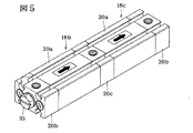
図5は図4に示す空気圧流路に設けられた目詰まり検出装置18を示す図であり、この目詰まり検出装置18は2つの検出装置本体18b,18cが一体となっており、2つの主ブロック部20aと2つの連通ブロック部20bと1つの共通ブロック部20cとを有している。この目詰まり検出装置18の主ブロック部20aと連通ブロック部20bの構造は、図2に示したものと同様となっている。共通ブロック部20cは、一方の検出装置本体18bの二次側ダイヤフラム室24に連通するとともに、他方の検出装置本体18cの一次側ダイヤフラム室22に連通するようになっており、一方の検出装置本体18bの二次側の連通ブロック部になるとともに、他方の検出装置本体18cの一次側の連通ブロック部になっている。
【0034】
一方の検出装置本体18bの連通ブロック部20bには、フィルタ10aの一次側の流路から分岐した流路19aが接続され、フィルタ10aの二次側の流路とフィルタ10bの一次側流路とを接続する流路から分岐した流路19bは共通ブロック部20cに接続されている。また、他方の検出装置本体18cの連通ブロック部20bには、フィルタ10bの二次側の流路から分岐した流路19cが接続されている。
【0035】
図4に示すように、直列に接続された2つのフィルタ10a,10b内のそれぞれのフィルタエレメントの目詰まり状況を、フィルタ10a,10bから離れた位置に設けられた目詰まり検出装置18によって検出することができる。
【0036】
図6は図4に示された空気圧流路に設けられる目詰まり検出装置の変形例を示す図であり、図5に示す目詰まり検出装置18にあっては検出装置本体18b,18cを直線状に連結したのに対して、図6に示す目詰まり検出装置18にあっては、検出装置本体18b,18cを並列に配置して、それぞれを共通ブロック部20dにより連結するようにしている。この共通ブロック部20dは、上流側の検出装置本体18b内の二次側ダイヤフラム室24に連通するとともに、下流側の検出装置本体18cの一次側ダイヤフラム室22に連通している。
【0037】
図4〜図6に示す場合には、直列に配置された複数の空気圧機器の目詰まり状況を検出するようにしているが、並列に配置された複数の空気圧機器の目詰まり状況を検出するようにしても良く、その場合には図1に示すタイプの目詰まり検出装置を複数個集中配置することができる。
【0038】
このように、フィルタなどの空気圧機器から離して目詰まり検出装置を配置するようにすると、複数の空気圧機器の目詰まり状況を集中して監視することができる。
【0039】
図7および図8は本発明の他の実施の形態である目詰まり検出装置18を示す図であり、この場合には図3に示したフィルタ10のポートブロック12に目詰まり検出装置18が直接取り付けられるようになっている。図7および図8においては、前記実施の形態における部材と共通する部材には同一の符号が付されている。
【0040】
この場合にはフィルタ10の一次側ポート14と目詰まり検出装置18の一次側ポート21とを連通させる一次側流路45がポートブロック12に形成され、フィルタ10の二次側ポート15と目詰まり検出装置18の二次側ポート23とを連通させる二次側流路46がポートブロック12に形成されている。一次側ポート21と二次側ポート23のそれぞれの開度を調整するために、それぞれの連通ブロック部20bには絞り弁47が設けられており、絞り弁47によってそれぞれのポート14,15の脈動がダイヤフラム室22,24に伝播されることを防止している。ただし、一方の流路のみに絞り弁を設けるようにしても良い。
【0041】
図1〜図6に示す目詰まり検出装置18に対しても、絞り弁47を取り付けるようにしても良く、その場合には、封止プラグ35を外してそれぞれダイヤフラム室22,24に連通させて絞り弁47に取り付けることができる。
【0042】
図9は本発明の他の実施の形態である目詰まり検出装置における図7と同様の部分を示す断面図である。この場合には、検出装置本体18aはフィルタ本体を構成するポートブロック12に一体に形成されており、その両端部にエンドキャップ48,49がねじ結合されて、それぞれのエンドキャップ48,49内に一次側ダイヤフラム室22と二次側ダイヤフラム室24とが形成されている。
【0043】
そして、前記実施の形態にあっては、絞り弁47がそれぞれの連通ブロック部20b,20cに設けられているのに対して、図9に示す場合には、それぞれのエンドキャップ48,49に小径の絞り流路48a,49aが形成され、これらの絞り流路48a,49aは固定絞りとなっている。このように、固定絞りを検出装置本体18aに設けることによって、検出装置本体18aの構造をより簡単にすることが可能となる。
【0044】
それぞれの実施の形態にあっては、目詰まり検出軸体31の位置を自動的にセンサ38により検出するようにしているが、図8において二点鎖線50に示すように、検出装置本体18aの主ブロック部20aに透明部材を設け、目詰まり検出軸体31を外部から作業者が目視することができるようにしても良い。その場合には、外部から目詰まり検出軸体31を観察することにより、その位置に応じてフィルタエレメント13の目詰まり状況を判別することができる。なお、透明部材50は目詰まり検出軸体31が外部から観察し得る領域に設けられていれば良いが、図7に示す場合には、検出装置本体18aのうち主ブロック部20a自体を透明部材により形成するようにしても良い。
【0045】
なお、図7および図9において符号51はフィルタエレメント13を取り付けるためのねじ孔であり、図7において符号52は軸収容孔25を外部に連通させる大気導入孔である。
【0046】
本発明は前記実施の形態に限定されるものではなく、その要旨を逸脱しない範囲で種々変更可能であることはいうまでもない。
【0047】
たとえば、図示する場合にはいずれもフィルタ10,10a,10bの目詰まりを検出するために本発明の目詰まり検出装置を適用しているが、オリフィスやエジェクタなどの他の空気圧機器の目詰まりを検出するためにも適用することができる。また、フィルタの目詰まりを検出する場合には、目詰まり状況を検出することができるフィルタとしては、前述したエアフィルタ、ミストフィルタおよびマイクロミストフィルタのいずれに対しても適用することができる。また、図示するフィルタ10はいずれも容器11を有しているが、容器11を有していないフィルタにも本発明を適用することができる。
【0048】
【発明の効果】
本発明によれば、目詰まり検出軸体に設けられた一次側と二次側のダイヤフラムによってそれぞれポートに連通するダイヤフラム室を形成したので、目詰まり検出軸体には移動抵抗が加わることなく、円滑に移動することになり、一次側ポートと二次側ポートとの圧力差により目詰まり検出軸体が移動してフィルタエレメントなどの空気圧機器の目詰まり状態を検出することができる。検出装置本体の少なくとも一部を透明部材として外部から目詰まり軸体を目視し得るようにすれば、目詰まり軸体の移動量に応じて空気圧機器の目詰まりを検出することができる。また、目詰まり検出軸体に永久磁石を設け、これに感応するセンサによって自動的に空気圧機器の目詰まり状態を検出して、その状態を点灯表示することができる。
【図面の簡単な説明】
【図1】本発明の一実施の形態である目詰まり検出装置を示す斜視図である。
【図2】図1の断面図である。
【図3】図1および図2に示された目詰まり検出装置をフイルタに接続した状態を示す断面図である。
【図4】直列に接続された2つのフィルタのそれぞれの目詰まりを検出するために2つの検出装置本体を一体にしたタイプの本発明の他の実施の形態である目詰まり検出装置を示す空気圧回路を示す回路図である。
【図5】図4に示された目詰まり検出装置を示す斜視図である。
【図6】図4に示す空気圧回路に使用される他のタイプの目詰まり検出装置を示す斜視図である。
【図7】本発明の目詰まり検出装置をフィルタに直接取り付けた場合を示す断面図である。
【図8】図7の平面図である。
【図9】本発明の他の実施の形態である目詰まり検出装置における図7と同様の部分を示す断面図である。
【符号の説明】
10,10a,10b フィルタ
11 容器
12 ポートブロック
13 フィルタエレメント
14 一次側ポート
15 二次側ポート
16 ドレンコック
18 目詰まり検出装置
18a 検出装置本体
21 一次側ポート
22 一次側ダイヤフラム室
23 二次側ポート
24 二次側ダイヤフラム室
26 一次側ダイヤフラム
27 ロッドカバー
28 二次側ダイヤフラム
31 目詰まり検出軸体
32 第1軸体
33 第2軸体
34 ばね部材
36 永久磁石
37 センサ取付溝
38 センサ
41 空気圧源
42 空気圧アクチュエータ
43 ピストンロッド
44 電磁弁
45 一次側流路
46 二次側流路
47 絞り弁
48,49 エンドブロック[0001]
BACKGROUND OF THE INVENTION
The present invention relates to a clogging detection device that detects clogging in pneumatic equipment such as filters, orifices, and ejectors used in a pneumatic control circuit.
[0002]
[Prior art]
The pneumatic control circuit has a filter that incorporates a filter element made of sintered metal, synthetic resin, or wire mesh to remove foreign matter, oil, and moisture contained in compressed air, and is used for flow measurement by a throttle mechanism. Orifices and ejectors for generating vacuum are used.
[0003]
The filter incorporates a filter element made of a porous sintered material and has a filtration degree of 5 μm, an air filter that removes moisture and dust, a filtration degree of 0.3 μm, And a mist filter that removes oil in addition to dust, and a micro mist filter that has a filtration degree of 0.01 μm and removes moisture, dust, and oil. These filters are connected in series and incorporated in the pneumatic control circuit, or a filter regulator in which the filter has a regulator function for regulating the pneumatic pressure is incorporated in the pneumatic control circuit. These filters include a filter storage container or bowl in which a filter element is incorporated, a port block portion provided with a primary side port through which unprocessed fluid flows and a secondary port through which processed fluid flows out. have.
[0004]
[Problems to be solved by the invention]
If foreign matter such as dust adheres to the filter element to cause clogging, compressed air having a predetermined flow rate and pressure cannot be supplied to the air pressure control circuit, so that the filter element needs to be replaced. Further, when the orifice is clogged, accurate flow rate measurement cannot be performed, and when the nozzle of the ejector is clogged, air having a predetermined degree of vacuum cannot be obtained.
[0005]
Therefore, when the pneumatic device cannot obtain a predetermined function due to clogging, it is necessary to replace the pneumatic device. This replacement work is performed by regularly performing maintenance on the equipment and the operator checking the clogging status of the equipment.
[0006]
However, depending on the pneumatic equipment, the clogging situation cannot be observed from the outside, and the pneumatic equipment must be removed, and it is not easy to detect the clogging situation.
[0007]
An object of the present invention is to make it possible to easily detect a clogged state of a pneumatic device.
[0008]
[Means for Solving the Problems]
The clogging detection device of the present invention includes a primary diaphragm chamber that communicates with an inflow side portion of a pneumatic device, a secondary diaphragm chamber that communicates with an outflow side portion of the pneumatic device, and a shaft housing between both of the diaphragm chambers. A detection device main body in which a hole is formed, a primary diaphragm that partitions the primary diaphragm chamber and the shaft receiving hole, and a secondary diaphragm that partitions the secondary diaphragm chamber and the shaft receiving hole are provided. A clogging detection shaft that is mounted in the shaft receiving hole so as to be capable of reciprocating in the axial direction, and a spring member that urges the clogging detection shaft to spring force toward the primary diaphragm. The clogging of the pneumatic device is detected based on the axial position of the clogging detection shaft body.
[0009]
In the clogging detection apparatus according to the present invention, a permanent magnet is provided on the clogging detection shaft, a sensor sensitive to the magnetic force of the permanent magnet is provided on the detection device body, and the clogging detection shaft is at a clogging display position. In such a case, the clogging state may be detected by the sensor. Furthermore, a transparent part may be provided in at least a part of the detection device main body so that the clogging detection shaft body can be visually observed from the outside through the transparent part. Further, a flow path is provided in at least one of a primary port that communicates the inflow side portion and the primary diaphragm chamber, and a secondary port that communicates the outflow side portion and the secondary diaphragm chamber. You may provide the throttle valve which adjusts the opening degree.
[0010]
The clogging device of the present invention may be provided at a position away from the pneumatic device where the clogging condition is detected, and a plurality of detection device bodies for detecting the clogging status of the pneumatic device are connected together. Anyway. The pneumatic device may be a filter.
[0011]
In the present invention, the clogging detection shaft body is provided with the primary side and secondary side diaphragms, and the diaphragm chambers communicated with the respective ports are formed by the diaphragms. Therefore, movement resistance is added to the clogging detection shaft body. The clogging detection shaft moves due to the pressure difference between the primary side port and the secondary side port, and the clogging state of the pneumatic equipment can be detected. If at least a part of the main body of the detection device is made a transparent member so that the clogged shaft body can be seen from the outside, the operator can visually detect clogging of the pneumatic equipment according to the amount of movement of the clogged shaft body. Can do. In addition, a permanent magnet is provided on the clogging detection shaft body, and a clogging state of the pneumatic device can be automatically detected by a sensor sensitive to the permanent magnet, and the state can be lit and displayed.
[0012]
DETAILED DESCRIPTION OF THE INVENTION
Hereinafter, embodiments of the present invention will be described in detail with reference to the drawings.
[0013]
FIG. 1 is a perspective view showing a clogging detection apparatus according to an embodiment of the present invention, FIG. 2 is a cross-sectional view of FIG. 1, and FIG. 3 is used to detect clogging of a filter. The case where it was used for is shown.
[0014]
As shown in FIG. 3, this
[0015]
The
[0016]
A drain cock 16 with a joint for removing moisture accumulated in the
[0017]
A
[0018]
A clogging
[0019]
The detection device
[0020]
One end of the
[0021]
A clogging
[0022]
As described above, the
[0023]
A
[0024]
When fluid is supplied to the
[0025]
When the
[0026]
Two screw holes are formed in each
[0027]
The clogging
[0028]
As described above, when the clogging
[0029]
There is a pressure difference between the pressure of the compressed air flowing into the
[0030]
On the other hand, when the
[0031]
A drain cock 16 for discharging the trapped liquid to the outside is provided at the bottom of the filter storage container. The drain cock 16 automatically has a liquid when the liquid reaches a predetermined liquid level. There are a type of auto drain that discharges liquid and a type that discharges liquid by manual operation, and it can be applied to either type.
[0032]
FIG. 4 is a view showing a pneumatic circuit for reciprocating the
[0033]
FIG. 5 is a diagram showing the clogging
[0034]
A
[0035]
As shown in FIG. 4, a clogging state of each filter element in the two
[0036]
FIG. 6 is a view showing a modification of the clogging detection device provided in the pneumatic flow path shown in FIG. 4. In the
[0037]
In the case shown in FIGS. 4 to 6, the clogging status of a plurality of pneumatic devices arranged in series is detected, but the clogging status of a plurality of pneumatic devices arranged in parallel is detected. In this case, a plurality of clogging detection devices of the type shown in FIG. 1 can be centrally arranged.
[0038]
As described above, when the clogging detection device is arranged away from the pneumatic device such as the filter, clogging situations of a plurality of pneumatic devices can be concentrated and monitored.
[0039]
7 and 8 are diagrams showing a
[0040]
In this case, a
[0041]
A
[0042]
FIG. 9 is a cross-sectional view showing the same part as FIG. 7 in the clogging detecting apparatus according to another embodiment of the present invention. In this case, the detection device
[0043]
In the embodiment, the
[0044]
In each of the embodiments, the position of the clogging
[0045]
7 and 9,
[0046]
It goes without saying that the present invention is not limited to the above-described embodiment, and various modifications can be made without departing from the scope of the invention.
[0047]
For example, in the illustrated case, the clogging detection device of the present invention is applied to detect clogging of the
[0048]
【The invention's effect】
According to the present invention, the diaphragm chambers communicating with the respective ports are formed by the primary side and secondary side diaphragms provided in the clogging detection shaft body, so that no movement resistance is added to the clogging detection shaft body, It moves smoothly, and the clogging detection shaft moves due to the pressure difference between the primary side port and the secondary side port, and the clogging state of the pneumatic equipment such as the filter element can be detected. If at least a part of the main body of the detection device is made a transparent member so that the clogged shaft body can be visually observed from the outside, clogging of the pneumatic device can be detected according to the amount of movement of the clogged shaft body. In addition, a permanent magnet is provided on the clogging detection shaft body, and a clogging state of the pneumatic device can be automatically detected by a sensor sensitive to the permanent magnet, and the state can be lit and displayed.
[Brief description of the drawings]
FIG. 1 is a perspective view showing a clogging detection apparatus according to an embodiment of the present invention.
FIG. 2 is a cross-sectional view of FIG.
FIG. 3 is a cross-sectional view showing a state in which the clogging detecting device shown in FIGS. 1 and 2 is connected to a filter.
FIG. 4 is a pneumatic diagram showing a clogging detection device according to another embodiment of the present invention in which two detection device bodies are integrated to detect clogging of each of two filters connected in series. It is a circuit diagram which shows a circuit.
FIG. 5 is a perspective view showing the clogging detection device shown in FIG. 4;
6 is a perspective view showing another type of clogging detection device used in the pneumatic circuit shown in FIG. 4. FIG.
FIG. 7 is a cross-sectional view showing a case where the clogging detection device of the present invention is directly attached to a filter.
8 is a plan view of FIG. 7. FIG.
FIG. 9 is a cross-sectional view showing a part similar to FIG. 7 in a clogging detection apparatus according to another embodiment of the present invention.
[Explanation of symbols]
10, 10a,
Claims (7)
前記一次側ダイヤフラム室と前記軸収容孔とを区画する一次側ダイヤフラム、および前記二次側ダイヤフラム室と前記軸収容孔とを区画する二次側ダイヤフラムが設けられ、前記軸収容孔内に軸方向に往復動自在に装着された目詰まり検出軸体と、
前記目詰まり検出軸体に前記一次側ダイヤフラムに向かうばね力を付勢するばね部材とを有し、
前記目詰まり検出軸体の軸方向の位置に基づいて前記空気圧機器の目詰まりを検出するようにしたことを特徴とする目詰まり検出装置。A detection device main body formed with a primary diaphragm chamber communicating with an inflow side portion of a pneumatic device, a secondary diaphragm chamber communicating with an outflow side portion of the pneumatic device, and a shaft housing hole between the two diaphragm chambers; ,
A primary diaphragm that partitions the primary diaphragm chamber and the shaft receiving hole, and a secondary diaphragm that partitions the secondary diaphragm chamber and the shaft receiving hole are provided, and an axial direction is provided in the shaft receiving hole. A clogging detection shaft mounted in a freely reciprocating manner,
A spring member that biases a spring force toward the primary diaphragm on the clogging detection shaft body;
A clogging detection apparatus, wherein clogging of the pneumatic device is detected based on an axial position of the clogging detection shaft body.
Priority Applications (1)
| Application Number | Priority Date | Filing Date | Title |
|---|---|---|---|
| JP06005099A JP4094158B2 (en) | 1999-03-08 | 1999-03-08 | Clogging detection device |
Applications Claiming Priority (1)
| Application Number | Priority Date | Filing Date | Title |
|---|---|---|---|
| JP06005099A JP4094158B2 (en) | 1999-03-08 | 1999-03-08 | Clogging detection device |
Publications (2)
| Publication Number | Publication Date |
|---|---|
| JP2000254431A JP2000254431A (en) | 2000-09-19 |
| JP4094158B2 true JP4094158B2 (en) | 2008-06-04 |
Family
ID=13130881
Family Applications (1)
| Application Number | Title | Priority Date | Filing Date |
|---|---|---|---|
| JP06005099A Expired - Fee Related JP4094158B2 (en) | 1999-03-08 | 1999-03-08 | Clogging detection device |
Country Status (1)
| Country | Link |
|---|---|
| JP (1) | JP4094158B2 (en) |
Families Citing this family (7)
| Publication number | Priority date | Publication date | Assignee | Title |
|---|---|---|---|---|
| JP2002196341A (en) * | 2000-12-27 | 2002-07-12 | Nec Eng Ltd | Sealing device for liquid crystal display cell |
| JP4275540B2 (en) * | 2004-01-15 | 2009-06-10 | 昭和電機株式会社 | Clogging detector for oil mist trapping filter and oil mist removing apparatus using the same |
| JP4504733B2 (en) * | 2004-05-07 | 2010-07-14 | シーケーディ株式会社 | air filter |
| JP5885548B2 (en) * | 2012-03-12 | 2016-03-15 | 株式会社神戸製鋼所 | Multi-channel device operating method and multi-channel device |
| JP6535647B2 (en) * | 2016-11-16 | 2019-06-26 | Ckd株式会社 | air filter |
| JP6910978B2 (en) * | 2018-03-09 | 2021-07-28 | Ckd株式会社 | Piston position detector |
| FR3132232B1 (en) * | 2022-02-01 | 2023-12-15 | Safran Helicopter Engines | VISUAL ANTI-FORGETTING SYSTEM OF A FILTER ELEMENT |
-
1999
- 1999-03-08 JP JP06005099A patent/JP4094158B2/en not_active Expired - Fee Related
Also Published As
| Publication number | Publication date |
|---|---|
| JP2000254431A (en) | 2000-09-19 |
Similar Documents
| Publication | Publication Date | Title |
|---|---|---|
| US2998138A (en) | Filter bypass indicator | |
| US4615800A (en) | Duplex filter apparatus | |
| EP1308816B1 (en) | Modular fluid pressure regulator with bypass | |
| JP4094158B2 (en) | Clogging detection device | |
| US6703937B1 (en) | Filtering apparatus for filtering compressed air | |
| US4064899A (en) | Control and signal arrangement for respirators | |
| CN108348826B (en) | System and method for integrating differential pressure sensors | |
| CA1082562A (en) | Automatic drain valve for a compressed air system | |
| KR20010023386A (en) | Fuel supply device for an internal combustion engine | |
| US5209253A (en) | Emergency shutoff valve and regulator assembly | |
| US9671038B2 (en) | Pilot valve with mechanical valve actuator | |
| RU2651481C2 (en) | Regulating device (options) for pressure regulation with filter condition detectors | |
| FI66692B (en) | STROEMNINGKAENSELORGAN KAENSLIGT FOER VAETSKESTROEMNINGAR INOMETT OMRAODE FRAON OEVER I FOERVAEG BESTAEMT MINIMUM TILL DUNR I FOERVAEG BESTAEMT MAXIMUM | |
| US3053389A (en) | Oil filters | |
| US7182855B1 (en) | Fuel filter with valve indicator | |
| EP0473261A2 (en) | Pressure regulating valve | |
| US3507391A (en) | Filter device | |
| US4468954A (en) | Device for determining the concentration of suspended solid contaminants in a fluid | |
| EP0639712B1 (en) | Compressor with integral filter | |
| JP2019219316A (en) | Filter differential pressure detection device | |
| GB2290145A (en) | Device for monitoring and detecting irregularities in a pressurised circuit | |
| US4598730A (en) | Flow control valve | |
| US20070056888A1 (en) | Filter change indicator | |
| US5950672A (en) | Twin filter for compressed air | |
| US7442292B2 (en) | Liquid visual display |
Legal Events
| Date | Code | Title | Description |
|---|---|---|---|
| A621 | Written request for application examination |
Free format text: JAPANESE INTERMEDIATE CODE: A621 Effective date: 20050407 |
|
| A977 | Report on retrieval |
Free format text: JAPANESE INTERMEDIATE CODE: A971007 Effective date: 20070226 |
|
| TRDD | Decision of grant or rejection written | ||
| A01 | Written decision to grant a patent or to grant a registration (utility model) |
Free format text: JAPANESE INTERMEDIATE CODE: A01 Effective date: 20080219 |
|
| A61 | First payment of annual fees (during grant procedure) |
Free format text: JAPANESE INTERMEDIATE CODE: A61 Effective date: 20080305 |
|
| FPAY | Renewal fee payment (event date is renewal date of database) |
Free format text: PAYMENT UNTIL: 20110314 Year of fee payment: 3 |
|
| R150 | Certificate of patent or registration of utility model |
Free format text: JAPANESE INTERMEDIATE CODE: R150 |
|
| S531 | Written request for registration of change of domicile |
Free format text: JAPANESE INTERMEDIATE CODE: R313531 |
|
| FPAY | Renewal fee payment (event date is renewal date of database) |
Free format text: PAYMENT UNTIL: 20110314 Year of fee payment: 3 |
|
| R350 | Written notification of registration of transfer |
Free format text: JAPANESE INTERMEDIATE CODE: R350 |
|
| FPAY | Renewal fee payment (event date is renewal date of database) |
Free format text: PAYMENT UNTIL: 20120314 Year of fee payment: 4 |
|
| FPAY | Renewal fee payment (event date is renewal date of database) |
Free format text: PAYMENT UNTIL: 20130314 Year of fee payment: 5 |
|
| FPAY | Renewal fee payment (event date is renewal date of database) |
Free format text: PAYMENT UNTIL: 20140314 Year of fee payment: 6 |
|
| R250 | Receipt of annual fees |
Free format text: JAPANESE INTERMEDIATE CODE: R250 |
|
| R250 | Receipt of annual fees |
Free format text: JAPANESE INTERMEDIATE CODE: R250 |
|
| LAPS | Cancellation because of no payment of annual fees |