JP4093726B2 - Image processing method, image processing apparatus, image processing program, and recording medium - Google Patents
Image processing method, image processing apparatus, image processing program, and recording medium Download PDFInfo
- Publication number
- JP4093726B2 JP4093726B2 JP2001047217A JP2001047217A JP4093726B2 JP 4093726 B2 JP4093726 B2 JP 4093726B2 JP 2001047217 A JP2001047217 A JP 2001047217A JP 2001047217 A JP2001047217 A JP 2001047217A JP 4093726 B2 JP4093726 B2 JP 4093726B2
- Authority
- JP
- Japan
- Prior art keywords
- pixel
- show
- image
- value
- image processing
- Prior art date
- Legal status (The legal status is an assumption and is not a legal conclusion. Google has not performed a legal analysis and makes no representation as to the accuracy of the status listed.)
- Expired - Fee Related
Links
- 238000012545 processing Methods 0.000 title claims description 61
- 238000003672 processing method Methods 0.000 title claims description 12
- 238000011946 reduction process Methods 0.000 claims description 8
- 238000002834 transmittance Methods 0.000 claims description 7
- 238000000034 method Methods 0.000 description 27
- 238000010586 diagram Methods 0.000 description 10
- 238000009499 grossing Methods 0.000 description 8
- 230000007547 defect Effects 0.000 description 4
- 239000006185 dispersion Substances 0.000 description 4
- 230000015572 biosynthetic process Effects 0.000 description 3
- 238000000605 extraction Methods 0.000 description 3
- 238000003786 synthesis reaction Methods 0.000 description 3
- 230000003044 adaptive effect Effects 0.000 description 2
- 238000011156 evaluation Methods 0.000 description 2
- 239000000203 mixture Substances 0.000 description 2
- 238000006073 displacement reaction Methods 0.000 description 1
- 230000000694 effects Effects 0.000 description 1
- 239000000463 material Substances 0.000 description 1
- 230000000116 mitigating effect Effects 0.000 description 1
- 230000000737 periodic effect Effects 0.000 description 1
- 238000012805 post-processing Methods 0.000 description 1
- 238000002310 reflectometry Methods 0.000 description 1
Images


Description
【0001】
【発明の属する技術分野】
本発明は、画像処理方法、画像処理装置、画像処理プログラム、及び記録媒体に関し、より詳細には、デジタル画像処理において裏写りや敷き写りを軽減する画像処理方法、画像処理装置、画像処理プログラム、及びそのプログラムを記録したコンピュータ読み取り可能な記録媒体に関する。
【0002】
【従来の技術】
従来の裏写り軽減技術の多くは、印刷物の両面をスキャナ等でデジタルデータとして取り込み、表裏両面のマッチングを採ることで裏写り成分を特定しようとするものである。これはブックスキャナと呼ばれ、両面の画像を読み込むために一般に装置が大型化し、かつ専用のハードウェアを必要とする。また表裏の画像のマッチングにおいては、非線型の位置ずれや紙の透過率の計算などの問題がある。この方式の例としては、例えば特開平5−22572号公報、特開平6−62216号公報、特開平8−265563号公報、特開平9−233319号公報、特開平9−312770号公報、特開平10−262147号公報、特開平11−41466号公報、特開2000−22946号公報、特開2000−92324号公報、特開2000−137355号公報、特開2000−188668号公報等に記載の発明がある。
【0003】
片面の画像から裏写り成分を軽減する方式としては、圧板の反射率を低く押さえる方式がある。例えば特開平11−298694号公報に記載の発明や特開平11−331561号公報に記載の発明が該当するが、原稿部以外の領域が出力で暗く出てしまう欠点がある。
【0004】
圧板等の機械的な工夫無しに片面の画像から裏写り成分を検出・軽減することを目的とした方式としては、特開平7−30757号公報に記載の発明がある。この方式は原稿の輝度のヒストグラムの分布からノイズ除去の閾値を決定することにより、通常の画像のみならず汚れの多い画像にも対応することをねらっているが、画像全体のヒストグラムが予め必要となることに加え、ノイズを除去する閾値を適応的に変化させるだけだから、例えば中間調領域に生じた裏写りに対しては、中間調ごと除去するか、そのまま裏写りが残るか、どちらかになってしまう。
【0005】
上記と同じ欠点を持つ方式としては、例えば特開平7−298055号公報、特開平10−65921号公報、特開平10−257325号公報、特開平11−187266号公報等に記載の発明がある。ここで挙げた方式はいずれも画像の濃度ヒストグラムを予め用意した評価関数の値により、画像濃度分布を適応的に変化させるものである。
【0006】
上記の欠点を克服し、中間調領域の裏写りへの対応を考えた方式として、特開平8−340447号公報に記載の発明がある。この方式では主に彩度情報から裏写り領域を特定し、該領域の濃度を選択的に変化させることにより、上記対応を行うことを目的としているが、裏面に彩度の高い文字や写真があった場合に対応できない。
【0007】
中間調領域の裏写りのみならず、裏面に高彩度領域がある場合でも裏写り軽減が可能であることを目的とした方式として、例えば、当出願人による特願平11−354412号明細書に記載の発明があるが、局所的背景色の推定のために、原稿中の網点等の構造を平滑化する必要があり、平滑化画像を基調とした出力となるために、原稿内部の細部の再現性に問題がある。
【0008】
【発明が解決しようとする課題】
裏写り軽減処理をはじめとする多くの画像処理では、局所的な色推定の精度を上げるために、初段で原画像を平滑化することが多い。該平滑化画像を用いた画像処理方法では、平滑化に起因するディフェクトは不可避である。このディフェクトには例えば過度の平滑化がある。
【0009】
本発明は、上述のごとき実情に鑑みてなされたものであり、入力画像が過度に平滑化されることを防ぎつつ、裏写りや敷き写りを軽減することが可能な画像処理方法、画像処理装置、画像処理プログラム、及び記録媒体を提供することをその目的とする。
【0010】
【課題を解決するための手段】
上述の理由から、写真等の中間調表現された領域でディフェクトが生じ易い。これを回避するためには出力画像も入力画像と同じ中間調表現を基調とすることが有効である。
【0011】
また平滑化に起因するディフェクトを回避するためには、平滑化以前の原画像から直接補正情報を抽出しなければならない。
【0012】
また過度の補正を防ぐためには、紙の透過率を考えて、検出された裏写り成分が妥当かどうかを判断する方法が有効である。この場合には紙の種類により透過率は異なるので、例えば新聞紙とそれ以外の紙で別々に予め統計的に透過率を計算しておくことが有効である。
【0013】
本発明に係る画像処理は、紙面に印刷された原稿をデジタルスキャナ等を用いてデジタル入力して得られるデジタル原画像に対して、局所的なウィンドウ内部での評価関数の値により、その後に裏写り軽減処理を施すか否かを決めることを特徴とする。
【0014】
また本発明に係る画像処理は、前記のように裏写り軽減処理を施した領域でも、該領域において検出された裏写り成分が、予め決めておいた閾値よりも大きい場合には、裏写り軽減処理を施さないようにすることで、裏写り補正処理の誤補正を修正する機能を持つことを特徴とする。
【0015】
また本発明に係る画像処理は、原稿の紙の質ごとに予め該閾値を計算しておくことで、多くの種類の原稿に対応できることを特徴とする。該閾値は処理の強度としてユーザ側で設定することもできる。
【0016】
請求項1の発明は、原稿を読み取って得られたデジタル原画像に対して行われた、裏写り補正を軽減させる裏写り軽減処理手段を有する画像処理装置であって、画素を中心とした特定の大きさのウィンドウ内における平均画素値と、該画素の裏写り軽減処理後の画素値との差分値を算出する差分算出手段と、画素におけるエッジの強度を算出するエッジ強度算出手段と、を備え、前記裏写り軽減処理手段は、前記原画像の各画素について、裏写り軽減処理の強度のパラメータTH1より、前記差分算出手段で算出した差分値が大きいときには、前記画素に対する原画像の画素値を出力し、前記パラメータTH1より前記差分値が小さく、且つ、前記エッジ強度算出手段で算出した前記画素におけるエッジの強度が、ノイズによるエッジと画像中の文字・写真等のエッジを区別する閾値TH2より大きい場合、前記画素に対する原画像の画素値を出力し、また、前記パラメータTH1より前記差分値が小さく、且つ、前記閾値TH2より前記エッジの強度が小さい場合、前記画素に対する原画像の画素値と前記差分値との差分を出力すること特徴とする画像処理装置である。
【0017】
請求項2の発明は、請求項1に記載の画像処理装置において、前記裏写り軽減処理の強度のパラメータTH1は、原稿ごとに予め統計的に算出された紙の透過率から算出しておくことを特徴としたものである。
【0018】
請求項3の発明は、請求項1に記載の画像処理装置において、前記ノイズによるエッジと画像中の文字・写真等のエッジを区別する閾値TH2は、原稿の紙の質ごとに予め統計的に算出しておくことを特徴としたものである。
【0019】
請求項4の発明は、請求項1に記載の画像処理装置において、前記エッジの強度は、ラプラシアンによって算出することを特徴としたものである。
【0023】
請求項5の発明は、原稿を読み取って得られたデジタル原画像に対して行われた、裏写り補正を軽減させる裏写り軽減処理ステップを有する画像処理方法であって、画素を中心とした特定の大きさのウィンドウ内における平均画素値と、該画素の裏写り軽減処理後の画素値との差分値を算出する差分算出ステップと、画素におけるエッジの強度を算出するエッジ強度算出ステップと、を備え、前記裏写り軽減処理ステップは、前記原画像の各画素について、裏写り軽減処理の強度のパラメータTH1より、前記差分算出手段で算出した差分値が大きいときには、前記画素に対する原画像の画素値を出力し、前記パラメータTH1より前記差分値が小さく、且つ、前記エッジ強度算出手段で算出した前記画素におけるエッジの強度が、ノイズによるエッジと画像中の文字・写真等のエッジを区別する閾値TH2より大きい場合、前記画素に対する原画像の画素値を出力し、また、前記パラメータTH1より前記差分値が小さく、且つ、前記閾値TH2より前記エッジの強度が小さい場合、前記画素に対する原画像の画素値と前記差分値との差分を出力すること特徴とする画像処理方法である。
【0030】
請求項6の発明は、請求項1乃至4のいずれかに記載の画像処理装置の各手段としてコンピュータを機能させるための画像処理プログラムである。
請求項7の発明は、コンピュータが読み取り可能な記録媒体であって、請求項6に記載の画像処理プログラムを記録したことを特徴とする記録媒体である。
【0038】
【発明の実施の形態】
図1は、本発明の一実施形態による画像処理装置を説明するためのモジュール構成図である。本実施形態において、スキャナ,デジタルカメラ等の画像入力機器1から入力された画像は、RAM6に蓄積される。また後述する一連の処理はROM7に蓄積されたプログラムをCPU5が読み出すことによって実行される。また処理の途中経過や途中結果はCRT等の表示装置2を通じてユーザに提示され、必要な場合にはキーボード3からユーザが処理に必要なパラメータを入力指定する。後述する処理の実行中に作られる中間データはRAM6に蓄積され、必要に応じてCPU5によって読み出し、修正・書き込みが行われる。一連の処理の結果として生成された画像は、その後の画像処理に使用されるか、もしくはRAM6から読み出されて、画像印刷機器(プリンタ)4に出力される。
【0039】
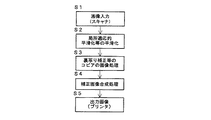
図2は、本発明の一実施形態に係る画像処理方法を説明するためのフロー図である。本発明は主にデジタル複写機の中の画像処理に相当する。本発明の後には色補正等、通常の複写機における処理が行われる。
【0040】
スキャナ1によって画像が入力された後(ステップS1)、その画像に、局所適応的平滑化等の平滑化処理を行う(ステップS2)。次に、裏写り補正等のコピアの画像処理を行う(ステップS3)。この画像処理の後、補正画像を合成する補正画像合成処理を施し(ステップS4)、画像をプリンタ等で出力する(ステップS5)。ここで、裏写り補正処理、すなわち裏写り除去処理は、例えば、特願平11−354412号及び特願2000−23433号明細書に記載の方法を用いる。
【0041】
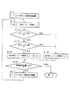
図3は、裏写り補正画像合成処理を詳細に説明するためのフロー図であり、局所適応的エッジ保持平滑化処理を説明するためのフロー図である。上で述べたようにこの合成処理は主に裏写り軽減処理の後処理として考えているため、該処理の出力であるデジタルデータを入力画像とする。
【0042】
まず、従来技術の説明で述べた方式等による裏写り軽減処理が行われ、その出力が得られたとする。ステップS11のスキャン順の先頭画素の位置(i,j)に対して、最初にその裏写り軽減処理出力画像と、そのもとになった平滑化された入力画像との差分d(i,j)=AVG(i,j)−STEM(i,j)を計算する(ステップS12)。ここで、AVG(i,j)は位置(i,j)の画素を中心としたn×nのウィンドウ内における平均、STEM(i,j)は位置(i,j)における裏写り軽減処理の出力を指す。その差分d(i,j)は裏写り成分画像であり、平滑化画像と同じ解像度で得ることができる。
【0043】
次に、ステップS13において、差分画像中の画素値|d(i,j)|が、予め決められた閾値TH1よりも大きい画素については、裏写り軽減処理における誤りとみなし、この画素については入力画像の画素値INPUT(i,j)をそのまま出力OUTPUT(i,j)とする(ステップS18)。この画素を条件1を満たす画素とする。ここで閾値TH1は紙の透過率と相関があるから、予め代表的な紙の種類についてはTH1を統計的に求めておくことができる。また、TH1は裏写りと原稿前面の画像を分別するものであるから、これを裏写り軽減処理の強度のパラメータとみなし、ユーザ側で設定することもできる。
【0044】
上記条件1を満たさない画素についてのみ、すなわちステップS13においてYESと判断された場合にのみ、次に以下の計算をする。
その画素の位置を(i,j)とし、入力画像、すなわち原画像中の(i,j)におけるエッジの強度|E(i,j)|を計算する。このエッジ強度計算には例えばラプラシアンによる計算がある。
【0045】
また網点で表現された画像から文字等のエッジを抽出するのに都合の良い、以下のようなフィルタを用いても良い。
【0046】
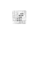
図4は、方位選択性を持つ小ウィンドウを説明するための図である。
網点で表現された画像中の注目画素を中心とする斜め方向の小ウィンドウ×4,垂直・水平方向の小ウィンドウ×4の合わせて8つの方位選択性ウィンドウを考える。これは注目画素を含む8方位のウィンドウ(方位選択性ウィンドウと呼ぶ)の集合である。例えば、図4中、灰色丸(注目画素)で表わした注目画素と、黒丸(●)で示した画素が右上ウィンドウとなり、灰色丸と白丸(○)が下ウィンドウとなる。同じように他の方位も定義する。
【0047】
各方位選択性ウィンドウについてその内部での画素値の平均を計算する。文字等のエッジ部分以外を考えた場合、網点は2次元の周期構造であるから、方位選択性ウィンドウの大きさが適当であれば、その平均間の分散は網点1周期の分散以下になる。文字等のエッジは直線性が高いために、上のような方位間の平均を計算した場合には、その分散が大きくなる。
以上のような特徴を用いて、閾値を適当に定めることにより、網点で表現された画像から、文字等のエッジを抽出することができる。
【0048】
ステップS14において、エッジ強度|E(i,j)|が、予め決めてある閾値TH2を超える画素については、明らかに原稿前面画像の一部であるとみなし、この画素については入力画像の画素値をそのまま出力とする(ステップS18)。この画素を条件2を満たす画素とする。
【0049】
TH2はノイズによるエッジと、画像中の文字・写真等のエッジを分けるものであるから、予め代表的な種類の紙について妥当な値を設定しておくことができる。またユーザ側で設定することもできる。
【0050】
次に条件1を満たさず、かつ条件2を満たさない画素についてのみ、平滑化される前の原画像INPUT(i,j)と上記非前面成分d(i,j)との差分を取り、これを出力OUTPUT(i,j)とする(ステップS15)。ここで処理される画素を条件3を満たす画素とする。
【0051】
上記条件1、条件2、及び条件3によりすべての画素が処理される。すなわち、ステップS16において全画素を処理したかを判断し、処理済みであれば終了し、未処理の画素があれば、ステップS17においてスキャン順の次の画素に示す位置(i,j)に対するステップS12以降の処理を続行する。入力画像のすべてに画素について、各条件を計算する場合に比べ、上記のように条件を絞り込むことにより、計算量を削減することができる。
【0052】
本発明の画像処理の後には例えば孤立点除去や色補正、領域識別等の通常のコピア搭載の画像処理が施される。
【0053】
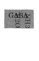
図5に中間調領域に生じた裏写りの例を示し、図6に従来の裏写り軽減処理を施した後の出力の例を示している。図7は、図4の方法によるエッジ抽出の例を示す図であり、図6にエッジ抽出フィルタを掛けたものを示している。網点上の裏写りは、方位間の分散を縮小する方向に働くため、閾値を適当に設定することにより前景の文字等の強いエッジのみ取り出すことができる。
図8は、裏写り軽減処理及び補正画像合成処理を施した後の出力画像の例を示す図である。入力画像と同じように網点で再現されることにより、前景文字の細部まで再現される。
【0054】
以上、本発明の画像処理方法及び装置を説明してきたが、本発明の実施形態としては、図1を用いた説明で触れたように、コンピュータに、これらの画像処理方法を実行させるための、或いは画像処理装置として機能させるための画像処理プログラム、及び該プログラムを記録したコンピュータ読み取り可能な記録媒体としても可能である。
【0055】
【発明の効果】
本発明によれば、写真等の中間調表現された領域に対して裏写りを軽減しつつ、原画像と同じ中間調表現の出力画像を合成することができる。また、本発明によれば、裏写り成分の大きさにより処理を切り替えることにより、裏写り補正処理の誤補正を修正することができる。また、原稿中の細部の再現性を向上させることができる。さらに、入出力の中間調表現形態が同じであることから、裏写り軽減処理全体をモジュール化して扱うことができる。
【図面の簡単な説明】
【図1】 本発明の一実施形態による画像処理装置を説明するためのモジュール構成図である。
【図2】 本発明の一実施形態に係る画像処理方法を説明するためのフロー図である。
【図3】 裏写り補正画像合成処理を詳細に説明するためのフロー図である。
【図4】 方位選択性を持つ小ウィンドウを説明するための図である。
【図5】 中間調領域に生じた裏写りの例を示す図である。
【図6】 従来の裏写り軽減処理を施した後の出力画像の例を示す図である。
【図7】 図4の方法によるエッジ抽出の例を示す図である。
【図8】 裏写り軽減処理及び補正画像合成処理を施した後の出力画像の例を示す図である。
【符号の説明】
1…画像入力機器(スキャナ)、2…表示装置、3…キーボード、4…画像印刷機器(プリンタ)、5…CPU、6…RAM、7…ROM。[0001]
BACKGROUND OF THE INVENTION
The present invention, images processing method, images processing device, images processing program, and a recording medium, and more particularly, images processing how to reduce show-through and laying-through in the digital picture image processing, image image processing apparatus, images processing program, and a computer-readable recording medium storing the program.
[0002]
[Prior art]
Many of the conventional show-through reduction techniques try to specify a show-through component by taking both sides of a printed material as digital data with a scanner or the like, and matching the both sides. This is called a book scanner, and generally requires a large-sized apparatus and special hardware in order to read double-sided images. Further, in matching of the front and back images, there are problems such as non-linear displacement and calculation of paper transmittance. Examples of this method include, for example, JP-A-5-22572, JP-A-6-62216, JP-A-8-265563, JP-A-9-233319, JP-A-9-321770, Inventions described in JP-A-10-262147, JP-A-11-41466, JP-A-2000-22946, JP-A-2000-92324, JP-A-2000-137355, JP-A-2000-188668, etc. There is.
[0003]
As a method for reducing the show-through component from an image on one side, there is a method for reducing the reflectivity of the pressure plate. For example, the invention described in Japanese Patent Application Laid-Open No. 11-298694 and the invention described in Japanese Patent Application Laid-Open No. 11-331561 are applicable, but there is a drawback that an area other than the original portion appears dark in the output.
[0004]
As a method for detecting and reducing a show-through component from a single-sided image without a mechanical device such as a pressure plate, there is an invention described in JP-A-7-30757. This method aims to deal with not only normal images but also images with much dirt by determining the noise removal threshold from the distribution of the luminance histogram of the document. However, a histogram of the entire image is required in advance. In addition, the threshold for noise removal is only adaptively changed. For example, for show-through that occurs in the halftone area, either the halftone is removed or the show-through remains. turn into.
[0005]
Examples of the system having the same drawbacks as described above include inventions described in JP-A-7-298055, JP-A-10-65921, JP-A-10-257325, JP-A-11-187266, and the like. In any of the methods mentioned here, the image density distribution is adaptively changed by the value of the evaluation function prepared in advance for the density histogram of the image.
[0006]
Japanese Patent Laid-Open No. 8-340447 discloses an invention that overcomes the above-described drawbacks and considers the response to show-through in a halftone area. The purpose of this method is to specify the show-through area mainly from the saturation information and selectively change the density of the area, but the above-mentioned correspondence is intended. Cannot handle when there is.
[0007]
For example, Japanese Patent Application No. 11-354412 by the applicant of the present application describes a method for reducing the show-through in the case where there is a high-saturation region on the back as well as the half-tone region. However, in order to estimate the local background color, it is necessary to smooth the structure such as halftone dots in the original, and since the output is based on the smoothed image, There is a problem with reproducibility.
[0008]
[Problems to be solved by the invention]
In many image processes such as the show-through reduction process, the original image is often smoothed at the first stage in order to increase the accuracy of local color estimation. In the image processing method using the smoothed image, defects due to smoothing are unavoidable. This defect includes, for example, excessive smoothing.
[0009]
The present invention has been made in view of such circumstances described above, while preventing that the input image is excessively smoothed, images processing method capable of reducing show-through and laying-through, images processor, images processing program, and to provide a recording medium and an object.
[0010]
[Means for Solving the Problems]
For the reasons described above, defects are likely to occur in a halftone-expressed area such as a photograph. In order to avoid this, it is effective that the output image is based on the same halftone expression as the input image.
[0011]
In order to avoid defects caused by smoothing, correction information must be directly extracted from the original image before smoothing.
[0012]
In order to prevent excessive correction, it is effective to determine whether or not the detected show-through component is appropriate in consideration of the transmittance of the paper. In this case, since the transmittance varies depending on the type of paper, for example, it is effective to statistically calculate the transmittance separately separately for newspaper and other paper.
[0013]
Engaging Ru images processed with the present invention, with respect to digital RuHara image obtained by the printing is the document on paper and digital input using a digital scanner or the like, the value of the evaluation function within local window Then, it is determined whether or not to perform the show-through reduction processing.
[0014]
The engagement Ru images processed with the present invention, even in a region subjected to show-through mitigation processing as described above, when the show-through components detected in the region is greater than a threshold value determined in advance, the back It is characterized by having a function of correcting erroneous correction of the show-through correction process by not performing the reflection reduction process.
[0015]
The engagement Ru images processed with the present invention, by leaving computed in advance threshold values for each quality of paper document, characterized in that accommodate many types of documents. The threshold can also be set by the user as the processing intensity.
[0016]
The invention according to
[0017]
According to a second aspect of the present invention, in the image processing apparatus according to the first aspect, the parameter TH1 of the intensity of the show-through reduction processing is calculated from the paper transmittance statistically calculated in advance for each original. It is characterized by.
[0018]
According to a third aspect of the present invention, in the image processing apparatus according to the first aspect, the threshold value TH2 for distinguishing between the edge caused by noise and the edge of characters / photos in the image is statistically determined in advance for each paper quality of the document. It is characterized by calculating.
[0019]
According to a fourth aspect of the present invention, in the image processing apparatus according to the first aspect, the edge strength is calculated by a Laplacian.
[0023]
According to a fifth aspect of the present invention , there is provided an image processing method having a show-through reduction processing step for reducing a show-through correction performed on a digital original image obtained by reading a document, wherein the identification is performed centering on pixels. A difference calculating step for calculating a difference value between an average pixel value in a window of a size and a pixel value after the show-through reduction processing of the pixel, and an edge strength calculating step for calculating an edge strength of the pixel. And the show-through reduction processing step includes a pixel value of the original image with respect to each pixel of the original image when the difference value calculated by the difference calculation means is larger than a parameter TH1 of the intensity of the show-through reduction processing. And the difference value is smaller than the parameter TH1, and the edge intensity in the pixel calculated by the edge intensity calculating means is noise. The pixel value of the original image for the pixel is output, the difference value is smaller than the parameter TH1, and the threshold value TH2 is output. In the image processing method, the difference between the pixel value of the original image for the pixel and the difference value is output when the edge intensity is smaller.
[0030]
A sixth aspect of the present invention is an image processing program for causing a computer to function as each means of the image processing apparatus according to any one of the first to fourth aspects.
The invention according to
[0038]
DETAILED DESCRIPTION OF THE INVENTION
Figure 1 is a module configuration diagram for describing the images processing device that by the embodiment of the present invention. In this embodiment, scanner, images input from the
[0039]
Figure 2 is a flowchart for explaining the engagement Ru images processing method in an embodiment of the present invention. The present invention mainly corresponds to the image processing in the digital copier. After the present invention, processing in a normal copying machine such as color correction is performed.
[0040]
After the images is input by the scanner 1 (step S1), the in the image, performs the smoothing processing such as local adaptive smoothing (step S2). Next, copier image processing such as show-through correction is performed (step S3). After this image processing, corrected image combining processing for combining corrected images is performed (step S4), and the image is output by a printer or the like (step S5). Here, in the show-through correction process, that is, the show-through removal process, for example, a method described in Japanese Patent Application Nos. 11-35412 and 2000-23433 is used.
[0041]
FIG. 3 is a flowchart for explaining the show-through corrected image composition processing in detail, and is a flowchart for explaining the local adaptive edge holding smoothing processing. As described above, since this synthesis processing is mainly considered as post-processing of the show-through reduction processing, digital data that is the output of the processing is used as an input image.
[0042]
First, it is assumed that the show-through reduction processing by the method described in the description of the prior art is performed and the output is obtained. For the position (i, j) of the first pixel in the scan order in step S11, the difference d (i, j) between the output image of the show-through reduction processing and the smoothed input image that is the basis thereof first. ) = AVG (i, j) -STEM (i, j) is calculated (step S12). Here, AVG (i, j) is an average in an n × n window centered on the pixel at position (i, j), and STEM (i, j) is the amount of show-through reduction processing at position (i, j). Refers to the output. The difference d (i, j) is a show-through component image and can be obtained with the same resolution as the smoothed image.
[0043]
Next, in step S13, a pixel whose pixel value | d (i, j) | in the difference image is larger than a predetermined threshold TH1 is regarded as an error in the show-through reduction processing, and this pixel is input. The pixel value INPUT (i, j) of the image is used as the output OUTPUT (i, j) as it is (step S18). This pixel is assumed to satisfy the
[0044]
Only for pixels that do not satisfy the
The position of the pixel is (i, j), and the edge strength | E (i, j) | at the input image, that is, (i, j) in the original image is calculated. For example, Laplacian calculation is used as the edge strength calculation.
[0045]
Further, the following filter that is convenient for extracting an edge such as a character from an image expressed by halftone dots may be used.
[0046]
FIG. 4 is a diagram for explaining a small window having orientation selectivity.
Consider eight azimuth-selectivity windows, which are a small window x 4 in the diagonal direction centered on the pixel of interest in the image represented by halftone dots, and a small window x 4 in the vertical and horizontal directions. This is a set of eight azimuth windows (referred to as azimuth selectivity windows) including the target pixel. For example, in FIG. 4, a pixel of interest represented by a gray circle (pixel of interest) and a pixel represented by a black circle (●) are the upper right window, and a gray circle and a white circle (◯) are the lower window. Similarly, other orientations are defined.
[0047]
Calculate the average of the pixel values within each orientation selectivity window. Considering other than the edge portion of characters, etc., the halftone dots have a two-dimensional periodic structure. Therefore, if the size of the orientation selectivity window is appropriate, the dispersion between the averages is less than the dispersion of one halftone dot period. Become. Since edges of characters and the like have high linearity, when the average between the above orientations is calculated, the dispersion becomes large.
By appropriately determining the threshold value using the features as described above, it is possible to extract an edge such as a character from an image represented by a halftone dot.
[0048]
In step S14, a pixel whose edge intensity | E (i, j) | exceeds a predetermined threshold TH2 is clearly regarded as a part of the document front image, and the pixel value of the input image for this pixel. Is output as it is (step S18). This pixel is assumed to satisfy the
[0049]
Since TH2 separates an edge caused by noise and an edge of characters / photographs in an image, an appropriate value can be set in advance for a typical type of paper. It can also be set by the user.
[0050]
Next, the difference between the original image INPUT (i, j) before smoothing and the non-frontal component d (i, j) is calculated only for pixels that do not satisfy
[0051]
All the pixels are processed according to the
[0052]
After the images processing of the present invention are, for example, isolated point removal and color correction, image processing of a normal copier mounting region identification etc. is performed.
[0053]
FIG. 5 shows an example of show-through occurring in the halftone area, and FIG. 6 shows an example of output after the conventional show-through reduction processing. FIG. 7 is a diagram showing an example of edge extraction by the method of FIG. 4 and shows the result of applying an edge extraction filter to FIG. Since the show-through on the halftone dot works in a direction to reduce the dispersion between the azimuths, only strong edges such as foreground characters can be taken out by appropriately setting the threshold value.
FIG. 8 is a diagram illustrating an example of an output image after performing the show-through reduction process and the corrected image synthesis process. The details of foreground characters are reproduced by being reproduced with halftone dots in the same manner as the input image.
[0054]
Having thus described the images processing method and apparatus of the present invention, as an embodiment of the present invention, as mentioned in the description with reference to FIG. 1, the computer, in order to perform these images processing method of walk is also possible as images processing program, and a computer-readable recording medium recording the program for functioning as an image picture processor.
[0055]
【The invention's effect】
According to the present invention, it is possible to synthesize an output image having the same halftone expression as that of the original image while reducing the show-through in a halftone expression area such as a photograph. Further, according to the present invention, the erroneous correction of the show-through correction process can be corrected by switching the process according to the size of the show-through component. In addition, the reproducibility of details in a document can be improved. Further, since the input / output halftone expression form is the same, the entire show-through reduction process can be handled as a module.
[Brief description of the drawings]
1 is a module configuration diagram for explaining by that images processing device according to an embodiment of the present invention.
Is a flowchart for explaining the engagement Ru images processing method in an embodiment of the present invention; FIG.
FIG. 3 is a flowchart for explaining in detail a show-through corrected image composition process;
FIG. 4 is a diagram for explaining a small window having orientation selectivity.
FIG. 5 is a diagram illustrating an example of show-through that occurs in a halftone area.
FIG. 6 is a diagram illustrating an example of an output image after performing a conventional show-through reduction process.
7 is a diagram illustrating an example of edge extraction by the method of FIG. 4;
FIG. 8 is a diagram illustrating an example of an output image after performing a show-through reduction process and a corrected image synthesis process.
[Explanation of symbols]
DESCRIPTION OF
Claims (7)
Priority Applications (1)
| Application Number | Priority Date | Filing Date | Title |
|---|---|---|---|
| JP2001047217A JP4093726B2 (en) | 2001-02-22 | 2001-02-22 | Image processing method, image processing apparatus, image processing program, and recording medium |
Applications Claiming Priority (1)
| Application Number | Priority Date | Filing Date | Title |
|---|---|---|---|
| JP2001047217A JP4093726B2 (en) | 2001-02-22 | 2001-02-22 | Image processing method, image processing apparatus, image processing program, and recording medium |
Publications (3)
| Publication Number | Publication Date |
|---|---|
| JP2002252766A JP2002252766A (en) | 2002-09-06 |
| JP2002252766A5 JP2002252766A5 (en) | 2006-03-02 |
| JP4093726B2 true JP4093726B2 (en) | 2008-06-04 |
Family
ID=18908686
Family Applications (1)
| Application Number | Title | Priority Date | Filing Date |
|---|---|---|---|
| JP2001047217A Expired - Fee Related JP4093726B2 (en) | 2001-02-22 | 2001-02-22 | Image processing method, image processing apparatus, image processing program, and recording medium |
Country Status (1)
| Country | Link |
|---|---|
| JP (1) | JP4093726B2 (en) |
Families Citing this family (1)
| Publication number | Priority date | Publication date | Assignee | Title |
|---|---|---|---|---|
| JP4853653B2 (en) | 2006-07-15 | 2012-01-11 | 富士ゼロックス株式会社 | Image processing apparatus and image processing program |
-
2001
- 2001-02-22 JP JP2001047217A patent/JP4093726B2/en not_active Expired - Fee Related
Also Published As
| Publication number | Publication date |
|---|---|
| JP2002252766A (en) | 2002-09-06 |
Similar Documents
| Publication | Publication Date | Title |
|---|---|---|
| US7944588B2 (en) | Image correction processing apparatus, image correction processing method, program, and storage medium | |
| JP4396324B2 (en) | Method for determining halftone area and computer program | |
| JP3768052B2 (en) | Color image processing method, color image processing apparatus, and recording medium therefor | |
| JP4112362B2 (en) | System and method for enhancing scanned document images for color printing | |
| US11308318B2 (en) | Image processing apparatus, image processing method, and storage medium | |
| JP4890973B2 (en) | Image processing apparatus, image processing method, image processing program, and storage medium | |
| US11069068B2 (en) | Image processing apparatus that performs multi-crop processing, method of generating image in units of documents by multi-crop processing and storage medium | |
| US20060152765A1 (en) | Image processing apparatus, image forming apparatus, image reading process apparatus, image processing method, image processing program, and computer-readable storage medium | |
| JP2005348103A (en) | Image correcting device, image reader, program, and storage medium | |
| JP4093726B2 (en) | Image processing method, image processing apparatus, image processing program, and recording medium | |
| JP4111697B2 (en) | Image brightness correction apparatus, image reading apparatus, image forming apparatus, and program | |
| JP4084537B2 (en) | Image processing apparatus, image processing method, recording medium, and image forming apparatus | |
| JP2017135690A (en) | Image processing device, image processing method, and program | |
| JP2002158872A (en) | Image processing method, image processor and recording medium | |
| JP4073877B2 (en) | Image processing method, image processing apparatus, image forming apparatus, and computer program | |
| JP3989687B2 (en) | Color image processing method, color image processing apparatus, color image processing program, and recording medium | |
| JP3865651B2 (en) | Color image processing method, color image processing apparatus, program, and recording medium | |
| JP3977112B2 (en) | Color image processing method and color image processing apparatus | |
| JP3877535B2 (en) | Color image processing method, color image processing apparatus, color image processing program, and recording medium | |
| JP3894834B2 (en) | Image processing apparatus, image processing method, program, and recording medium | |
| JP2003274182A (en) | Method and device for processing color image, program and recording medium | |
| JP2004056710A (en) | Color image processing apparatus, color image processing method, program, and recording medium | |
| JP2004104662A (en) | Image forming device | |
| JP3957523B2 (en) | Color image processing apparatus, color image processing method, program, and recording medium | |
| JP2007166429A (en) | Unit and method for processing image, program, and storage medium storing the same |
Legal Events
| Date | Code | Title | Description |
|---|---|---|---|
| A621 | Written request for application examination |
Free format text: JAPANESE INTERMEDIATE CODE: A621 Effective date: 20050316 |
|
| A521 | Request for written amendment filed |
Free format text: JAPANESE INTERMEDIATE CODE: A523 Effective date: 20060111 |
|
| A977 | Report on retrieval |
Free format text: JAPANESE INTERMEDIATE CODE: A971007 Effective date: 20070517 |
|
| A131 | Notification of reasons for refusal |
Free format text: JAPANESE INTERMEDIATE CODE: A131 Effective date: 20070522 |
|
| A521 | Request for written amendment filed |
Free format text: JAPANESE INTERMEDIATE CODE: A523 Effective date: 20070531 |
|
| TRDD | Decision of grant or rejection written | ||
| A01 | Written decision to grant a patent or to grant a registration (utility model) |
Free format text: JAPANESE INTERMEDIATE CODE: A01 Effective date: 20080304 |
|
| A61 | First payment of annual fees (during grant procedure) |
Free format text: JAPANESE INTERMEDIATE CODE: A61 Effective date: 20080304 |
|
| FPAY | Renewal fee payment (event date is renewal date of database) |
Free format text: PAYMENT UNTIL: 20110314 Year of fee payment: 3 |
|
| R150 | Certificate of patent or registration of utility model |
Free format text: JAPANESE INTERMEDIATE CODE: R150 |
|
| FPAY | Renewal fee payment (event date is renewal date of database) |
Free format text: PAYMENT UNTIL: 20120314 Year of fee payment: 4 |
|
| FPAY | Renewal fee payment (event date is renewal date of database) |
Free format text: PAYMENT UNTIL: 20130314 Year of fee payment: 5 |
|
| FPAY | Renewal fee payment (event date is renewal date of database) |
Free format text: PAYMENT UNTIL: 20140314 Year of fee payment: 6 |
|
| LAPS | Cancellation because of no payment of annual fees |