JP4093623B2 - Printer cartridge having replaceable ink container - Google Patents
Printer cartridge having replaceable ink container Download PDFInfo
- Publication number
- JP4093623B2 JP4093623B2 JP00855398A JP855398A JP4093623B2 JP 4093623 B2 JP4093623 B2 JP 4093623B2 JP 00855398 A JP00855398 A JP 00855398A JP 855398 A JP855398 A JP 855398A JP 4093623 B2 JP4093623 B2 JP 4093623B2
- Authority
- JP
- Japan
- Prior art keywords
- ink
- cartridge
- chassis
- reservoir
- printer
- Prior art date
- Legal status (The legal status is an assumption and is not a legal conclusion. Google has not performed a legal analysis and makes no representation as to the accuracy of the status listed.)
- Expired - Fee Related
Links
Images


Classifications
-
- B—PERFORMING OPERATIONS; TRANSPORTING
- B41—PRINTING; LINING MACHINES; TYPEWRITERS; STAMPS
- B41J—TYPEWRITERS; SELECTIVE PRINTING MECHANISMS, i.e. MECHANISMS PRINTING OTHERWISE THAN FROM A FORME; CORRECTION OF TYPOGRAPHICAL ERRORS
- B41J2/00—Typewriters or selective printing mechanisms characterised by the printing or marking process for which they are designed
- B41J2/005—Typewriters or selective printing mechanisms characterised by the printing or marking process for which they are designed characterised by bringing liquid or particles selectively into contact with a printing material
- B41J2/01—Ink jet
- B41J2/17—Ink jet characterised by ink handling
- B41J2/175—Ink supply systems ; Circuit parts therefor
- B41J2/17503—Ink cartridges
- B41J2/17553—Outer structure
-
- B—PERFORMING OPERATIONS; TRANSPORTING
- B41—PRINTING; LINING MACHINES; TYPEWRITERS; STAMPS
- B41J—TYPEWRITERS; SELECTIVE PRINTING MECHANISMS, i.e. MECHANISMS PRINTING OTHERWISE THAN FROM A FORME; CORRECTION OF TYPOGRAPHICAL ERRORS
- B41J2/00—Typewriters or selective printing mechanisms characterised by the printing or marking process for which they are designed
- B41J2/005—Typewriters or selective printing mechanisms characterised by the printing or marking process for which they are designed characterised by bringing liquid or particles selectively into contact with a printing material
- B41J2/01—Ink jet
- B41J2/17—Ink jet characterised by ink handling
- B41J2/175—Ink supply systems ; Circuit parts therefor
- B41J2/17503—Ink cartridges
- B41J2/17513—Inner structure
-
- B—PERFORMING OPERATIONS; TRANSPORTING
- B41—PRINTING; LINING MACHINES; TYPEWRITERS; STAMPS
- B41J—TYPEWRITERS; SELECTIVE PRINTING MECHANISMS, i.e. MECHANISMS PRINTING OTHERWISE THAN FROM A FORME; CORRECTION OF TYPOGRAPHICAL ERRORS
- B41J2/00—Typewriters or selective printing mechanisms characterised by the printing or marking process for which they are designed
- B41J2/005—Typewriters or selective printing mechanisms characterised by the printing or marking process for which they are designed characterised by bringing liquid or particles selectively into contact with a printing material
- B41J2/01—Ink jet
- B41J2/17—Ink jet characterised by ink handling
- B41J2/175—Ink supply systems ; Circuit parts therefor
- B41J2/17503—Ink cartridges
- B41J2/17543—Cartridge presence detection or type identification
- B41J2/17546—Cartridge presence detection or type identification electronically
-
- B—PERFORMING OPERATIONS; TRANSPORTING
- B41—PRINTING; LINING MACHINES; TYPEWRITERS; STAMPS
- B41J—TYPEWRITERS; SELECTIVE PRINTING MECHANISMS, i.e. MECHANISMS PRINTING OTHERWISE THAN FROM A FORME; CORRECTION OF TYPOGRAPHICAL ERRORS
- B41J2/00—Typewriters or selective printing mechanisms characterised by the printing or marking process for which they are designed
- B41J2/005—Typewriters or selective printing mechanisms characterised by the printing or marking process for which they are designed characterised by bringing liquid or particles selectively into contact with a printing material
- B41J2/01—Ink jet
- B41J2/17—Ink jet characterised by ink handling
- B41J2/175—Ink supply systems ; Circuit parts therefor
- B41J2/17566—Ink level or ink residue control
Description
【0001】
【産業上の利用分野】
本発明は、インク・ジェットのカートリッジに関し、より詳細には、別個のインク供給容器を有する2部分からなるインク・ジェットのカートリッジに関する。
【0002】
【従来の技術】
通常のインク・ジェット・プリンタは、紙等の印字可能な表面の上で往復運動をするペンを有している。このペンには、一続きの多数のオリフィスを有するプリントヘッドが含まれており、これらのオリフィスを通って、インクの滴が表面に吐出され、所望のパターンを生成することができる。インク・ジェット・プリンタには、プリンタ上の静止位置に搭載され、往復運動をするプリントヘッドに管路によって接続された、交換式のインク供給容器を有しているものがある。これによって、より大きなインク供給容器を用いることができ、インク供給容器が枯渇する度にプリントヘッドを交換する必要がなくなる。カラーのインク・ジェット・プリンタは通常、多数のチャンバを有する1個のカートリッジ、またはそれぞれが異なるカラーのインクを収容するいくつかのインク供給カートリッジ、を有している。
【0003】
現在のシステムには、静止したインク供給カートリッジのそれぞれに搭載される電子メモリチップを設けて、カートリッジの内容についての情報をやりとりするようになっているものもある。かかるチップが、残りのインクの量を示したりプリンタに伝えるガス・ゲージ(gas gauge、以下ガス・ゲージ)の役割をし、プリンタが空のカートリッジで印字を継続しないようにすることも可能である。
【0004】
インクのカートリッジ内の搭載メモリはまた、製造日(古すぎるインクがプリントヘッドを損傷することがないように保証するため)、インクのカラー(取り付けミスを防止するため)、製造識別コード(互換性がなかったり、品質の劣る供給元からのインクが入ってプリンタの他の部品を損傷することがないように保証するため)等の、インクのカートリッジに関するその他の情報を記録または記憶するのに役立たせることができる。
【0005】
【発明が解決しようとする課題】
しかし、非常に低コストの用途については、それぞれの使い捨てのカートリッジ内のメモリチップが与えるこういった利点よりも、カートリッジが枯渇する度にチップを交換するコストの重みのほうが大きいかもしれない。さらに、カートリッジ内には、その耐用寿命がインク供給容器が枯渇するのにかかる時間よりもかなり長い、構造上の、給排水の、および送り込みの部品等の、他の要素があるかもしれない。しかし、現在のカートリッジで、チップとインク供給要素を別個にしても、単にインク供給部を交換したり再補充するだけでは、プリンタは動作可能にはならない、というのも、そこにあるメモリチップが、カートリッジが枯渇しているまたは保管寿命を超えていると示し続け、プリントが続行を拒否して損傷や欠陥のある出力のリスクを回避するようにするかもしれないからである。従って、枯渇したまたは古いカートリッジを使用することを回避するセンサを有するプリンタにおいて、インク供給容器を回復する間にインクのカートリッジの枯渇していない要素を保持することができる、低コストのインク・ジェット・プリント・システムの必要がある。
【0006】
【課題を解決するための手段】
本発明は、インク容器および電気的コネクタを有するインク供給ステーションを有するインク・ジェット・プリンタ用の交換式のインクのカートリッジを提供することによって、従来技術の欠点を克服または低減する。カートリッジは、インク供給ステーションから取り外し可能で、プリンタの電気的コネクタと接続可能なインク通路および電気コネクターを有する、シャシを含む。シャシにはインク槽が取り外し可能に接続されており、このインク槽は供給インクを含むチャンバを有する。槽は、インク流路に位置合わせされたインク出口を有し、シャシは、カートリッジの電気的コネクタに接続されインク槽が枯渇して第2の槽と交換された後に印字を可能にする信号を発生するインク・レベル・アナウンシエータを有する。
【0007】
【発明の実施例】
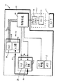
図1および図2は、媒体13上に印字する取り外し可能なインクのカートリッジ12を有する、インク・ジェット・プリント・システム10を示す。インクのカートリッジは、インクを充填したチャンバを規定するインク槽14、および、カートリッジのメモリチップ20を含むシャシ16を含む。プリンタは、4本の電線26を経由してカートリッジのチップ20に接続された制御装置24を取り囲むハウジング22を有する。ハウジングには、インクのレベルの表示装置30が搭載されており、図示のように制御装置に電気的に接続されている、あるいは、コンピュータのソフトウェアによってユーザのビデオ表示端末装置上に表示されてもよい。メモリ33および印字要素34を有するプリントヘッド32は、ハウジング内で媒体に隣接して往復運動をする。インク管35がインク供給容器をプリントヘッドに接続しており、印字用のインクを供給している。プリントヘッド制御バス36が、制御装置をプリントヘッドに電気的に接続しており、印字データをプリントヘッドに伝える。この図では、簡単のためにプリントヘッドもインクのカートリッジも単一であるように示しているが、好適な実施例はそれぞれの要素を4個有しており、そのそれぞれが特定のインクのカラー(ブラック、シアン、イエロー、マゼンタ)に対応する。プリンタ10に接続されたコンピュータ37は、制御装置24に接続されたプリンタのドライバ38、中央演算処理装置39、および接続されたモニタ41を含む。
【0008】
図3は、インクのカートリッジ12の構成要素14、16がどのようにプリンタ10に取り外し可能に接続可能かを示す。プリンタは、プリンタのハウジングに関して固定されておりインクのカートリッジを完全に収容する容器になっている、インク供給ステーション40の凹みを規定している。ステーションの凹みは床42を有しており、その上には、液体の相互接続44および電気的相互接続46が搭載されている。液体の相互接続には、中空のニードル52を取り囲む整列スリーブ50が含まれており、このニードルが、インク管35に接続する流路を規定している。詳細には図示していないが、ニードルには、インクのカートリッジが取り付けられていないときに湿度を保持する封入容器が設けられている。
【0009】
電気的相互接続は、横に延びるベント部を呈するように形成された4本のピン56を有する突出したボス54を含む。液体のおよび電気的相互接続は、互いから間隔をおいて配置されており、電気的コネクターが不用意に接触しインクが漏れることが防止されている。
【0010】
インクのカートリッジのシャシ部16は、図面の平面と平行な方向の平らな平面を有する、堅い長方形のシェルである。シャシの前縁(leading edge)60は、凹みの床42に向かって延びている。シャシは大部分中空である、というのも、チャンバの後縁(trailing edge)64で開いた槽のチャンバ62を規定しているからである。インク流路66は、整列スリーブ50と位置合わせされてそこに係合する、槽のチャンバ62から前縁60を通る開口部を規定している。シャシの前縁の、インク流路66から間隔をおいた位置には、ポケット70が規定されている。ポケットの一方の壁には、4個の別個の導電性の平らな導体を有するコネクタ72が、インクのカートリッジの平面と平行になるように搭載されている。これによって、カートリッジがインク供給ステーション40の凹みに挿入されるにつれてプリンタの相互接続のピンがそれぞれのパッドに沿ってこすっていき、パッドから酸化物(oxidation)やよごれを除去し、適切なオーム接触が保証される。シャシは、コネクタと一体であるまたはコネクタの下にある、4個のコネクタのパッドのそれぞれへの接続部を有する、メモリチップを含む。
【0011】
チャンバ62内の板ばねのリセットスイッチ74もまた、槽がチャンバ内に復位するとスイッチが閉じメモリ要素に接続されて、メモリ要素に信号を送る。または、インク槽を交換するときにユーザが手動で作動させるリセットスイッチ74’をシャシの外側に搭載することができる。
【0012】
インク槽14は、インクのチャンバを規定する平らな物体である。好ましくは、袋が、内容物が枯渇すると薄い平らな状態につぶれることができるのに十分な柔軟性を有している。または、インク槽14は、つぶれることができる袋を内部に有する、またはインクが消費されるときに外の大気と圧力を等しくすることができる弁のついた通気孔を有する、容易にシャシのチャンバ62に挿入および取り外しができる、薄く堅いシェルを有してもよい。槽の前縁において、インク出口76が、シャシのインク流路66とおよび液体の接続44のニードル52と位置合わせされた位置から突出している。インク出口の端面は、ニードルで貫くことができるセルフシールの隔壁によってシールされている。出口の外面は、インク流路66内にぴったりと収容されインク流路66に支持されるような形状になっており、カートリッジ全体がプリンタ内に取り付けられる間に位置合わせを行うようになっている。
【0013】
プリンタの制御装置24は、印字状況を記録し、それぞれのカートリッジからどれくらいのインクが消費されたかの推定値を維持するようにプログラムされている。本質的には、これは滴カウンタと考えてもよい。通常、カートリッジのシャシ上のメモリチップが、滴使用情報を記憶する役割を果たす。チップのメモリは、「インク充填」状態の値で始まってもよい。この値は、印字が進むにつれてデクリメントし、ついに「インク空」状態に達し、この状態に達すると、カートリッジが「インク充填」または中間状態を示すものと交換されるまで、プリンタは機能しなくなる。
【0014】
それぞれのカートリッジに関するこの情報を記憶することによって、使用情報を失うことなくカートリッジを取り外したり交換することができる。印字が進むにつれて、プリンタはカートリッジのメモリ上に記憶された使用情報を読み出し、対応する出力を表示装置30上に表示する。この出力は、棒グラフの形態であっても「ガス・ゲージ」の形態であってもよい。自動車における燃料計と異なり、かかる計器は槽内の現在の液体のレベルを感知する必要はないので、複雑なインクレベルセンサは必要ない。
【0015】
好適な実施例において、メモリチップはEEPROMであり、これは、インクの使用が進むにつれて書き込まれるまたはデクリメントされる。完全に枯渇すると、チップは、槽が交換されるときの板ばねスイッチ74の開放または再作動、またはスイッチ74’の手動での作動、のどちらかによって、リセットされねばならない。好適な実施例において、チップおよびコネクタは、電源、アース、クロック、および入力/出力の4本のラインを有する。チップは、書き込まれることのないMROMであってもよく、MROM、EPROM、およびEEPROMの部分を組み合わせたものを含んで標準チップの性能をエミュレートしてもよい。1実施例において、滴カウンタは8ビットの一回書き込みメモリー(write once memory)を有し、それぞれのビットはインク供給容器の8分の1に対応し、精密カウンタがカートリッジの容量の8分の1と同等のインク滴の量の使用を記録した後で、書き込むことができる。
【0016】
それぞれのカートリッジのメモリチップは、カートリッジの容積、製造日、製造年、有効期限、インクの保管寿命、および製品通し番号、等の工場で記録される情報を含んでもよい。メモリはまた、インクの化学および測色データ、およびインクの乾燥時間やガス抜け速度に関する情報を含み、カートリッジの寿命の間最適の印字ができるようにすることができる。チップにはまた、時々使用と共にプリンタが書き込む。かかる情報には、全容量の8分のいくつかで使用量を粗く表示したもの、精密な滴のカウント、最初の使用日、最新の使用日、使用中の持続時間、を含むことができる。
【0017】
好適な動作方法を図4に示す。印字の前には、プリンタの電源がオンにされ、プリンタのドライバおよびファームウェアが、それぞれのカートリッジのメモリチップからインクのレベルまたは滴の体積を読み取る。カートリッジがない場合には、プリンタは印字せず、ユーザにカートリッジを取り付けねばならないということを知らせることができる。異なるカートリッジが取り付けられる度に、カートリッジのメモリの内容がプリンタの制御装置に関連するキャシュメモリに読み込まれる。
【0018】
前もって互いに接続されているシャシと槽を取り付けた(110)状態で動作が開始する。ユーザは次に新しい印字ジョブを開始し(112)、プリンタはカートリッジのメモリチップに照会して(114)槽内のインクの量を確認する。制御装置は受け取ったデータに基づいてインクのレベルを計算し、表示装置に信号を送ってインクのレベルをユーザに示す(116)。制御装置は、インク供給容器が空かどうかを判断する(118)。
【0019】
インク供給容器が空でない場合には、プリンタは印字ジョブの一部を印字し(120)、その印字ステップの間のインクの使用を反映するようにメモリチップを更新する(122)。これには、カートリッジのメモリ上の精密カウンタへの書き込みを含んでもよく、精密カウンタがいっぱいになる場合には、粗いカウンタのビットの1つに書き込んで精密カウンタをゼロにリセットして次の印字に備えることを含んでもよい。プリンタは次に、印字ジョブが完了したかどうかを確認する(124)。完了した場合には、プリンタは停止し、新しい印字ジョブを開始する命令を待ち(126)、印字命令が来ると、ステップ112に進んで新しいジョブを開始する。印字ジョブの間、ジョブのそれぞれのシートの印字の最後において、制御装置はすべてのメモリ要素を読み込んで、インク供給容器を反映する表示装置を更新する。これによって、大量の印字ジョブの間も、ユーザはインクの消費を監視することができる。
【0020】
ステップ118でインク供給容器が空であると確認される場合には、プリンタは印字ジョブを一時停止し(128)、インクが空であるということを表示装置上に示す。印字を続行するためには、ユーザはインク槽を交換せ(130)ねばならない。好ましくは、これには、インクのカートリッジ全体を取り外し、その後シャシから枯渇した槽を取り外して充填した槽と交換することが含まれる。リセット信号を供給する(132)板ばねタイプのリセットスイッチがシャシにない場合には、ユーザがリセットボタンを手動で作動させる。その後カートリッジ全体がインク供給ステーションに取り付けられ、ニードルが隔壁を貫いてインクが流れるようになり、電気的コネクタがコネクタ上の4個のパッドのそれぞれと接触するようになる。他の方法では、ユーザは枯渇したインク槽を保持し、インクをニードルその他の手段で内部に注入することによってそのインク槽にインクを再補充してもよい。
【0021】
メモリチップをリセットすることによって、チップはインク枯渇データを消去するか、または残りのインクの量を反映するデータを再書き込みする。いずれにせよ、メモリは「インク充填」状態に相当する状態に戻り、印字が続行し、次の印字中に残りのインク量が適切に表示され更新される。リセットすることにより、粗いカウントおよび/または精密なカウントを変えること、または製造、有効日、および使用の日に関するその他の記録データを変えること、のどちらかを行うことができる。
【0022】
カートリッジが交換されると、印字ジョブが再開する(134)。
【0023】
他の代替印字動作を図5に示す。本実施例において、インクのカートリッジは、EEPROMの代わりにより簡単なROMのチップを有する。このチップは、プリンタに「インク充填」信号を常に供給するようにプログラムされており、プリンタがインクの枯渇のために運転停止しないようにしている。従って、プリンタがチップを調べてインク供給レベルをチェックする場合には、「全充填」信号を読み取り、インクのレベルを時々再チェックした後、全ジョブ、またはジョブの一部の印字(220)が続行される。本実施例において、プリンタはインク供給容器が空になるまで印字を続行するので、ユーザは、通常印字ページが適切に出力されているかを確認することによって、インクが槽内にあるかどうかを時々確認する(222)ことができる。インク供給容器が空の場合には(224)、ユーザはインク供給容器を交換(226)または再補充して新しい印字ジョブを開始することができる。供給容器が空でない場合には、交換なしに印字を続行することができる。
【0024】
図5の実施例の変形において、プリンタは、現在のレベルを確認して表示することをせずにカートリッジが空かどうかのみを感知する、といった、より簡単なレベルの検出過程を有することができる。かかるシステムにおいては、プリンタは、チップ出力の1つが所与の電圧レベルに維持されている間は印字し、出力電圧が異なるレベルに変わると印字を停止する。かかる応用例では、チップをカートリッジのシャシから省いて、アースまたは電圧入力のどちらかに配線によって接続されたコネクタの出力パッドが「インク充填」に対応する連続的な信号を供給するようにしてもよい。したがって、プリンタは滴の使用情報を書き込んでカウンタをデクリメントしようとするが、出力電圧は不変のままである。
【0025】
図4の実施例の代替案において、チップが、カウンタが空になるとインクのレベルを自動的にリセットする回路をさらに有してもよく、または、ユーザが、シャシを適当な再プログラミング信号を発生する別個の再プログラミング・ボックス(図示せず)に接続することによってかかるリセットを行ってもよい。
【0026】
また、耐用保管寿命を超えたインクで印字することを回避するためにチップ上のデート・コードを読み取るようにプログラムされたプリンタに対して印刷停止の信号をおくることを回避するために、すべての実施例においてリセット動作によってチップ内のデート情報をリセットすることができる。
【0027】
カートリッジの挿入の選択性を非常に高いレベルにプログラムしたプリンタでは、挿入されたカートリッジ内のチップに欠陥がないことを確認するエラー回路を設けてもよい。これには、チップのメモリの様々なセクタを読んだり、書いたり、および/または消去したり、それぞれのセクタが予想どおりに応答したことを確認するために読みこむ技術を用いることができる。かかるプリンタでは、カートリッジのメモリチップは、インクレベル状態を必要に応じてリセットする能力を保持しながら、必要な機能をエミュレートすることができる。
【0028】
さらに他の実施例において、単一のシャシおよび多数のインク槽、または、単一のシャシおよび単一の槽と、その槽を再補充する再補充ボトル、を含むキットを設けてもよい。どちらの実施例においても、動作は上述のように実行してもよく、または再充填ボトルの全内容のキット内のすべての槽の容積に等しい初期インク容積を示すようにプログラムされたチップを用いてもよい。したがって、インクレベル表示器は、単一の槽が交換または再補充を必要としても通知せず、キット全体が枯渇に達しようとすると知らせる。
【0029】
好適なおよび他の実施例に関して本発明を説明したが、添付の特許請求の範囲をこれに限定するように意図するものではない。
【0030】
以上、本発明の実施例について詳述したが、以下、本発明の各実施態様の例を示す。
【0031】
(実施態様1)
液体の相互接続(44)およびプリンタの電気的コネクタ(46)を有するインク供給ステーション(40)を有するインク・ジェット・プリント・システム(10)用の交換式のインクのカートリッジ(12)であって、該カートリッジ(12)は以下(a)および(b)を含むことを特徴とする、
(a)前記インク供給ステーションと取り外し可能に係合することができるシャシであって、該シャシは、インク流路(66)を規定し、前記プリンタの電気的コネクタと係合することができるカートリッジの電気的コネクタ(72)を含み、
(b)選択された量の供給インクを収容するチャンバを規定するインク槽(14)を含み、
前記インク槽は、前記インク流路と位置合わせされたインク出口(76)を有し、
前記シャシは、前記カートリッジの電気的コネクタに接続され、前記インク槽が枯渇して第2の槽と交換されたり、再補充されたり、別の槽に接続されるとき、第1の量よりもインクの全体量が多くなった後に印字を可能にする信号を発生するように動作可能な、インク・レベル・アナウンシエータ(20)を有する。
【0032】
(実施態様2)
実施態様1に記載の交換式のインクのカートリッジであって、該カートリッジは、前記アナウンシエータに接続されたリセットスイッチ(74)を含み、前記アナウンシエータが前記リセットスイッチの作動に応答して前記カートリッジがインクで充填されていることを示す信号を発生するように動作可能であることを特徴とする。
【0033】
(実施態様3)
実施態様1または実施態様2に記載の交換式のインクのカートリッジであって、該カートリッジは、前記アナウンシエータ(20)が、インクレベルに関係なく「インク充填」信号を発生するように動作可能であることを特徴とする。
【0034】
(実施態様4)
実施態様1から実施態様3のいずれかに記載の交換式のインクのカートリッジであって、該カートリッジは、前記シャシが、前記槽の少なくとも一部を収容するチャンバ(62)を規定することを特徴とする。
【0035】
(実施態様5)
実施態様1ないし実施態様4のいずれかに記載の交換式のインクのカートリッジであって、該カートリッジは、前記シャシおよび前記槽が一緒に、主要な平面を規定する平らで長方形の本体を含み、前記インク流路および前記電気的コネクタが、前記物体の共通の縁(60)に沿って互いに間隔をおいて配置されていることを特徴とする。
【0036】
(実施態様6)
実施態様1ないし実施態様5のいずれかに記載の交換式のインクのカートリッジであって、該カートリッジは、前記インク槽(14)が枯渇すると前記シャシ(16)を交換する必要なしに、交換できるように前記シャシに取り外し可能に接続されていることを特徴とする。
【0037】
(実施態様7)
カートリッジからのインクレベル信号に応答して動作可能なプリンタ(10)から取り外し可能なインク・ジェットのカートリッジ(12)の整備方法であって、該方法は以下(a)から(d)のステップを含むことを特徴とする、
(a)前記プリンタから前記カートリッジを取り外す(130)ステップ、
(b)前記カートリッジにインクを補充するステップ、
(c)前記カートリッジを前記プリンタ内に取り付けるステップ、および
(d)前記プリンタの動作を許可するインクレベル信号を発生する(132)ステップ。
【0038】
(実施態様8)
実施態様7に記載のインク・ジェットのカートリッジの整備方法であって、該方法は、インクレベル信号を発生する(132)前記ステップが、前記槽内のインクの量に関係なく「インク充填」信号を発生することを含むことを特徴とする。
【0039】
(実施態様9)
実施態様7または実施態様8に記載のインク・ジェットのカートリッジの整備方法であって、該方法は、インクレベル信号を発生する前記ステップが、連続的に「インク充填」信号を発生する(114)ことを含むことを特徴とする。
【0040】
(実施態様10)
実施態様7ないし実施態様9のいずれかに記載のインク・ジェットのカートリッジの整備方法であって、該方法は、前記シャシ上のインクレベルのスイッチをリセットする(132)ことを含むことを特徴とする。
【図面の簡単な説明】
【図1】本発明の好適な実施例によるプリンタの斜視図である。
【図2】図1の実施例の簡略ブロック図である。
【図3】図1の実施例の簡略分解断面図である。
【図4】図1の実施例の動作方法を示すフローチャートである。
【図5】図1の実施例の他の動作方法を示すフローチャートである。
【符号の説明】
10:インク・ジェット・プリント・システム
12:インク・カートリッジ
14:インク槽
16:シャシ
20:アナウンシエータ
40:インク供給ステーション
44:液体の相互接続
46:電気的相互接続
60:シャシの前縁
62:槽のチャンバ
66:インク流路
72:コネクタ
74:リセットスイッチ
76:インク出口[0001]
[Industrial application fields]
The present invention relates to an ink jet cartridge, and more particularly to a two-part ink jet cartridge having a separate ink supply container.
[0002]
[Prior art]
A typical ink jet printer has a pen that reciprocates on a printable surface such as paper. The pen includes a printhead having a series of multiple orifices through which ink drops can be ejected onto the surface to produce the desired pattern. Some ink jet printers have a replaceable ink supply container that is mounted in a stationary position on the printer and connected by a conduit to a reciprocating print head. This allows a larger ink supply container to be used and eliminates the need to replace the printhead each time the ink supply container is depleted. Color ink jet printers typically have a single cartridge with multiple chambers, or several ink supply cartridges, each containing a different color of ink.
[0003]
Some current systems provide electronic memory chips mounted on each of the stationary ink supply cartridges to exchange information about the contents of the cartridges. It is also possible for such a chip to act as a gas gauge that indicates the amount of ink remaining and communicates to the printer, preventing the printer from continuing printing with an empty cartridge. .
[0004]
Onboard memory in the ink cartridge also includes the date of manufacture (to ensure that too old ink does not damage the printhead), ink color (to prevent mis-installation), manufacturing identification code (compatibility Helped to record or store other information about the ink cartridge, such as to ensure that ink from a poor quality supplier does not enter and damage other parts of the printer Can be made.
[0005]
[Problems to be solved by the invention]
However, for very low cost applications, the cost of replacing a chip each time the cartridge is depleted may be greater than the benefits that a memory chip in each disposable cartridge provides. In addition, there may be other elements within the cartridge, such as structural, water supply and feed-in components, whose service life is much longer than the time it takes for the ink supply to deplete. However, with the current cartridge, even if the chip and the ink supply element are separated, simply replacing or refilling the ink supply does not enable the printer to operate. Because it may continue to indicate that the cartridge is depleted or has exceeded its shelf life and the print may refuse to continue to avoid the risk of damage or defective output. Thus, in a printer having a sensor that avoids using a depleted or old cartridge, a low cost ink jet that can hold the non-depleted element of the ink cartridge while recovering the ink supply container・ Need a print system.
[0006]
[Means for Solving the Problems]
The present invention overcomes or reduces the disadvantages of the prior art by providing a replaceable ink cartridge for an ink jet printer having an ink supply station having an ink container and an electrical connector. The cartridge includes a chassis that is removable from the ink supply station and has an ink passage and an electrical connector connectable to an electrical connector of the printer. An ink tank is detachably connected to the chassis, and the ink tank has a chamber containing the supply ink. The reservoir has an ink outlet aligned with the ink flow path, and the chassis is connected to the electrical connector of the cartridge and provides a signal that enables printing after the ink reservoir is depleted and replaced with a second reservoir. Has a generated ink level annunciator.
[0007]
DETAILED DESCRIPTION OF THE INVENTION
1 and 2 show an ink
[0008]
FIG. 3 shows how the
[0009]
The electrical interconnect includes a protruding
[0010]
The
[0011]
A leaf spring reset switch 74 in
[0012]
The
[0013]
The
[0014]
By storing this information for each cartridge, the cartridge can be removed and replaced without loss of usage information. As printing proceeds, the printer reads the usage information stored on the cartridge memory and displays the corresponding output on the
[0015]
In the preferred embodiment, the memory chip is an EEPROM, which is written or decremented as ink usage proceeds. When fully depleted, the chip must be reset either by opening or reactivating the leaf spring switch 74 when the vat is changed, or by manually actuating the switch 74 '. In the preferred embodiment, the chip and connector have four lines: power, ground, clock, and input / output. The chip may be a non-written MROM, and may include a combination of MROM, EPROM, and EEPROM portions to emulate the performance of a standard chip. In one embodiment, the drop counter has an 8-bit write once memory, each bit corresponding to one-eighth of the ink supply container, and the precision counter is one-eighth of the cartridge capacity. After recording the use of an ink drop volume equivalent to 1, it can be written.
[0016]
The memory chip of each cartridge may contain factory recorded information such as cartridge volume, date of manufacture, year of manufacture, expiration date, ink shelf life, and product serial number. The memory may also include ink chemistry and colorimetric data, and information regarding ink drying time and outgassing rate to allow for optimal printing over the life of the cartridge. The chip also writes from time to time with the printer. Such information may include a rough indication of usage at some eighth of the total volume, a precise drop count, first use date, last use date, duration in use.
[0017]
A preferred method of operation is shown in FIG. Prior to printing, the printer is turned on and the printer driver and firmware read the ink level or drop volume from the memory chip of the respective cartridge. If there is no cartridge, the printer does not print and can inform the user that the cartridge must be installed. Each time a different cartridge is installed, the contents of the cartridge memory is read into the cache memory associated with the printer controller.
[0018]
The operation starts with the chassis and the tub attached to each other in advance (110). The user then starts a new print job (112) and the printer queries the cartridge memory chip (114) to determine the amount of ink in the reservoir. The controller calculates the ink level based on the received data and sends a signal to the display device to indicate the ink level to the user (116). The controller determines whether the ink supply container is empty (118).
[0019]
If the ink supply container is not empty, the printer prints a portion of the print job (120) and updates the memory chip to reflect the ink usage during the printing step (122). This may include writing to a precision counter on the cartridge memory, and if the precision counter is full, write to one of the coarse counter bits and reset the precision counter to zero for the next print. It may include preparing for. The printer then checks whether the print job is complete (124). If completed, the printer stops, waits for a command to start a new print job (126), and when a print command comes, it proceeds to step 112 and starts a new job. During a print job, at the end of printing each sheet of the job, the controller reads all memory elements and updates the display device reflecting the ink supply. This allows the user to monitor ink consumption even during a large number of print jobs.
[0020]
If it is determined in
[0021]
By resetting the memory chip, the chip either erases the ink depletion data or rewrites data that reflects the amount of ink remaining. In any case, the memory returns to the state corresponding to the “ink filling” state, printing continues, and the remaining ink amount is appropriately displayed and updated during the next printing. By resetting, either the coarse count and / or the fine count can be changed, or other recorded data regarding the date of manufacture, effective date, and date of use can be changed.
[0022]
When the cartridge is replaced, the print job is resumed (134).
[0023]
Another alternative printing operation is shown in FIG. In this embodiment, the ink cartridge has a simpler ROM chip instead of an EEPROM. This chip is programmed to always supply an “ink filling” signal to the printer, preventing the printer from shutting down due to ink depletion. Therefore, if the printer checks the chip to check the ink supply level, it reads the “full fill” signal and occasionally rechecks the ink level before printing (220) all jobs or part of a job. Continued. In this embodiment, the printer continues printing until the ink supply container is empty, so that the user sometimes checks whether the ink is in the tank by checking whether the normal print page is properly output. It can be confirmed (222). If the ink supply is empty (224), the user can replace (226) or refill the ink supply and start a new print job. If the supply container is not empty, printing can continue without replacement.
[0024]
In a variation of the embodiment of FIG. 5, the printer can have a simpler level detection process, such as sensing only whether the cartridge is empty without checking and displaying the current level. . In such a system, the printer prints while one of the chip outputs is maintained at a given voltage level and stops printing when the output voltage changes to a different level. In such an application, the chip may be omitted from the cartridge chassis so that the output pad of the connector connected by wiring to either ground or voltage input provides a continuous signal corresponding to “ink filling”. Good. Thus, the printer attempts to decrement the counter by writing drop usage information, but the output voltage remains unchanged.
[0025]
In the alternative to the embodiment of FIG. 4, the chip may further have circuitry that automatically resets the ink level when the counter is empty, or the user generates a suitable reprogramming signal to the chassis. Such a reset may be performed by connecting to a separate reprogramming box (not shown).
[0026]
Also, to avoid printing with ink that has exceeded its shelf life, to avoid sending a print stop signal to a printer programmed to read the date code on the chip, In the embodiment, the date information in the chip can be reset by a reset operation.
[0027]
In a printer where the cartridge insertion selectivity is programmed to a very high level, an error circuit may be provided to confirm that the chips in the inserted cartridge are free of defects. This can use techniques that read, write, and / or erase various sectors of the chip's memory and read to verify that each sector responded as expected. In such a printer, the memory chip of the cartridge can emulate the necessary functions while retaining the ability to reset the ink level state as needed.
[0028]
In still other embodiments, a kit may be provided that includes a single chassis and multiple ink reservoirs, or a single chassis and single reservoir and a refill bottle that refills the reservoir. In either embodiment, the operation may be performed as described above, or using a chip programmed to show an initial ink volume equal to the volume of all tanks in the full kit of refill bottles. May be. Thus, the ink level indicator does not notify if a single tank needs to be replaced or refilled, but notifies when the entire kit is about to run out.
[0029]
Although the invention has been described in terms of preferred and other embodiments, it is not intended to limit the scope of the appended claims.
[0030]
As mentioned above, although the Example of this invention was explained in full detail, the example of each embodiment of this invention is shown below.
[0031]
(Embodiment 1)
A replaceable ink cartridge (12) for an ink jet printing system (10) having an ink supply station (40) having a liquid interconnect (44) and a printer electrical connector (46). The cartridge (12) includes the following (a) and (b):
(A) A chassis that can be removably engaged with the ink supply station, the chassis defining an ink flow path (66) and a cartridge that can engage with an electrical connector of the printer. Electrical connector (72)
(B) including an ink reservoir (14) defining a chamber containing a selected amount of supply ink;
The ink reservoir has an ink outlet (76) aligned with the ink flow path;
The chassis is connected to the electrical connector of the cartridge, and when the ink tank is depleted and replaced with a second tank, refilled, or connected to another tank, it is more than the first amount. An ink level annunciator (20) operable to generate a signal that enables printing after the total amount of ink has increased.
[0032]
(Embodiment 2)
2. The replaceable ink cartridge of embodiment 1, wherein the cartridge includes a reset switch (74) connected to the annunciator, wherein the annunciator is responsive to actuation of the reset switch. The cartridge is operable to generate a signal indicating that the cartridge is filled with ink.
[0033]
(Embodiment 3)
3. A replaceable ink cartridge according to embodiment 1 or embodiment 2, wherein the cartridge is operable such that the annunciator (20) generates an “ink fill” signal regardless of ink level. It is characterized by being.
[0034]
(Embodiment 4)
Embodiment 4 A replaceable ink cartridge according to any of embodiments 1 to 3, wherein the chassis defines a chamber (62) in which the chassis houses at least a portion of the reservoir. And
[0035]
(Embodiment 5)
Embodiment 5. A replaceable ink cartridge according to any of embodiments 1 to 4, wherein the cartridge and the tank together comprise a flat, rectangular body defining a major plane, The ink flow path and the electrical connector are spaced apart from each other along a common edge (60) of the object.
[0036]
(Embodiment 6)
Embodiment 6. The replaceable ink cartridge according to any of embodiments 1 to 5, wherein the cartridge can be replaced without the need to replace the chassis (16) when the ink reservoir (14) is depleted. As described above, it is removably connected to the chassis.
[0037]
(Embodiment 7)
A method for servicing an ink jet cartridge (12) removable from a printer (10) operable in response to an ink level signal from the cartridge comprising the steps of (a) to (d) below: Including,
(A) removing the cartridge from the printer (130);
(B) replenishing the cartridge with ink;
(C) mounting the cartridge in the printer; and (d) generating an ink level signal that permits operation of the printer (132).
[0038]
(Embodiment 8)
An ink jet cartridge servicing method according to embodiment 7, wherein the method generates an ink level signal (132), wherein the step is an "ink filling" signal regardless of the amount of ink in the reservoir. Generating.
[0039]
(Embodiment 9)
9. An ink jet cartridge servicing method according to embodiment 7 or embodiment 8, wherein said step of generating an ink level signal continuously generates an "ink fill" signal (114). It is characterized by including.
[0040]
(Embodiment 10)
[Brief description of the drawings]
FIG. 1 is a perspective view of a printer according to a preferred embodiment of the present invention.
FIG. 2 is a simplified block diagram of the embodiment of FIG.
FIG. 3 is a simplified exploded cross-sectional view of the embodiment of FIG.
FIG. 4 is a flowchart showing an operation method of the embodiment of FIG. 1;
FIG. 5 is a flowchart showing another operation method of the embodiment of FIG. 1;
[Explanation of symbols]
10: ink jet print system 12: ink cartridge 14: ink reservoir 16: chassis 20: annunciator 40: ink supply station 44: liquid interconnect 46: electrical interconnect 60: chassis leading edge 62 : Tank chamber 66: ink flow path 72: connector 74: reset switch 76: ink outlet
Claims (8)
該カートリッジ(12)は、
前記インク供給ステーション(40)と取り外し可能に係合することができ、かつ、インク流路(66)を規定し、前記プリンタの電気的コネクタ(46)と係合することができるカートリッジの電気的コネクタ(72)を含むシャシ(16)と、
選択された量の供給インクを収容するチャンバを規定するインク槽(14)とを含み、
前記インク槽(14)は、前記インク流路(66)と位置合わせされたインク出口(76)を有し、
前記シャシ(16)は、前記カートリッジ(12)の電気的コネクタ(72)に接続され、前記インク槽(14)が枯渇して第2のインク槽と交換されたり、再補充されたり、別のインク槽に接続されるとき、第1の量よりもインクの全体量が多くなった後にプリントを可能にする信号を発生するように動作可能な、インク・レベル・アナウンシエータ(20)を有することを含み、
前記カートリッジ(12)は、前記インク槽(14)が枯渇して第2のインク槽と交換されたり、再補充されたり、別のインク槽に接続されるとき、第1の量よりもインクの全体量が多くなった後に、前記アナウンシエータ(20)が、前記インク槽(14)の現在のインクレベルに関係なく「インク充填」信号を発生するように動作可能であることを特徴とする
インク・ジェット・プリント・システム用の交換式のインクのカートリッジ。A replaceable ink cartridge (12) for an ink jet printing system (10) having an ink supply station (40) having a liquid interconnect (44) and an electrical connector (46) for the printer. And
The cartridge (12)
An electrical cartridge that can be removably engaged with the ink supply station (40) and that defines an ink flow path (66) and can be engaged with the electrical connector (46) of the printer. A chassis (16) including a connector (72);
An ink reservoir (14) defining a chamber containing a selected amount of supply ink;
The ink reservoir (14) has an ink outlet (76) aligned with the ink flow path (66),
The chassis (16) is connected to the electrical connector (72) of the cartridge (12), and the ink tank (14) is depleted and replaced with a second ink tank, or refilled. When connected to the ink reservoir, it has an ink level annunciator (20) operable to generate a signal that enables printing after the total amount of ink is greater than the first amount. Including
The cartridge (12) has more ink than the first amount when the ink reservoir (14) is depleted and replaced with a second ink reservoir, refilled, or connected to another ink reservoir. After the total volume has increased, the annunciator (20) is operable to generate an “ink filling” signal regardless of the current ink level in the ink reservoir (14). <br/> Replaceable ink cartridges for ink jet printing systems.
(a)前記プリンタ(10)から前記カートリッジ(12)を取り外す(130)ステップ、
(b)前記カートリッジ(12)にインクを補充するステップ、
(c)前記カートリッジ(12)を前記プリンタ(10)内に取り付けるステップ、
(d)前記プリンタ(10)の動作を許可するインクレベル信号を発生するステップ(132)を含み、
前記インク槽(14)が枯渇して第2のインク槽と交換されたり、再補充されたり、別のインク槽に接続されるとき、第1の量よりもインクの全体量が多くなった後に、インクレ ベル信号を発生する前記ステップ(132)が、前記インク槽(14)の現在のインクレベルに関係なく「インク充填」信号を発生することを含むことを特徴とするインク・ジェットのカートリッジの整備方法。 A method of servicing an ink jet cartridge (12) removable from a printer (10) operable in response to an ink level signal from a cartridge (12) having an ink reservoir (14) and a chassis (16). ,
(A) removing (130) the cartridge (12) from the printer (10) ;
(B) replenishing the cartridge (12) with ink;
(C) mounting the cartridge (12) in the printer (10) ;
(D) viewing including the step (132) for generating an ink level signal to permit operation of said printer (10),
When the ink reservoir (14) is depleted and replaced with a second ink reservoir, refilled, or connected to another ink reservoir, after the total amount of ink is greater than the first amount said step of generating a incremental bell signal (132) is an ink-jet cartridge, characterized in that it includes generating the "ink filling" signal regardless of the current ink level in the ink reservoir (14) Maintenance method.
Applications Claiming Priority (2)
| Application Number | Priority Date | Filing Date | Title |
|---|---|---|---|
| US785,103 | 1997-01-21 | ||
| US08/785,103 US5860363A (en) | 1997-01-21 | 1997-01-21 | Ink jet cartridge with separately replaceable ink reservoir |
Publications (2)
| Publication Number | Publication Date |
|---|---|
| JPH10202900A JPH10202900A (en) | 1998-08-04 |
| JP4093623B2 true JP4093623B2 (en) | 2008-06-04 |
Family
ID=25134452
Family Applications (1)
| Application Number | Title | Priority Date | Filing Date |
|---|---|---|---|
| JP00855398A Expired - Fee Related JP4093623B2 (en) | 1997-01-21 | 1998-01-20 | Printer cartridge having replaceable ink container |
Country Status (5)
| Country | Link |
|---|---|
| US (1) | US5860363A (en) |
| EP (1) | EP0854045B1 (en) |
| JP (1) | JP4093623B2 (en) |
| KR (1) | KR100556001B1 (en) |
| DE (1) | DE69703023T2 (en) |
Families Citing this family (113)
| Publication number | Priority date | Publication date | Assignee | Title |
|---|---|---|---|---|
| US6203147B1 (en) * | 1994-12-22 | 2001-03-20 | Hewlett-Packard Company | Electrical and fluidic interface for an ink supply |
| US6170937B1 (en) * | 1997-01-21 | 2001-01-09 | Hewlett-Packard Company | Ink container refurbishment method |
| US6168262B1 (en) * | 1997-01-30 | 2001-01-02 | Hewlett-Packard Company | Electrical interconnect for replaceable ink containers |
| US6786420B1 (en) | 1997-07-15 | 2004-09-07 | Silverbrook Research Pty. Ltd. | Data distribution mechanism in the form of ink dots on cards |
| US6010210A (en) * | 1997-06-04 | 2000-01-04 | Hewlett-Packard Company | Ink container having a multiple function chassis |
| US6644771B1 (en) * | 1997-07-12 | 2003-11-11 | Silverbrook Research Pty Ltd | Printing cartridge with radio frequency identification |
| US6547364B2 (en) | 1997-07-12 | 2003-04-15 | Silverbrook Research Pty Ltd | Printing cartridge with an integrated circuit device |
| US6618117B2 (en) | 1997-07-12 | 2003-09-09 | Silverbrook Research Pty Ltd | Image sensing apparatus including a microcontroller |
| US6879341B1 (en) | 1997-07-15 | 2005-04-12 | Silverbrook Research Pty Ltd | Digital camera system containing a VLIW vector processor |
| US20040119829A1 (en) * | 1997-07-15 | 2004-06-24 | Silverbrook Research Pty Ltd | Printhead assembly for a print on demand digital camera system |
| US6690419B1 (en) * | 1997-07-15 | 2004-02-10 | Silverbrook Research Pty Ltd | Utilising eye detection methods for image processing in a digital image camera |
| US7325897B2 (en) * | 1997-07-15 | 2008-02-05 | Silverbrook Research Pty Ltd | Printing cartridge with pressure sensor array identification |
| US7110024B1 (en) | 1997-07-15 | 2006-09-19 | Silverbrook Research Pty Ltd | Digital camera system having motion deblurring means |
| AUPO850597A0 (en) * | 1997-08-11 | 1997-09-04 | Silverbrook Research Pty Ltd | Image processing method and apparatus (art01a) |
| US6985207B2 (en) * | 1997-07-15 | 2006-01-10 | Silverbrook Research Pty Ltd | Photographic prints having magnetically recordable media |
| AUPO802797A0 (en) * | 1997-07-15 | 1997-08-07 | Silverbrook Research Pty Ltd | Image processing method and apparatus (ART54) |
| US6624848B1 (en) | 1997-07-15 | 2003-09-23 | Silverbrook Research Pty Ltd | Cascading image modification using multiple digital cameras incorporating image processing |
| US6024429A (en) * | 1997-10-30 | 2000-02-15 | Pitney Bowes Inc. | Mailing machine including ink jet printing having ink availability checking |
| JPH11334104A (en) * | 1998-05-26 | 1999-12-07 | Toshiba Tec Corp | Ink-jet printer |
| AUPP702098A0 (en) | 1998-11-09 | 1998-12-03 | Silverbrook Research Pty Ltd | Image creation method and apparatus (ART73) |
| MY138350A (en) * | 1998-11-02 | 2009-05-29 | Seiko Epson Corp | Ink cartridge and printer using the same |
| JP2000218818A (en) * | 1998-11-26 | 2000-08-08 | Seiko Epson Corp | Ink container and printer using the same |
| JP2001187457A (en) * | 1998-11-26 | 2001-07-10 | Seiko Epson Corp | Printing device and cartridge |
| US7344325B2 (en) * | 1999-01-25 | 2008-03-18 | Fargo Electronics, Inc. | Identification card printer having ribbon cartridge with cleaner roller |
| USD428915S (en) * | 1999-02-03 | 2000-08-01 | Hewlett-Packard Company | Fluid container cap |
| USD428437S (en) * | 1999-02-03 | 2000-07-18 | Hewlett-Packard Company | Fluid container |
| USD428438S (en) * | 1999-02-03 | 2000-07-18 | Hewlett-Packard Company | Fluid container cap |
| US6493018B1 (en) | 1999-04-08 | 2002-12-10 | Gerber Scientific Products, Inc. | Wide format thermal printer |
| US6106166A (en) * | 1999-04-16 | 2000-08-22 | Eastman Kodak Company | Photoprocessing apparatus for sensing type of photoprocessing consumable and method of assembling the apparatus |
| AUPQ056099A0 (en) * | 1999-05-25 | 1999-06-17 | Silverbrook Research Pty Ltd | A method and apparatus (pprint01) |
| US6644544B1 (en) | 1999-06-16 | 2003-11-11 | Eastman Kodak Company | Imaging apparatus capable of forming an image consistent with type of imaging consumable loaded therein and method of assembling the apparatus |
| US6658219B1 (en) * | 1999-09-30 | 2003-12-02 | Fuji Photo Film Co., Ltd. | Method, device, system and recording medium for detecting improper cartridge, and cartridge |
| US7048348B2 (en) | 2000-10-17 | 2006-05-23 | Seiko Epson Corporation | Ink bag recording apparatus incorporating the same |
| JP3546870B2 (en) * | 2000-10-17 | 2004-07-28 | セイコーエプソン株式会社 | Ink storage bag and recording device for mounting the same |
| US6467888B2 (en) | 2001-02-21 | 2002-10-22 | Illinois Tool Works Inc. | Intelligent fluid delivery system for a fluid jet printing system |
| AU2005200191B2 (en) * | 2001-08-06 | 2005-10-20 | Zamtec Limited | Printing control based on radio frequency identification of printing cartridge |
| US20050162455A1 (en) * | 2001-08-06 | 2005-07-28 | Kia Silverbrook | Printing cartridge with an integrated circuit device |
| US6505926B1 (en) | 2001-08-16 | 2003-01-14 | Eastman Kodak Company | Ink cartridge with memory chip and method of assembling |
| US6805842B1 (en) * | 2001-10-12 | 2004-10-19 | Mds Sciex | Repuncturable self-sealing sample container with internal collapsible bag |
| US6536886B1 (en) * | 2001-10-29 | 2003-03-25 | Hewlett-Packard Company | Reservoir integration for multi-part inkjet printing system, and method |
| US6705713B2 (en) | 2002-07-18 | 2004-03-16 | Eastman Kodak Company | Disposable ink assemblage |
| US6702435B2 (en) | 2002-07-18 | 2004-03-09 | Eastman Kodak Company | Ink cartridge having ink identifier oriented to provide ink identification |
| US6712459B2 (en) | 2002-07-18 | 2004-03-30 | Eastman Kodak Company | Ink cartridge having shielded pocket for memory chip |
| US6715864B2 (en) | 2002-07-18 | 2004-04-06 | Eastman Kodak Company | Disposable ink supply bag having connector-fitting |
| US20040012660A1 (en) * | 2002-07-18 | 2004-01-22 | Eastman Kodak Company | Ink cartridge having connectable-disconnectable housing and ink supply bag |
| US6709093B2 (en) | 2002-08-08 | 2004-03-23 | Eastman Kodak Company | Ink cartridge in which ink supply bag held fast to housing |
| US6755501B2 (en) | 2002-08-08 | 2004-06-29 | Eastman Kodak Company | Alternative ink/cleaner cartridge |
| US6830323B2 (en) | 2002-08-13 | 2004-12-14 | Eastman Kodak Company | Restricting flash spread when welding housing halves of cartridge together |
| US6837576B2 (en) | 2002-08-21 | 2005-01-04 | Eastman Kodak Company | Method of filling ink supply bag for ink cartridge |
| US6705714B1 (en) | 2002-08-21 | 2004-03-16 | Eastman Kodak Company | Ink cartridge having ink supply bag filled to less than capacity and folded in cartridge housing |
| JP4133154B2 (en) | 2002-09-19 | 2008-08-13 | 株式会社リコー | Ink cartridge and inkjet printer |
| JP4175065B2 (en) | 2002-09-24 | 2008-11-05 | セイコーエプソン株式会社 | Cartridge, printing apparatus, and method for exchanging information with cartridge |
| JP4536358B2 (en) | 2002-12-04 | 2010-09-01 | 株式会社リコー | Image forming apparatus |
| JP3919734B2 (en) * | 2002-12-06 | 2007-05-30 | 株式会社リコー | Ink cartridge, casing thereof, and image forming apparatus |
| EP1603752B1 (en) | 2003-03-18 | 2010-11-03 | Ricoh Company, Ltd. | Ink bag and ink cartridge comprising the ink bag |
| JP4204373B2 (en) | 2003-04-18 | 2009-01-07 | 株式会社リコー | Liquid container bag, liquid cartridge, image forming apparatus, liquid container bag sealing method, and sealing device |
| US9296214B2 (en) | 2004-07-02 | 2016-03-29 | Zih Corp. | Thermal print head usage monitor and method for using the monitor |
| MX2007006388A (en) * | 2004-11-30 | 2007-06-20 | Panduit Corp | Market-based labeling system and method. |
| JP4047328B2 (en) * | 2004-12-24 | 2008-02-13 | キヤノン株式会社 | Liquid storage container, liquid supply system and recording apparatus using the container, and circuit board for the container |
| US8721203B2 (en) * | 2005-10-06 | 2014-05-13 | Zih Corp. | Memory system and method for consumables of a printer |
| DE102006036716B3 (en) * | 2006-06-02 | 2007-09-27 | Artech Gmbh Design + Production In Plastic | Printer e.g. inkjet printer, retrofitting device, has cartridge retaining device to retain replaceable original ink cartridges, and locking pin to lock fastener in fastening position when insert-ink cartridge is attached in retaining device |
| ATE492401T1 (en) | 2006-09-27 | 2011-01-15 | Ninestar Man Co Ltd | INK CARTRIDGE HOLDER FOR PRINT EQUIPMENT HOLDER |
| US20080165214A1 (en) * | 2007-01-05 | 2008-07-10 | Kenneth Yuen | Ink cartridge fluid flow arrangements and methods |
| US20080204528A1 (en) * | 2007-02-28 | 2008-08-28 | Kenneth Yuen | Ink cartridge |
| GB0720289D0 (en) | 2007-10-12 | 2007-11-28 | Videojet Technologies Inc | Ink jet printer |
| GB0720290D0 (en) * | 2007-10-12 | 2007-11-28 | Videojet Technologies Inc | Ink jet printer |
| GB0720139D0 (en) * | 2007-10-12 | 2007-11-28 | Videojet Technologies Inc | Ink jet printing |
| JP5146365B2 (en) * | 2008-03-13 | 2013-02-20 | セイコーエプソン株式会社 | How to change liquid container, substrate, liquid information |
| JP5206506B2 (en) * | 2008-03-13 | 2013-06-12 | セイコーエプソン株式会社 | Mounting device, substrate, and method for changing liquid information |
| JP5083250B2 (en) * | 2008-03-13 | 2012-11-28 | セイコーエプソン株式会社 | How to change liquid container, substrate, liquid information |
| JP2010012602A (en) * | 2008-06-30 | 2010-01-21 | Brother Ind Ltd | Package and ink cartridge |
| CN102161278B (en) * | 2008-06-30 | 2014-03-05 | 兄弟工业株式会社 | Adaptor for ink cartridge |
| JP5306140B2 (en) | 2008-12-19 | 2013-10-02 | キヤノン株式会社 | Liquid ejection device |
| JP5353565B2 (en) * | 2009-03-17 | 2013-11-27 | 株式会社リコー | Liquid container and image forming apparatus |
| CN101518991B (en) * | 2009-03-30 | 2012-02-15 | 珠海纳思达电子科技有限公司 | Adapter for ink-jet printer and ink box matched with same |
| KR200453209Y1 (en) * | 2009-03-31 | 2011-04-15 | 주식회사 알파켐 | Continuous Ink Supply System for Large Ink-jet Printer |
| CN101885270B (en) * | 2009-05-13 | 2012-09-05 | 珠海纳思达企业管理有限公司 | Adaptor on ink-jet printer and ink box matched with same |
| BRPI0924011B1 (en) | 2009-05-18 | 2021-06-01 | Hewlett-Packard Development Company, L.P. | APPARATUS AND APPARATUS OPERATION METHOD |
| JP5316326B2 (en) * | 2009-09-04 | 2013-10-16 | 株式会社リコー | Liquid container, method for assembling liquid container, method for disassembling liquid container, and image forming apparatus |
| TW201114613A (en) * | 2009-10-29 | 2011-05-01 | Fieldct Inc | Ink cartridge compatible with jet painting machine |
| CN101817258B (en) * | 2010-02-11 | 2012-02-29 | 孙荣华 | Novel ink-jet printing system and matched ink cartridge thereof |
| US8740325B2 (en) | 2010-12-13 | 2014-06-03 | Xerox Corporation | Method for printing in a printer having an inoperable ink reservoir |
| KR101139890B1 (en) * | 2011-10-28 | 2012-05-02 | 주식회사 디젠 | Ink cartridge device for digital printer |
| JP5948833B2 (en) * | 2011-12-08 | 2016-07-06 | セイコーエプソン株式会社 | Liquid supply system and liquid consumption apparatus |
| JP6044068B2 (en) * | 2011-12-14 | 2016-12-14 | セイコーエプソン株式会社 | Recording device |
| JP5998471B2 (en) * | 2011-12-20 | 2016-09-28 | セイコーエプソン株式会社 | adapter |
| KR101174295B1 (en) * | 2012-03-29 | 2012-08-16 | (주)나이테산기개발 | Apparatus of supplying ink for printer |
| JP6019697B2 (en) * | 2012-04-19 | 2016-11-02 | ブラザー工業株式会社 | Printing fluid storage device and printing fluid supply device |
| JP5978863B2 (en) * | 2012-08-31 | 2016-08-24 | セイコーエプソン株式会社 | Control unit |
| US8708470B1 (en) * | 2012-11-29 | 2014-04-29 | Videojet Technologies Inc. | Ink system |
| JP6163890B2 (en) | 2013-06-06 | 2017-07-19 | セイコーエプソン株式会社 | Liquid supply device, liquid container |
| RU2018135666A (en) | 2013-06-06 | 2018-11-19 | Сейко Эпсон Корпорейшн | LIQUID CONTAINER |
| US11265444B2 (en) * | 2013-08-23 | 2022-03-01 | Preemadonna Inc. | Apparatus for applying coating to nails |
| US9687059B2 (en) | 2013-08-23 | 2017-06-27 | Preemadonna Inc. | Nail decorating apparatus |
| US9855755B2 (en) | 2014-03-14 | 2018-01-02 | Seiko Epson Corporation | Liquid supply set, liquid supply apparatus, and liquid ejection system |
| US9821561B2 (en) * | 2014-03-14 | 2017-11-21 | Seiko Epson Corporation | Liquid supply set, liquid supply apparatus, and liquid ejection system |
| EP3118002B1 (en) | 2014-03-14 | 2020-06-03 | Seiko Epson Corporation | Liquid-accommodating body |
| US9821560B2 (en) | 2014-03-14 | 2017-11-21 | Seiko Epson Corporation | Liquid supply set, liquid supply apparatus, and liquid ejection system |
| WO2016141246A2 (en) | 2015-03-03 | 2016-09-09 | Stark N Daniel W | Pile for tower foundation |
| GB201608285D0 (en) | 2016-05-11 | 2016-06-22 | Videojet Technologies Inc | Printing |
| WO2018013125A1 (en) | 2016-07-14 | 2018-01-18 | Hewlett-Packard Development Company, L.P. | Fluid level sensing independent of write command |
| JP6834517B2 (en) * | 2017-01-20 | 2021-02-24 | ブラザー工業株式会社 | Inkjet recording device |
| WO2019070886A1 (en) | 2017-10-04 | 2019-04-11 | Preemadonna Inc. | Systems and methods of adaptive nail printing and collaborative beauty platform hosting |
| US11198299B2 (en) | 2018-07-13 | 2021-12-14 | Hewlett-Packard Development Company, L.P. | Collar for fluid barrier |
| CN112041173B (en) | 2018-07-13 | 2022-03-08 | 惠普发展公司,有限责任合伙企业 | Coupling system |
| CN112055658B (en) | 2018-07-13 | 2022-06-21 | 惠普发展公司,有限责任合伙企业 | Clamping plate with wedge-shaped fork end for printing liquid supply source |
| EP3820707A4 (en) * | 2018-07-13 | 2022-03-02 | Hewlett-Packard Development Company, L.P. | Fluid extraction via removable extraction reservoirs |
| EP4129699A1 (en) | 2018-07-13 | 2023-02-08 | Hewlett-Packard Development Company L.P. | Spouts with angled clamp flanges for a print liquid supply |
| CN112423989B (en) | 2018-07-13 | 2022-08-02 | 惠普发展公司,有限责任合伙企业 | Flexible printing liquid supply reservoir with offset nozzles |
| CN110103591B (en) * | 2019-06-13 | 2020-03-27 | 杭州旗捷科技有限公司 | Automatic resetting method of consumable chip and consumable chip |
| WO2021080604A1 (en) | 2019-10-25 | 2021-04-29 | Hewlett-Packard Development Company, L.P. | Logic circuitry package |
| KR20220006275A (en) * | 2020-07-08 | 2022-01-17 | 휴렛-팩커드 디벨롭먼트 컴퍼니, 엘.피. | toner cartridge having front cover |
| WO2022163803A1 (en) | 2021-01-29 | 2022-08-04 | ブラザー工業株式会社 | Image forming device, initialization method, and control method |
Family Cites Families (19)
| Publication number | Priority date | Publication date | Assignee | Title |
|---|---|---|---|---|
| DE3446998A1 (en) * | 1983-12-26 | 1985-07-04 | Canon K.K., Tokio/Tokyo | INK-JET RECORDING DEVICE |
| JPS60172546A (en) * | 1984-02-20 | 1985-09-06 | Konishiroku Photo Ind Co Ltd | Ink residue detector |
| US4568954A (en) * | 1984-12-06 | 1986-02-04 | Tektronix, Inc. | Ink cartridge manufacturing method and apparatus |
| JPH082649B2 (en) * | 1986-12-12 | 1996-01-17 | キヤノン株式会社 | Ink jet printer |
| JP2575205B2 (en) * | 1989-01-13 | 1997-01-22 | キヤノン株式会社 | Ink tank |
| US5049898A (en) * | 1989-03-20 | 1991-09-17 | Hewlett-Packard Company | Printhead having memory element |
| DE69033928T2 (en) * | 1989-08-05 | 2002-07-18 | Canon Kk | Ink jet recording apparatus and ink cartridge therefor |
| JPH03227629A (en) * | 1990-02-02 | 1991-10-08 | Canon Inc | Ink jet recorder |
| JP3222454B2 (en) * | 1990-02-02 | 2001-10-29 | キヤノン株式会社 | Ink tank cartridge |
| JP2584879B2 (en) * | 1990-02-23 | 1997-02-26 | キヤノン株式会社 | Facsimile machine |
| DE69130301T2 (en) * | 1990-02-26 | 1999-04-08 | Canon Kk | Ink recorder and method |
| JP2962044B2 (en) * | 1992-05-29 | 1999-10-12 | 富士ゼロックス株式会社 | Ink tank, inkjet cartridge, and inkjet recording device |
| IT1256844B (en) * | 1992-06-08 | 1995-12-21 | Olivetti & Co Spa | METHOD AND DEVICE FOR THE RECOGNITION OF THE END-INK IN AN INK-JET PRINT HEAD. |
| US5473350A (en) * | 1992-08-06 | 1995-12-05 | Scitex Digital Printing, Inc. | System and method for maintaining ink concentration in a system |
| US5675367A (en) * | 1992-12-23 | 1997-10-07 | Hewlett-Packard Company | Inkjet print cartridge having handle which incorporates an ink fill port |
| JPH07323645A (en) * | 1994-05-31 | 1995-12-12 | Canon Inc | Recording apparatus |
| US5610635A (en) * | 1994-08-09 | 1997-03-11 | Encad, Inc. | Printer ink cartridge with memory storage capacity |
| AU3241795A (en) * | 1994-08-09 | 1996-03-07 | Encad, Inc. | Printer ink cartridge |
| CA2164536A1 (en) * | 1995-01-03 | 1996-07-04 | William G. Hawkins | Ink supply identification system |
-
1997
- 1997-01-21 US US08/785,103 patent/US5860363A/en not_active Expired - Lifetime
- 1997-12-15 EP EP97310113A patent/EP0854045B1/en not_active Expired - Lifetime
- 1997-12-15 DE DE69703023T patent/DE69703023T2/en not_active Expired - Lifetime
-
1998
- 1998-01-20 JP JP00855398A patent/JP4093623B2/en not_active Expired - Fee Related
- 1998-01-20 KR KR1019980001524A patent/KR100556001B1/en not_active IP Right Cessation
Also Published As
| Publication number | Publication date |
|---|---|
| EP0854045A2 (en) | 1998-07-22 |
| US5860363A (en) | 1999-01-19 |
| DE69703023D1 (en) | 2000-10-12 |
| KR100556001B1 (en) | 2006-04-21 |
| KR19980070630A (en) | 1998-10-26 |
| EP0854045A3 (en) | 1998-12-02 |
| DE69703023T2 (en) | 2001-01-11 |
| JPH10202900A (en) | 1998-08-04 |
| EP0854045B1 (en) | 2000-09-06 |
Similar Documents
| Publication | Publication Date | Title |
|---|---|---|
| JP4093623B2 (en) | Printer cartridge having replaceable ink container | |
| JP4088353B2 (en) | Ink supply container | |
| KR100556000B1 (en) | Ink jet cartridge with ink level detection | |
| US6065824A (en) | Method and apparatus for storing information on a replaceable ink container | |
| JP4210034B2 (en) | System for renewing ink containers | |
| AU771461B2 (en) | Ink cartridge and printer using the same | |
| US6089687A (en) | Method and apparatus for specifying ink volume in an ink container | |
| US6533383B1 (en) | Ink jet type printing apparatus ink cartridge therefor and method of controlling the printing apparatus | |
| CN101856912B (en) | Memory device and system including memory device electronically connectable to host circuit | |
| CN102285241B (en) | Storage device, board, liquid container, method of receiving data which are to be written in data storage unit from host circuit | |
| EP0854043B1 (en) | Apparatus controlled by data from consumable parts with incorporated memory devices | |
| US7077512B2 (en) | Ink jet type recording apparatus, ink type information setting method in the apparatus and ink cartridge used in the apparatus | |
| KR101019841B1 (en) | Systems and methods for refilling printing cartridges | |
| CN104015493B (en) | Storage device, substrate, liquid container, system, data receiving method | |
| KR20010013263A (en) | Ink delivery system adapter | |
| JP4442711B2 (en) | Ink container and printing apparatus using the same | |
| JPH11291517A (en) | Method for electrically regenerating ink supplying device | |
| JP2004062914A (en) | Method, program product and system for controlling ink management | |
| JP2000218818A (en) | Ink container and printer using the same | |
| CN101898454B (en) | Memory device, host circuit, base plate and data receiving method | |
| JP2002192754A (en) | Ink vessel and printer using the same | |
| JP2007536116A (en) | Ink compatibility guarantee system | |
| EP2133205B1 (en) | Fluid discharge device, control method for a fluid discharge device, and fluid tank | |
| JP3664223B2 (en) | Inkjet recording device | |
| JP4488025B2 (en) | Ink container and printing apparatus using the same |
Legal Events
| Date | Code | Title | Description |
|---|---|---|---|
| A521 | Written amendment |
Free format text: JAPANESE INTERMEDIATE CODE: A821 Effective date: 20040810 |
|
| RD02 | Notification of acceptance of power of attorney |
Free format text: JAPANESE INTERMEDIATE CODE: A7422 Effective date: 20040810 |
|
| RD04 | Notification of resignation of power of attorney |
Free format text: JAPANESE INTERMEDIATE CODE: A7424 Effective date: 20040816 |
|
| A521 | Written amendment |
Free format text: JAPANESE INTERMEDIATE CODE: A523 Effective date: 20050117 |
|
| A621 | Written request for application examination |
Free format text: JAPANESE INTERMEDIATE CODE: A621 Effective date: 20050117 |
|
| A131 | Notification of reasons for refusal |
Free format text: JAPANESE INTERMEDIATE CODE: A131 Effective date: 20070921 |
|
| A521 | Written amendment |
Free format text: JAPANESE INTERMEDIATE CODE: A523 Effective date: 20071213 |
|
| TRDD | Decision of grant or rejection written | ||
| A01 | Written decision to grant a patent or to grant a registration (utility model) |
Free format text: JAPANESE INTERMEDIATE CODE: A01 Effective date: 20080215 |
|
| A61 | First payment of annual fees (during grant procedure) |
Free format text: JAPANESE INTERMEDIATE CODE: A61 Effective date: 20080304 |
|
| FPAY | Renewal fee payment (event date is renewal date of database) |
Free format text: PAYMENT UNTIL: 20110314 Year of fee payment: 3 |
|
| R150 | Certificate of patent or registration of utility model |
Free format text: JAPANESE INTERMEDIATE CODE: R150 |
|
| FPAY | Renewal fee payment (event date is renewal date of database) |
Free format text: PAYMENT UNTIL: 20110314 Year of fee payment: 3 |
|
| FPAY | Renewal fee payment (event date is renewal date of database) |
Free format text: PAYMENT UNTIL: 20120314 Year of fee payment: 4 |
|
| FPAY | Renewal fee payment (event date is renewal date of database) |
Free format text: PAYMENT UNTIL: 20130314 Year of fee payment: 5 |
|
| FPAY | Renewal fee payment (event date is renewal date of database) |
Free format text: PAYMENT UNTIL: 20130314 Year of fee payment: 5 |
|
| S111 | Request for change of ownership or part of ownership |
Free format text: JAPANESE INTERMEDIATE CODE: R313113 |
|
| FPAY | Renewal fee payment (event date is renewal date of database) |
Free format text: PAYMENT UNTIL: 20130314 Year of fee payment: 5 |
|
| R350 | Written notification of registration of transfer |
Free format text: JAPANESE INTERMEDIATE CODE: R350 |
|
| FPAY | Renewal fee payment (event date is renewal date of database) |
Free format text: PAYMENT UNTIL: 20140314 Year of fee payment: 6 |
|
| LAPS | Cancellation because of no payment of annual fees |