JP4093582B2 - Hollow molding method and apparatus - Google Patents

Hollow molding method and apparatus Download PDF

Info

Publication number
JP4093582B2
JP4093582B2 JP2004292110A JP2004292110A JP4093582B2 JP 4093582 B2 JP4093582 B2 JP 4093582B2 JP 2004292110 A JP2004292110 A JP 2004292110A JP 2004292110 A JP2004292110 A JP 2004292110A JP 4093582 B2 JP4093582 B2 JP 4093582B2
Authority
JP
Japan
Prior art keywords
parison
mold
molds
right molds
inner mold
Prior art date
Legal status (The legal status is an assumption and is not a legal conclusion. Google has not performed a legal analysis and makes no representation as to the accuracy of the status listed.)
Active
Application number
JP2004292110A
Other languages
Japanese (ja)
Other versions
JP2006103116A (en
Inventor
孝 辻倉
秀次 伊藤
Current Assignee (The listed assignees may be inaccurate. Google has not performed a legal analysis and makes no representation or warranty as to the accuracy of the list.)
Japan Steel Works Ltd
Original Assignee
Japan Steel Works Ltd
Priority date (The priority date is an assumption and is not a legal conclusion. Google has not performed a legal analysis and makes no representation as to the accuracy of the date listed.)
Filing date
Publication date
Application filed by Japan Steel Works Ltd filed Critical Japan Steel Works Ltd
Priority to JP2004292110A priority Critical patent/JP4093582B2/en
Publication of JP2006103116A publication Critical patent/JP2006103116A/en
Application granted granted Critical
Publication of JP4093582B2 publication Critical patent/JP4093582B2/en
Active legal-status Critical Current
Anticipated expiration legal-status Critical

Links

Images

Classifications

    • BPERFORMING OPERATIONS; TRANSPORTING
    • B29WORKING OF PLASTICS; WORKING OF SUBSTANCES IN A PLASTIC STATE IN GENERAL
    • B29CSHAPING OR JOINING OF PLASTICS; SHAPING OF MATERIAL IN A PLASTIC STATE, NOT OTHERWISE PROVIDED FOR; AFTER-TREATMENT OF THE SHAPED PRODUCTS, e.g. REPAIRING
    • B29C51/00Shaping by thermoforming, i.e. shaping sheets or sheet like preforms after heating, e.g. shaping sheets in matched moulds or by deep-drawing; Apparatus therefor
    • B29C51/26Component parts, details or accessories; Auxiliary operations
    • B29C51/266Auxiliary operations after the thermoforming operation
    • B29C51/267Two sheets being thermoformed in separate mould parts and joined together while still in the mould
    • BPERFORMING OPERATIONS; TRANSPORTING
    • B29WORKING OF PLASTICS; WORKING OF SUBSTANCES IN A PLASTIC STATE IN GENERAL
    • B29CSHAPING OR JOINING OF PLASTICS; SHAPING OF MATERIAL IN A PLASTIC STATE, NOT OTHERWISE PROVIDED FOR; AFTER-TREATMENT OF THE SHAPED PRODUCTS, e.g. REPAIRING
    • B29C49/00Blow-moulding, i.e. blowing a preform or parison to a desired shape within a mould; Apparatus therefor
    • B29C49/42Component parts, details or accessories; Auxiliary operations
    • B29C49/4273Auxiliary operations after the blow-moulding operation not otherwise provided for
    • B29C49/4278Cutting
    • BPERFORMING OPERATIONS; TRANSPORTING
    • B29WORKING OF PLASTICS; WORKING OF SUBSTANCES IN A PLASTIC STATE IN GENERAL
    • B29CSHAPING OR JOINING OF PLASTICS; SHAPING OF MATERIAL IN A PLASTIC STATE, NOT OTHERWISE PROVIDED FOR; AFTER-TREATMENT OF THE SHAPED PRODUCTS, e.g. REPAIRING
    • B29C49/00Blow-moulding, i.e. blowing a preform or parison to a desired shape within a mould; Apparatus therefor
    • B29C49/42Component parts, details or accessories; Auxiliary operations
    • B29C49/48Moulds
    • B29C49/50Moulds having cutting or deflashing means
    • BPERFORMING OPERATIONS; TRANSPORTING
    • B29WORKING OF PLASTICS; WORKING OF SUBSTANCES IN A PLASTIC STATE IN GENERAL
    • B29CSHAPING OR JOINING OF PLASTICS; SHAPING OF MATERIAL IN A PLASTIC STATE, NOT OTHERWISE PROVIDED FOR; AFTER-TREATMENT OF THE SHAPED PRODUCTS, e.g. REPAIRING
    • B29C49/00Blow-moulding, i.e. blowing a preform or parison to a desired shape within a mould; Apparatus therefor
    • B29C49/02Combined blow-moulding and manufacture of the preform or the parison
    • B29C49/04Extrusion blow-moulding

Description

本発明は、中空成形方法及びその装置に関するものである。   The present invention relates to a hollow molding method and an apparatus therefor.

従来の中空成形方法として、例えば特許文献1に記載されるものが知られている。これは、図28に示すように、開閉可能な一対の金型63間にパリソン67を垂下させ、該パリソン67の所定部位の内周面と外周面とに各一対のクランプ部材68,69の各当接面を押し当てて上記所定部位をクランプし、このクランプ状態のままで、該クランプ部材68,69による上記パリソン67の上記所定部位の冷却を伴いつつ、上記クランプ部材68,69を上記パリソン67の上記所定部位以外の部分が延伸される方向に移動させて該所定部位以外の部分を薄肉化した後、上記一対の金型63を閉じ合わせ、その後、上記パリソン67の内側に加圧空気を吹き込んでブロー成形を行うことを特徴としている。61は中空成形装置、71は、押出装置62のダイ・コアである。   As a conventional hollow molding method, for example, a method described in Patent Document 1 is known. As shown in FIG. 28, a parison 67 is suspended between a pair of molds 63 that can be opened and closed, and a pair of clamp members 68 and 69 are provided on an inner peripheral surface and an outer peripheral surface of a predetermined portion of the parison 67. The abutting surfaces are pressed against each other to clamp the predetermined portion, and the clamp members 68 and 69 are held in the clamped state while the predetermined members of the parison 67 are cooled by the clamp members 68 and 69. After moving the part other than the predetermined part of the parison 67 in the extending direction and thinning the part other than the predetermined part, the pair of molds 63 are closed, and then the inside of the parison 67 is pressurized. It is characterized by performing blow molding by blowing air. 61 is a hollow molding device, and 71 is a die core of the extrusion device 62.

この一対のクランプ部材68,69の内、パリソン67の内周面に押し当てるエキスパンダパネル(68)を駆動するエキスパンダ部材駆動装置は、例えば左右一対に配置された2個のエキスパンダパネル68を一組として、この一組のエキスパンダパネル68,68を同時に駆動するもので、パリソン67の中心軸に略直交する方向(横方向)において互いに離間又は接近するように各エキスパンダパネル68を駆動する左右一対の横方向シリンダ41と、これら2個の横方向シリンダ41を上下方向に移動させる上下方向シリンダ44とを備え、上記各エキスパンダパネル68は、略L字形のアーム部材42を介して上記各横方向シリンダ41のピストンロッド41aに連結されている。   Of the pair of clamp members 68, 69, an expander member driving device for driving an expander panel (68) pressed against the inner peripheral surface of the parison 67 is, for example, two expander panels 68 arranged in a pair on the left and right. The expander panels 68 and 68 are simultaneously driven, and the expander panels 68 are separated from or approach each other in a direction (lateral direction) substantially orthogonal to the central axis of the parison 67. A pair of left and right horizontal cylinders 41 to be driven and a vertical cylinder 44 for moving these two horizontal cylinders 41 in the vertical direction are provided. Each expander panel 68 is provided with an approximately L-shaped arm member 42. Are connected to the piston rod 41a of each lateral cylinder 41.

符号66は、インサート部材駆動装置であり、左右のクランプ部材である鋼板製ブラケット69,69’をインサート部材として成形型63内にインサートし、ブロー成形によつて成形品(シートバックフレーム)に一体成形させる。すなわち、インサート部材(69,69’)をパリソン67の中心軸に略直交する方向(横方向)において互いに離間又は接近するように駆動する。   Reference numeral 66 denotes an insert member driving device, in which steel plate brackets 69 and 69 ', which are left and right clamp members, are inserted into the forming die 63 as insert members and integrated with a formed product (seat back frame) by blow molding. Let it be molded. That is, the insert members (69, 69 ′) are driven so as to be separated from or approach each other in a direction (lateral direction) substantially orthogonal to the central axis of the parison 67.

これによれば、クランプ部材68,69によつてパリソン67の所定部位は直ちに冷却され、パリソン67の所定部位以外の部分が延伸されて薄肉化される際には、所定部位は肉厚が一定に維持される。その結果、成形品の厚肉部の肉厚を十分に高精度で設定することができ、肉厚部の薄肉部に対する板厚比を確実に所定値以上に保つことができる、としている。
特開平5−228987号公報
According to this, the predetermined portion of the parison 67 is immediately cooled by the clamp members 68 and 69, and when the portion other than the predetermined portion of the parison 67 is extended and thinned, the predetermined portion has a constant thickness. Maintained. As a result, the thickness of the thick part of the molded product can be set with sufficiently high accuracy, and the thickness ratio of the thick part to the thin part can be reliably maintained at a predetermined value or more.
JP-A-5-228987

しかしながら、パリソン67の内部に挿入されるエキスパンダパネル68,68の駆動のために、上下方向シリンダ44に加えて一対の横方向シリンダ41を備えるため、中空成形装置の構造が複雑になるという技術的課題が存在していた。また、クランプ部材68,69は、パリソン67の所定部位の肉厚を一定に維持させながら、パリソン67の所定部位以外の部分を延伸させて薄肉化させる機能を有するものであり、均等な肉厚の中空成形品を得て中空成形品の軽量化を図ることができないという技術的課題が存在している。つまり、エキスパンダパネル68,68は、パリソン67の肉厚部の肉厚を維持する機能を有し、肉厚部を薄肉化させるものではないと共に、エキスパンダパネル68,68の押し当て部分に隣接する箇所の肉厚を厚くする機能も積極的には有していない。更に、パリソン67を左パリソン及び右パリソンに切断し2分割するものではなく、金型の型合わせ面に空気吹き込み口を形成しない限り、針状の空気吹き込み機構をパリソンに突き刺す必要があり、自由な形状の中空成形品を突き刺し傷を残すことなく成形することが困難である。   However, since the expander panels 68 and 68 inserted into the parison 67 are driven by the pair of lateral cylinders 41 in addition to the vertical cylinders 44, the structure of the hollow molding apparatus is complicated. Challenges existed. The clamp members 68 and 69 have a function of extending and thinning portions other than the predetermined portion of the parison 67 while maintaining the wall thickness of the predetermined portion of the parison 67 constant. There is a technical problem that it is not possible to obtain a hollow molded product and reduce the weight of the hollow molded product. In other words, the expander panels 68 and 68 have a function of maintaining the thickness of the thick portion of the parison 67 and do not reduce the thickness of the thick portion. It does not actively have the function of increasing the thickness of adjacent portions. Furthermore, the parison 67 is not cut into two parts by dividing it into a left parison and a right parison, and it is necessary to pierce the parison with a needle-like air blowing mechanism unless an air blowing port is formed on the mold mating surface. It is difficult to mold a hollow molded article having a simple shape without leaving a puncture wound.

加えて、クランプ部材68,69をパリソン67の所定部位以外の部分が延伸される方向に移動させて所定部位以外の部分を薄肉化した後、一対の金型63を閉じ合わせ、その後、パリソン67の内側に加圧空気を吹き込んでブロー成形を行う。このように金型63の型閉じ前にパリソン67を薄肉化し、その後に型閉じし、ブロー成形を行うため、薄肉化するときにパリソン67の空冷が確実に進行し、ブロー成形に際して金型のキャビティが中空成形品に良好に転写されない傾向にある。   In addition, after the clamp members 68 and 69 are moved in the direction in which the part other than the predetermined part of the parison 67 is extended to thin the part other than the predetermined part, the pair of molds 63 are closed, and then the parison 67 Blow molding is performed by blowing pressurized air into the inside. Thus, since the parison 67 is thinned before the mold 63 is closed, and then the mold is closed and blow molding is performed, the air cooling of the parison 67 surely proceeds when the thickness is reduced. The cavities tend not to be transferred well to the hollow molded product.

本発明は、このような従来の技術的課題に鑑み、型開き状態の金型のセンター位置及び退避位置を相対的に採れるように内金型を設けると共に、金型の型開き・型閉じ運動を有効活用しながらパリソンを成形して、中空成形品を得ることを目的としてなされたもので、その構成は、次の通りである。
請求項1の発明は、正面視で、金型4a,4bより小さい形状の内金型5を型開き状態の金型4a,4bのセンター位置及び退避位置を相対的に採れるように設け、内金型5に被せるように熱可塑性合成樹脂材料を予備成形したパリソン1を押出し可能であると共に、内金型5に被せるように押出したパリソン1を内金型5の退避開始前までに左パリソン(1a)及び右パリソン(1b)に2分割し、左金型(4a)及び右金型(4b)からなる金型(4)に第1の型閉じを与え、パリソン1を内金型5と金型4a,4bとの間に挟み、
切断したパリソン(1)の内の左パリソン(1a)を左金型(4a)に付着させ、右パリソン(1b)を右金型(4b)に付着させて左・右金型(4a,4b)を開き、内金型(5)を左・右金型(4a,4b)の間から相対的に退避させた後に、
左・右金型(4a,4b)に第2の型閉じを与え、左・右金型(4a,4b)によつて周囲を挟圧して軟化状態にある2分割したパリソン(1a,1b)を一体に溶着させ、
かつ、パリソン(1)を左・右金型(4a,4b)に接しさせることで冷却し、
中空成形品1fの形状を与えることを特徴とする中空成形方法である。
請求項2の発明は、正面視で、型開き状態の左・右金型4a,4bの間に、内金型5を相対移動させて配置させると共に押出装置のダイ・コア2からの熱可塑性合成樹脂材料を筒状に予備成形したパリソン1を型開き状態の左金型4a及び右金型4bと内金型5との間に垂下させ、内金型5の周囲に該パリソン1を配置させた状態で、
左・右金型4a,4bに第1の型閉じを与え、かつ、パリソン1を膨張させて左・右金型4a,4bの内面4cにパリソン1の少なくとも一部を密着させると共に、
内金型5の周囲に配置させる該パリソン1を内金型5の退避開始前までの間に左パリソン1a及び右パリソン1bに切断し、
切断したパリソン1の内の左パリソン1aを左金型4aに付着させ、右パリソン1bを右金型4bに付着させて左・右金型4a,4bを開き、内金型5を左・右金型4a,4bの間から相対的に退避させた後に、
左・右金型4a,4bに第2の型閉じを与え、左・右金型4a,4bによつて周囲を挟圧して軟化状態にある2分割したパリソン1a,1bを一体に溶着させ、かつ、パリソン(1)を左・右金型(4a,4b)に接しさせることで冷却し、中空成形品1fに成形することを特徴とする中空成形方法である。
請求項3の発明は、前記第1の型閉じを与えるとき、内金型5の外形面の少なくとも一部の接触部をパリソン1に押圧させて、左・右金型4a,4bの内面4cとの間で該パリソン1の肉厚調整を図ることを特徴とする請求項2の中空成形方法である。
請求項4の発明は、前記パリソン1の切断が、第1の型閉じを与える前に、押出装置のダイ・コア2からのパリソン1を切断してなされることを特徴とする請求項2又は3の中空成形方法である。
請求項5の発明は、前記内金型5の左右方向の中央部に、左・右パリソン1a,1b同士の密着を防ぐ突出部5bが形成され、第1の型閉じの際、左・右パリソン1a,1bの切断部1c付近が突出部5bの両側面に接触することを特徴とする請求項2,3又は4の中空成形方法である。
請求項6の発明は、前記内金型5の突出部5bの左右両側面にスペーサ部5dが突出形成され、左・右金型4a,4bの第1の型閉じのときにスペーサ部5dが左・右金型4a,4bの型合わせ面4dに当接し、左・右金型4a,4bの喰い切り部4e,4eと突出部5bとの間に隙間を形成することを特徴とする請求項5の中空成形方法である。
請求項7の発明は、前記内金型5の左右方向の中央部に、左・右パリソン1a,1b同士の密着を防ぐ突出部5bが形成され、パリソン1の切断が、第1の型閉じを与える際に左・右金型4a,4bの喰い切り部4e,4eが突出部5bに押し付けられてなされることを特徴とする請求項2又は3の中空成形方法である。
請求項8の発明は、前記内金型5の左右方向の中央部に、左・右パリソン1a,1b同士の密着を防ぐ突出部5bが形成され、パリソン1の切断が、第1の型閉じを与えた後に突出部5bから突出する分割刃27によつてなされることを特徴とする請求項2又は3の中空成形方法である。
請求項9の発明は、前記内金型5の接触部が、中空成形品1fのブロー比が大きくなる部分に隣接する部分にあり、中空成形品1fのブロー比が大きくなる部分の肉厚を増加させることを特徴とする請求項3の中空成形方法である。
請求項1の発明は、正面視で、内金型5に被せるように熱可塑性合成樹脂材料を予備成形したパリソン1を押出し、左・右金型4a,4bを閉じて該パリソン1を挟み込み、左・右金型4a,4bから該パリソン1を吸引し膨張させて該金型4a,4b内壁に密着させ、更に左・右金型4a,4bに2分割した該パリソン1をそれぞれ付着させたまま開き、内金型5を相対的に退避させ、再度左・右金型4a,4bを閉じて該パリソン1を密着成形し、かつ、パリソン(1)を左・右金型(4a,4b)に接しさせることで冷却し、最後に該金型4a,4bを開き該パリソン1からなる中空成形品1fを取り出す工程からなることを特徴とする中空成形方法である。
請求項1の発明は、正面視で、内金型5に被せるように熱可塑性合成樹脂材料を予備成形したパリソン1を押出し、左・右金型4a,4bを閉じて該パリソン1を挟み込み、内金型5から気体を吹込んで、該パリソン1を膨張させて該金型4a,4b内壁に密着させ、更に左・右金型4a,4bに2分割した該パリソン1をそれぞれ付着させたまま開き、内金型5を相対的に退避させ、再度左・右金型4a,4bを閉じて該パリソン1を密着成形し、かつ、パリソン(1)を左・右金型(4a,4b)に接しさせることで冷却し、最後に該金型4a,4bを開き該パリソン1からなる中空成形品1fを取り出す工程からなることを特徴とする中空成形方法である。
請求項1の発明は、前記パリソン1が、単層ないし多層をなしていることを特徴とする請求項1から1の中空成形方法である。
請求項1の発明は、正面視で、対をなす左・右金型4a,4bと、型開き状態の左・右金型4a,4bの間に相対的に挿脱自在な内金型5と、ダイ・コア2から吐出される熱可塑性合成樹脂材料を予備成形したパリソン1を内金型5の退避開始前までの間に左パリソン1a及び右パリソン1bに切断するカッター部3,4e,27とを有し、
型開き状態の左・右金型4a,4bと該左・右金型4a,4bの間に配置した内金型5との間に該パリソン1を垂下させ、
内金型5の周囲に該パリソン1を配置させた状態で、左・右金型4a,4bに第1の型閉じを与え、左・右金型4a,4bの内面4cにパリソン1の少なくとも一部を密着させた後、
左パリソン1aを左金型4aに付着させ、かつ、右パリソン1bを右金型4bに付着させて左・右金型4a,4bを開き、内金型5を左・右金型4a,4bの間から退避させた後に、左・右金型4a,4bに第2の型閉じを与え、
左・右金型4a,4bによつて周囲を挟圧して軟化状態の2分割した該パリソン1a,1bを一体に溶着させ、かつ、パリソン1を左・右金型4a,4bに接しさせることで冷却し、中空成形品1fに成形することを特徴とする中空成形装置である。
請求項1の発明は、前記第1の型閉じを与えるとき、内金型5の少なくとも一部の接触部をパリソン1に押圧させて、左・右金型4a,4bの内面4cにパリソン1の少なくとも一部を密着させ、該パリソン1の肉厚調整を図ることを特徴とする請求項1の中空成形装置である。
請求項1の発明は、前記カッター部3が、ダイ・コア2に形成されていることを特徴とする請求項1の中空成形装置である。
請求項1の発明は、前記パリソン1が、単層ないし多層をなしていることを特徴とする請求項1314又は15の中空成形装置である。
In view of such a conventional technical problem, the present invention provides an inner mold so that the center position and the retracted position of the mold in the mold open state can be relatively taken, and mold opening / closing movement of the mold It was made for the purpose of obtaining a hollow molded product by molding a parison while effectively utilizing the structure, and its configuration is as follows.
According to the first aspect of the present invention, the inner mold 5 having a shape smaller than the molds 4a and 4b is provided in a front view so that the center position and the retracted position of the molds 4a and 4b in the mold open state can be relatively taken. The parison 1 preformed with the thermoplastic synthetic resin material so as to cover the mold 5 can be extruded, and the parison 1 extruded so as to cover the inner mold 5 is left parison before the inner mold 5 starts to retract. (1a) and right parison (1b) are divided into two , the first mold closing is given to the mold (4) consisting of the left mold (4a) and the right mold (4b), and the parison 1 is set to the inner mold 5 Between the metal molds 4a and 4b,
The left parison (1a) of the cut parison (1) is attached to the left mold (4a), the right parison (1b) is attached to the right mold (4b), and the left and right molds (4a, 4b) are attached. ), And relatively retracting the inner mold (5) from between the left and right molds (4a, 4b),
The left and right molds (4a, 4b) are provided with a second mold closing, and the left and right molds (4a, 4b) are clamped around and softened into two divided parisons (1a, 1b) Are welded together,
In addition, the parison (1) is cooled by contacting the left and right molds (4a, 4b),
It is a hollow molding method characterized by giving the shape of the hollow molded article 1f.
The invention according to claim 2 is a thermoplastic resin from the die core 2 of the extrusion apparatus and the inner mold 5 is relatively moved between the left and right molds 4a and 4b in the mold open state when viewed from the front . A parison 1 in which a synthetic resin material is preformed in a cylindrical shape is suspended between the left mold 4a and the right mold 4b and the inner mold 5 in the mold open state, and the parison 1 is arranged around the inner mold 5 In the state
Giving the first mold closure to the left and right molds 4a and 4b, and inflating the parison 1 so that at least a part of the parison 1 is in close contact with the inner surfaces 4c of the left and right molds 4a and 4b;
The parison 1 to be arranged around the inner mold 5 is cut into a left parison 1a and a right parison 1b before the inner mold 5 starts to retract,
The left parison 1a of the cut parison 1 is attached to the left mold 4a, the right parison 1b is attached to the right mold 4b, the left and right molds 4a and 4b are opened, and the inner mold 5 is left / right. After relatively retracting from between the molds 4a, 4b,
A second mold closing is applied to the left and right molds 4a and 4b, and the two divided parisons 1a and 1b in a softened state are sandwiched by the left and right molds 4a and 4b, and are integrally welded. And it is the hollow molding method characterized by cooling by making a parison (1) contact the left and right metal mold | die (4a, 4b), and shape | molding in the hollow molded product 1f.
According to the invention of claim 3, when the first mold closing is given, at least a part of the contact portion of the outer surface of the inner mold 5 is pressed against the parison 1, and the inner surfaces 4c of the left and right molds 4a and 4b are pressed. The hollow molding method according to claim 2, wherein the thickness of the parison 1 is adjusted between the two.
The invention of claim 4 is characterized in that the parison 1 is cut by cutting the parison 1 from the die core 2 of the extrusion device before providing the first mold closing. 3 is a hollow molding method.
In the invention of claim 5, a protruding portion 5b for preventing the left and right parisons 1a and 1b from adhering to each other is formed in the central portion of the inner mold 5 in the left-right direction. The hollow molding method according to claim 2, 3 or 4, wherein the vicinity of the cut portion 1c of the parison 1a, 1b is in contact with both side surfaces of the protruding portion 5b.
According to the sixth aspect of the present invention, spacer portions 5d are formed so as to protrude from the left and right side surfaces of the protruding portion 5b of the inner mold 5, and the spacer portions 5d are formed when the first mold of the left / right molds 4a, 4b is closed. The left and right molds 4a and 4b are brought into contact with the mold-matching surfaces 4d, and gaps are formed between the biting portions 4e and 4e and the protruding portions 5b of the left and right molds 4a and 4b. Item 6. The hollow molding method according to Item 5.
According to the seventh aspect of the present invention, a protruding portion 5b that prevents the left and right parisons 1a and 1b from sticking to each other is formed at the central portion of the inner mold 5 in the left-right direction. 4. The hollow molding method according to claim 2 or 3, wherein the cut-off portions 4e, 4e of the left and right molds 4a, 4b are pressed against the protruding portions 5b.
In the invention of claim 8, a protrusion 5b that prevents the left and right parisons 1a and 1b from sticking to each other is formed at the center of the inner mold 5 in the left-right direction. 4. The hollow molding method according to claim 2, wherein the hollow forming method is performed by a split blade 27 protruding from the protruding portion 5b after being applied.
In the invention of claim 9, the contact portion of the inner mold 5 is in a portion adjacent to a portion where the blow ratio of the hollow molded product 1f is increased, and the thickness of the portion where the blow ratio of the hollow molded product 1f is increased is increased. 4. The hollow molding method according to claim 3, wherein the method is increased.
The invention of claim 1 0, in a front view, sandwiching the parison 1 a parison 1 that the thermoplastic synthetic resin material and preformed so as to cover the inner mold 5 extrusion, left and right molds 4a, close the 4b Then, the parison 1 is sucked and expanded from the left and right molds 4a and 4b to be in close contact with the inner walls of the molds 4a and 4b, and the parison 1 divided into two is attached to the left and right molds 4a and 4b, respectively. The inner mold 5 is opened, the inner mold 5 is relatively retracted, the left and right molds 4a and 4b are closed again, and the parison 1 is closely molded, and the parison (1) is moved to the left and right molds (4a, 4). 4b) is a hollow molding method characterized by comprising a step of cooling by contacting and finally opening the molds 4a, 4b and taking out a hollow molded product 1f comprising the parison 1.
The invention of claim 1 1, in a front view, sandwiching the parison 1 a parison 1 that the thermoplastic synthetic resin material and preformed so as to cover the inner mold 5 extrusion, left and right molds 4a, close the 4b Then, gas was blown from the inner mold 5, the parison 1 was expanded and brought into close contact with the inner walls of the molds 4a, 4b, and the divided parison 1 was attached to the left and right molds 4a, 4b, respectively. The inner mold 5 is opened as it is, the inner mold 5 is relatively retracted, the left and right molds 4a and 4b are closed again, the parison 1 is tightly molded, and the parison (1) is left and right mold (4a, 4b). ), And finally, the molds 4a and 4b are opened, and the hollow molded product 1f made of the parison 1 is taken out.
The invention of claim 1 2, the parison 1 is a hollow molding method of claims 1 1 1, characterized in that it forms a monolayer or multilayer.
The invention of claim 1 3, in a front view, left and right molds 4a paired, 4b and the left and right mold mold open state 4a, relatively inserted and removed freely inner die during 4b 5 and a cutter unit 3, 4e for cutting the parison 1 preliminarily molded from the thermoplastic synthetic resin material discharged from the die core 2 into the left parison 1a and the right parison 1b before the inner mold 5 starts to be retracted. , 27 and
The parison 1 is suspended between the left and right molds 4a and 4b in an open state and the inner mold 5 disposed between the left and right molds 4a and 4b.
In a state where the parison 1 is arranged around the inner mold 5, the first mold closing is applied to the left and right molds 4a and 4b, and at least the parison 1 is attached to the inner surface 4c of the left and right molds 4a and 4b. After sticking a part,
The left parison 1a is attached to the left mold 4a, the right parison 1b is attached to the right mold 4b, the left and right molds 4a and 4b are opened, and the inner mold 5 is opened to the left and right molds 4a and 4b. After retracting from between the left and right molds 4a, 4b, a second mold closing is applied,
The parisons 1a and 1b, which are divided into two softened parts by pressing the periphery with the left and right molds 4a and 4b, are integrally welded , and the parison 1 is brought into contact with the left and right molds 4a and 4b. The hollow molding apparatus is characterized in that it is cooled to form a hollow molded product 1f.
The invention of claim 1 4, wherein when the first mold closing give, at least a part of the contact portion of the inner mold 5 is pressed against the parison 1, the parison left and right mold 4a, the inner surface 4c of 4b 1 is brought into close contact at least a portion, a blow molding apparatus according to claim 1 3, characterized in that to achieve the thickness adjustment of the parison 1.
The invention of claim 1 5, wherein the cutter unit 3, a blow molding apparatus according to claim 1 3, characterized in that it is formed in the die core 2.
The invention of claim 1 6, wherein the parison 1 is a hollow molding apparatus according to claim 13, 14 or 15, characterized in that it forms a monolayer or multilayer.

独立請求項1,2,1,1及び1に係る発明によれば、先ず、金型より小さい形状の内金型を用いて中空成形品を成形するため、内金型に被せるように押出すパリソンを内金型の退避開始前までに2分割し、2分割状態のパリソンを膨張させて中空成形品の形状を与えることにより、パリソンを膨らませる手段として、内金型によつてパリソンを膨張させる手段、金型からパリソンを吸引して膨張させる手段、内金型から気体を吹込んでパリソンを膨張させる手段、或いは空気吹き込み機構を金型から突き刺してパリソンに気体を吹き込んで膨張させる手段のいずかの手段を採用する新規な中空成形方法及びその装置が提供される。そして、これによれば、金型の型合わせ面に接する全周箇所を閉塞させた形状の中空成形品を形成することが可能になる。特に、小形の内金型を用いて、パリソンを膨らませる手段として、金型からパリソンを吸引して膨張させる手段又は内金型から気体を吹込んでパリソンを膨張させる手段を採用することにより、空気吹き込み機構の突き刺し傷すら残らない中空成形品を形成することが可能になる。加えて、内金型が金型のセンター位置及び退避位置を相対的に採れるように駆動する駆動装置を設けるのみでよいため、中空成形装置の構造が簡素である。 According to the independent claims 1,2,1 0, 1 according to 1 and 1 3 invention, first, for forming the hollow molded article using the inner die configuration smaller than the die, so that cover the inner mold As a means of inflating the parison by dividing the parison to be extruded into two before the start of retracting the inner mold and expanding the parison in the two-divided state to give the shape of a hollow molded product, Means for inflating the parison, means for inflating the parison from the mold, means for inflating the parison by blowing gas from the inner mold, or piercing the air blowing mechanism from the mold and blowing gas into the parison for expansion A novel hollow molding method and apparatus employing any of the means are provided. And according to this, it becomes possible to form the hollow molded product of the shape which obstruct | occluded all the circumference locations which contact | connect the type | mold matching surface of a metal mold | die. In particular, as a means for inflating the parison using a small inner mold, a means for inflating the parison by sucking the parison from the mold or a means for inflating the parison by blowing gas from the inner mold is used. It becomes possible to form a hollow molded article that does not leave even the piercing wound of the blowing mechanism. In addition, the structure of the hollow molding apparatus is simple because it is only necessary to provide a driving device that drives the inner mold so that the center position and the retracted position of the mold can be relatively set.

特に、独立請求項2及び1に係る発明によれば、切断した左・右パリソンを左・右金型に付着させて左・右金型を開き、内金型を左・右金型の間から相対的に退避させる前に、高温状態のパリソンを膨張させて左・右金型の内面にパリソンの少なくとも一部を密着させて成形する。このため、左・右金型に第2の型閉じを与え、左・右金型によつて周囲を挟圧して軟化状態にある2分割したパリソンを一体に溶着させ、中空成形品に成形するとき、パリソンの膨張は省略可能であり、パリソンの膨張を行う場合であつても、高温状態のときに予め良好に成形した左・右パリソンの形状を維持したままで、高品質の中空成形品を成形することができる。 In particular, the invention according to independent claim 2, and 1 3, the left and right parison cut by attaching the left and right mold to open the left and right mold, the left and right mold inner die Before relatively retracting from the space, the parison in a high temperature state is expanded and at least a part of the parison is brought into close contact with the inner surfaces of the left and right molds. For this reason, the second mold is closed on the left and right molds, and the two divided parisons in a softened state are sandwiched by the left and right molds to be integrally welded to form a hollow molded product. Sometimes, the parison expansion can be omitted, and even when the parison is expanded, the shape of the left and right parisons that have been molded well in advance at high temperatures is maintained, and a high-quality hollow molded product. Can be molded.

請求項3及び1に係る発明によれば、第1の型閉じを与えるとき、内金型の外形面の少なくとも一部の接触部をパリソンに押圧させて、左・右金型の内面との間で該パリソンひいては中空成形品の肉厚を所望に調節するため、構造簡素及び動作簡素にして、接触部が押圧されるパリソンの少なくとも一部の肉厚を自由な方向に所望に調節して成形することができる。その結果、特にブロー比が大きく、かつ、パリソンの上下及び左右方向での肉厚変更が求められる中空成形品において、所望の肉厚を得る上で著効が得られる。 According to the invention of claim 3 and 1 4, when giving the closing the first mold, at least a part of the contact portion of the outer surface of the inner die by pressing the parison, and left and right molds of the inner surface In order to adjust the thickness of the parison and thus the hollow molded article as desired, the structure is simplified and the operation is simplified, and the thickness of at least a part of the parison where the contact portion is pressed is adjusted in a desired direction. Can be molded. As a result, in a hollow molded product in which the blow ratio is large and the thickness of the parison needs to be changed in the vertical and horizontal directions, a remarkable effect can be obtained in obtaining a desired thickness.

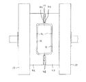
本発明の第1実施の形態に係る中空成形装置について、図1〜図7を参照して説明する。中空成形装置は、図1,図2に示すように押出装置のダイ・コア2を有し、ダイ・コア2からは、熱可塑性合成樹脂材料を筒状に予備成形したパリソン1が押出し垂下される。この押出装置のダイ・コア2からのパリソン1は、カッター3(カッター部)によつて切断部1cにおいて直径方向に切断され、縦割り2分割の左パリソン1a及び右パリソン1bとされる。カッター3は、図1上ではダイ・コア2の下方に配置してあるが、ダイ・コア2の下端部内の溶融樹脂の流路の直径方向の2箇所に配置し、このダイ・コア2に組み込まれたカッター部によつて2分割の左・右パリソン1a,1bを生成することもできる。つまり、カッター3が無くても、ダイ・コア2自体が2分割の左・右パリソン1a,1bを生成するようにカッター機能部材が構成されていればよい。切断された後の左パリソン1a及び右パリソン1bは、切断部1c付近が弾性的に開いて、断面が略楕円形状の一部をなしている。パリソン1は、単層ないし多層を使用することができる。なお、左パリソン1a及び右パリソン1bは、2つの押出装置のダイ・コアから個別に垂下させることもできる。   A hollow molding apparatus according to a first embodiment of the present invention will be described with reference to FIGS. The hollow molding apparatus has a die core 2 of an extrusion apparatus as shown in FIGS. 1 and 2, from which a parison 1 in which a thermoplastic synthetic resin material is preformed in a cylindrical shape is extruded and drooped. The The parison 1 from the die core 2 of this extrusion apparatus is cut in the diametrical direction by a cutter 3 (cutter portion) at a cutting portion 1c to be divided into two vertically divided left parison 1a and right parison 1b. Although the cutter 3 is disposed below the die core 2 in FIG. 1, the cutter 3 is disposed at two locations in the diameter direction of the flow path of the molten resin in the lower end portion of the die core 2. The divided left and right parisons 1a and 1b can be generated by the incorporated cutter unit. That is, even if the cutter 3 is not provided, the cutter function member may be configured such that the die core 2 itself generates the left and right parisons 1a and 1b divided into two. The left parison 1a and the right parison 1b after being cut are elastically opened in the vicinity of the cut portion 1c, and the cross section is a part of a substantially elliptical shape. The parison 1 can use a single layer or multiple layers. In addition, the left parison 1a and the right parison 1b can be individually suspended from the die cores of the two extrusion apparatuses.

ダイ・コア2の下方には、対をなす左・右金型4a,4bと、型開き状態の左・右金型4a,4bの間に挿脱自在な内金型5とが配置される。各10は、それぞれ左・右金型4a,4bを取り付けるプラテンである。左・右金型4a,4bは、それぞれ型開閉装置11,12によつて型開き又は型閉じされ、型合わせ面4d同士が密着する型閉じ状態で、意図する中空成形品(例えば車両用のガソリンタンク)の外形形状に適合するキャビティ4cを画成する。この型開閉装置11,12は、複動式のシリンダ装置によつて構成され、それぞれ左右の液圧室11a,11b,12a,12bに作動液を給排させることにより、左・右金型4a,4bが開閉駆動される。なお、左・右金型4a,4b及び左・右パリソン1a,1bは、切断したパリソン1a,1bを金型4a,4bに付着させて開くように実質的に対応する左・右金型4a,4b及び左・右パリソン1a,1bを有すればよく、3分割以上であつてもよい。   Below the die core 2, a pair of left and right molds 4a and 4b and an inner mold 5 that can be inserted and removed between the left and right molds 4a and 4b in an open state are disposed. . Each 10 is a platen to which the left and right molds 4a and 4b are attached. The left and right molds 4a and 4b are opened or closed by the mold opening and closing devices 11 and 12, respectively, and the intended hollow molded product (for example, for vehicles) is in a mold closed state in which the mold matching surfaces 4d are in close contact with each other. A cavity 4c that conforms to the outer shape of the gasoline tank is defined. The mold opening / closing devices 11 and 12 are constituted by a double-acting cylinder device, and supply and discharge hydraulic fluid to the left and right hydraulic chambers 11a, 11b, 12a, and 12b, respectively, so that the left and right molds 4a. , 4b are driven to open and close. The left and right molds 4a and 4b and the left and right parisons 1a and 1b substantially correspond to the left and right molds 4a so that the cut parisons 1a and 1b are attached to the molds 4a and 4b and opened. , 4b and left / right parisons 1a, 1b.

一方の金型4aには、空気吹き込み機構8が付属されている。この空気吹き込み機構8は、針状をなし、パリソン1に突き刺した後に空気(気体)を供給することができる。   An air blowing mechanism 8 is attached to one mold 4a. The air blowing mechanism 8 has a needle shape and can supply air (gas) after piercing the parison 1.

また、内金型5は、内金型本体5aと、内金型本体5aの左右方向の中央部に形成される突出部5bとを有している。この内金型本体5aは、その外形面の略全体を接触部とし、左・右パリソン1a,1bの内面に接触させてパリソン1a,1bに中空成形品の内面全体形状を与え、ひいては左・右金型4a,4bの内面であるキャビティ4cとの間で中空成形品として適正な肉厚を与える機能を有する。すなわち、内金型5の接触部となる内金型本体5aの外形面の略全体が、中空成形品1fの内面形状に適合し、左・右金型4a,4bの第1の型閉じ状態でのキャビティ4cよりも中空成形品1fの肉厚に相当する分だけ小さい形状をなしている。厳密には、後記するスペーサ部5dが左・右金型4a,4bの型合わせ面4dに当接する状態で、内金型本体5aと左・右金型4a,4bのキャビティ4cとの間で中空成形品として適正な肉厚を与える。但し、内金型本体5aは、キャビティ4cよりも小さい形状をなし、その外形面の少なくとも一部の接触部を左・右パリソン1a,1bの内面の少なくとも一部に密着させてパリソン1a,1bの部分的な肉厚調整を図ればよい。   The inner mold 5 includes an inner mold main body 5a and a protruding portion 5b formed at the center in the left-right direction of the inner mold main body 5a. The inner mold body 5a has substantially the entire outer surface as a contact portion and is brought into contact with the inner surfaces of the left and right parisons 1a and 1b to give the parisons 1a and 1b the entire inner surface shape of the hollow molded product. It has a function of giving an appropriate thickness as a hollow molded product between the right mold 4a, 4b and the cavity 4c which is the inner surface of the right mold 4a, 4b. That is, substantially the entire outer surface of the inner mold body 5a that is the contact portion of the inner mold 5 is adapted to the inner surface shape of the hollow molded product 1f, and the first mold closed state of the left and right molds 4a and 4b. The shape is smaller than the cavity 4c in FIG. 4 by an amount corresponding to the thickness of the hollow molded product 1f. Strictly speaking, the spacer 5d described later is in contact with the die mating surfaces 4d of the left and right molds 4a and 4b, and between the inner mold body 5a and the cavity 4c of the left and right molds 4a and 4b. Appropriate thickness is provided as a hollow molded product. However, the inner mold body 5a has a shape smaller than the cavity 4c, and at least a part of the outer surface of the inner mold body 5a is brought into close contact with at least a part of the inner surfaces of the left and right parisons 1a and 1b. What is necessary is just to plan partial thickness adjustment.

内金型5の突出部5bは、内金型5の左右方向の中央部に、内金型5を小形化しながら左・右パリソン1a,1b同士の密着を防ぐ目的で形成され、一回目の型閉じ(第1の型閉じ)状態での左・右パリソン1a,1bの切断部1c及びその付近を突出部5bの両側面に接触させ、切断部1c及びその付近同士の密着を防止する機能を有する。このため、突出部5bは、左・右金型4a,4bの型合わせ面4dに沿つて内金型本体5aの縦方向及び横方向の全周に形成されていることが望ましいが、所定間隔にて複数形成させた場合であつても、軟化状態の左・右パリソン1a,1b同士の密着を防ぐことは可能である。また、突出部5bのパリソン1a,1bが接触する箇所には、低摩擦係数のテフロン(登録商標)加工が施され、パリソン1a,1bが突出部5bに左・右金型4a,4bに比して強固に付着することを抑制してある。なお、左・右パリソン1a,1bに押圧される内金型本体5aの接触部にも、同様のテフロン(登録商標)被覆を施し、左・右金型4a,4bのキャビティ4c面に比して強固に付着することを抑制することができる。要するに、第1の型閉じ後の型開き時に、パリソン1a,1bが左・右金型4a,4bに付着する手段を施せばよく、テフロン(登録商標)被覆に代えて、左・右金型4a,4bに各左・右パリソン1a,1bを真空吸引によつて吸着する手段を設けることもできる。   The projecting portion 5b of the inner mold 5 is formed at the center in the left-right direction of the inner mold 5 for the purpose of preventing the left and right parisons 1a and 1b from sticking to each other while reducing the size of the inner mold 5. A function of preventing the cut portion 1c and the vicinity thereof from contacting each other by bringing the cut portions 1c and the vicinity thereof of the left and right parisons 1a and 1b in the mold closed (first mold closed) state into contact with both side surfaces of the protruding portion 5b. Have For this reason, it is desirable that the protruding portion 5b is formed on the entire circumference in the vertical and horizontal directions of the inner mold body 5a along the mold matching surfaces 4d of the left and right molds 4a and 4b. Even when a plurality of the left and right parisons 1a and 1b are softened, it is possible to prevent the left and right parisons 1a and 1b from being in close contact with each other. Further, the Teflon (registered trademark) processing with a low coefficient of friction is applied to the projecting portion 5b where the parisons 1a and 1b come into contact, and the parisons 1a and 1b are compared with the left and right molds 4a and 4b. Therefore, it is suppressed that it adheres firmly. A similar Teflon (registered trademark) coating is also applied to the contact portion of the inner mold body 5a pressed by the left and right parisons 1a and 1b, compared with the cavity 4c surface of the left and right molds 4a and 4b. Can be prevented from sticking firmly. In short, when the mold is opened after the first mold is closed, the parisons 1a and 1b may be provided with means for adhering to the left and right molds 4a and 4b. Instead of the Teflon (registered trademark) coating, the left and right molds may be used. A means for adsorbing the left and right parisons 1a and 1b by vacuum suction can be provided on 4a and 4b.

また、突出部5bの左右両側面には、図3に示すスペーサ部5dが突出形成され、左・右金型4a,4bの第1の型閉じのときに喰い切り部4eよりも外側の型合わせ面4dに当接し、型合わせ面4dに形成した喰い切り部4eと突出部5bとの間に隙間を形成する。この喰い切り部4eと突出部5bとの間の隙間は、余分な溶融樹脂を左・右金型4a,4bの型合わせ面4d,4dと突出部5bとの間の空間に逃がすためのものである。喰い切り部4eは、内金型5が左・右金型4a,4bの間から退避した状態で、左・右金型4a,4b同士が密着する型閉じ(第2の型閉じ)のときに、パリソン1a,1bの密着する切断部1c付近を喰い切る機能を有する。なお、左・右金型4a,4bのキャビティ4cと内金型5の内金型本体5aとの間に余分な溶融樹脂を生じないときは、スペーサ部5dを省略し、喰い切り部4eを突出部5bに当接させることもできる。このときは、内金型5が左・右金型4a,4bの間のセンター位置にある状態での型閉じ(第1の型閉じ)のときに、喰い切り部4eが突出部5bに当接し、パリソン1a,1bの切断部1c付近を喰い切ることになる。   In addition, spacer portions 5d shown in FIG. 3 are formed on both the left and right side surfaces of the protruding portion 5b so as to be outside the cut-off portion 4e when the first molds of the left and right molds 4a and 4b are closed. A gap is formed between the biting portion 4e formed on the die mating surface 4d and the protruding portion 5b in contact with the mating surface 4d. The gap between the biting portion 4e and the protruding portion 5b is for allowing excess molten resin to escape to the space between the mold fitting surfaces 4d and 4d of the left and right molds 4a and 4b and the protruding portion 5b. It is. When the inner die 5 is retracted from between the left and right dies 4a and 4b, the biting portion 4e is closed when the left and right dies 4a and 4b are in close contact with each other (second die closing). In addition, it has a function of cutting out the vicinity of the cutting portion 1c where the parisons 1a and 1b are in close contact with each other. When no excess molten resin is generated between the cavity 4c of the left and right molds 4a and 4b and the inner mold body 5a of the inner mold 5, the spacer portion 5d is omitted and the biting portion 4e is removed. It can also be brought into contact with the protruding portion 5b. At this time, when closing the mold (first mold closing) with the inner mold 5 in the center position between the left and right molds 4a and 4b, the biting portion 4e contacts the protruding portion 5b. In contact therewith, the vicinity of the cut portion 1c of the parisons 1a and 1b is bitten.

この内金型5は、図2に示すように内金型駆動装置である複動式のシリンダ装置7を備え、液圧室7a,7bに作動液を適宜に給排させることによつてピストン及びピストンロッド7cを介して駆動され、図2に矢印で示す水平方向(横方向(前後方向))に挿脱自在である。ピストンロッド7cの先端は、突出部5bに結合している。内金型5は、シリンダ装置7によつて駆動されて、型開き状態の左・右金型4a,4bの間のセンター位置に挿入配置され、また、左・右金型4a,4bの間から退避させた退避位置を採る。内金型5の自重は、ピストンロッド7cに付属する機構(図示せず)によつて支持されている。   As shown in FIG. 2, the inner die 5 includes a double-acting cylinder device 7 which is an inner die driving device, and a piston is obtained by appropriately supplying and discharging hydraulic fluid to and from the hydraulic chambers 7a and 7b. And it is driven via the piston rod 7c, and is detachable in the horizontal direction (lateral direction (front-rear direction)) indicated by an arrow in FIG. The tip of the piston rod 7c is coupled to the protruding portion 5b. The inner mold 5 is driven by the cylinder device 7 and is inserted and arranged at the center position between the left and right molds 4a and 4b in the mold open state, and between the left and right molds 4a and 4b. The retreat position retracted from the position is taken. The dead weight of the inner mold 5 is supported by a mechanism (not shown) attached to the piston rod 7c.

次に作用について説明する。
先ず、一対の左・右金型4a,4bを型開き(第1の型開き)し、シリンダ装置7を駆動して、型開き状態の左・右金型4a,4bの間のセンター位置に内金型5を挿入・位置させる。一方、押出装置のダイ・コア2からの筒状のパリソン1をカッター3に触れさせて中心軸線方向に切断し、縦割り2分割の左パリソン1a及び右パリソン1bとし、図3に示すように型開き状態の左金型4a及び右金型4bと内金型5との間の空間に2分割した該左右パリソン1a,1bを垂下させる。このとき、左パリソン1a及び右パリソン1bは、切断部1cが弾性的に開いて左・右金型4a,4bの対向する型合わせ面4dの間に位置している。
Next, the operation will be described.
First, the pair of left and right molds 4a and 4b are opened (first mold opening), and the cylinder device 7 is driven to the center position between the left and right molds 4a and 4b in the mold open state. Insert and position the inner mold 5. On the other hand, the cylindrical parison 1 from the die core 2 of the extrusion apparatus is brought into contact with the cutter 3 and cut in the direction of the central axis to obtain a left parison 1a and a right parison 1b which are divided into two vertically, as shown in FIG. The left and right parisons 1a and 1b divided into two spaces are suspended in the space between the left mold 4a and the right mold 4b and the inner mold 5 in the mold open state. At this time, the left parison 1a and the right parison 1b are located between the die matching surfaces 4d of the left and right molds 4a and 4b with the cut portion 1c elastically opened.

このように内金型5の周囲に左右パリソン1a,1bを可及的に非接触で被せた状態で、左・右金型4a,4bに第1の型閉じを与える。これにより、左パリソン1aは、図4に示すように切断部1c付近が左金型4aの型合わせ面4dと内金型5の突出部5bの左側面との間に挟まれながら、左金型4aのキャビティ4c面と内金型本体5aの接触部との間にも挟圧され、スペーサ部5dが左金型4aの型合わせ面4dに当接する。   In this manner, the left and right dies 4a and 4b are closed in the first mold closing state with the left and right parisons 1a and 1b covered as much as possible in a non-contact manner around the inner mold 5. Thereby, as shown in FIG. 4, the left parison 1a has a left metal mold that is sandwiched between the die-matching surface 4d of the left metal mold 4a and the left side surface of the protruding part 5b of the inner metal mold 5 as shown in FIG. A pressure is also applied between the cavity 4c surface of the mold 4a and the contact portion of the inner mold body 5a, and the spacer portion 5d comes into contact with the mold matching surface 4d of the left mold 4a.

同様に、右パリソン1bは、図4に示すように切断部1c付近が右金型4bの型合わせ面4dと内金型5の突出部5bの右側面との間に挟まれながら、右金型4bのキャビティ4c面と内金型本体5aの接触部との間にも挟圧され、スペーサ部5dが右金型4bの型合わせ面4dに当接する。   Similarly, as shown in FIG. 4, the right parison 1b has a right metal mold that is sandwiched between the die mating surface 4d of the right mold 4b and the right side surface of the protrusion 5b of the inner mold 5 near the cutting portion 1c. A pressure is also applied between the cavity 4c surface of the mold 4b and the contact portion of the inner mold body 5a, and the spacer portion 5d comes into contact with the mold matching surface 4d of the right mold 4b.

従つて、左・右パリソン1a,1bの切断部1c付近同士を非接触として金型4a,4bの型合わせ面4d,4dの間に位置させた状態で、内金型5の内金型本体5aの外形面の接触部を左・右パリソン1a,1bの内面に押圧させてパリソン1a,1bの中央部全体に肉厚減少又は肉厚増加つまり肉厚調整が図られる。肉厚増加は、肉厚減少が図られた部分の隣接箇所で自由な方向に得られる。内金型本体5aの外形面の一部の接触部を左・右パリソン1a,1bの内面の一部に押圧させる場合には、該接触部が押圧される箇所のパリソン1a,1bの肉厚低減化が自由な方向に図られる。   Therefore, the inner mold body of the inner mold 5 is located in a state where the vicinity of the cut portions 1c of the left and right parisons 1a and 1b are not in contact with each other and are positioned between the mold matching surfaces 4d and 4d of the molds 4a and 4b. The contact portion of the outer surface of 5a is pressed against the inner surfaces of the left and right parisons 1a and 1b to reduce the thickness or increase the thickness, that is, adjust the thickness of the entire central portion of the parison 1a and 1b. The increase in thickness can be obtained in a free direction at a location adjacent to the portion where the thickness is reduced. When a part of the contact portion of the outer surface of the inner mold body 5a is pressed against a part of the inner surface of the left / right parison 1a, 1b, the thickness of the parison 1a, 1b where the contact portion is pressed Reduction can be achieved in a free direction.

このとき、該接触部が押圧させられる箇所のパリソン1a,1bに、加工を施すことも可能である。この加工としては、中空成形品1fがガソリンタンクの場合のバッフルプレート(揺動防止板)や内部部品の取付座等の形成がある。また、内金型本体5aに予め付着させたインサート部品をパリソン1a,1bに取り付けることも可能である。これにより、中空成形品1fの生産性の向上及び低コスト化を実現することができる。金型4a,4bのキャビティ4c面と内金型5の内金型本体5aの外形面との間の隙間を増減変化させることにより、中空成形品1fに均一厚さのみならず任意の厚さを与えることが可能である。   At this time, it is also possible to process the parisons 1a and 1b where the contact portions are pressed. This processing includes formation of a baffle plate (swing prevention plate), a mounting seat for internal parts, etc. when the hollow molded product 1f is a gasoline tank. Moreover, it is also possible to attach the insert components previously attached to the inner mold body 5a to the parisons 1a and 1b. Thereby, improvement in productivity and cost reduction of the hollow molded product 1f can be realized. By changing the gap between the cavity 4c surface of the molds 4a and 4b and the outer surface of the inner mold body 5a of the inner mold 5 to the hollow molded product 1f, not only a uniform thickness but also any arbitrary thickness It is possible to give

その後、図5に示すように左・右金型4a,4bに第1の型開きを与える。このとき、パリソン1a,1bが左・右金型4a,4bに付着する手段の作用により、左パリソン1aが左金型4aに付着し、右パリソン1bが右金型4bに付着して、左・右金型4a,4bが開かれる。次いで、内金型5を左・右金型4a,4bの間から退避位置に退避させた後に、左・右金型4a,4bに第2の型閉じを与える。   Thereafter, as shown in FIG. 5, the first mold opening is given to the left and right molds 4a and 4b. At this time, due to the action of the means that the parisons 1a and 1b adhere to the left and right molds 4a and 4b, the left parison 1a adheres to the left mold 4a, the right parison 1b adheres to the right mold 4b, and the left -The right molds 4a and 4b are opened. Next, after the inner mold 5 is retracted from the left and right molds 4a and 4b to the retracted position, the second mold closing is applied to the left and right molds 4a and 4b.

この第2の型閉じにより、図6に示すように左・右金型4a,4bの型合わせ面4d,4d、特に喰い切り部4eによつて左・右パリソン1a,1bの切断部1c付近の全周を挟み込み軟化状態にある2分割したパリソン1a,1bを一体に密着・溶着させると共に、喰い切り部4eは、内金型5が左・右金型4a,4bの間から退避しているので、左・右金型4a,4b同士で密着して、パリソン1a,1bの密着する切断部1c付近の余肉を喰い切る。なお、左・右パリソン1a,1bは、第1の型閉じ後であつて後記する第2の型開き前に、切断刃26によつて左・右金型4a,4bの上方であつてカッター3よりも下方において、切断する。   By closing the second mold, as shown in FIG. 6, the left and right molds 4a and 4b have their mating surfaces 4d and 4d, particularly the cutting part 4e and the vicinity of the cut part 1c of the left and right parisons 1a and 1b. The two divided parisons 1a and 1b are in close contact and welded together while the inner die 5 is retracted from between the left and right dies 4a and 4b. Therefore, the left and right molds 4a and 4b are brought into close contact with each other, and the excess meat near the cutting portion 1c where the parisons 1a and 1b are in close contact with each other. The left and right parisons 1a and 1b are cut by the cutting blade 26 above the left and right molds 4a and 4b after the first mold is closed and before the second mold opening described later. Cut below 3.

引き続き、必要に応じて空気吹き込み機構8を突き刺して一体をなすパリソン1a,1bの密封空間内に空気を吹き込んで、パリソン1a,1bを左・右金型4a,4bのキャビティ4c内で膨らませ、中空成形品1fにブロー成形する。パリソン1a,1bは、左・右金型4a,4bに接することで冷却されて固化するが、吹き込まれた空気によつても冷却される。空気吹き込み機構8による左・右パリソン1a,1b内への空気吹き込みは、第2の型閉じと同時又は直前から開始し、中空成形品1fにブロー成形する。   Subsequently, if necessary, air is blown into the sealed space of the parisons 1a and 1b that are pierced with the air blowing mechanism 8 to inflate the parisons 1a and 1b in the cavities 4c of the left and right molds 4a and 4b, Blow molding into a hollow molded product 1f. The parisons 1a and 1b are cooled and solidified by contacting the left and right molds 4a and 4b, but are also cooled by the blown air. Air blowing into the left and right parisons 1a and 1b by the air blowing mechanism 8 starts at the same time as or immediately before the second mold closing, and blow-molds into the hollow molded product 1f.

左・右パリソン1a,1bの冷却・固化後、図7に示すように左・右金型4a,4bを型開き(第2の型開き)することにより、外形に型内面形状が良好に与えられた中空成形品1fが得られる。喰い切り部4eによつて喰い切られた切断部1c付近の余肉1gは、バリとして取り除く。左・右金型4a,4bに第1の型閉じを与える際、左・右パリソン1a,1bの若干の冷却がなされるので、中空成形品1fがブロー成形された後の冷却・固化に要する時間は短縮される。   After the left and right parisons 1a and 1b are cooled and solidified, the left and right molds 4a and 4b are opened (second mold opening) as shown in FIG. A hollow molded product 1f is obtained. The excess 1 g in the vicinity of the cut portion 1c cut by the cut-off portion 4e is removed as burrs. When the first mold closing is applied to the left and right molds 4a and 4b, the left and right parisons 1a and 1b are slightly cooled. Therefore, cooling and solidification after the hollow molded product 1f is blow molded is required. Time is shortened.

左・右金型4a,4bの第1の型閉じから第2の型閉じまでを可及的速やかに行い、第2の型閉じによつて左・右パリソン1a,1bの切断部1c付近を迅速に挟圧することにより、第1の型閉じによつて切断部1c付近を過度に冷却させることなく、切断部1c付近を十分に高い温度の軟化状態のままとして、第2の型閉じによつてパリソン1a,1bを一体に溶着させることが可能である。勿論、左・右パリソン1a,1bの切断部1c付近の再溶融又は接着剤による溶着又は接着作業は不要である。   From the first mold closing to the second mold closing of the left and right molds 4a and 4b is performed as quickly as possible. By the second mold closing, the vicinity of the cutting portion 1c of the left and right parisons 1a and 1b By quickly clamping, the vicinity of the cutting portion 1c remains in a softened state at a sufficiently high temperature without excessively cooling the vicinity of the cutting portion 1c by the first mold closing. Thus, it is possible to weld the parisons 1a and 1b together. Of course, remelting or welding or bonding work with an adhesive in the vicinity of the cut portion 1c of the left and right parisons 1a and 1b is unnecessary.

中空成形品1fに適正な肉厚が与えられるので、喰い切り部4eによつて喰い切る余肉1gを少なくすることにより、中空成形品1fの成形に要する樹脂原料の使用量を減少させ、コスト低減及び省エネルギーを図ることが可能になる。特に、中空成形品1fのブロー比の大きな局所に適正肉厚を与え、他の大部分の箇所に適正な薄肉状態を与えることが可能であり、薄肉箇所への二次加工の容易化が得られるのみならず、中空成形品1fを軽量化させて、コスト低減及び輸送コスト低減等の省エネルギーを図ることができる。ガソリンタンクにあつては、車両の隅所に装備されるため、一般に複雑形状となるが、このような製品において、所望の肉厚を設定できることによる効果は大きい。   Since the appropriate thickness is given to the hollow molded product 1f, the amount of resin raw material required for molding the hollow molded product 1f can be reduced by reducing the excess 1g bited off by the biting portion 4e. Reduction and energy saving can be achieved. In particular, it is possible to give an appropriate thickness to a portion where the blow ratio of the hollow molded product 1f is large, and to give an appropriate thin state to the other most places, facilitating secondary processing to the thin places. In addition, the hollow molded product 1f can be reduced in weight to save energy such as cost reduction and transportation cost reduction. A gasoline tank is generally provided with a complicated shape because it is installed in a corner of a vehicle. However, in such a product, the effect of being able to set a desired wall thickness is great.

ところで、第1実施の形態にあつては押出装置のダイ・コア2及び型開閉装置11,12を固定し、内金型駆動装置である複動式のシリンダ装置7によつて内金型5を移動させたが、ダイ・コア2及び型開閉装置11,12と内金型5とを相対移動させればよく、内金型5を固定し、ダイ・コア2及び型開閉装置11,12を移動させても同様の作用が得られる。   By the way, in the first embodiment, the die core 2 and the mold opening / closing devices 11 and 12 of the extrusion device are fixed, and the inner die 5 is moved by the double-acting cylinder device 7 which is an inner die driving device. However, the die core 2 and the mold opening / closing devices 11 and 12 and the inner mold 5 may be moved relative to each other, the inner mold 5 is fixed, and the die core 2 and the mold opening / closing devices 11 and 12 are moved. The same effect can be obtained by moving the.

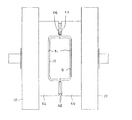
次に、本発明の第2実施の形態に係る中空成形装置について、図8〜図16を参照し、第1実施の形態と同一機能部分には同一符号を付して説明する。   Next, a hollow molding apparatus according to a second embodiment of the present invention will be described with reference to FIGS. 8 to 16 with the same reference numerals assigned to the same functional parts as those in the first embodiment.

第2実施の形態にあつては、第1実施の形態において押出装置のダイ・コア2及び型開閉装置11,12を固定し、内金型駆動装置である複動式のシリンダ装置7によつて内金型5を移動させるのに代えて、ダイ・コア2及び内金型5を固定し、型開閉装置11,12及び金型4a,4bを移動させる。また、カッター3及び空気吹き込み機構8は、備えていない。空気吹き込み機構8を省略したため、内金型本体5aは、その外形面の全体が形成する接触部をパリソン1の内面の中央部に押圧させてパリソン1の要部の全体的な肉厚調整を行う。   In the second embodiment, the die core 2 of the extrusion device and the mold opening / closing devices 11 and 12 are fixed in the first embodiment, and the double-action cylinder device 7 which is an inner mold driving device is used. Instead of moving the inner mold 5, the die core 2 and the inner mold 5 are fixed, and the mold opening / closing devices 11 and 12 and the molds 4 a and 4 b are moved. Further, the cutter 3 and the air blowing mechanism 8 are not provided. Since the air blowing mechanism 8 is omitted, the inner mold body 5a presses the contact portion formed by the entire outer surface against the central portion of the inner surface of the parison 1 to adjust the overall thickness of the main portion of the parison 1. Do.

すなわち、内金型5は、押出装置のダイ・コア2の下方に中心軸線を合致させて位置させて、図10,図11に示されるL字状の支持部材20を介して突出部5bの下端部を基台21に固定してある。内金型5の突出部5bは、内金型本体5aの縦方向及び横方向(上下及び前後方向)の全周に形成されている。突出部5bの左右両側面のスペーサ部5dは、省略してある。   That is, the inner mold 5 is positioned below the die core 2 of the extrusion device so that the center axis line is aligned, and the protrusion 5b is inserted through the L-shaped support member 20 shown in FIGS. The lower end is fixed to the base 21. The protrusion 5b of the inner mold 5 is formed on the entire circumference of the inner mold body 5a in the vertical direction and the horizontal direction (vertical and longitudinal directions). The spacer portions 5d on the left and right side surfaces of the protruding portion 5b are omitted.

従つて、喰い切り部4eは、左・右金型4a,4bが内金型5を挟んで型閉じ(第1の型閉じ)するときに中空成形品の各半部を整形すると同時に、内金型5の周囲のパリソン1を喰い切る機能を有する。このため、左・右金型4a,4bのキャビティ4cと内金型5の内金型本体5aとの間に余分な溶融樹脂を可及的に生じないように設計してある。   Therefore, when the left and right molds 4a and 4b close the inner mold 5 with the inner mold 5 closed (first mold closing), the bite cutting part 4e simultaneously shapes each half of the hollow molded product, It has a function of cutting away the parison 1 around the mold 5. For this reason, it is designed so that excess molten resin is not generated as much as possible between the cavity 4c of the left and right molds 4a and 4b and the inner mold body 5a of the inner mold 5.

一方、対をなす左・右金型4a,4bを型開き又は型閉じさせる型開閉装置11,12は、コ字状の成形機架台22に対向させて固設してある。成形機架台22は、基台21に設けた一対のレール23上を車輪24を介して前後方向に移動自在である。実際には、モータ等の駆動装置(図示せず)によつて成形機架台22を前後方向(図11上で左右方向)に移動させ、内金型5が左・右金型4a,4bの間のセンターに進入・位置する状態(図10に示す状態)と、内金型5を左・右金型4a,4bの間のセンター位置から相対的に退避させた退避位置(図11に示す位置)を採らせる。なお、各プラテン10は、成形機架台22上に案内させることができる。   On the other hand, the mold opening and closing devices 11 and 12 for opening and closing the paired left and right molds 4a and 4b are fixedly provided facing the U-shaped molding machine stand 22. The molding machine base 22 is movable in the front-rear direction via wheels 24 on a pair of rails 23 provided on the base 21. Actually, the molding machine base 22 is moved in the front-rear direction (left-right direction in FIG. 11) by a drive device (not shown) such as a motor, and the inner mold 5 is moved to the left and right molds 4a, 4b. And a retreat position (in FIG. 11) in which the inner mold 5 is relatively retreated from the center position between the left and right molds 4a and 4b. The position shown). Each platen 10 can be guided on the molding machine base 22.

次に作用について説明する。
先ず、図8〜図10に示すように対をなす左・右金型4a,4bを型開き(第1の型開き)して成形機架台22を相対移動させ、左・右金型4a,4bの間に内金型5を進入させた状態にする。
Next, the operation will be described.
First, as shown in FIGS. 8 to 10, the paired left and right molds 4a and 4b are opened (first mold opening), and the molding machine base 22 is moved relative to each other to move the left and right molds 4a. , 4b, the inner mold 5 is made to enter.

一方、押出装置のダイ・コア2からの筒状のパリソン1を2分割することなく垂下させ、型開き状態の左金型4a及び右金型4bと内金型5との間の空間に供給する。このとき、パリソン1は、十分に型開きした左金型4a及び右金型4b並びに内金型5と可及的に非接触状態で、図12に示すようにダイ・コア2からの吐出形状をほぼ維持している。   On the other hand, the cylindrical parison 1 from the die core 2 of the extrusion device is suspended without being divided into two parts, and is supplied to the space between the left mold 4a and the right mold 4b in the mold open state and the inner mold 5 To do. At this time, the parison 1 is in a non-contact state with the left and right molds 4a and 4b and the inner mold 5 as much as possible, and the discharge shape from the die core 2 as shown in FIG. Is almost maintained.

パリソン1が内金型5の周囲に被さるように垂下し、左・右金型4a,4bの型合わせ面4dの下端付近にまで達したなら、左・右金型4a,4bに第1の型閉じを与える。これにより、パリソン1の左側は、図13左半部に示すように周縁部が左金型4aの型合わせ面4dと内金型5の突出部5bの左側面との間に挟まれながら、中央部が左金型4aのキャビティ4c面と内金型本体5aの接触部との間に挟圧される。   When the parison 1 hangs down so as to cover the inner mold 5 and reaches the vicinity of the lower end of the die-matching surface 4d of the left and right molds 4a and 4b, the left and right molds 4a and 4b receive the first Give mold closure. As a result, the left side of the parison 1 is sandwiched between the mold fitting surface 4d of the left mold 4a and the left side of the protrusion 5b of the inner mold 5 as shown in the left half of FIG. The central part is sandwiched between the cavity 4c surface of the left mold 4a and the contact part of the inner mold body 5a.

同時に、パリソン1の右側は、図13右半部に示すように周縁部が右金型4bの型合わせ面4dと内金型5の突出部5bの右側面との間に挟まれながら、中央部が右金型4bのキャビティ4c面と内金型本体5aの接触部との間に挟圧される。   At the same time, as shown in the right half of FIG. 13, the right side of the parison 1 is centered while the peripheral edge is sandwiched between the matching surface 4 d of the right mold 4 b and the right side of the protrusion 5 b of the inner mold 5. The portion is sandwiched between the cavity 4c surface of the right mold 4b and the contact portion of the inner mold body 5a.

このとき、パリソン1の周縁部が型合わせ面4dに形成した左・右金型4a,4bの喰い切り部4eによつて突出部5bに押し付けられ、それぞれ環状の切断部1c’において切断され、2分割の左パリソン1a及び右パリソン1bとされる。左・右金型4a,4bの喰い切り部4eと突出部5bとの間の隙間から若干の余分な溶融樹脂が逃げることは許容される。   At this time, the peripheral portion of the parison 1 is pressed against the protruding portion 5b by the biting portions 4e of the left and right molds 4a and 4b formed on the die matching surface 4d, and is cut at the annular cutting portion 1c ′, The left parison 1a and the right parison 1b are divided into two parts. It is allowed that some excess molten resin escapes from the gap between the biting portion 4e and the protruding portion 5b of the left and right molds 4a and 4b.

かくして、ダイ・コア2から吐出されるパリソン1は、内金型5の退避開始前までの間、つまり次に左・右金型4a,4bを開くまでの間に左パリソン1a及び右パリソン1bに切断される。左右の切断部1c’によつて切断されて突出部5bの外周に残る余肉1hは、後にバリとして取り除く。   Thus, the parison 1 discharged from the die core 2 is left parison 1a and right parison 1b before the inner mold 5 starts to retract, that is, until the left and right molds 4a and 4b are opened next. Disconnected. The excess 1h that is cut by the left and right cutting portions 1c 'and remains on the outer periphery of the protruding portion 5b is later removed as a burr.

従つて、左・右パリソン1a,1bの切断部1c’付近同士を非接触として金型4a,4bの型合わせ面4d,4dの間に位置させた状態で、内金型本体5aの外形面の接触部を左・右パリソン1a,1bの内面に押圧させて、キャビティ4cとの間でパリソン1a,1bの中央部全体に肉厚減少又は肉厚増加つまり肉厚調整が図られる。肉厚増加は、肉厚減少が図られた部分の隣接箇所で自由な方向に得られる。内金型本体5aの外形面の一部の接触部を左・右パリソン1a,1bの内面の一部に押圧させる場合には、該接触部が押圧される箇所のパリソン1a,1bの肉厚低減化が自由な方向に図られる。パリソン1a,1bの肉厚低減化が自由な方向に得られる点で、パリソンの押出し時にその肉厚を制御するパリソンコントローラのように、上下方向のみで肉厚変更を行うものとは異なり、周方向を含んで自由な方向に肉厚調整が得られる。   Accordingly, the outer surface of the inner mold main body 5a is located in a state in which the vicinity of the cut portions 1c 'of the left and right parisons 1a and 1b are not in contact with each other and are positioned between the mold matching surfaces 4d and 4d of the molds 4a and 4b. Are pressed against the inner surfaces of the left and right parisons 1a and 1b, and the thickness of the central portion of the parisons 1a and 1b is reduced or increased between the cavities 4c. The increase in thickness can be obtained in a free direction at a location adjacent to the portion where the thickness is reduced. When a part of the contact portion of the outer surface of the inner mold body 5a is pressed against a part of the inner surface of the left / right parison 1a, 1b, the thickness of the parison 1a, 1b where the contact portion is pressed Reduction can be achieved in a free direction. Unlike the parison controller that controls the thickness of the parison 1a, 1b in a free direction, unlike the parison controller that controls the thickness of the parison during extrusion, The thickness can be adjusted in any direction including the direction.

その後、図14に示すように左・右金型4a,4bに第1の型開きを与える。このとき、パリソン1a,1bが左・右金型4a,4bに付着する手段の作用により、左パリソン1aが左金型4aに付着し、右パリソン1bが右金型4bに付着して、左・右金型4a,4bが開かれる。次いで、左・右金型4a,4bを図11に示すように退避位置まで移動させ、内金型5を挟むセンター位置から相対的に退避させた後に、左・右金型4a,4bに第2の型閉じを与える。喰い切り部4eによつて喰い切られた切断部1c’付近の余肉1hは、ロボットハンド(図示せず)により内金型5の突出部5bから取り除き、必要に応じてリサイクルする。   Thereafter, as shown in FIG. 14, the first mold opening is given to the left and right molds 4a and 4b. At this time, due to the action of the means that the parisons 1a and 1b adhere to the left and right molds 4a and 4b, the left parison 1a adheres to the left mold 4a, the right parison 1b adheres to the right mold 4b, and the left -The right molds 4a and 4b are opened. Next, the left and right molds 4a and 4b are moved to the retracted position as shown in FIG. 11, and after being relatively retracted from the center position sandwiching the inner mold 5, the left and right molds 4a and 4b are moved to the second position. Give a mold closure of 2. The excess 1h in the vicinity of the cut portion 1c 'cut out by the cut-off portion 4e is removed from the protruding portion 5b of the inner mold 5 by a robot hand (not shown) and recycled as necessary.

この第2の型閉じにより、図15に示すように左・右金型4a,4bの型合わせ面4d,4d、特に喰い切り部4eによつて左・右パリソン1a,1bの切断部1c’及びその付近を挟み込んで、軟化状態にある2分割したパリソン1a,1bの周囲を一体に密着・溶着させる。喰い切り部4eは、内金型5が左・右金型4a,4bの間から退避しているので、左・右金型4a,4b同士で密着する。なお、パリソン1(左・右パリソン1a,1b)は、第1の型閉じ後であつて左・右金型4a,4bを内金型5を挟むセンター位置から退避位置に退避させる前に、切断刃26により、左・右金型4a,4bの上方において、切断する。パリソン1a,1bは、左・右金型4a,4bに接することで冷却されて固化する。   Due to the second mold closing, as shown in FIG. 15, the left and right molds 4a and 4b have the mating surfaces 4d and 4d, particularly the cut-off portion 1c ′ of the left and right parisons 1a and 1b by the biting portion 4e. In addition, the vicinity of the two divided parisons 1a and 1b in a softened state is tightly adhered and welded together by sandwiching the vicinity thereof. The biting portion 4e is in close contact with the left and right molds 4a and 4b because the inner mold 5 is retracted from between the left and right molds 4a and 4b. Note that the parison 1 (left / right parison 1a, 1b) is after the first mold is closed and before the left / right molds 4a, 4b are retracted from the center position sandwiching the inner mold 5 to the retracted position. The cutting blade 26 cuts the upper part of the left and right molds 4a and 4b. The parisons 1a and 1b are cooled and solidified by contacting the left and right molds 4a and 4b.

左・右パリソン1a,1bの冷却・固化後、図16に示すように左・右金型4a,4bを型開き(第2の型開き)することにより、外形に型内面形状が良好に与えられた中空成形品1fが得られる。   After the left and right parisons 1a and 1b are cooled and solidified, the left and right molds 4a and 4b are opened (second mold opening) as shown in FIG. A hollow molded product 1f is obtained.

左・右金型4a,4bの第1の型閉じから第2の型閉じまでを可及的速やかに行い、第2の型閉じによつて左・右パリソン1a,1bの切断部1c’付近を迅速に挟圧することにより、第1の型閉じによつて切断部1c’付近を過度に冷却させることなく、切断部1c’付近を十分に高い温度の軟化状態のままとして、第2の型閉じによつてパリソン1a,1bを一体に密着・溶着させることが可能である。勿論、左・右パリソン1a,1bの切断部1c’付近の再溶融又は接着剤による溶着又は接着作業は不要である。   From the first mold closing to the second mold closing of the left and right molds 4a and 4b as quickly as possible, and by the second mold closing, in the vicinity of the cutting portion 1c 'of the left and right parisons 1a and 1b By rapidly clamping the second mold, the vicinity of the cut portion 1c ′ remains in a softened state at a sufficiently high temperature without excessively cooling the vicinity of the cut portion 1c ′ by closing the first die. By closing, the parisons 1a and 1b can be adhered and welded together. Of course, remelting or welding or bonding work with an adhesive in the vicinity of the cut portion 1c 'of the left and right parisons 1a and 1b is unnecessary.

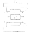
図17〜図21には、カッター部の他の構造例を示す。このカッター部である分割刃27は、内金型5の突出部5bに進退可能に設けてある。すなわち、駆動装置である複動式のシリンダ装置28を内金型5に前後対称に配設し、そのピストンロッドの先端にそれぞれ分割刃27を取り付けてある。   17 to 21 show other structural examples of the cutter unit. The split blade 27 which is this cutter part is provided in the protrusion part 5b of the inner metal mold | die 5 so that advance / retreat is possible. That is, a double-acting cylinder device 28 that is a drive device is disposed in the inner mold 5 in a longitudinally symmetrical manner, and a split blade 27 is attached to the tip of the piston rod.

この分割刃27は、左・右金型4a,4bの喰い切り部4eにより第1の型閉じのときに軟質状態のパリソン1を完全に切断することができない場合に装備される。分割刃27は、パリソン1の切断刃26による切断箇所近くからパリソン1の下端部までの上下方向の全幅にわたつて直径方向に切断して、左・右パリソン1a,1bを形成する機能を有する。すなわち、上記第2実施の形態では、図13に示す第1の型閉じのとき、パリソン1の周縁部が各型合わせ面4dに形成した喰い切り部4eによつて突出部5bに押し付けられ、それぞれ切断部1c’において切断され、2分割の左パリソン1a及び右パリソン1bとされ、両切断部1c’によつて切断されて突出部5bの外周に環状の余肉1hが残るものとしたが、軟質状態のパリソン1は完全に切断されず、図14に示すように左・右金型4a,4bに第1の型開きを与えるとき、パリソン1a,1bが余肉1hに引つ張られて変形する恐れがある。しかし、この構造例によれば、第1の型閉じのとき、分割刃27の機能によつてパリソン1が確実に左・右パリソン1a,1bに分割されるので、パリソン1a,1bが余肉1hに引つ張られて変形することが防止される。   The split blade 27 is provided when the parison 1 in the soft state cannot be completely cut when the first die is closed by the cut-off portions 4e of the left and right molds 4a and 4b. The split blade 27 has a function of cutting left and right parisons 1a, 1b by cutting in the diametrical direction over the entire vertical width from the vicinity of the cutting position of the parison 1 to the lower end of the parison 1. . That is, in the second embodiment, when the first mold is closed as shown in FIG. 13, the peripheral edge of the parison 1 is pressed against the protrusion 5b by the biting section 4e formed on each mold mating surface 4d. It is cut at the cutting portion 1c ′ to be divided into a left parison 1a and a right parison 1b, and is cut by both cutting portions 1c ′ to leave an annular surplus 1h on the outer periphery of the protruding portion 5b. The parison 1 in the soft state is not completely cut, and when the first mold opening is given to the left and right molds 4a and 4b as shown in FIG. 14, the parisons 1a and 1b are pulled by the surplus 1h. There is a risk of deformation. However, according to this structural example, when the first mold is closed, the parison 1 is surely divided into the left and right parisons 1a and 1b by the function of the dividing blade 27, so that the parisons 1a and 1b are left over. It is prevented from being deformed by being pulled to 1h.

内金型5の各シリンダ装置28の内室及び外室に接続する2対の配管29は、図8に仮想線で示すように突出部5b内を通して下方に配設され、支持部材20又は基台21に固設した制御装置30に接続させてある。しかして、制御装置30からの圧液を配管29を通して各シリンダ装置28の内室に供給することにより、一対の分割刃27が突出作動し、切断刃26による切断箇所より下方のパリソン1を中心軸線方向に切断し、縦割り2分割の左パリソン1a及び右パリソン1bとする。また、制御装置30からの圧液を配管29を通して各シリンダ装置28の室に供給し、室の作動液を排出させることにより、各分割刃27が没入作動する。
Two pairs of pipes 29 connected to the inner chamber and the outer chamber of each cylinder device 28 of the inner mold 5 are disposed below through the projecting portion 5b as indicated by phantom lines in FIG. It is connected to a control device 30 fixed to the table 21. Thus, by supplying the pressure fluid from the control device 30 to the inner chambers of the cylinder devices 28 through the pipes 29, the pair of split blades 27 project, and the parison 1 below the cutting position by the cutting blade 26 is centered. Cut in the axial direction to form a left parison 1a and a right parison 1b which are divided into two vertically. Also, it supplied to the outer chamber of each cylinder device 28 the liquid from the control device 30 through the pipe 29, by discharging the hydraulic fluid in the inner chamber, each of the divided blade 27 is retracted actuated.

この構造例によれば、図17に示すように第1の型閉じを与えた後に、図18に示すように各シリンダ装置28の内室に作動液を供給し、ピストンロッド及び分割刃27を突出させることにより、パリソン1の要部が中心軸線方向に切断され、縦割り2分割の左パリソン1a及び右パリソン1bとなる。かくして、ダイ・コア2から吐出されるパリソン1は、第1の型閉じを与えた後、内金型5の退避開始前までの間、つまり次に左・右金型4a,4bを開くまでの間に、突出部5bから突出する分割刃27によつて左パリソン1a及び右パリソン1bに切断される。第1の型閉じでは、上記第2実施の形態と同様に、左・右パリソン1a,1bの切断部1c’付近同士を非接触として金型4a,4bの型合わせ面4d,4dの間に位置させた状態で、内金型本体5aの外形面の接触部を左・右パリソン1a,1bの内面に押圧させて、パリソン1a,1bの中央部全体に肉厚減少又は肉厚増加つまり肉厚調整が自由な方向に図られる。   According to this structural example, after giving the first mold closing as shown in FIG. 17, the working fluid is supplied to the inner chambers of the cylinder devices 28 as shown in FIG. By making it protrude, the principal part of the parison 1 is cut | disconnected in the center axis direction, and becomes the left parison 1a and the right parison 1b of 2 division | segmentation vertically. Thus, the parison 1 discharged from the die core 2 is provided before the first mold closing and before the inner mold 5 starts to retract, that is, until the left and right molds 4a and 4b are opened next. In between, it is cut | disconnected by the division | segmentation blade 27 which protrudes from the protrusion part 5b into the left parison 1a and the right parison 1b. In the first mold closing, similarly to the second embodiment, the vicinity of the cut portions 1c ′ of the left and right parisons 1a and 1b is not contacted between the mold matching surfaces 4d and 4d of the molds 4a and 4b. In the state of being positioned, the contact portion of the outer surface of the inner mold body 5a is pressed against the inner surfaces of the left and right parisons 1a and 1b, so that the entire central portion of the parisons 1a and 1b decreases or increases in thickness. The thickness can be adjusted in any direction.

その後、図19に示すように左・右金型4a,4bに第1の型開きを与える。このとき、パリソン1a,1bが左・右金型4a,4bに付着する手段の作用により、左パリソン1aが左金型4aに付着し、右パリソン1bが右金型4bに付着して、左・右金型4a,4bが開かれる。突出部5bの外周に残る余肉1hは、左右に分割されているので、左・右金型4a,4bに付着したままで第1の型開きが行われる。   Then, as shown in FIG. 19, the first mold opening is given to the left and right molds 4a and 4b. At this time, due to the action of the means that the parisons 1a and 1b adhere to the left and right molds 4a and 4b, the left parison 1a adheres to the left mold 4a, the right parison 1b adheres to the right mold 4b, and the left -The right molds 4a and 4b are opened. Since the surplus 1h remaining on the outer periphery of the protruding portion 5b is divided into left and right, the first mold opening is performed while adhering to the left and right molds 4a and 4b.

次いで、左・右金型4a,4bを図11に示すと同様に、内金型5を挟むセンター位置から相対的に退避位置に移動させた後に、図20に示すように左・右金型4a,4bに第2の型閉じを与える。   Next, as shown in FIG. 11, the left and right molds 4a and 4b are moved relatively from the center position sandwiching the inner mold 5 to the retracted position, and then the left and right molds as shown in FIG. A second mold closing is given to 4a and 4b.

この第2の型閉じにより、図20に示すように左・右金型4a,4bの型合わせ面4d,4d、特に喰い切り部4eによつて左・右パリソン1a,1bの切断部1c’の付近を挟圧して、軟化状態にある2分割したパリソン1a,1bの周縁部を一体に溶着させると共に、切断部1c’の切断が促される。喰い切り部4eは、内金型5が左・右金型4a,4bの間から退避しているので、左・右金型4a,4b同士で良好に密着する。勿論、パリソン1(左・右パリソン1a,1b)は、第1の型閉じ後であつて左・右金型4a,4bを開く前に、切断刃26により、左・右金型4a,4bの上方において、切断する。   By this second mold closing, as shown in FIG. 20, the cut surfaces 1c ′ of the left and right parisons 1a and 1b are formed by the mating surfaces 4d and 4d of the left and right molds 4a and 4b, particularly by the biting portion 4e. , The peripheral portions of the two divided parisons 1a and 1b in a softened state are integrally welded, and the cutting of the cutting portion 1c ′ is promoted. Since the inner mold 5 is retracted from the left and right molds 4a and 4b, the left and right molds 4a and 4b are in close contact with each other. Of course, the parison 1 (left / right parison 1a, 1b) is cut by the cutting blade 26 before the left / right molds 4a, 4b after the first mold is closed and before the left / right molds 4a, 4b are opened. Cut above.

左・右パリソン1a,1bの冷却・固化後、図21に示すように左・右金型4a,4bを型開き(第2の型開き)することにより、外形に型内面形状(キャビティ4c形状)が良好に与えられた中空成形品1fが得られる。   After the left and right parisons 1a and 1b are cooled and solidified, the left and right molds 4a and 4b are opened (second mold opening) as shown in FIG. ) Is given a hollow molded product 1f.

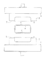
図22〜図27には、内金型5の他の構造例を示す。この内金型5にあつては、内金型本体5a’が、パリソン1の肉厚調整を図るための接触部を有していない。すなわち、内金型本体5a’は、キャビティ4cよりも小さい形状をなしているが、パリソン1の内面に押圧させて中空成形品の内面形状を与える接触部を積極的には有さず、左・右金型4a,4bが第1の型閉じし、突出部5bが左・右金型4a,4bの型合わせ面4dの喰い切り部4eに当接する状態で、キャビティ4cに対しパリソン1の肉厚に相当する分よりも更に小さい形状をなしている。また、左・右金型4a,4bのキャビティ4c面には、各左・右パリソン1a,1bを真空吸引によつて膨張させてキャビティ4c面に吸着する手段(図示せず)を備えている。   22 to 27 show other structural examples of the inner mold 5. For the inner mold 5, the inner mold body 5 a ′ does not have a contact portion for adjusting the wall thickness of the parison 1. That is, the inner mold body 5a ′ has a shape smaller than that of the cavity 4c, but does not actively have a contact portion that presses against the inner surface of the parison 1 to give the inner surface shape of the hollow molded product. The right molds 4a and 4b are closed with the first mold, and the projecting part 5b is in contact with the cut-out part 4e of the mold mating surface 4d of the left and right molds 4a and 4b. The shape is smaller than the thickness corresponding to the wall thickness. The left and right molds 4a and 4b are provided with means (not shown) on the surfaces of the cavities 4c to expand the left and right parisons 1a and 1b by vacuum suction and attract them to the surfaces of the cavities 4c. .

この内金型5を備える中空成形装置によれば、次の作用が得られる。先ず、図22に示すように一対の左・右金型4a,4bを型開き(第1の型開き)し、型開き状態の左・右金型4a,4bの間のセンター位置に内金型5を進入・位置させる。一方、押出装置のダイ・コア2からの筒状のパリソン1を切断することなく垂下させ、型開き状態の左金型4a及び右金型4bと内金型5との間の空間に位置させて内金型5に被せる。   According to the hollow molding apparatus provided with the inner mold 5, the following action is obtained. First, as shown in FIG. 22, the pair of left and right molds 4a and 4b is opened (first mold opening), and the inner mold is placed at the center position between the left and right molds 4a and 4b in the mold open state. The mold 5 is entered and positioned. On the other hand, the cylindrical parison 1 from the die core 2 of the extrusion apparatus is suspended without being cut, and is positioned in the space between the left mold 4a and the right mold 4b in the mold open state and the inner mold 5. And put on the inner mold 5.

このように内金型5の周囲にパリソン1を被せた状態で、左・右金型4a,4bに第1の型閉じを与える。これにより、パリソン1は、図23に示すように周縁部が左・右金型4a,4bの型合わせ面4dと内金型5の突出部5bの左・右側面との間に挟まれると同時に、パリソン1の周縁部が型合わせ面4dに形成した左・右金型4a,4bの喰い切り部4eによつて突出部5bに押し付けられ、それぞれ切断部1c’において環状に切断され、2分割の左パリソン1a及び右パリソン1bとされる。かくして、ダイ・コア2から吐出されるパリソン1は、内金型5の退避開始前(第1の型閉じ終了までの間)までの間、つまり次に左・右金型4a,4bを開くまでの間に左パリソン1a及び右パリソン1bに切断される。この第1の型閉じのとき、内金型本体5a’は、キャビティ4cとの間にパリソン1の肉厚に相当する分よりも大きな空間を形成しているので、パリソン1はキャビティ4c面と内金型本体5a’との間に挟圧されない。   In this manner, with the parison 1 covered around the inner mold 5, the first mold closing is applied to the left and right molds 4a and 4b. Accordingly, when the parison 1 is sandwiched between the mold matching surfaces 4d of the left and right molds 4a and 4b and the left and right sides of the protruding part 5b of the inner mold 5 as shown in FIG. At the same time, the peripheral portion of the parison 1 is pressed against the protruding portion 5b by the biting portion 4e of the left and right molds 4a and 4b formed on the die-matching surface 4d, and is cut into a ring shape at the cutting portion 1c ′. The left parison 1a and the right parison 1b are divided. Thus, the parison 1 discharged from the die core 2 opens the left and right molds 4a and 4b until the inner mold 5 is retracted (until the end of the first mold closing), that is, next. Until the left parison 1a and right parison 1b. When the first mold is closed, the inner mold body 5a ′ forms a space larger than the part corresponding to the thickness of the parison 1 between the inner mold body 5a ′ and the cavity 4c. It is not pinched between inner mold main body 5a '.

従つて、左・右パリソン1a,1bの切断部1c’付近同士を非接触として金型4a,4bの型合わせ面4d,4dの間に位置させた状態で、内金型本体5a’の外形面を左・右パリソン1a,1bの内面に積極的には押圧させず、パリソン1a,1bの中央部全体に肉厚調整を図ることなく、第1の型閉じが行われる。但し、パリソン1の切断部1c’付近は、内金型本体5a’の肩部を押圧し、突出部5bの外周に残る余肉1hに隣接する部分を成形すれば、成形品の切断部1c’同士の接合箇所を良好に平坦化させることができる。この場合、左・右金型4a,4bの内面(キャビティ4c面)と内金型5の外形面との間で一部の接触部をパリソン1に押圧させてパリソン1の肉厚調整が図られる。   Accordingly, the outer shape of the inner mold main body 5a ′ is located in a state where the vicinity of the cut portions 1c ′ of the left and right parisons 1a and 1b are not in contact with each other and are positioned between the mold matching surfaces 4d and 4d of the molds 4a and 4b. The first mold closing is performed without positively pressing the surface against the inner surfaces of the left and right parisons 1a and 1b and adjusting the thickness of the entire central portion of the parisons 1a and 1b. However, in the vicinity of the cut portion 1c ′ of the parison 1, if the shoulder portion of the inner mold main body 5a ′ is pressed and a portion adjacent to the excess 1h remaining on the outer periphery of the protruding portion 5b is formed, the cut portion 1c of the molded product is obtained. It is possible to satisfactorily flatten the joints between '. In this case, the wall thickness of the parison 1 can be adjusted by pressing a part of the contact portion against the parison 1 between the inner surfaces (cavity 4c surface) of the left and right molds 4a and 4b and the outer surface of the inner mold 5. It is done.

引き続き、左・右金型4a,4bをそれぞれ貫通させて設けた通孔から真空引きする。これにより、左・右パリソン1a,1bはそれぞれ伸長・膨んで、図24に示すように左・右金型4a,4bの内壁であるキャビティ4c面に密着する。つまり、キャビティ4c及び左・右パリソン1a,1bは、左・右パリソン1a,1bが若干膨張してキャビティ4c面に密着する大きさに形成してある。なお、真空引きに代えて、図8に示す配管29と同様に配設した気体配管を通じて内金型本体5a’から左右にエアー等の気体を吹き込んでも、図24に示すものと同様に膨んでキャビティ4c面に密着する。この真空引き又は気体吹き込みによる成形によれば、図8,図9に示す針状の空気吹き込み機構8をパリソン1に突き刺す必要がなく、中空成形品1fの傷つきを回避できると共に、空気吹き込み口を金型4a,4bの型合わせ面4d,4dに形成する必要もなく、自由な形状の中空成形品1fを得ることが可能になる。   Subsequently, the left and right molds 4a and 4b are evacuated from the through holes provided through the left and right molds 4a and 4b. As a result, the left and right parisons 1a and 1b expand and swell, and come into close contact with the cavity 4c surface, which is the inner wall of the left and right molds 4a and 4b, as shown in FIG. That is, the cavity 4c and the left and right parisons 1a and 1b are formed in such a size that the left and right parisons 1a and 1b expand slightly and come into close contact with the cavity 4c surface. Instead of evacuation, even if a gas such as air is blown from the inner mold body 5a ′ to the left and right through a gas pipe arranged in the same manner as the pipe 29 shown in FIG. 8, it expands in the same manner as shown in FIG. It closely adheres to the surface of the cavity 4c. According to this vacuuming or molding by gas blowing, it is not necessary to pierce the parison 1 with the needle-like air blowing mechanism 8 shown in FIGS. 8 and 9, and it is possible to avoid damage to the hollow molded product 1f and to provide an air blowing port. There is no need to form on the mold matching surfaces 4d and 4d of the molds 4a and 4b, and a hollow molded product 1f having a free shape can be obtained.

その後、図25に示すように左・右金型4a,4bに第1の型開きを与える。このとき、パリソン1a,1bが左・右金型4a,4bに付着する手段の作用により、左パリソン1aが左金型4aに付着し、右パリソン1bが右金型4bに付着して、左・右金型4a,4bが開かれる。次いで、左・右金型4a,4bを内金型5を挟むセンター位置から相対的に退避位置へと移動させた後に、左・右金型4a,4bに第2の型閉じを与える。喰い切り部4eによつて喰い切られた切断部1c’付近の環状の余肉1hは、ロボットハンド(図示せず)により内金型5の突出部5bから取り除く。   Thereafter, as shown in FIG. 25, the first mold opening is given to the left and right molds 4a and 4b. At this time, due to the action of the means that the parisons 1a and 1b adhere to the left and right molds 4a and 4b, the left parison 1a adheres to the left mold 4a, the right parison 1b adheres to the right mold 4b, and the left -The right molds 4a and 4b are opened. Next, after the left and right molds 4a and 4b are moved from the center position sandwiching the inner mold 5 to the retracted position, the second mold closing is applied to the left and right molds 4a and 4b. The annular excess 1h in the vicinity of the cutting portion 1c 'cut out by the biting portion 4e is removed from the protruding portion 5b of the inner mold 5 by a robot hand (not shown).

この第2の型閉じにより、図26に示すように左・右金型4a,4bの型合わせ面4d,4d、特に喰い切り部4eによつて左・右パリソン1a,1bの切断部1c’付近を環状に挟圧して、軟化状態にある2分割したパリソン1a,1bを一体に溶着させる。喰い切り部4eは、内金型5が左・右金型4a,4bの間から退避しているので、左・右金型4a,4b同士で密着する。なお、パリソン1(左・右パリソン1a,1b)は、第1の型閉じ後であつて左・右金型4a,4bを内金型5を挟むセンター位置から退避させる前に、切断刃26により、左・右金型4a,4bの上方において、切断する。パリソン1a,1bは、左・右金型4a,4bに接することで冷却されて固化する。   By the second mold closing, as shown in FIG. 26, the left and right molds 4a and 4b have the mating surfaces 4d and 4d, particularly the cut-off portion 1c ′ of the left and right parisons 1a and 1b by the biting portion 4e. The vicinity is annularly pressed and the two divided parisons 1a and 1b in a softened state are welded together. The biting portion 4e is in close contact with the left and right molds 4a and 4b because the inner mold 5 is retracted from between the left and right molds 4a and 4b. The parison 1 (left / right parison 1a, 1b) has a cutting blade 26 after the first mold is closed and before the left / right molds 4a, 4b are retracted from the center position sandwiching the inner mold 5. Thus, cutting is performed above the left and right molds 4a and 4b. The parisons 1a and 1b are cooled and solidified by contacting the left and right molds 4a and 4b.

左・右パリソン1a,1bの冷却・固化後、図27に示すように左・右金型4a,4bを型開き(第2の型開き)することにより、外形に金型4a,4bの型内面形状が良好に与えられた中空成形品1fが得られる。但し、パリソン1の肉厚調整は積極的には図られていない。   After the left and right parisons 1a and 1b are cooled and solidified, the left and right molds 4a and 4b are opened (second mold opening) as shown in FIG. A hollow molded product 1f having a favorable inner surface shape is obtained. However, the thickness adjustment of the parison 1 is not actively made.

本発明の第1実施の形態に係る中空成形装置を一部切開して示す正面図。1 is a front view illustrating a hollow molding apparatus according to a first embodiment of the present invention, partially cut away. 同じく図1のII−II線断面図。The II-II sectional view taken on the line of FIG. 同じく図1のA−A線断面にて示す作用説明図。The effect explanatory view similarly shown in the AA line section of FIG. 同じく図1のA−A線断面にて示す作用説明図。The effect explanatory view similarly shown in the AA line section of FIG. 同じく図1のA−A線断面にて示す作用説明図。The effect explanatory view similarly shown in the AA line section of FIG. 同じく図1のA−A線断面にて示す作用説明図。The effect explanatory view similarly shown in the AA line section of FIG. 同じく図1のA−A線断面にて示す作用説明図。The effect explanatory view similarly shown in the AA line section of FIG. 本発明の第2実施の形態に係る中空成形装置を一部切開して示す正面図。The front view which shows the hollow molding apparatus which concerns on 2nd Embodiment of this invention in part incision. 同じく図8のIX−IX線断面図。FIG. 9 is a cross-sectional view taken along the line IX-IX in FIG. 8. 同じくパリソンを省略して示す図8のX−X線断面図。XX sectional drawing of FIG. 8 which abbreviate | omits a parison similarly. 同じく図8のX−X線断面A−A線断面にて示す作用説明図。FIG. 9 is an explanatory view of the operation taken along line XX of FIG. 8 along line AA. 同じく図8のA−A線断面にて示す作用説明図。The effect explanatory view shown in the AA line section of Drawing 8 similarly. 同じく図8のA−A線断面にて示す作用説明図。The effect explanatory view shown in the AA line section of Drawing 8 similarly. 同じく図8のA−A線断面にて示す作用説明図。The effect explanatory view shown in the AA line section of Drawing 8 similarly. 同じく図8のA−A線断面にて示す作用説明図。The effect explanatory view shown in the AA line section of Drawing 8 similarly. 同じく図8のA−A線断面にて示す作用説明図。The effect explanatory view shown in the AA line section of Drawing 8 similarly. 他の構造例に係るカッター部を備えるときの図8のA−A線断面にて示す作用説明図。Action explanatory drawing shown in the AA line cross section of FIG. 8 when the cutter part which concerns on another structural example is provided. 同じく図8のA−A線断面にて示す作用説明図。The effect explanatory view shown in the AA line section of Drawing 8 similarly. 同じく図8のA−A線断面にて示す作用説明図。The effect explanatory view shown in the AA line section of Drawing 8 similarly. 同じく図8のA−A線断面にて示す作用説明図。The effect explanatory view shown in the AA line section of Drawing 8 similarly. 同じく図8のA−A線断面にて示す作用説明図。The effect explanatory view shown in the AA line section of Drawing 8 similarly. 他の構造例に係る内金型を備えるときの図12と同様の作用説明図。Action explanatory drawing similar to FIG. 12 when the inner metal mold | die which concerns on another structural example is provided. 同じく図13と同様の作用説明図。The same operation explanatory view as FIG. 同じく図13と同様の作用説明図。The same operation explanatory view as FIG. 同じく図14と同様の作用説明図。Similarly operation explanatory drawing similar to FIG. 同じく図15と同様の作用説明図。Similarly operation explanatory drawing similar to FIG. 同じく図16と同様の作用説明図。The same operation explanatory view as FIG. 従来の中空成形装置を示す断面図。Sectional drawing which shows the conventional hollow molding apparatus.

符号の説明Explanation of symbols

1:パリソン
1a:左パリソン
1b:右パリソン
1c,1c’:切断部
1f:中空成形品
1g:余肉
2:ダイ・コア
3:カッター(カッター部)
4a:左金型
4b:右金型
4c:キャビティ
4d:型合わせ面
4e:喰い切り部(カッター部)
5:内金型
5a,5a’:内金型本体
5b:突出部
5d:スペーサ部
7:シリンダ装置
11,12:型開閉装置
27:分割刃(カッター部)
1: Parison 1a: Left parison 1b: Right parison 1c, 1c ': Cutting part 1f: Hollow molded product 1g: Extra wall 2: Die core 3: Cutter (cutter part)
4a: Left mold 4b: Right mold 4c: Cavity 4d: Mold mating surface 4e: Cutting part (cutter part)
5: Inner mold 5a, 5a ': Inner mold body 5b: Protruding part 5d: Spacer part 7: Cylinder device 11, 12: Mold opening / closing device 27: Dividing blade (cutter part)

Claims (16)

正面視で、金型(4a,4b)より小さい形状の内金型(5)を型開き状態の金型(4a,4b)のセンター位置及び退避位置を相対的に採れるように設け、内金型(5)に被せるように熱可塑性合成樹脂材料を予備成形したパリソン(1)を押出し可能であると共に、内金型(5)に被せるように押出したパリソン(1)を内金型(5)の退避開始前までに左パリソン(1a)及び右パリソン(1b)に2分割し、左金型(4a)及び右金型(4b)からなる金型(4)に第1の型閉じを与え、パリソン(1)を内金型(5)と金型(4a,4b )との間に挟み、
切断したパリソン(1)の内の左パリソン(1a)を左金型(4a)に付着させ、右パリソン(1b)を右金型(4b)に付着させて左・右金型(4a,4b)を開き、内金型(5)を左・右金型(4a,4b)の間から相対的に退避させた後に、
左・右金型(4a,4b)に第2の型閉じを与え、左・右金型(4a,4b)によつて周囲を挟圧して軟化状態にある2分割したパリソン(1a,1b)を一体に溶着させ、
かつ、パリソン(1)を左・右金型(4a,4b)に接しさせることで冷却し、
中空成形品(1f)の形状を与えることを特徴とする中空成形方法。
An inner mold (5) having a smaller shape than the molds (4a, 4b) is provided in a front view so that the center position and the retracted position of the molds (4a, 4b) in the mold open state can be taken relatively. The parison (1) preformed with the thermoplastic synthetic resin material so as to cover the mold (5) can be extruded, and the parison (1) extruded so as to cover the inner mold (5) ) Before the start of evacuation, the left parison (1a) and the right parison (1b) are divided into two, and the mold (4) consisting of the left mold (4a) and the right mold (4b) is closed with the first mold closure. Giving the parison (1) between the inner mold (5) and the mold (4a, 4b),
The left parison (1a) of the cut parison (1) is attached to the left mold (4a), the right parison (1b) is attached to the right mold (4b), and the left and right molds (4a, 4b) are attached. ) And relatively retracting the inner mold (5) from between the left and right molds (4a, 4b),
The left and right molds (4a, 4b) are provided with a second mold closing, and the left and right molds (4a, 4b) are clamped around and softened into two divided parisons (1a, 1b) Are welded together,
In addition, the parison (1) is cooled by contacting the left and right molds (4a, 4b),
A hollow molding method characterized by giving a shape of a hollow molded article (1f).
正面視で、型開き状態の左・右金型(4a,4b)の間に、内金型(5)を相対移動させて配置させると共に押出装置のダイ・コア(2)からの熱可塑性合成樹脂材料を筒状に予備成形したパリソン(1)を型開き状態の左金型(4a)及び右金型(4b)と内金型(5)との間に垂下させ、内金型(5)の周囲に該パリソン(1)を配置させた状態で、
左・右金型(4a,4b)に第1の型閉じを与え、かつ、パリソン(1)を膨張させて左・右金型(4a,4b)の内面(4c)にパリソン(1)の少なくとも一部を密着させると共に、
内金型(5)の周囲に配置させる該パリソン(1)を内金型(5)の退避開始前までの間に左パリソン(1a)及び右パリソン(1b)に切断し、
切断したパリソン(1)の内の左パリソン(1a)を左金型(4a)に付着させ、右パリソン(1b)を右金型(4b)に付着させて左・右金型(4a,4b)を開き、内金型(5)を左・右金型(4a,4b)の間から相対的に退避させた後に、
左・右金型(4a,4b)に第2の型閉じを与え、左・右金型(4a,4b)によつて周囲を挟圧して軟化状態にある2分割したパリソン(1a,1b)を一体に溶着させ、かつ、パリソン(1)を左・右金型(4a,4b)に接しさせることで冷却し、中空成形品(1f)に成形することを特徴とする中空成形方法。
In front view , the inner mold (5) is relatively moved between the left and right molds (4a, 4b) in the mold open state, and the thermoplastic synthesis from the die core (2) of the extrusion device A parison (1) preliminarily molded with a resin material in a cylindrical shape is suspended between the left mold (4a) and the right mold (4b) in the mold open state and the inner mold (5), and the inner mold (5 ) With the parison (1) placed around
First mold closing is applied to the left and right molds (4a, 4b), and the parison (1) is expanded so that the inner surface (4c) of the left and right molds (4a, 4b) has the parison (1) At least partly adhere,
The parison (1) placed around the inner mold (5) is cut into a left parison (1a) and a right parison (1b) before the inner mold (5) starts to retract,
The left parison (1a) of the cut parison (1) is attached to the left mold (4a), the right parison (1b) is attached to the right mold (4b), and the left and right molds (4a, 4b) are attached. ), And relatively retracting the inner mold (5) from between the left and right molds (4a, 4b),
The left and right molds (4a, 4b) are provided with a second mold closing, and the left and right molds (4a, 4b) are clamped around and softened into two divided parisons (1a, 1b) And forming a hollow molded product (1f) by cooling by bringing the parison (1) into contact with the left and right molds (4a, 4b) .
前記第1の型閉じを与えるとき、内金型(5)の外形面の少なくとも一部の接触部をパリソン(1)に押圧させて、左・右金型(4a,4b)の内面(4c)との間で該パリソン(1)の肉厚調整を図ることを特徴とする請求項2の中空成形方法。 When the first mold closing is applied, at least a part of the outer surface of the inner mold (5) is pressed against the parison (1), and the inner surfaces (4c) of the left and right molds (4a, 4b) are pressed. The thickness of the parison (1) is adjusted between the first and second parisons (1). 前記パリソン(1)の切断が、第1の型閉じを与える前に、押出装置のダイ・コア(2)からのパリソン(1)を切断してなされることを特徴とする請求項2又は3の中空成形方法。 The cutting of the parison (1) is made by cutting the parison (1) from the die core (2) of the extruder before providing the first mold closure. Hollow molding method. 前記内金型(5)の左右方向の中央部に、左・右パリソン(1a,1b)同士の密着を防ぐ突出部(5b)が形成され、第1の型閉じの際、左・右パリソン(1a,1b)の切断部(1c)付近が突出部(5b)の両側面に接触することを特徴とする請求項2,3又は4の中空成形方法。 A protrusion (5b) is formed at the center of the inner mold (5) in the left-right direction to prevent the left and right parisons (1a, 1b) from sticking to each other, and the left and right parisons are closed when the first mold is closed. The hollow molding method according to claim 2, 3 or 4, wherein the vicinity of the cut portion (1c) of (1a, 1b) is in contact with both side surfaces of the protruding portion (5b). 前記内金型(5)の突出部(5b)の左右両側面にスペーサ部(5d)が突出形成され、左・右金型(4a,4b)の第1の型閉じのときにスペーサ部(5d)が左・右金型(4a,4b)の型合わせ面(4d)に当接し、左・右金型(4a,4b)の喰い切り部(4e,4e)と突出部(5b)との間に隙間を形成することを特徴とする請求項5の中空成形方法。 Spacer portions (5d) are formed to protrude on both the left and right side surfaces of the protruding portion (5b) of the inner mold (5). When the first mold of the left and right molds (4a, 4b) is closed, the spacer portion ( 5d) abuts against the mold-matching surface (4d) of the left and right molds (4a, 4b), and the biting parts (4e, 4e) and the protruding parts (5b) of the left / right molds (4a, 4b) 6. The hollow molding method according to claim 5, wherein a gap is formed between the two. 前記内金型(5)の左右方向の中央部に、左・右パリソン(1a,1b)同士の密着を防ぐ突出部(5b)が形成され、パリソン(1)の切断が、第1の型閉じを与える際に左・右金型(4a,4b)の喰い切り部(4e,4e)が突出部(5b)に押し付けられてなされることを特徴とする請求項2又は3の中空成形方法。 A protrusion (5b) that prevents the left and right parisons (1a, 1b) from sticking to each other is formed at the center in the left-right direction of the inner mold (5), and the cutting of the parison (1) is the first mold. The hollow molding method according to claim 2 or 3, wherein when the closing is given, the cut-off portions (4e, 4e) of the left and right molds (4a, 4b) are pressed against the protruding portions (5b). . 前記内金型(5)の左右方向の中央部に、左・右パリソン(1a,1b)同士の密着を防ぐ突出部(5b)が形成され、パリソン(1)の切断が、第1の型閉じを与えた後に突出部(5b)から突出する分割刃(27)によつてなされることを特徴とする請求項2又は3の中空成形方法。 A protrusion (5b) that prevents the left and right parisons (1a, 1b) from sticking to each other is formed at the center in the left-right direction of the inner mold (5), and the cutting of the parison (1) is the first mold. The hollow molding method according to claim 2 or 3, characterized in that it is performed by a split blade (27) protruding from the protruding portion (5b) after closing. 前記内金型(5)の接触部が、中空成形品(1f)のブロー比が大きくなる部分に隣接する部分にあり、中空成形品(1f)のブロー比が大きくなる部分の肉厚を増加させることを特徴とする請求項3の中空成形方法。 The contact portion of the inner mold (5) is adjacent to the portion where the blow ratio of the hollow molded product (1f) is increased, and the thickness of the portion where the blow ratio of the hollow molded product (1f) is increased is increased. The hollow molding method according to claim 3, wherein: 正面視で、内金型(5)に被せるように熱可塑性合成樹脂材料を予備成形したパリソン(1)を押出し、左・右金型(4a,4b)を閉じて該パリソン(1)を挟み込み、左・右金型(4a,4b)から該パリソン(1)を吸引し膨張させて該金型(4a,4b)内壁(4c)に密着させ、更に左・右金型(4a,4b)に2分割した該パリソン(1)をそれぞれ付着させたまま開き、内金型(5)を相対的に退避させ、再度左・右金型(4a,4b)を閉じて該パリソン(1)を密着成形し、かつ、パリソン(1)を左・右金型(4a,4b)に接しさせることで冷却し、最後に該金型(4a,4b)を開き該パリソン(1)からなる中空成形品(1f)を取り出す工程からなることを特徴とする中空成形方法。 When viewed from the front, the parison (1) preformed with a thermoplastic synthetic resin material so as to cover the inner mold (5) is extruded, the left and right molds (4a, 4b) are closed, and the parison (1) is sandwiched. The parison (1) is sucked and expanded from the left and right molds (4a, 4b) and brought into close contact with the inner wall (4c) of the mold (4a, 4b), and further the left and right molds (4a, 4b) The parison (1) divided into two parts is opened with each attached, the inner mold (5) is relatively retracted, the left and right molds (4a, 4b) are closed again, and the parison (1) is opened. Close molding and cooling by bringing the parison (1) into contact with the left and right molds (4a, 4b), and finally opening the mold (4a, 4b) to form a hollow mold comprising the parison (1) A hollow molding method comprising the step of taking out the product (1f). 正面視で、内金型(5)に被せるように熱可塑性合成樹脂材料を予備成形したパリソン(1)を押出し、左・右金型(4a,4b)を閉じて該パリソン(1)を挟み込み、内金型(5)から気体を吹込んで、該パリソン(1)を膨張させて該金型(4a,4b)内壁(4c)に密着させ、更に左・右金型(4a,4b)に2分割した該パリソン(1)をそれぞれ付着させたまま開き、内金型(5)を相対的に退避させ、再度左・右金型(4a,4b)を閉じて該パリソン(1)を密着成形し、かつ、パリソン(1)を左・右金型(4a,4b)に接しさせることで冷却し、最後に該金型(4a,4b)を開き該パリソン(1)からなる中空成形品(1f)を取り出す工程からなることを特徴とする中空成形方法。 When viewed from the front, the parison (1) preformed with a thermoplastic synthetic resin material so as to cover the inner mold (5) is extruded, the left and right molds (4a, 4b) are closed, and the parison (1) is sandwiched. Then, gas is blown from the inner mold (5), the parison (1) is expanded and brought into close contact with the inner wall (4c) of the mold (4a, 4b), and further to the left and right molds (4a, 4b). Open with the two parisons (1) attached, open the inner mold (5) relatively, close the left and right molds (4a, 4b) again, and attach the parison (1) closely The molded product is cooled by bringing the parison (1) into contact with the left and right molds (4a, 4b), and finally the mold (4a, 4b) is opened to form a hollow molded article made of the parison (1). (1f) A hollow molding method comprising the step of taking out. 前記パリソン(1)が、単層ないし多層をなしていることを特徴とする請求項1から1の中空成形方法。 The parison (1) is a hollow molding method of claims 1 1 1, characterized in that it forms a monolayer or multilayer. 正面視で、対をなす左・右金型(4a,4b)と、型開き状態の左・右金型(4a,4b)の間に相対的に挿脱自在な内金型(5)と、ダイ・コア(2)から吐出される熱可塑性合成樹脂材料を予備成形したパリソン(1)を内金型(5)の退避開始前までの間に左パリソン(1a)及び右パリソン(1b)に切断するカッター部(3,4e,27)とを有し、
型開き状態の左・右金型(4a,4b)と該左・右金型(4a,4b)の間に配置した内金型(5)との間に該パリソン(1)を垂下させ、
内金型(5)の周囲に該パリソン(1)を配置させた状態で、左・右金型(4a,4b)に第1の型閉じを与え、左・右金型(4a,4b)の内面(4c)にパリソン(1)の少なくとも一部を密着させた後、
左パリソン(1a)を左金型(4a)に付着させ、かつ、右パリソン(1b)を右金型(4b)に付着させて左・右金型(4a,4b)を開き、内金型(5)を左・右金型(4a,4b)の間から退避させた後に、左・右金型(4a,4b)に第2の型閉じを与え、
左・右金型(4a,4b)によつて周囲を挟圧して軟化状態の2分割した該パリソン(1a,1b)を一体に溶着させ、かつ、パリソン(1)を左・右金型(4a,4b)に接しさせることで冷却し、中空成形品(1f)に成形することを特徴とする中空成形装置。
An inner mold (5) that is relatively detachable between the paired left and right molds (4a, 4b) and the left and right molds (4a, 4b) in an open state in a front view; The left parison (1a) and the right parison (1b) between the parison (1) preliminarily molded from the thermoplastic synthetic resin material discharged from the die core (2) and before the inner mold (5) starts to retract. And a cutter part (3, 4e, 27) for cutting into
The parison (1) is suspended between the left and right molds (4a, 4b) in an open state and the inner mold (5) disposed between the left and right molds (4a, 4b).
With the parison (1) disposed around the inner mold (5), the left and right molds (4a, 4b) are closed with the first mold, and the left and right molds (4a, 4b) After adhering at least a part of the parison (1) to the inner surface (4c) of
The left parison (1a) is attached to the left mold (4a) and the right parison (1b) is attached to the right mold (4b) to open the left and right molds (4a, 4b), and the inner mold After retracting (5) from between the left and right molds (4a, 4b), a second mold closing is applied to the left and right molds (4a, 4b),
The left and right molds (4a, 4b) sandwich the softly divided parison (1a, 1b) by clamping the periphery and integrally weld the parison (1) to the left / right mold ( 4a, 4b) is cooled by being brought into contact therewith, and is formed into a hollow molded product (1f).
前記第1の型閉じを与えるとき、内金型(5)の少なくとも一部の接触部をパリソン(1)に押圧させて、左・右金型(4a,4b)の内面(4c)にパリソン(1)の少なくとも一部を密着させ、該パリソン(1)の肉厚調整を図ることを特徴とする請求項1の中空成形装置When providing the first mold closing, at least a part of the contact portion of the inner mold (5) is pressed against the parison (1), and the inner surface (4c) of the left and right molds (4a, 4b) is subjected to the parison. (1) at least a portion of the in close contact, claims 1 to 3 of a blow molding apparatus, characterized in that to achieve the thickness adjustment of the parison (1). 前記カッター部(3)が、ダイ・コア(2)に形成されていることを特徴とする請求項1の中空成形装置。 It said cutter unit (3), according to claim 1 3 of a blow molding apparatus characterized by being formed in a die core (2). 前記パリソン(1)が、単層ないし多層をなしていることを特徴とする請求項1,1又は1の中空成形装置。 The parison (1) is, according to claim 1 3, characterized in that it forms a monolayer or multilayer, 1 4 or 1 5 blow molding apparatus.
JP2004292110A 2004-10-05 2004-10-05 Hollow molding method and apparatus Active JP4093582B2 (en)

Priority Applications (1)

Application Number Priority Date Filing Date Title
JP2004292110A JP4093582B2 (en) 2004-10-05 2004-10-05 Hollow molding method and apparatus

Applications Claiming Priority (1)

Application Number Priority Date Filing Date Title
JP2004292110A JP4093582B2 (en) 2004-10-05 2004-10-05 Hollow molding method and apparatus

Publications (2)

Publication Number Publication Date
JP2006103116A JP2006103116A (en) 2006-04-20
JP4093582B2 true JP4093582B2 (en) 2008-06-04

Family

ID=36373361

Family Applications (1)

Application Number Title Priority Date Filing Date
JP2004292110A Active JP4093582B2 (en) 2004-10-05 2004-10-05 Hollow molding method and apparatus

Country Status (1)

Country Link
JP (1) JP4093582B2 (en)

Cited By (2)

* Cited by examiner, † Cited by third party
Publication number Priority date Publication date Assignee Title
KR101772056B1 (en) 2012-02-02 2017-09-12 카우텍스 마쉬넨바우 게엠베하 Method for producing a plastic article, and part of a blow-mould
US9950616B2 (en) 2010-12-03 2018-04-24 Jeffrey Yager Deployable fuel tank baffle and fuel tank system

Families Citing this family (11)

* Cited by examiner, † Cited by third party
Publication number Priority date Publication date Assignee Title
DE102008030318A1 (en) 2008-06-30 2009-12-31 Ti Automotive Technology Center Gmbh Process for producing a plastic container
EP2141000B1 (en) * 2008-06-30 2014-02-26 TI Automotive Technology Center GmbH Method of manufacturing an article and apparatus therefore
BR122020003472B1 (en) * 2009-06-25 2021-04-20 Ti Automotive Technology Center Gmbh method of making a plastic product comprising extruding a parison
US8377368B2 (en) 2009-12-11 2013-02-19 Ti Automotive Technology Center Gmbh Component mounting arrangement
US8721956B2 (en) 2010-03-03 2014-05-13 Ti Automotive Technology Center Gmbh Method of forming a fluid receptacle
DE102010026716B4 (en) * 2010-07-09 2013-01-24 Kautex Textron Gmbh & Co. Kg Blow mold and process for producing extrusion blow molded plastic articles
JP5809835B2 (en) * 2011-04-14 2015-11-11 ニチアス株式会社 Cutting device
DE102013203085A1 (en) 2013-02-25 2014-08-28 Ti Automotive Technology Center Gmbh blow molding
JP5740027B2 (en) * 2014-04-01 2015-06-24 八千代工業株式会社 Hollow molding product manufacturing apparatus and manufacturing method
US10265904B2 (en) 2014-12-05 2019-04-23 Yachiyo Industry Co., Ltd. Device for producing hollow container
KR101816789B1 (en) * 2016-11-29 2018-01-15 (주)동희산업 Forming apparatus of plastic fuel tank for vehicle

Cited By (2)

* Cited by examiner, † Cited by third party
Publication number Priority date Publication date Assignee Title
US9950616B2 (en) 2010-12-03 2018-04-24 Jeffrey Yager Deployable fuel tank baffle and fuel tank system
KR101772056B1 (en) 2012-02-02 2017-09-12 카우텍스 마쉬넨바우 게엠베하 Method for producing a plastic article, and part of a blow-mould

Also Published As

Publication number Publication date
JP2006103116A (en) 2006-04-20

Similar Documents

Publication Publication Date Title
JP4093582B2 (en) Hollow molding method and apparatus
KR100292971B1 (en) Method and apparatus for forming and hydraulic perforating tubular frame members
CA2802079C (en) Method for producing a plastics article and blow mold for carrying out the method
JP2012531334A (en) Container manufacturing method
JP2009539642A (en) Method for manufacturing hollow body made of thermoplastic material by extrusion blow molding with continuous adjustment of extrusion nozzle gap
JP2011073422A (en) Molding method
US20180147771A1 (en) Apparatus for forming plastic fuel tank for vehicle
JP7198994B2 (en) Molded body manufacturing method
TW201136804A (en) Manufacturing method of hollow blow molding box and mold structure thereof
JP3082493B2 (en) Blow molding method
JP6657551B2 (en) Method for manufacturing resin molded body
JP3861072B2 (en) Manufacturing method of semi-finished product for piston
JP3315045B2 (en) Method for manufacturing molded article by simultaneous filling hollow molding machine and mold
JP5345906B2 (en) Method for molding single wall structure made of thermoplastic resin
JP6970530B2 (en) Molding machine, hollow molding machine equipped with it, and manufacturing method of hollow molded product
JP7194323B2 (en) Molded body manufacturing method
CN218535590U (en) Two-piece type clamping blow molding die
JP2019081371A (en) Apparatus for molding container
JP3644676B2 (en) How to cut unnecessary molded parts in hollow mold
WO2020153436A1 (en) Die lip opening/closing device and method for manufacturing molded body
CN112743624B (en) Auxiliary mechanism and method for forming hollow body edge clamping hole
JPH11309773A (en) Blow mold and molding method thereof
US9469064B2 (en) Side blowing molding apparatus and method
JP7303974B2 (en) Molded body manufacturing method
JP3202778B2 (en) Blow molding method for resin molded products

Legal Events

Date Code Title Description
A977 Report on retrieval

Free format text: JAPANESE INTERMEDIATE CODE: A971007

Effective date: 20071116

A131 Notification of reasons for refusal

Free format text: JAPANESE INTERMEDIATE CODE: A131

Effective date: 20071127

A521 Request for written amendment filed

Free format text: JAPANESE INTERMEDIATE CODE: A523

Effective date: 20080114

TRDD Decision of grant or rejection written
A01 Written decision to grant a patent or to grant a registration (utility model)

Free format text: JAPANESE INTERMEDIATE CODE: A01

Effective date: 20080219

RD03 Notification of appointment of power of attorney

Free format text: JAPANESE INTERMEDIATE CODE: A7423

Effective date: 20080303

A61 First payment of annual fees (during grant procedure)

Free format text: JAPANESE INTERMEDIATE CODE: A61

Effective date: 20080303

FPAY Renewal fee payment (event date is renewal date of database)

Free format text: PAYMENT UNTIL: 20110314

Year of fee payment: 3

R150 Certificate of patent or registration of utility model

Ref document number: 4093582

Country of ref document: JP

Free format text: JAPANESE INTERMEDIATE CODE: R150

Free format text: JAPANESE INTERMEDIATE CODE: R150

FPAY Renewal fee payment (event date is renewal date of database)

Free format text: PAYMENT UNTIL: 20110314

Year of fee payment: 3

FPAY Renewal fee payment (event date is renewal date of database)

Free format text: PAYMENT UNTIL: 20120314

Year of fee payment: 4

FPAY Renewal fee payment (event date is renewal date of database)

Free format text: PAYMENT UNTIL: 20130314

Year of fee payment: 5

FPAY Renewal fee payment (event date is renewal date of database)

Free format text: PAYMENT UNTIL: 20140314

Year of fee payment: 6

R250 Receipt of annual fees

Free format text: JAPANESE INTERMEDIATE CODE: R250

R250 Receipt of annual fees

Free format text: JAPANESE INTERMEDIATE CODE: R250

R250 Receipt of annual fees

Free format text: JAPANESE INTERMEDIATE CODE: R250

R250 Receipt of annual fees

Free format text: JAPANESE INTERMEDIATE CODE: R250

R250 Receipt of annual fees

Free format text: JAPANESE INTERMEDIATE CODE: R250

R250 Receipt of annual fees

Free format text: JAPANESE INTERMEDIATE CODE: R250