JP4092855B2 - Printer unit - Google Patents
Printer unit Download PDFInfo
- Publication number
- JP4092855B2 JP4092855B2 JP2000145333A JP2000145333A JP4092855B2 JP 4092855 B2 JP4092855 B2 JP 4092855B2 JP 2000145333 A JP2000145333 A JP 2000145333A JP 2000145333 A JP2000145333 A JP 2000145333A JP 4092855 B2 JP4092855 B2 JP 4092855B2
- Authority
- JP
- Japan
- Prior art keywords
- paper
- guide member
- guide
- printer unit
- engagement
- Prior art date
- Legal status (The legal status is an assumption and is not a legal conclusion. Google has not performed a legal analysis and makes no representation as to the accuracy of the status listed.)
- Expired - Fee Related
Links
Images


Description
【0001】
【発明の属する技術分野】
本発明は、記録紙に印字するプリンタと、プリンタから排出される印字済み記録紙を排出口へ導入するガイド手段を備えた、レシートやチケット等長尺状用紙の発行に用いられるプリンタユニットに関し、特に、印字が完了するまで印字済み記録紙を排出口より外部に排出しないように、プリンタとガイド部の間に印字済み記録紙を保管する空間を備えたプリンタユニットに関する。
【0002】
【従来の技術】
レシートやチケット等を印字し発行するプリンタユニットは、ロール紙等の長尺記録紙から所定の長さの印字を完了したのち、カッタ装置等で裁断して排出口より取り出せる構成になっている。このようなプリンタユニットにおいては、記録紙が長尺状であり、印字を完了する前に排出口から記録紙を取り出すことが可能であると、印字途中に人手によって引っ張られることによる印字不良や装置の破損を招くことが懸念される。また、排出口を塞がれるなどした場合、プリンタユニット内部での紙詰りも想像される。さらに、用途上、発行物には私的情報や金銭に関わる情報を印字することもあり、セキュリティの見地から、発行を意図した本人以外の手に渡ることを防ぐ方策も必要とされる。
【0003】
一方、記録紙の補充頻度を少なくし、種々雑多な印字長さのレシート・チケット等を発行可能にすべく、通常、ロール状の記録紙が使われることが多い。芯径近くから搬送された記録紙には強い巻き癖が残っており、プリンタユニットに搬送される経路途中の構成によって、記録紙は、正規の経路より外部に迷走したり、スムーズに走行せず、紙詰りを生じ易くなる。また、記録紙によっては、プリンタユニットにセットする際の巻き方向が左右あり、巻き方向の違いによって、紙詰りを生じる場合もある。従って、プリンタユニット内を搬送する際には、記録紙を所定の経路通りに搬送し排出するため、ガイド部材等での規制を必要とする。
【0004】
従来、このようなプリンタユニットでは、印字を完了するまで排出口から記録紙を取り出せないように、印字途中においてプリンタユニット内部に設けた保管用の空間内で記録紙を保管し、印字完了後、カッタ装置等で裁断して排出口に搬送する構成になっていた。印字済み記録紙を取り出せる状態において該記録紙を取り出さなかった場合、前述したセキュリティ対策として、一定時間経過後、印字済み記録紙をプリンタユニット内部に引き戻すようになっていた。
【0005】
【発明が解決しようとする課題】
このような目的・構成の装置としては、例えば、特開平9−142708号等がある。この装置では、可撓性を有するガイド片を用い、プリンタ本体より排出された直後の印字済み記録紙先端を排出口方向に導くと共に、その可撓性を利用して印字済み記録紙をループ化し、保管用空間に保管している。
【0006】
しかしながら、このような構成の場合、記録紙はその厚みによってガイド片に与える力が変化することと、記録紙の巻き方向による、いわゆる「巻き癖」があり、ガイド片の撓み変位量が変わるため、特徴であるはずの「印字済み記録紙先端を確実に排出口方向に導くガイド機能」と、「記録紙をループ化させて保管用空間に保管すること」とは相容れない。即ち、紙のコシは、紙幅が同じであれば記録紙の厚みによって増減するため、厚い記録紙のガイド性を向上させるためにはガイド片の強度を上げて撓み量を抑えねばならず、記録紙をループ化させるための充分な撓み量を確保できなくなる。ガイド片の強度を下げて撓み量を確保すれば、ガイド性を損ない、記録紙が紙経路外に入り込んでしまって紙詰りになってしまうという問題があった。記録紙毎にガイド片を作成し、記録紙に見合ったガイド片を使用すればよいが、汎用性に欠け、実用的ではない。また、前述したように、記録紙によってはプリンタユニットにセットする際の巻き方向が左右あり、巻き癖の方向も異なるため、ガイド片に作用する力の方向も異なり、ガイド片の設定に注意を要する。これらの問題を解決するため、ガイド部材を二重構成とし、撓み量の少ない部材を長くしてその先端をプリンタ本体の出口近傍に配置し、記録紙のループ化を確保し、それより遠い側に撓み量の少ない部材を配置して厚い用紙のガイド性を向上させているが、何れにしろ、撓みという不安定な要素に頼っているため、確実性に乏しい。
【0007】
そこで本発明では、記録紙の形態に因らず、▲1▼記録紙を正規の搬送経路にガイドすること▲2▼記録紙をループ化させてプリンタユニット内部に保管すること、とを確実に行えるプリンタユニットを提供することを目的とする。
【0008】
【課題を解決するための手段】
上記問題を解決するため、本発明のプリンタユニットは、搬送される用紙の厚み方向における紙経路の少なくとも一部を形成し、前記用紙に押圧されても変形しないガイド部材と、前記ガイド部材が、前記用紙の厚み方向に規制して前記紙経路を形成する位置と前記紙経路を形成する位置より前記厚み方向に広い前記紙経路を開放する位置との間で変位するように、前記ガイド部材を支持する支持機構と、前記ガイド部材を前記紙経路を形成する位置にロックするロック機構とを備え、前記用紙の搬送に伴い当該用紙の先端が所定位置に到達することによって前記ロック機構のロックが解除されることを特徴とする。
ここで、前記ガイド部材は、係合部を有し、前記ロック機構は、前記ガイド部材の係合部と係合する係合部を有するロック部材と、前記ガイド部材の係合部と前記ロック部材の係合部とが係合する位置と係合しない位置との間で、前記ガイド部材と前記ロック部材の少なくとも一方を移動させる移動機構と、を備えていることを特徴とする。
また、前記ロック部材は、前記ガイド部材に対向して配置され、前記ガイド部材とともに前記紙経路の少なくとも一部を形成し、前記ガイド部材は、前記紙経路に対して略垂直方向に延びる細長状の係合穴を備え、前記支持機構は、前記ガイド部材の前記係合穴に係合し、前記ガイド部材を回動可能に支持する支持軸を備え、前記移動機構は、前記係合穴と前記支持軸とを含むことを特徴とする。
また、本発明のプリンタユニットは、搬送される用紙の厚み方向における紙経路の少なくとも一部を形成し、前記用紙に押圧されても変形しないガイド部材であって、係合部と、前記紙経路に対して略垂直方向に延びる細長状の係合穴と、を備えるガイド部材と、前記ガイド部材が前記紙経路を形成する位置と前記紙経路を開放する位置との間で変位するように、前記ガイド部材の前記係合穴に係合し前記ガイド部材を回動可能に支持する支持軸と、前記ガイド部材に対向して配置され前記ガイド部材と共に前記紙経路の少なくとも一部を形成し、前記ガイド部材を前記用紙の厚み方向に規制して前記紙経路を形成する位置にロックするロック部材であって、前記ガイド部材の係合部と係合する係合部を備えたロック部材と、前記ガイド部材の係合部と前記ロック部材の係合部とが係合する位置と係合しない位置との間で、前記ガイド部材と前記ロック部材の少なくとも一方を移動させる移動機構であって、前記係合穴と前記支持軸とを含む移動機構と、を備えることを特徴とする。
【0009】
また、前記ガイド部材の係合部と前記ロック部材の係合部とが係合した状態において、前記ガイド部材と前記ロック部材とで構成される間隙のうちの最狭部は、前記用紙の厚さより狭く形成され、前記係合状態における各係合部の係合代は、前記用紙の厚さより小さいことを特徴とする。
また、前記ガイド部材及び前記ロック部材は、それぞれの係合部を、前記用紙の幅方向両側に備えることを特徴とする。
また、前記支持機構は、前記ガイド部材を、その上流側が前記紙経路を開くように回動自在に支承することを特徴とする。
また、前記用紙が連続紙であることを特徴とする。
【0010】
【発明の実施の形態】
以下に、本発明の実施形態を図面を参照して説明する。
【0011】
図1は、本発明に係る実施形態を示す概略図である。
【0012】
プリンタユニット6は、概略、ロール状の感熱紙5の供給部4と、プリンタ本体3と、搬送部2とで構成されている。供給部4は、感熱紙5を保持し、感熱紙5の安定走行を促す機能を備え、プリンタ本体3は、感熱紙5に印字を施した上で、ロール状からシート状に裁断する役目を担う。搬送部2は、感熱紙5の印字が終了するまでの間、感熱紙5をプリンタユニット6の外部に露出しないよう保管する機能と、印字完了後、感熱紙5を外部に搬送する機能を有する。また、搬送部2は、ガイドピン21を介して、ユニットベース20のガイド溝20aに案内され、プリンタ本体3を露出することが可能で、プリンタ本体3及び搬送部2でのメンテナンス性を向上させている。
【0013】
先ず、供給部4の構成を説明する。ロール状の感熱紙5は、ロール紙ホルダ40に回動可能に保持されている。ロール紙ガイドローラ41は、プリンタ本体3の前紙ガイド31及び32に感熱紙5を導入する際のガイドになると共に、プリンタ本体3での感熱紙5の安定走行を実現するための緩衝機構になっている。プリンタ本体3の手前には、ガイド板42がベース板43に固定されている。ガイド板42は、感熱紙5の紙幅+αの寸法に両端を曲げて形成されており、感熱紙5の幅方向の規制をするようになっている。
【0014】
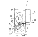
次に、図2を参照して、プリンタ本体3の構成を説明する。
【0015】
供給部4を経た感熱紙5をプリンタ本体3に導入するための前紙ガイド31及び後紙ガイド32は、ガイド板42同様、感熱紙5の紙幅+αの寸法に形成されており、感熱紙5の幅方向の規制をする。また、後紙ガイド32には、感熱紙5の走行で回動可能なレバー33を用いた透過型のフォトセンサ34が取り付けられている。レバー33には軸形状33aが形成されており、通常はバネで付勢されている。そして、レバー33が回動した時にその他端33bは、フォトセンサ34の光を遮り、信号を出力する。
【0016】
このフォトセンサ34は、プリンタ本体3に感熱紙5が挿入されたことと、感熱紙5がプリンタ本体3の内部に存在しないことの二項目を検知する役目を担う。サーマルヘッド30とプラテン36とはある一定の荷重を付加することにより圧接状態に保たれる。プラテン36の一方の軸端にはプラテンギヤ36aが固着され、モータ35からの駆動力を、減速ギヤ38と中間ギヤ39から伝達されて回転可能になっている。サーマルヘッド30とプラテン36の間隙に搬送された感熱紙5は、この回転駆動力によって、サーマルヘッド30との間で押圧されながら印字され、搬送方向Aに送られる。プリンタ本体3には、印字完了に同期して、感熱紙5を裁断するカッタユニット37が備えられている。
【0017】
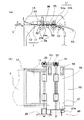
次に、図3を参照して、搬送部2の構成を説明する。
【0018】
図3(a)に示すように、上紙ガイド11と下紙ガイド12とが感熱紙5を挟むような位置に配置されてガイド部1を構成している。上紙ガイド11は樹脂製で、軸23に保持され、B及びC方向に回転可能になっている。上紙ガイド11先端11aは、プリンタ本体3より搬送されてきた感熱紙5を確実に経路上に導くことができるように、プリンタ本体3側に開いた形状になっており、下紙ガイド12に対しテーパを持った傾斜面11bに連続して形成されている。そして、軸23に対応する軸穴11gは、進行方向Aに対し鉛直方向の長穴となっており、その外側は長穴を肉厚分オフセットした形状に形成されている。また、図3(b)に示すように、感熱紙5の紙幅より外側においては、下紙ガイド12側に開いた形状の係合部11cを形成している。この係合部11cの先端部11dは、軸23の中心鉛直線上まで形成されている。一方、下紙ガイド12は、感熱紙5の裏面が接する搬送面12aとして水平な面形状を有し、その先端側は、軸23の中心鉛直線上まで形成され、係合面12bとしてある程度の肉厚をもって形成されている。
【0019】
上紙ガイド11の端部11eは、保持板13の面11aに当接してC方向への回転を規制されており、この状態で、上紙ガイド11の自重によって、上紙ガイド11は、軸23が軸穴11gの上側R面11fに接する位置まで下方に下がり、係合部11cは、下紙ガイド12の係合面12bに当接した状態になっている。この状態では、上紙ガイド11は、係合部11cと係合面12bとの当接状態によって、B方向への回転を規制されている。上紙ガイド11の上方側は、上紙ガイド11のB方向への回転半径外の空間14を確保されている。
【0020】
搬送方向A側に続いて、図4(a)に示すように、対峙する第一上ローラ24a及び第一下ローラ24bとで構成された第一搬送ローラ対24が配置されている。第一下ローラ24bは、軸22にゴム製のローラが形成されており、軸22の一端には、図4(b)に示すように、ギヤ25が固着され、他端にはプーリ26がそれぞれ固着されている。ギヤ25は中間ギヤ28と噛合しており、中間ギヤ28は、搬送モータ27のギヤ27aと噛合している。第一上ローラ24aは、軸23に樹脂製の部材が回動可能に保持された物であり、搬送部2の閉状態において、第一下ローラ24bと一定の押圧力を受けて密着するようになっている。そして、感熱紙5の搬送範囲内に透過型の第一フォトセンサ50が設置されている。対峙する第二上ローラ51a及び第二下ローラ51bとで構成された第二搬送ローラ対51が配置されており、第二搬送ローラ対51は、第一搬送ローラ対24同様の構成になっている。第一下ローラ24bのプーリ26と第二下ローラ51bのプーリ52とは、シンクロベルト53で同期して同じ方向に回転するようになっている。第二搬送ローラ対51と排出口60との間には、透過型の第二フォトセンサ54が設置されている。そして、第一搬送ローラ対24から排出口60に至る経路は、対峙する板金部材の紙搬送上ガイド55及び紙搬送下ガイド56で構成され、途中、感熱紙5の搬送範囲内に、第一フォトセンサ50及び第二フォトセンサ54の検出窓が2ヶ所設けてある。
【0021】
次に、本実施形態の動作を説明する。なお、動作の具体的な制御や駆動信号等の詳細については、本発明と直接な関わりがないため省略し、以下では時系列的に動作を説明する。
【0022】
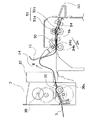
図5は、本実施形態のプリンタユニット6の動作を示す概略図である。
【0023】
まず、図1に示すように、供給部4のロール紙ホルダ40に感熱紙5をセットし、先端を引き出してロール紙ガイドローラ41に絡ませる。感熱紙5は、発色剤を塗布された片面(以下、印字面5aと称す。)のみに印字が可能であり、印字面5aはロール状態の表面側と裏面側の両タイプ流通している。印字面=表面の場合、図1に示す、アの向きになるように感熱紙5をセットする。印字面=裏面の場合は、イの向きになるようにセットする。そして、感熱紙5をガイド板42で幅方向の規制をし、前紙ガイド31及び後紙ガイド32とで形成された間隙に感熱紙5を挿入する。このとき、図5に示すように、感熱紙5は、後紙ガイド32に固着されたレバー33を回転させる。そして、レバー33の他端33aがフォトセンサ34の光軸34aを遮ることで、プリンタ本体3内部に感熱紙5が挿入されたことを検知し、モータ35が駆動して、感熱紙5をサーマルヘッド30とプラテン36とで挟み込み一定距離を搬送することで、感熱紙5のプリンタ本体3へのローディングを完了する。所定の印字信号を与えられると、サーマルヘッド30とプラテン36とで感熱紙5を搬送するのと平行して、サーマルヘッド30の発熱体が発熱し、感熱紙5に印字を行う。この状態では、カッタユニット37は動作していない。
【0024】
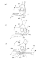
感熱紙先端5bは、上紙ガイド11と下紙ガイド12の間に搬送され、感熱紙先端5bは、先ず上紙ガイドの傾斜面11bに当接する。この時、図6(a)に示すように、感熱紙先端5bは、傾斜面11bをB方向に回転させる向きで押圧するが、係合部11cと係合面12bとの当接状態によってB方向への回転を規制されているため、感熱紙5を確実に搬送方向Aに導く。係合部11cと係合面12bとの当接状態は強固なため、感熱紙5の巻き癖の強弱や、コシの強さ・巻き方向に関わらず感熱紙5を確実に搬送方向Aに導くことが可能となる。このとき、上紙ガイド11の凸部11hと下紙ガイド12の搬送面12aは、ア部において密着している。そして、図6(b)に示すように、感熱紙5は、先端5bがア部まで搬送されると、上紙ガイド11の凸部11hと搬送面12aとの間に入り込むように進行する。そして、感熱紙5は、上紙ガイド11の軸穴11gに沿ってD方向へ移動するため、係合部11cと係合面12bとの当接状態が解除され、図6(C)に示すように、上紙ガイド11は、B方向への回転規制も解除された状態になる。
【0025】
そして、感熱紙5は、更に進行し、第一搬送ローラ対24によって先端5bを把持されて、搬送方向Aに搬送される。図7に示すように、先端5bが第一フォトセンサ50の検出位置に到達した時、搬送モータ27は停止され、第一搬送ローラ対24は、感熱紙5を把持した状態で停止する。この時、プラテンギヤ36aを駆動するモータ35は動作中であり、印字動作も継続中であるので、感熱紙5の搬送は停止していない。従って、先端5bの走行を止められた感熱紙5は、上紙ガイド11をB方向に押し回しながら、空間14に向かってループ状に進行する。
【0026】
そして、印字完了後、図8に示すように、カッタユニット37によって感熱紙5は裁断され、裁断完了後、搬送モータ27が起動して、第一搬送ローラ24a、24b及び第二搬送ローラ62a、62bによって、感熱紙5は排出口70からプリンタユニット6外部に搬送される。このとき、上紙ガイド11は、自重によってC方向へ自ら回転復帰し、係合部11cと係合面12bとの当接状態に戻ることで、待機状態になる。
【0027】
このような構成の場合、搬送されてきた感熱紙の先端が上紙ガイド先端の傾斜面に当接する際には、下紙ガイドと係合して上紙ガイドの回転を阻止しているので、感熱紙のコシや巻き癖の強弱、巻き方向に関わらず、その先端を確実に搬送経路内に導くことができるため、プリンタユニット内での感熱紙の紙詰りを防ぐことができる。
【0028】
また、感熱紙先端は、上紙ガイドの側面より底面に入り込むことで上紙ガイドを上方へ持ち上げて、係合部と係合面との当接状態を解除可能であって、第一搬送ローラ対が感熱紙を狭持して停止し感熱紙の保管状態になった際、搬送を続行されている感熱紙自らが上紙ガイドを回転させて、ループ状に保管用の空間に進行するため、感熱紙の保管を要する時のみループ状にして保管用空間に保管することができ、しかも感熱紙に折り目等傷を付けることがない。
【0029】
さらに、感熱紙自身の走行によって、ガイド性とループ性を要する場面において、ガイド部材の機能切り替えが自動的に可能となり、そのための駆動源を必要としない。
【0030】
しかも、ガイド部材の変形を利用していないため、安定した動作を実現できる。
【0031】
本実施形態では、上紙ガイドを移動させたが、記録紙のガイドとループ化の機能を持つ部材であれば、これに限定しない。
【0032】
また、回転移動としたが、記録紙のガイドを担う部材の少なくとも一つが移動可能であれば、回転移動に限定しない。
【0033】
また、上紙ガイドの自重で下紙ガイドとの係合状態を保持したが、より係合状態を確実とする場合、錘等を付加することも可能である。
【0034】
例として、プリンタ本体にサーマルプリンタを採用したが、これに限らず、記録紙等に印字・印刷を行うプリンタであれば、本発明は適用可能である。
【0035】
【発明の効果】
以上、説明したように、本発明のプリンタユニットにおいては、ガイド手段のうち少なくとも一つの部材に他のガイド部材やプリンタユニットの構成部材との係合手段を有し、係合手段のうち少なくとも一つの部材に、若干の移動が可能な移動手段を有することを特徴としている。従って、次の効果を有する。
a.ガイド手段は、係合している部材の移動手段によってその係合状態を解かれるため、ガイド性を要する時には係合状態を保持し、記録紙のループ化を要する時には移動手段によって係合状態を解除することができるので、ガイド性とループ化の両立が可能となる。しかも、ガイド手段の変形を利用していないので、記録紙の厚みや腰の強弱、巻き方向に因らず、ガイド性とループ化を確実に行うことができ、プリンタユニット内での紙詰りを防ぐことができる。
b.ガイド性とループ化をガイド部材のみで実現したため、構造が簡単で、動力源を使わないため、故障もなく安定した動作を保証できる。
c. 記録紙自身の走行によって、ガイド部材の係合状態を解除できるため、ガイド性とループ化それぞれを要する時に、何ら制御することなく両者の機能を切り替えることができる。
【図面の簡単な説明】
【図1】本発明に係る実施形態を示す概略図である。
【図2】本実施形態のプリンタユニットに内蔵されるプリンタ本体を示す概略図である。
【図3】(a)本実施形態のガイド部を示す側面概略図である。
(b)同、上面概略図である。
【図4】(a)本実施形態のガイド部を示す側面概略図である。
(b)同、上面概略図である。
【図5】本実施形態のプリンタユニットの感熱紙搬送動作を示す概略図である。
【図6】(a)本実施形態のガイド部に感熱紙が搬送された状態を示す概略図である。
(b)同ガイド部が感熱紙によって係合を解除された状態を示す概略図である。(c)同ガイド部の回転移動可能な状態を示す概略図である。
【図7】本実施形態のプリンタユニットの感熱紙のループ化動作を示す概略図である。
【図8】本実施形態のプリンタユニットの感熱紙の排出動作を示す概略図である。
【符号の説明】
1・・・・ガイド部
2・・・・搬送部
3・・・・プリンタ本体
4・・・・供給部
5・・・・感熱紙
6・・・・プリンタユニット
11・・・上紙ガイド
11a・・先端
11b・・傾斜面
11c・・係合部
11d・・先端部
11e・・端部
11f・・上側R面
11g・・軸穴
11h・・凸部
12・・・下紙ガイド
12a・・搬送面
12b・・係合面
13・・・保持板
14・・・空間
20・・・ユニットベース
20a・・ガイド溝
21・・・ガイドピン
22・・・軸
23・・・軸
24・・・第一搬送ローラ対
24a・・第一上ローラ
24b・・第一下ローラ
25・・・ギヤ
26・・・プーリ
27・・・搬送モータ
27a・・ギヤ
28・・・中間ギヤ
30・・・サーマルヘッド
31・・・前紙ガイド
32・・・後紙ガイド
33・・・レバー
33a・・軸形状
33b・・他端
34・・・フォトセンサ
35・・・モータ
36・・・プラテン
36a・・プラテンギヤ
37・・・カッタユニット
38・・・減速ギヤ
39・・・中間ギヤ
40・・・ロール紙ホルダ
41・・・ロール紙ガイドローラ
42・・・ガイド板
43・・・ベース板
50・・・第一フォトセンサ
51・・・第二搬送ローラ対
51a・・第二上ローラ
51b・・第二下ローラ
52・・・プーリ
53・・・シンクロベルト
54・・・第一フォトセンサ
55・・・紙搬送上ガイド
56・・・紙搬送下ガイド
60・・・排出口
A・・・・搬送方向
B・・・・ループ化回転方向
C・・・・ガイド待機方向
D・・・・係合解除方向
ア・・・・上紙ガイド・下紙ガイド当接位置[0001]
BACKGROUND OF THE INVENTION
The present invention relates to a printer unit for printing long sheets such as receipts and tickets, which includes a printer for printing on recording paper and guide means for introducing printed recording paper discharged from the printer to a discharge port. In particular, the present invention relates to a printer unit having a space for storing printed recording paper between a printer and a guide unit so that the printed recording paper is not discharged from a discharge port until printing is completed.
[0002]
[Prior art]
A printer unit that prints and issues receipts, tickets, and the like is configured to be able to be cut out by a cutter device or the like and taken out from a discharge port after printing a predetermined length from a long recording paper such as roll paper. In such a printer unit, if the recording paper is long and the recording paper can be taken out from the discharge port before the printing is completed, a printing failure or device caused by being pulled manually during printing. There is a concern that it may cause damage. In addition, when the discharge port is blocked, a paper jam inside the printer unit can be imagined. In addition, private information and money-related information may be printed on the issue for use, and measures to prevent it from being handed over to a person other than the person who intends to issue it are also required from a security standpoint.
[0003]
On the other hand, in order to reduce the replenishment frequency of the recording paper and to be able to issue receipt tickets and the like having various printing lengths, roll-shaped recording paper is usually used in many cases. Strong curl remains on the recording paper transported from near the core diameter, and the recording paper strays to the outside from the regular path or does not run smoothly due to the configuration in the middle of the path transported to the printer unit. , Paper jam easily occurs. Also, depending on the recording paper, the winding direction when set in the printer unit is left and right, and paper jams may occur depending on the difference in the winding direction. Therefore, when transporting the printer unit, the recording paper is transported and discharged along a predetermined route, and thus regulation by a guide member or the like is required.
[0004]
Conventionally, in such a printer unit, recording paper is stored in a storage space provided in the printer unit during printing so that the recording paper cannot be taken out from the discharge port until printing is completed. It was configured to be cut by a cutter device or the like and conveyed to a discharge port. When the recording paper is not taken out in a state where the printed recording paper can be taken out, as a security measure described above, the printed recording paper is pulled back into the printer unit after a predetermined time has elapsed.
[0005]
[Problems to be solved by the invention]
As an apparatus having such an object and configuration, for example, there is JP-A-9-142708. In this apparatus, a flexible guide piece is used to guide the front end of the printed recording paper immediately after being discharged from the printer main body in the direction of the discharge port, and the printed recording paper is looped using the flexibility. Stored in a storage space.
[0006]
However, in such a configuration, there is a change in the force applied to the guide piece depending on the thickness of the recording paper, and so-called “winding habit” due to the winding direction of the recording paper, and the amount of deflection displacement of the guide piece changes. , Which should be the feature, “the guide function that reliably guides the front end of the printed recording sheet in the direction of the discharge port” and “storing the recording sheet in a storage space in a loop” are incompatible. In other words, the stiffness of the paper increases or decreases depending on the thickness of the recording paper if the paper width is the same. Therefore, in order to improve the guideability of the thick recording paper, the strength of the guide piece must be increased to suppress the deflection amount. A sufficient amount of deflection for looping the paper cannot be secured. If the strength of the guide piece is lowered to ensure the amount of bending, there is a problem that the guide property is lost, and the recording paper enters the paper path and becomes jammed. A guide piece may be prepared for each recording sheet and a guide piece suitable for the recording sheet may be used, but it is not versatile and impractical. In addition, as described above, depending on the recording paper, the winding direction when setting it in the printer unit is left and right, and the direction of the curl is different, so the direction of the force acting on the guide piece is also different, so pay attention to the setting of the guide piece. Cost. In order to solve these problems, the guide member has a double structure, a member with a small amount of bending is lengthened and the tip thereof is arranged in the vicinity of the outlet of the printer main body, ensuring a loop of the recording paper, and a side farther than that However, the reliability of the thick paper is improved, but in any case, the reliability is poor because it relies on an unstable element such as bending.
[0007]
Therefore, in the present invention, regardless of the form of the recording paper, (1) guiding the recording paper to the regular transport path, and (2) looping the recording paper and storing it inside the printer unit are ensured. It is an object of the present invention to provide a printer unit that can be used.
[0008]
[Means for Solving the Problems]
In order to solve the above problem, the printer unit of the present invention forms at least a part of a paper path in the thickness direction of the conveyed paper, and the guide member that does not deform even when pressed by the paper, and the guide member includes: The guide member is arranged so as to be displaced between a position where the paper path is formed by regulating in the thickness direction of the paper and a position where the paper path wider in the thickness direction than the position where the paper path is formed. A support mechanism that supports the lock mechanism, and a lock mechanism that locks the guide member at a position where the paper path is formed. When the leading edge of the paper reaches a predetermined position as the paper is conveyed, the lock mechanism is locked. It is released.
Here, the guide member has an engaging portion, and the lock mechanism has a locking member having an engaging portion that engages with the engaging portion of the guide member, and the engaging portion of the guide member and the lock And a moving mechanism for moving at least one of the guide member and the lock member between a position where the engaging portion of the member is engaged and a position where the engaging portion is not engaged.
The lock member is disposed to face the guide member and forms at least a part of the paper path together with the guide member, and the guide member extends in a direction substantially perpendicular to the paper path. The support mechanism includes a support shaft that engages with the engagement hole of the guide member and rotatably supports the guide member, and the moving mechanism includes the engagement hole and the engagement hole. And the support shaft.
The printer unit of the present invention is a guide member that forms at least a part of a paper path in a thickness direction of a sheet to be conveyed and does not deform even when pressed by the paper, and includes an engaging portion and the paper path. An elongated engagement hole extending in a substantially vertical direction with respect to the guide member, and the guide member is displaced between a position where the paper path is formed and a position where the paper path is opened. A support shaft that engages with the engagement hole of the guide member and rotatably supports the guide member; and is disposed opposite the guide member to form at least a part of the paper path together with the guide member; A lock member that regulates the guide member in a thickness direction of the paper and locks it at a position where the paper path is formed, and includes a lock member that engages with an engagement portion of the guide member; The guide member A moving mechanism for moving at least one of the guide member and the lock member between a position where the engagement portion and the engagement portion of the lock member are engaged and a position where the engagement portion is not engaged. And a moving mechanism including the support shaft.
[0009]
In the state where the engaging portion of the guide member and the engaging portion of the lock member are engaged, the narrowest portion of the gap formed by the guide member and the lock member is the thickness of the sheet. The engagement margin of each engaging portion in the engaged state is smaller than the thickness of the sheet.
Further, the guide member and the lock member are provided with respective engaging portions on both sides in the width direction of the paper.
Further, the support mechanism is characterized in that the guide member is rotatably supported so that the upstream side opens the paper path.
Further, the paper is a continuous paper.
[0010]
DETAILED DESCRIPTION OF THE INVENTION
Embodiments of the present invention will be described below with reference to the drawings.
[0011]
FIG. 1 is a schematic view showing an embodiment according to the present invention.
[0012]
The printer unit 6 is roughly composed of a
[0013]
First, the configuration of the
[0014]
Next, the configuration of the printer
[0015]
Like the
[0016]
The
[0017]
Next, the configuration of the
[0018]
As shown in FIG. 3A, the
[0019]
The
[0020]
Subsequent to the conveyance direction A side, as shown in FIG. 4A, a first
[0021]
Next, the operation of this embodiment will be described. Note that detailed control of the operation, details of the drive signal, and the like are omitted because they are not directly related to the present invention, and the operation will be described in time series.
[0022]
FIG. 5 is a schematic diagram showing the operation of the printer unit 6 of this embodiment.
[0023]
First, as shown in FIG. 1, the
[0024]
The thermal
[0025]
Then, the
[0026]
After the printing is completed, as shown in FIG. 8, the
[0027]
In the case of such a configuration, when the leading edge of the thermal paper that has been conveyed contacts the inclined surface of the leading edge of the upper paper guide, it engages with the lower paper guide to prevent rotation of the upper paper guide. Regardless of the stiffness of the thermal paper, the strength and curl of the curl, and the winding direction, the leading edge can be reliably guided into the transport path, so that the thermal paper can be prevented from being jammed in the printer unit.
[0028]
The leading edge of the thermal paper enters the bottom surface from the side surface of the upper paper guide to lift the upper paper guide upward so that the contact state between the engaging portion and the engaging surface can be released. When the pair is stopped by holding the thermal paper and is in the thermal paper storage state, the thermal paper that is being transported itself rotates the upper paper guide and advances in a loop to the storage space Only when it is necessary to store the thermal paper, it can be looped and stored in the storage space, and the thermal paper is not damaged such as folds.
[0029]
Furthermore, the function of the guide member can be automatically switched in a scene where the guide property and the loop property are required by the running of the thermal paper itself, and a drive source for that purpose is not required.
[0030]
Moreover, since the deformation of the guide member is not used, stable operation can be realized.
[0031]
In this embodiment, the upper paper guide is moved, but the present invention is not limited to this as long as it is a member having a recording paper guide and a loop function.
[0032]
Further, although the rotational movement is described, the present invention is not limited to the rotational movement as long as at least one member that bears the recording paper guide is movable.
[0033]
Further, although the engagement state with the lower sheet guide is maintained by the weight of the upper sheet guide, a weight or the like can be added when the engagement state is further ensured.
[0034]
As an example, a thermal printer is adopted as the printer body. However, the present invention is not limited to this, and the present invention can be applied to any printer that performs printing / printing on recording paper or the like.
[0035]
【The invention's effect】
As described above, in the printer unit of the present invention, at least one member of the guide means has an engaging means with another guide member or a constituent member of the printer unit, and at least one of the engaging means. One member is characterized by having moving means capable of slight movement. Therefore, it has the following effects.
a. Since the engaging state of the guide means is released by the moving means of the engaged member, the engaged state is maintained when the guide property is required, and is engaged by the moving means when the recording paper is required to be looped. Since the state can be released, both guideability and looping can be achieved. In addition, since the deformation of the guide means is not used, guideability and looping can be performed reliably regardless of the thickness, stiffness, and winding direction of the recording paper, and paper jams in the printer unit can be prevented. Can be prevented.
b. Guidance and looping are realized with only the guide member, so the structure is simple and no power source is used, so that stable operation can be guaranteed without failure.
c. Since the engagement state of the guide member can be released by running the recording paper itself, the functions of both can be switched without any control when the guide property and the looping are required.
[Brief description of the drawings]
FIG. 1 is a schematic view showing an embodiment according to the present invention.
FIG. 2 is a schematic view showing a printer main body built in the printer unit of the embodiment.
FIG. 3A is a schematic side view showing a guide portion of the present embodiment.
(B) It is an upper surface schematic diagram.
FIG. 4A is a schematic side view showing a guide portion of the present embodiment.
(B) It is an upper surface schematic diagram.
FIG. 5 is a schematic diagram illustrating a thermal paper transport operation of the printer unit according to the embodiment.
FIG. 6A is a schematic diagram illustrating a state in which thermal paper is conveyed to the guide unit of the present embodiment.
(B) It is the schematic which shows the state by which the guide part was disengaged with the thermal paper. (C) It is the schematic which shows the state which the rotational movement of the guide part is possible.
FIG. 7 is a schematic diagram illustrating a thermal paper looping operation of the printer unit of the present embodiment.
FIG. 8 is a schematic diagram illustrating a thermal paper discharge operation of the printer unit according to the embodiment.
[Explanation of symbols]
DESCRIPTION OF
Claims (7)
前記ガイド部材が、前記用紙の厚み方向に規制して前記紙経路を形成する位置と前記紙経路を形成する位置より前記厚み方向に広い前記紙経路を開放する位置との間で変位するように、前記ガイド部材を支持する支持機構と、
前記ガイド部材を前記紙経路を形成する位置にロックするロック機構とを備え、
前記用紙の搬送に伴い当該用紙の先端が所定位置に到達することによって前記ロック機構のロックが解除されることを特徴とするプリンタユニット。A guide member that forms at least a part of the paper path in the thickness direction of the paper to be conveyed and does not deform even when pressed against the paper ;
The guide member is displaced between a position where the paper path is formed by regulating in the thickness direction of the paper and a position where the paper path wider in the thickness direction than the position where the paper path is formed. A support mechanism for supporting the guide member;
A lock mechanism for locking the guide member at a position where the paper path is formed;
The printer unit, wherein the lock mechanism is unlocked when the leading edge of the paper reaches a predetermined position as the paper is conveyed.
前記ロック機構は、
前記ガイド部材の係合部と係合する係合部を有するロック部材と、
前記ガイド部材の係合部と前記ロック部材の係合部とが係合する位置と係合しない位置との間で、前記ガイド部材と前記ロック部材の少なくとも一方を移動させる移動機構と、を備えていることを特徴とする請求項1に記載のプリンタユニット。The guide member has an engaging portion,
The locking mechanism is
A locking member having an engaging portion that engages with the engaging portion of the guide member;
A moving mechanism for moving at least one of the guide member and the lock member between a position where the engagement portion of the guide member and an engagement portion of the lock member are engaged and a position where the engagement portion is not engaged. The printer unit according to claim 1, wherein:
前記ガイド部材は、前記紙経路に対して略垂直方向に延びる細長状の係合穴を備え、
前記支持機構は、前記ガイド部材の前記係合穴に係合し、前記ガイド部材を回動可能に支持する支持軸を備え、
前記移動機構は、前記係合穴と前記支持軸とを含むことを特徴とする請求項2に記載のプリンタユニット。The lock member is disposed to face the guide member, and forms at least a part of the paper path together with the guide member;
The guide member includes an elongated engagement hole extending in a direction substantially perpendicular to the paper path,
The support mechanism includes a support shaft that engages with the engagement hole of the guide member and rotatably supports the guide member;
The printer unit according to claim 2, wherein the moving mechanism includes the engagement hole and the support shaft.
Priority Applications (9)
| Application Number | Priority Date | Filing Date | Title |
|---|---|---|---|
| JP2000145333A JP4092855B2 (en) | 2000-05-17 | 2000-05-17 | Printer unit |
| AT01109342T ATE512922T1 (en) | 2000-05-17 | 2001-04-12 | TRANSPORT UNIT FOR PRINT MEDIUM |
| ES01109342T ES2365034T3 (en) | 2000-05-17 | 2001-04-12 | TRANSPORTATION UNIT FOR PRINTING MEDIA. |
| EP01109342A EP1156001B1 (en) | 2000-05-17 | 2001-04-12 | Print-medium transport unit |
| US09/835,065 US6602008B2 (en) | 2000-05-17 | 2001-04-16 | Print-medium transport unit |
| KR10-2001-0020558A KR100520579B1 (en) | 2000-05-17 | 2001-04-17 | Print-medium transport unit, printer comprising the transport unit, control method used in the transport unit and storage medium comprising a computer program executed by the controller in the transport unit |
| CNB011212624A CN1182974C (en) | 2000-05-17 | 2001-04-17 | Means for conveying printing medium |
| CA002344131A CA2344131C (en) | 2000-05-17 | 2001-04-17 | Print-medium transport unit |
| HK02103146.5A HK1041467B (en) | 2000-05-17 | 2002-04-26 | Print-medium transport unit |
Applications Claiming Priority (1)
| Application Number | Priority Date | Filing Date | Title |
|---|---|---|---|
| JP2000145333A JP4092855B2 (en) | 2000-05-17 | 2000-05-17 | Printer unit |
Publications (3)
| Publication Number | Publication Date |
|---|---|
| JP2001322757A JP2001322757A (en) | 2001-11-20 |
| JP2001322757A5 JP2001322757A5 (en) | 2005-08-18 |
| JP4092855B2 true JP4092855B2 (en) | 2008-05-28 |
Family
ID=18651856
Family Applications (1)
| Application Number | Title | Priority Date | Filing Date |
|---|---|---|---|
| JP2000145333A Expired - Fee Related JP4092855B2 (en) | 2000-05-17 | 2000-05-17 | Printer unit |
Country Status (2)
| Country | Link |
|---|---|
| JP (1) | JP4092855B2 (en) |
| ES (1) | ES2365034T3 (en) |
Families Citing this family (2)
| Publication number | Priority date | Publication date | Assignee | Title |
|---|---|---|---|---|
| ATE512922T1 (en) * | 2000-05-17 | 2011-07-15 | Seiko Epson Corp | TRANSPORT UNIT FOR PRINT MEDIUM |
| JP2004189371A (en) * | 2002-12-09 | 2004-07-08 | Oki Electric Ind Co Ltd | Medium carrying passage |
-
2000
- 2000-05-17 JP JP2000145333A patent/JP4092855B2/en not_active Expired - Fee Related
-
2001
- 2001-04-12 ES ES01109342T patent/ES2365034T3/en not_active Expired - Lifetime
Also Published As
| Publication number | Publication date |
|---|---|
| ES2365034T3 (en) | 2011-09-20 |
| JP2001322757A (en) | 2001-11-20 |
Similar Documents
| Publication | Publication Date | Title |
|---|---|---|
| US6916132B2 (en) | Double-sided printing apparatus | |
| JPH10291707A (en) | Web roll and web roll containing cassette | |
| US7173643B2 (en) | Printing apparatus | |
| US8029203B2 (en) | Printer for recording images on a recording paper and feeding the paper backwards | |
| JP4092855B2 (en) | Printer unit | |
| JP2011110812A (en) | Recording device and recording medium supplying structure for the recording device | |
| JP4370730B2 (en) | Printing paper transport apparatus, control method thereof, and program | |
| JP3891370B2 (en) | Printer | |
| JP3535959B2 (en) | Roll paper mounting mechanism | |
| JP4858267B2 (en) | Printer device | |
| JP2012001331A (en) | Image recording device | |
| JPH1110970A (en) | Thermal printer | |
| JP3815125B2 (en) | Slack removal device for rolled web | |
| JP4274392B2 (en) | Roll sheet supply apparatus and image forming apparatus | |
| JP3520384B2 (en) | Printer | |
| JP4048899B2 (en) | Printer paper guide mechanism and printer having the same | |
| JP4905218B2 (en) | Printer device | |
| JP2021094763A (en) | Printer | |
| JP2001080148A (en) | Ink ribbon cassette | |
| JP2764562B2 (en) | Recording device | |
| JP2021054570A (en) | Printer | |
| JP2006281668A (en) | Identification printing device | |
| JPH1179471A (en) | Card carrying mechanism | |
| JPH1179497A (en) | Card issuing device | |
| JP2000327190A (en) | Image forming device |
Legal Events
| Date | Code | Title | Description |
|---|---|---|---|
| A521 | Written amendment |
Free format text: JAPANESE INTERMEDIATE CODE: A523 Effective date: 20050128 |
|
| A621 | Written request for application examination |
Free format text: JAPANESE INTERMEDIATE CODE: A621 Effective date: 20050128 |
|
| A977 | Report on retrieval |
Free format text: JAPANESE INTERMEDIATE CODE: A971007 Effective date: 20070314 |
|
| A131 | Notification of reasons for refusal |
Free format text: JAPANESE INTERMEDIATE CODE: A131 Effective date: 20070327 |
|
| A521 | Written amendment |
Free format text: JAPANESE INTERMEDIATE CODE: A523 Effective date: 20070515 |
|
| A131 | Notification of reasons for refusal |
Free format text: JAPANESE INTERMEDIATE CODE: A131 Effective date: 20070925 |
|
| A521 | Written amendment |
Free format text: JAPANESE INTERMEDIATE CODE: A523 Effective date: 20071120 |
|
| TRDD | Decision of grant or rejection written | ||
| A01 | Written decision to grant a patent or to grant a registration (utility model) |
Free format text: JAPANESE INTERMEDIATE CODE: A01 Effective date: 20080212 |
|
| A61 | First payment of annual fees (during grant procedure) |
Free format text: JAPANESE INTERMEDIATE CODE: A61 Effective date: 20080225 |
|
| FPAY | Renewal fee payment (event date is renewal date of database) |
Free format text: PAYMENT UNTIL: 20110314 Year of fee payment: 3 |
|
| R150 | Certificate of patent or registration of utility model |
Free format text: JAPANESE INTERMEDIATE CODE: R150 |
|
| FPAY | Renewal fee payment (event date is renewal date of database) |
Free format text: PAYMENT UNTIL: 20120314 Year of fee payment: 4 |
|
| FPAY | Renewal fee payment (event date is renewal date of database) |
Free format text: PAYMENT UNTIL: 20120314 Year of fee payment: 4 |
|
| FPAY | Renewal fee payment (event date is renewal date of database) |
Free format text: PAYMENT UNTIL: 20130314 Year of fee payment: 5 |
|
| FPAY | Renewal fee payment (event date is renewal date of database) |
Free format text: PAYMENT UNTIL: 20140314 Year of fee payment: 6 |
|
| S531 | Written request for registration of change of domicile |
Free format text: JAPANESE INTERMEDIATE CODE: R313531 |
|
| R350 | Written notification of registration of transfer |
Free format text: JAPANESE INTERMEDIATE CODE: R350 |
|
| LAPS | Cancellation because of no payment of annual fees |