JP4092425B2 - Gaming machine board box - Google Patents
Gaming machine board box Download PDFInfo
- Publication number
- JP4092425B2 JP4092425B2 JP2002069009A JP2002069009A JP4092425B2 JP 4092425 B2 JP4092425 B2 JP 4092425B2 JP 2002069009 A JP2002069009 A JP 2002069009A JP 2002069009 A JP2002069009 A JP 2002069009A JP 4092425 B2 JP4092425 B2 JP 4092425B2
- Authority
- JP
- Japan
- Prior art keywords
- opening
- cover
- cut
- cutting
- cover member
- Prior art date
- Legal status (The legal status is an assumption and is not a legal conclusion. Google has not performed a legal analysis and makes no representation as to the accuracy of the status listed.)
- Expired - Lifetime
Links
Images

Description
【0001】
【発明の属する技術分野】
本発明は、パチンコ機、アレンジボール機、雀球機、スロットルマシン等の遊技機の基板ボックスに関する。
【0002】
【従来の技術】
例えば、遊技ホール等に設置されているパチンコ機等の遊技機には、電子部品が実装された制御基板(回路基板とも呼ばれる)を収容した「基板ボックス」が設けられている。
この種の基板ボックスでは、その内部の電子部品、例えばROMが不正に交換されたり、そのROMに記憶された内容が不正に書き換えられたりする等の不正行為を防止するための封印手段が設けられている。
【0003】
次に、封印手段が設けられた基板ボックスの従来例を図面を参照して述べる。
図15は基板ボックスの封印手段を示す正面図、図16は図15のXVI−XVI線断面図、図17は図15のXVII−XVII線断面図である。
図16および図17に示すように、基板ボックス118は、セット部材120と、そのセット部材120に開閉可能に設けられたカバー部材130とを備えている。
セット部材120とカバー部材130によって形成される内部空間には、ROM、トランジスタ等の電子部品が実装された制御基板が収容されている。
【0004】
図16に示すように、セット部材120とカバー部材130との間には、そのセット部材120に対しカバー部材130を閉じた状態に封印するための封印手段140が設けられている。
封印手段140は、セット部材120側(セット側と略す)の連結部124とカバー部材130側(カバー側と略す)の連結部134とかしめ部材142と封印ねじ143とを備えている。
セット側の連結部124は、前記セット部材120に対しアーム状の開封部(セット側の開封部という)122を介して一体状に連設されている。
カバー側の連結部124は、前記カバー部材130に対しアーム状の開封部(カバー側の開封部という)132を介して一体状に連設されている(図15参照)。
セット側の連結部124とカバー側の連結部134とは、セット部材120にカバー部材130を閉じた状態において前後方向に延びる軸線L(図16参照)上に並んでいる。
【0005】
図16に示すように、前記かしめ部材142は、前記カバー側の連結部134内に挿入されて回り止めされた状態に配置されている。
かしめ部材142の先端部142aは、セット側の連結部124内に突出されている。
また、前記封印ねじ143は、一方向ねじ(ワンウエイねじとも呼ばれている)からなり、前記カバー部材130側の連結部134側より前記かしめ部材142にねじ込まれている。
封印ねじ143のねじ込みによって、かしめ部材142の先端部142aが押し広げられてセット側の連結部124にかしめつけられている。
これにより、セット部材120にカバー部材130が閉じた状態に固定すなわち封印されている。
【0006】
ところで、前記基板ボックス118内の検査等の場合には、例えば、セット側の開封部122およびカバー側の開封部132を、ニッパーやカッター等の切断工具146(図17参照)によって切断する。
これにより、前記封印が解かれるすなわち開封されることによって、カバー部材130を開くことができる。
また、基板ボックス118から各連結部124,134が切り離されることによって、開封部122,132が切断により開封されたことは、目視によって容易に確認することができる。
【0007】
【発明が解決しようとする課題】
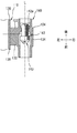
上記した遊技機の基板ボックス118では、図17に示すように、セット側の開封部122とカバー側の開封部132とが断面ほぼ長四角形状の帯板状にそれぞれ形成されている。
そして、封印状態において、各開封部122,132は、断面ほぼ長四角形状における長手方向が両連結部124,134の結合方向すなわち前後方向に延びるようにして一連状いわゆる直列状に並んでいる。
したがって、両連結部124,134の結合方向すなわち前後方向の延長線LE上、例えば前方からは、カバー側の開封部132は目視すなわち検査等の作業者の目Mで見ることができるが、セット側の開封部122はカバー側の開封部132の後方に隠れて見えない。
このため、セット側の開封部122のみを切断工具146によって切断することによって、その切断の痕跡がわかりにくく、不正の事実が発見されにくい状態で、基板ボックス118が不正に開封されてしまうおそれがあった。
【0008】
本発明は、上述の基板収納ボックス等の遊技機用部品収納ボックスにおける従来の封止手段に係る問題点を解決するものであり、その目的とするところは、防犯上の観点からボックス内部が一旦封止(密閉)された後には外部から不正に再開放されないことを実現するカバーと筐体本体部との封止手段、および、そのような封止手段によって密閉された遊技機用部品ボックスを提供することである。
【0009】
【課題を解決するための手段】
前記課題は、本発明の特許請求の範囲の欄に記載された構成を要旨とする遊技機の基板ボックスにより解決することができる。
すなわち、特許請求の範囲の請求項1に記載された遊技機の基板ボックスによると、セット部材にカバー部材が閉じられ、遊技機における制御基板が収容される。
そして、セット部材とカバー部材に設けられた各連結部は、相互に封印状態に結合される。
また、前記封印を解くすなわち開封する場合には、開封部を工具によって切断する。
その開封部の切断時に際し、切除部が切除される。
したがって、切除部の切除による痕跡を残さずに開封部を切断することがむつかしいことと、その切除部の切除の痕跡を目視によって容易に発見し得ることの相乗効果によって、不正な開封を抑制することができる。
また、開封部の切断時に際し、切除部を切除することにより、開封部の切断が補助されるので、その開封部の切断を容易に行うことができる。
さらに、切除部を切除することによって開口された開口部に工具を挿入して、その開口部から開封部を容易に切断することができる。
【0010】
【0011】
【0012】
【0013】
【0014】
【0015】
【0016】
【発明の実施の形態】
[実施の形態1]本発明の実施の形態1を説明する。
本実施の形態では、遊技機の一つであるパチンコ機に本発明を適用したものを例示する。
まず、基板ボックスの説明に先だって、パチンコ機の基本的な構成を述べる。
なお、パチンコ機の基本的な構成は、周知のパチンコ機とほとんど同様であるから簡単に述べるにとどめる。
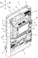
図1はパチンコ機を後方側から見た斜視図である。
また、パチンコ機の方位は、図1に矢印で示すように定める。
【0017】
図1において、パチンコ機1は、外枠体2と前枠4と遊技盤ユニット16を備えている。
外枠体2は、ほぼ矩形枠状に形成されている。
前枠4は、ほぼ額縁状に形成されており、外枠体2の前面側(正面側という)にヒンジ機構3によって開閉可能に設けられている。
前枠4の後面側(背面側という)には、ほぼ矩形枠状の支持枠6が設けられている。
【0018】
前記遊技盤ユニット16は、前記支持枠6に対しその後面側から取外し可能に嵌込まれた後、裏セット部材8によって固定されている。
裏セット部材8は、前枠4の後面側にヒンジ機構(図示省略)によって開閉可能に設けられている。
裏セット部材8の開閉側端部は、支持枠6に設けられた複数の留め具7によって閉じた状態に保持されている。
遊技盤ユニット16は、その前面側に遊技盤(図示省略)を備えている。
遊技盤の前面側には、図示しないが、球案内レール、遊技構成部材としての各種の入賞装置、役物装置、図柄表示装置、アタッカ装置、ゲート口、風車器、誘導釘等が配設されている。
【0019】
前記裏セット部材8の後面側には、球タンク9、タンクレール10、球払出装置12、電源基板ボックス14等が設けられている。
電源基板ボックス14内には、図示しないが、外部電源を所要の電圧に調整するための電子部品が実装された電源基板が収容されている。
【0020】
前記前枠4の前面側には、図示しないが、遊技盤の遊技領域を透視可能とする透視板を有する表枠5が設けられている。
また、前枠4の前面側には、上皿を有する下板、下皿等が設けられている。
また、前枠4の下端部には、球発射用の発射ハンドル装置13が設けられている。
【0021】
前記遊技盤ユニット16の後面側には、裏カバー体15が設けられている。
裏カバー体15の後面側には、主基板ボックス18と副基板ボックス19が設けられている。
各基板ボックス18,19には、それぞれ所要の電子部品が実装された制御基板(図示省略)が収容されている。
【0022】
次に、封印手段(後述する)を備えた主基板ボックス18について詳述する。
主基板ボックス18は、本発明が対象とする基板ボックスに相当しているため、単に「基板ボックス」ともいう。
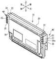
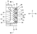
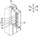
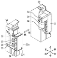
図2は基板ボックスを示す斜視図、図3は基板ボックスを示す正面図である。
なお、説明の都合上、基板ボックス18の方位は、図2および図3に矢印で示すように定める。
このため、基板ボックス18の前後左右は、パチンコ機1(図1参照)の前後左右とは逆向きになっている。
【0023】
図2に示すように、基板ボックス18は、セット部材20と、そのセット部材20にヒンジ手段(図示省略)によって開閉可能に設けられたカバー部材30とを備えた薄型のボックス状に形成されている。
基板ボックス18内には、遊技機(図1参照)における制御基板(図示省略)が収容されている。
セット部材20およびカバー部材30は、合成樹脂成形品によって形成されている。
なお、基板ボックス18は、前記裏カバー体15に取外し可能に設けられている。
また、図示しないが、制御回路の前面側には、前記遊技盤(図示省略)に配設された入賞装置、役物装置、図柄表示装置、アタッカ装置等の作動を制御するための回路素子いわゆる電子部品が実装されている。
【0024】
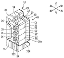
図2および図3に示すように、前記セット部材20と前記カバー部材30との間には、そのセット部材20に対しカバー部材30を閉じた状態に封印するための左右の封印手段40が設けられている。
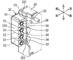
なお、図4は右側に配置された基板ボックスの封印手段を示す斜視図、図5は同じく正面図、図6は図5のVI−VI線断面図、図7は封印手段の未封印状態を示す図6に準じる断面図、図8は図5のVIII−VIII線断面図である。
さらに、図9はセット側の連結部を示す斜視図、図10はカバー側の連結部の裏面を示す斜視図、図11はカバー側の連結部の裏面図である。
【0025】
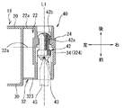
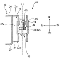
図7に示すように、前記封印手段40は、セット部材20側(セット側と略す)の連結部24とカバー部材30側(カバー側と略す)の連結部34とかしめ部材42と封印ねじ43とを備えている。
以下、順に述べる。
セット側の連結部24は、図9に示すように、ほぼ筒形状に形成されており、前記セット部材20の外側面に形成されたほぼ四角形枠状の支持部(セット側の支持部という)22内に上下方向に適数個(例えば、4個)並んで連設されている。
セット側の支持部22と連結部24とは相互に接続する部分を共有している。
また、支持部22は、図8に示すように、その後面の開口を覆う後板部22aを有している。
セット側の支持部22および連結部24は、セット部材20に一体成形によって形成されている。
【0026】
前記カバー側の連結部34は、図10および図11に示すように、ほぼ筒形状に形成されており、前記カバー部材30に形成されたほぼ四角形箱状の開封部(カバー側の開封部という)32内に上下方向に適数個(例えば、4個)並んで連設されている。
すなわち、カバー部材30には、開封部32を介して連結部34が設けられている。
カバー側の開封部32および連結部24は、カバー部材30に一体成形によって形成されている。
なお、カバー側の開封部32については後で詳述する。
【0027】
前記各セット側の連結部24とそれに対応する各カバー部材30側の連結部34とは、セット部材20にカバー部材30を閉じた状態において、それぞれ前後方向に延びる軸線L1(図7参照)上に並んでいる。
すなわち、各セット側の連結部24の前側に、対応するカバー部材30側の連結部34が並んでいる。
【0028】
図7に示すように、前記かしめ部材42は、中空のリベット状に形成されており、カバー部材30側の連結部34内に挿入されて回り止めされた状態に配置されている。
かしめ部材42の先端部42aは、セット側の連結部24内に突出されているとともに、その内径を小さい口径とする絞り部42bを有している。
かしめ部材42は、塑性変形可能な金属材料によって形成されている。
【0029】
図7に示すように、前記封印ねじ43は、一方向ねじ(ワンウエイねじとも呼ばれている)からなり、前記カバー側の連結部34側より前記かしめ部材42内にねじ込まれている。
封印ねじ43は、締付け方向に関してはドライバー等の締付け工具45(図6参照)によりねじ込むことができるが、緩め方向に関しては緩めることができない構成のねじである。
【0030】
前記封印ねじ43が、図7の状態から図6に示すように、ドライバー等の締付け工具45によりかしめ部材42内にねじ込まれる。
この封印ねじ43のねじ込みによって、かしめ部材42の絞り部42bが押し広げられることにより、該かしめ部材42の先端部42aが外径を大きくする方向へ塑性変形されて、セット側の連結部24にかしめつけられる。
これによって、セット部材20にカバー部材30が閉じた状態に固定すなわち封印されている。
なお、封印ねじ43による封印は、カバー部材30の複数の連結部34(図5参照)のうちから選択的に実施される。
本実施の形態の場合、カバー部材30の最上段の連結部34(図5参照)から行われ、その封印が解除されたならばその下の連結部34で行われ、順次下方へ向かって行われるものとする。
また、各連結部24,34の軸線L1(図6参照)方向すなわち前後方向が、本明細書でいう「両連結部の結合方向」に相当する。
【0031】
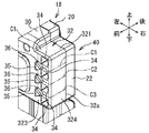
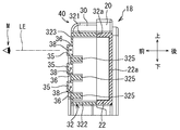
次に、前記カバー部材30の開封部32について詳述する。
図10および図11に示すように、前記カバー側の開封部32は、上側板部321、下側板部322、前板部323(図5参照)および外側板部324を有している。
上側板部321および下側板部322は、カバー部材30の本体部(符号省略)に連続している。
また、図5に示すように、前板部323は、カバー部材30の本体部(符号省略)に連続しかつ上側板部321および下側板部322に上下の端縁部が連続している(図10参照)。
【0032】
図10および図11に示すように、前記外側板部324は、上側板部321および下側板部322に上下の端縁部が連続しかつ前板部323(図5参照)に前縁部が連続している。
カバー側の開封部32と連結部34とは相互に接続する部分を共有している。
カバー側の連結部34は、開封部32の前板部323および外側板部324による連続部分を除いて相互に所定の間隔S1(図10参照)を隔てて形成されている。
また、カバー側の連結部34とカバー部材30とは、開封部32の前板部323、上側板部321および下側板部322による連続部分を除いて所定の間隔S2(図10参照)を隔てて形成されている。
【0033】
図11に示すように、最上段のカバー側の連結部34を除く連結部34とカバー部材30との間には、それぞれ補助板部325が架設されている。
各補助板部325は、図8に示すように、開封部32の前板部323に連続しかつ開封部32の前半部に形成されている。
【0034】
図8に示すように、前記カバー側の開封部32の裏面すなわち開口端面(符号、32aを付す)は、前記セット部材20の支持部22に対し面接触されることによって閉止されている。
なお、カバー側の開封部32の開口端面32aは、セット部材20に対するカバー部材30の開閉によって、セット部材20の支持部22に対し離れたり面接触したりする。
【0035】
図4および図10に示すように、前記カバー側の開封部32には、最上段から下段側へのカバー側の連結部34を取り囲むようにして、ニッパー、カッター等の工具(図示省略)によって切断可能な第1〜第3の切断経路(各図には仮想線で示す)C1,C2,C3が設定されている。
また、本実施の形態の場合、第1〜第3の切断経路C1,C2,C3は、切断を想定した経路を示すものであり、表示機能を有するものではない。
しかし、切断経路C1,C2,C3を表示する手段、例えば、シール部材、突起部、凹み部等を設けることにより、切断経路C1,C2,C3を明確に表示するとよい。
【0036】
前記第1の切断経路C1は、最上段のカバー側の連結部34を独立的に仕切るように、前記カバー側の開封部32の上側板部321、前板部323および外側板部324にわたって設定されている。
前記第2の切断経路C2は、第1の切断経路C1とともに、上から2段目の連結部34を独立的に仕切るように、カバー側の開封部32の前板部323および外側板部324にわたって設定されている。
前記第3の切断経路C3は、第2の切断経路C2とともに、上から3段目の連結部34を独立的に仕切るように、カバー側の開封部32の前板部323および外側板部324にわたって設定されている。
また、各切断経路C1,C2,C3が想定されるカバー側の開封部32の上側板部321、前板部323および外側板部324の当該部分は、ニッパー、カッター等の工具により切断可能な板厚をもって形成されている。
なお、最下段のカバー側の連結部34については、最終的に封印されるもので切断する必要がないため、切断経路が設定されていない。
【0037】
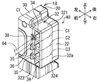
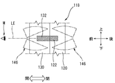
図4に示すように、前記カバー側の開封部32の前板部323には、前記カバー側の連結部34の相互間で前記各切断経路C1,C2,C3上に位置するほぼ三角形状の切除部35が隆起状に設けられている。
各切除部35は、両連結部24,34の結合方向の延長線LE上、例えば前方から目視すなわち検査等の作業者の目Mで見ることができる(図8参照)。
【0038】
図8に示すように、前記切除部35は、前記カバー側の開封部32の前板部323に対しほぼ三角形筒状の脆弱部36を介して連設されている。
脆弱部36は、切除部35よりも薄い肉厚とされることにより脆弱性が付与されている。
脆弱部36の切断あるいは破壊等によって、切除部35が切除可能になっている。
【0039】
前記切除部35は、図8に示すように、開封部32の前板部323に形成されるほぼ三角形状の開口部38を覆っている。
したがって、切除部35が切除されることにより、開口部38が開口される(図12参照)。
【0040】
また、図5に示すように、前記切除部35の三角形状の1つの頂点部は外側方に指向され、残りの2つの頂点部は上下方向にほぼ一直線上に並ぶようにして形成されている。
すなわち、切除部35の各頂点部は、それぞれ各切断経路C1,C2,C3の切断方向を表示している。
なお、切除部35は本明細書でいう「開封部に設けられた表示手段」を兼ねている。
【0041】
上記した遊技機の基板ボックス18によると、セット部材20にカバー部材30が閉じられ、遊技機における制御基板(図示省略)が収容される。
そして、セット部材20とカバー部材30に設けられた各連結部24,34は、かしめ部材42に対する封印ねじ43のねじ込みによって、所定の結合方向すなわち前後方向に関し相互に封印状態に結合される(図6参照)。
【0042】
また、基板ボックス18内の検査等に際し封印を解くすなわち開封する場合には、まず、封印されたカバー部材30の連結部34に対応する切除部35、例えば最上段の切除部35を切除する。
このとき、例えば、切除部35の脆弱部36をニッパー、カッター等で切断したり、あるいは切除部35を叩いたりこじたり等して破壊させたりすることによって、容易に切除部35を除去することができる(図12参照)。
切除部35が切除された状態では、カバー部材30の開封部32の前板部323に開口部38が開口される。
【0043】
次に、カバー部材30の開封部32の前板部323に開口された開口部38に、例えば、ニッパー、カッター等の工具(図12中、二点鎖線64参照)を挿入、詳しくは先端部を挿入する。
そして、開口部38から二方向の第1の切断経路C1に沿って開封部32を切断する。
これによって、封印手段40の封印を開封することができ、カバー部材30を開閉することができる(図13参照)。
【0044】
そして、再び、前記基板ボックス18を封印する場合には、セット部材20にカバー部材30を閉じた状態で、開封されていない連結部34、すなわち上から2段目のカバー側の連結部34における封印ねじ43をかしめ部材42にねじ込めばよい(図6参照)。
すると、前に述べたように、かしめ部材42の塑性変形を利用して、上から2段目のセット側の連結部24とカバー側の連結部34とが閉じた状態に固定されて封印される。
【0045】
また、次回、開封する場合には、上から2段目の切除部35を切除したのち、上記と同様にして、第2の切断経路C2(図12参照)に沿って開封部32を切断すればよい。
そして、セット部材20にカバー部材30を閉じた状態で、上から3段目のカバー側の連結部34における封印ねじ43をねじ込むことにより、基板ボックス18を封印することができる。
【0046】
また、次回、開封する場合には、上から3段目の切除部35を切除したのち、上記と同様にして、第3の切断経路C3(図4参照)に沿って開封部32を切断すればよい。
そして、セット部材20にカバー部材30を閉じた状態で、上から4段目のカバー側の連結部34における封印ねじ43をねじ込むことにより、基板ボックス18を封印することができる。
【0047】
上記した遊技機の基板ボックスによれば、カバー部材30の開封部32の切断に際し、切除部35(図4参照)が切除される。
本実施の形態では、切除部35を切除しなければならない。
したがって、切除部35の切除による痕跡を残さずに開封部32を切断することがむつかしいことと、その切除部35の切除の痕跡を目視によって容易に発見し得ることの相乗効果によって、不正な開封を抑制することができる。
また、開封部32の切断時に際し、切除部35を切除することにより、開封部32の切断が補助されるので、その開封部35の切断を容易に行うことができる。
【0048】
また、カバー部材30の開封部32が開口端面32aを有するほぼ箱状に形成され、その開封部32の開口端面32aがセット部材20の支持部22によって閉止されている(図4および図8参照)。
これにより、開封部32を開口端面32aから切断することがむつかしくなるとともに、開封部32の切断距離が長くとれるため、その開封部32の切断の痕跡を目視によって容易に発見し得ることによって、不正な開封の抑制効果を向上することができる。
【0049】
また、カバー部材30の切除部35が両連結部24,34の結合方向の延長線LE(図8参照)上からの目視により、切除部35の切除の痕跡を容易に発見することができる。
【0050】
また、切除部35が有する脆弱部36(図8参照)を容易に破壊させることができるので、切除部35の除去を容易に行うことができる。
【0051】
また、切除部35を切除することによって開口された開口部38に工具等46を挿入して、その開口部38から開封部32を容易に切断することができる(図12参照)。
【0052】
また、カバー部材30の開封部32に設けられた表示手段を兼ねる切除部35によって、切断経路C1,C2,C3が表示されるので、その切断経路C1,C2,C3に沿って開封部32を確実かつ容易に切断することができる。
【0053】
[実施の形態2]本発明の実施の形態2を説明する。
実施の形態2は、上記した実施の形態1の一部に変更を加えたものであるからその変更部分について詳述し、重複する説明は省略する。
図14は基板ボックスの封印手段を示す斜視図である。
【0054】
図14に示すように、カバー部材30の開封部32の上側板部321および外側板部324の開口端面30aには、前記各切断経路C1,C2,C3上にそれぞれ位置するほぼV字溝状の切込み溝39が形成されている。
各切込み溝39の溝底側の頂部は、各切断経路C1,C2,C3の切断方向を表示している。
また、各切込み溝39は、前記開口部38(図12参照)と同様に、例えば、ニッパー、カッター等の工具(図12中、二点鎖線64参照)を挿入可能に形成されている。
なお、切込み溝39は本明細書でいう「開封部に設けられた表示手段」および「凹部」に相当する。
【0055】
上記した実施の形態2の遊技機の基板ボックス18によっても、実施の形態1と同様の作用効果を得ることができる。
また、カバー部材30の開封部32に設けられた表示手段である切込み溝39によって、切断する切断経路C1,C2,C3が表示されるので、その切断経路C1,C2,C3に沿って開封部32を確実かつ容易に切断することができる。
また、表示手段である切込み溝39にニッパー、カッター等の工具を挿入可能としたことによって、切込み溝39からの開封部32の補助的な切断が可能である。
【0056】
本発明は上記した実施の形態に限定されるものではなく、本発明の要旨を逸脱しない範囲における変更が可能である。
例えば、本発明は、主基板ボックス18に限らず、副基板ボックス19、その他の基板ボックスにも適用することができる。
また、前記した実施の形態においては、遊技機がパチンコ機1である場合を例示したが、これに限定するものではなく、例えば、アレンジボール機、雀球機、スロットマシン等の遊技機に対しても適用することができる。
また、封印手段40は、セット側の連結部24とカバー側の連結部34とを封印可能であればよく、前記実施の形態の封印ねじ43を利用するものに限定されるものではない。
【0057】
また、切除部35は、開封部32の切断に際して切除されるものであればよく、その切除部35の形状は、三角形状に限らず、例えば、四角形状、丸形状、L字形状、T字形状等に代えてもよいし、また、その大きさも、配置位置も適宜選定することができる。
また、切除部35は、開口部38を全面的に覆うものに限らず、部分的覆うバー状、格子状、突片状等でもよいし、また、切除部35が切除されたか否かが識別できれば開口部38が省略されていてもよい。
また、切除部35は、切除可能であればよく、脆弱部36の有無は限定されない。
また、切除部35は、基板ボックス18の前方以外でも目視可能な外観上に設けられていればよい。
また、カバー部材30の開封部32の形状も、開口端面がセット部材20の支持部22によって閉止されない形状であってもよい。
また、セット部材20に、カバー部材30の切除部35を設けた開封部32とほぼ同様の開封部32を設けることもできる。
また、表示手段としては、上記した切除部35および/または切込み溝39に限らず、切断経路を表示できるものであれば、例えば、直線、ドット、ミシン目状等の突起部または凹み部あるいはシール部材等に代えてもよい。
【0058】
【発明の効果】
以上、詳述したように、本発明によれば、切除部の切除による痕跡を残さずに開封部を切断することがむつかしいことと、その切除部の切除の痕跡を目視によって容易に発見し得ることの相乗効果によって、不正な開封を抑制することができる。
【図面の簡単な説明】
【図1】 本発明の実施の形態1にかかるパチンコ機を後方側から見た斜視図である。
【図2】基板ボックスを示す斜視図である。
【図3】基板ボックスを示す正面図である。
【図4】基板ボックスの封印手段を示す斜視図である。
【図5】基板ボックスの封印手段を示す正面図である。
【図6】図5のVI−VI線断面図である。
【図7】封印手段の未封印状態を示す図6に準じる断面図である。
【図8】図5のVIII−VIII線断面図である。
【図9】セット側の連結部を示す斜視図である。
【図10】カバー側の連結部の裏面を示す斜視図である。
【図11】カバー側の連結部の裏面図である。
【図12】切除部が切除された状態の封印手段を示す斜視図である。
【図13】カバー部材を開いた状態の封印手段を開放状態で示す斜視図である。
【図14】本発明の実施の形態2にかかる基板ボックスの封印手段を示す斜視図である。
【図15】従来の技術にかかる基板ボックスの封印手段を示す正面図である。
【図16】図15のXVI−XVI線断面図である。
【図17】図15のXVII−XVII線断面図である。
【符号の説明】
1 パチンコ機(遊技機)
18 基板ボックス
20 セット部材
24 セット側の連結部
30 カバー部材
32 カバー側の開封部
32a 開口端面
34 カバー側の連結部
35 切除部(表示手段を兼ねる)
36 脆弱部
38 開口部
39 切込み溝(表示手段、凹部)
C1,C2,C3 切断経路[0001]
BACKGROUND OF THE INVENTION
The present invention relates to a board box of a gaming machine such as a pachinko machine, an arrange ball machine, a sparrow ball machine, a throttle machine and the like.
[0002]
[Prior art]
For example, a gaming machine such as a pachinko machine installed in a gaming hall or the like is provided with a “board box” that houses a control board (also called a circuit board) on which electronic components are mounted.
This type of board box is provided with sealing means for preventing illegal actions such as illegally replacing electronic components inside the ROM, such as ROM, or illegally rewriting the contents stored in the ROM. ing.
[0003]
Next, a conventional example of a substrate box provided with sealing means will be described with reference to the drawings.
15 is a front view showing the sealing means of the substrate box, FIG. 16 is a sectional view taken along line XVI-XVI in FIG. 15, and FIG. 17 is a sectional view taken along line XVII-XVII in FIG.
As shown in FIGS. 16 and 17, the
In an internal space formed by the
[0004]
As shown in FIG. 16, sealing means 140 is provided between the
The sealing means 140 includes a connecting
The set-
The cover-
The set-
[0005]
As shown in FIG. 16, the
A
The sealing
By screwing in the sealing
Accordingly, the
[0006]
By the way, in the case of inspection or the like in the
Accordingly, the
Moreover, it can be easily confirmed visually that the
[0007]
[Problems to be solved by the invention]
In the above-described
In the sealed state, the
Therefore, the
For this reason, by cutting only the
[0008]
The present invention solves the problems associated with the conventional sealing means in the above-mentioned board storage box and other parts storage boxes for gaming machines, and the purpose of the present invention is to temporarily store the inside of the box from the viewpoint of crime prevention. After sealing (sealing), there is provided a sealing means for the cover and the housing main body that prevents unauthorized reopening from the outside, and a gaming machine parts box sealed by such sealing means. Is to provide.
[0009]
[Means for Solving the Problems]
The above-mentioned problems can be solved by a board box of a gaming machine having the gist of the configuration described in the claims of the present invention.
That is, according to the board box of the gaming machine described in
And each connection part provided in the set member and the cover member is mutually couple | bonded in the sealing state.
When opening the seal, that is, when opening the seal,IngredientsTherefore, cut.
When the opening portion is cut, the excision portion is excised.
Therefore, it is difficult to cut the opening part without leaving a trace due to the excision of the excision part, and it is easy to visually detect the excision trace of the excision part, thereby suppressing unauthorized opening. be able to.
Moreover, since the cutting of the opening portion is assisted by cutting the excision portion at the time of cutting the opening portion, the opening portion can be easily cut.
Furthermore, a tool can be inserted in the opening part opened by excising a cutting part, and an opening part can be easily cut | disconnected from the opening part.
[0010]
[0011]
[0012]
[0013]
[0014]
[0015]
[0016]
DETAILED DESCRIPTION OF THE INVENTION
[Embodiment 1]
In this embodiment, an example in which the present invention is applied to a pachinko machine that is one of gaming machines is illustrated.
First, before explaining the board box, the basic configuration of the pachinko machine will be described.
The basic configuration of a pachinko machine is almost the same as that of a known pachinko machine, so only a brief description will be given.
FIG. 1 is a perspective view of a pachinko machine viewed from the rear side.
Also, the orientation of the pachinko machine is determined as shown by the arrow in FIG.
[0017]
In FIG. 1, the
The
The
A substantially rectangular frame-shaped
[0018]
The
The back set
The open / close end of the back set
The
On the front side of the game board, although not shown, a ball guide rail, various winning devices as game components, an accessory device, a symbol display device, an attack device, a gate port, a windmill, a guide nail, etc. are arranged. ing.
[0019]
On the rear surface side of the back set
Although not shown, the power
[0020]
On the front side of the
Further, on the front side of the
Further, a
[0021]
A
On the rear surface side of the
Each of the
[0022]
Next, the
Since the
FIG. 2 is a perspective view showing the substrate box, and FIG. 3 is a front view showing the substrate box.
For convenience of explanation, the orientation of the
For this reason, the front, rear, left and right of the
[0023]
As shown in FIG. 2, the
A control board (not shown) in the gaming machine (see FIG. 1) is accommodated in the
The
The
Although not shown, a circuit element for controlling the operation of a winning device, an accessory device, a symbol display device, an attacker device, etc. disposed on the game board (not shown) is provided on the front side of the control circuit. Electronic components are mounted.
[0024]
As shown in FIGS. 2 and 3, left and right sealing means 40 are provided between the
4 is a perspective view showing the sealing means of the substrate box arranged on the right side, FIG. 5 is also a front view, FIG. 6 is a sectional view taken along the line VI-VI in FIG. 5, and FIG. 7 is an unsealed state of the sealing means. FIG. 8 is a sectional view according to FIG. 6 and FIG. 8 is a sectional view taken along line VIII-VIII in FIG.
9 is a perspective view showing the connecting portion on the set side, FIG. 10 is a perspective view showing the back surface of the connecting portion on the cover side, and FIG. 11 is a back view of the connecting portion on the cover side.
[0025]
As shown in FIG. 7, the sealing means 40 includes a connecting
Hereinafter, it will be described in order.
As shown in FIG. 9, the set-
The
Moreover, the
The
[0026]
As shown in FIGS. 10 and 11, the cover-
That is, the
The cover-
The cover
[0027]
Each set-
That is, the corresponding connecting
[0028]
As shown in FIG. 7, the
The
The
[0029]
As shown in FIG. 7, the sealing
The sealing
[0030]
As shown in FIG. 6, the sealing
When the sealing
Accordingly, the
The sealing with the sealing
In the case of the present embodiment, it is carried out from the uppermost connecting portion 34 (see FIG. 5) of the
In addition, the direction of the axis L1 (see FIG. 6) of each of the connecting
[0031]
Next, the opening
As shown in FIGS. 10 and 11, the cover-
The
Further, as shown in FIG. 5, the
[0032]
As shown in FIGS. 10 and 11, the outer
The opening
The connecting
Further, the cover
[0033]
As shown in FIG. 11,
As shown in FIG. 8, each
[0034]
As shown in FIG. 8, the back surface, that is, the opening end surface (reference numeral 32 a) of the opening
Note that the opening
[0035]
As shown in FIGS. 4 and 10, the opening
In the case of the present embodiment, the first to third cutting paths C1, C2, and C3 indicate paths that are assumed to be cut and do not have a display function.
However, the cutting paths C1, C2, and C3 may be clearly displayed by providing a means for displaying the cutting paths C1, C2, and C3, for example, a seal member, a protrusion, a recess, and the like.
[0036]
The first cutting path C1 is set over the
The second cutting path C2 and the first cutting path C1 together with the first cutting path C1 independently divide the second-
The third cutting path C3 and the second cutting path C2 together with the
Further, the
In addition, about the
[0037]
As shown in FIG. 4, the
Each cutting
[0038]
As shown in FIG. 8, the
The
The
[0039]
As shown in FIG. 8, the
Accordingly, the
[0040]
Further, as shown in FIG. 5, one triangular vertex of the
That is, each vertex part of the cutting
The
[0041]
According to the
The connecting
[0042]
Further, when the seal is released, that is, when the
At this time, for example, the
In the state where the
[0043]
Next, for example, a tool such as a nipper or a cutter (see a two-
And the opening
Thereby, the seal of the sealing means 40 can be opened, and the
[0044]
When the
Then, as described above, using the plastic deformation of the
[0045]
Further, when opening the next time, after cutting the
Then, the
[0046]
Further, when opening the next time, after cutting the
The
[0047]
According to the above-described board box of the gaming machine, when the opening
In the present embodiment, the
Therefore, it is difficult to cut the unsealed
Further, when the opening
[0048]
Further, the opening
As a result, it becomes difficult to cut the opening
[0049]
Further, the
[0050]
Moreover, since the weak part 36 (refer FIG. 8) which the cutting
[0051]
Moreover, the tool etc. 46 can be inserted in the
[0052]
Further, since the cutting paths C1, C2, and C3 are displayed by the cutting
[0053]
[Embodiment 2]
Since the second embodiment is obtained by changing a part of the first embodiment described above, the changed portion will be described in detail, and a duplicate description will be omitted.
FIG. 14 is a perspective view showing the sealing means of the substrate box.
[0054]
As shown in FIG. 14, the upper
The top of each cut
Each
The
[0055]
The same effect as that of the first embodiment can be obtained also by the
Further, since the cutting paths C1, C2, and C3 to be cut are displayed by the
Further, by making it possible to insert a tool such as a nipper or a cutter into the
[0056]
The present invention is not limited to the above-described embodiments, and modifications can be made without departing from the gist of the present invention.
For example, the present invention can be applied not only to the
Further, in the above-described embodiment, the case where the gaming machine is the
Moreover, the sealing means 40 should just be able to seal the
[0057]
In addition, the
In addition, the
The
Moreover, the
Further, the shape of the opening
Further, the
Further, the display means is not limited to the above-described
[0058]
【The invention's effect】
As described above in detail, according to the present invention, it is difficult to cut the opening part without leaving a trace due to the excision of the excision part, and the excision trace of the excision part can be easily found by visual observation. Due to this synergistic effect, unauthorized opening can be suppressed.
[Brief description of the drawings]
FIG. 1 is a perspective view of a pachinko machine according to a first embodiment of the present invention as viewed from the rear side.
FIG. 2 is a perspective view showing a substrate box.
FIG. 3 is a front view showing a substrate box.
FIG. 4 is a perspective view showing a sealing means for a substrate box.
FIG. 5 is a front view showing a sealing means for a substrate box.
6 is a cross-sectional view taken along line VI-VI in FIG.
7 is a cross-sectional view according to FIG. 6 showing an unsealed state of the sealing means.
8 is a cross-sectional view taken along line VIII-VIII in FIG.
FIG. 9 is a perspective view showing a connecting portion on the set side.
FIG. 10 is a perspective view showing the back surface of the connecting portion on the cover side.
FIG. 11 is a rear view of the connecting portion on the cover side.
FIG. 12 is a perspective view showing the sealing means in a state where the excision part is excised.
FIG. 13 is a perspective view showing the sealing means with the cover member opened in an open state.
FIG. 14 is a perspective view showing sealing means for a substrate box according to the second embodiment of the present invention.
FIG. 15 is a front view showing a sealing means for a substrate box according to the prior art.
16 is a cross-sectional view taken along line XVI-XVI in FIG.
17 is a cross-sectional view taken along line XVII-XVII in FIG.
[Explanation of symbols]
1 Pachinko machine (game machine)
18 Board box
20 set members
24 Connecting part on the set side
30 Cover member
32 Opening part on the cover side
32a Open end face
34 Cover side connection
35 Cut section (also serves as a display)
36 Vulnerable parts
38 opening
39 Cutting groove (display means, recess)
C1, C2, C3 cutting path
Claims (1)
前記セット部材と前記カバー部材には、相互に封印状態に結合される各連結部が設けられ、前記セット部材と前記カバー部材のうち少なくとも一方の部材には、工具によって切断可能な開封部を介して前記連結部が設けられ、前記開封部には、切断を補助する切除部が切除可能に設けられ、前記切除部の切除により、工具を挿入可能となる開口部が設けられることで、前記開封部を切断可能にすることを特徴とする遊技機の基板ボックス。A board box for a gaming machine comprising a set member and a cover member provided on the set member so as to be opened and closed, and configured to accommodate a control board in the gaming machine,
Wherein the setting member and the cover member, another the connecting portion is provided that is coupled to a sealed state, at least one member of the set member and the cover member, Engineering again and again thus cleavable unsealing portion The connecting part is provided via, and the opening part is provided with an excision part that assists cutting, and an opening part through which the tool can be inserted by excision of the excision part is provided. A board box for a gaming machine, characterized in that the opening portion can be cut .
Priority Applications (1)
| Application Number | Priority Date | Filing Date | Title |
|---|---|---|---|
| JP2002069009A JP4092425B2 (en) | 2002-03-13 | 2002-03-13 | Gaming machine board box |
Applications Claiming Priority (1)
| Application Number | Priority Date | Filing Date | Title |
|---|---|---|---|
| JP2002069009A JP4092425B2 (en) | 2002-03-13 | 2002-03-13 | Gaming machine board box |
Publications (2)
| Publication Number | Publication Date |
|---|---|
| JP2003265808A JP2003265808A (en) | 2003-09-24 |
| JP4092425B2 true JP4092425B2 (en) | 2008-05-28 |
Family
ID=29199979
Family Applications (1)
| Application Number | Title | Priority Date | Filing Date |
|---|---|---|---|
| JP2002069009A Expired - Lifetime JP4092425B2 (en) | 2002-03-13 | 2002-03-13 | Gaming machine board box |
Country Status (1)
| Country | Link |
|---|---|
| JP (1) | JP4092425B2 (en) |
Families Citing this family (8)
| Publication number | Priority date | Publication date | Assignee | Title |
|---|---|---|---|---|
| JP2006130185A (en) * | 2004-11-09 | 2006-05-25 | Sanyo Product Co Ltd | Controlling unit for game machine, and game machine |
| JP4916800B2 (en) * | 2006-07-13 | 2012-04-18 | 株式会社大一商会 | Pachinko machine |
| JP4909664B2 (en) * | 2006-07-21 | 2012-04-04 | 株式会社大一商会 | Pachinko machine |
| JP5033947B2 (en) * | 2006-07-28 | 2012-09-26 | 株式会社大一商会 | Pachinko machine |
| JP4692685B2 (en) * | 2010-04-26 | 2011-06-01 | 株式会社三洋物産 | Game machine |
| JP5164293B2 (en) * | 2010-09-10 | 2013-03-21 | サミー株式会社 | Game machine |
| JP4692690B2 (en) * | 2010-09-29 | 2011-06-01 | 株式会社三洋物産 | Game machine |
| JP4692689B2 (en) * | 2010-09-29 | 2011-06-01 | 株式会社三洋物産 | Game machine |
-
2002
- 2002-03-13 JP JP2002069009A patent/JP4092425B2/en not_active Expired - Lifetime
Also Published As
| Publication number | Publication date |
|---|---|
| JP2003265808A (en) | 2003-09-24 |
Similar Documents
| Publication | Publication Date | Title |
|---|---|---|
| JP5950187B2 (en) | Game machine | |
| JP4092425B2 (en) | Gaming machine board box | |
| JP5166595B2 (en) | Game machine | |
| JP4092426B2 (en) | Gaming machine board box | |
| JP4183458B2 (en) | Seal structure | |
| JP2003245450A (en) | Game machine | |
| JP2010220645A (en) | Game machine | |
| JP5656033B2 (en) | Game machine | |
| JP4092427B2 (en) | Gaming machine board box | |
| JP2001087520A (en) | Control box device for game machine | |
| JP5415346B2 (en) | Board case for gaming machines | |
| JP2003236196A (en) | Board box for game machine | |
| JP5979410B2 (en) | Game machine | |
| JP2006111307A (en) | Box with illegal unsealing preventive function | |
| JP5648817B2 (en) | Game machine | |
| JP2019209209A (en) | Game machine | |
| JP2006198116A (en) | Substrate case for game machine | |
| JP5927741B2 (en) | Game machine | |
| JP2013192663A (en) | Game machine | |
| JP5756838B2 (en) | Slot machine | |
| JP6288194B2 (en) | Game machine | |
| JP6332352B2 (en) | Game machine | |
| JP5788479B2 (en) | Game machine | |
| JP6245298B2 (en) | Game machine | |
| JP2002204876A (en) | Circuit board closing structure for game machine |
Legal Events
| Date | Code | Title | Description |
|---|---|---|---|
| A621 | Written request for application examination |
Free format text: JAPANESE INTERMEDIATE CODE: A621 Effective date: 20050311 |
|
| A131 | Notification of reasons for refusal |
Free format text: JAPANESE INTERMEDIATE CODE: A131 Effective date: 20071030 |
|
| A521 | Request for written amendment filed |
Free format text: JAPANESE INTERMEDIATE CODE: A523 Effective date: 20071227 |
|
| TRDD | Decision of grant or rejection written | ||
| A01 | Written decision to grant a patent or to grant a registration (utility model) |
Free format text: JAPANESE INTERMEDIATE CODE: A01 Effective date: 20080205 |
|
| A61 | First payment of annual fees (during grant procedure) |
Free format text: JAPANESE INTERMEDIATE CODE: A61 Effective date: 20080214 |
|
| FPAY | Renewal fee payment (event date is renewal date of database) |
Free format text: PAYMENT UNTIL: 20110314 Year of fee payment: 3 |
|
| R150 | Certificate of patent or registration of utility model |
Free format text: JAPANESE INTERMEDIATE CODE: R150 Ref document number: 4092425 Country of ref document: JP Free format text: JAPANESE INTERMEDIATE CODE: R150 |
|
| R250 | Receipt of annual fees |
Free format text: JAPANESE INTERMEDIATE CODE: R250 |
|
| FPAY | Renewal fee payment (event date is renewal date of database) |
Free format text: PAYMENT UNTIL: 20140314 Year of fee payment: 6 |
|
| S531 | Written request for registration of change of domicile |
Free format text: JAPANESE INTERMEDIATE CODE: R313531 |
|
| FPAY | Renewal fee payment (event date is renewal date of database) |
Free format text: PAYMENT UNTIL: 20140314 Year of fee payment: 6 |
|
| R350 | Written notification of registration of transfer |
Free format text: JAPANESE INTERMEDIATE CODE: R350 |
|
| R250 | Receipt of annual fees |
Free format text: JAPANESE INTERMEDIATE CODE: R250 |
|
| R250 | Receipt of annual fees |
Free format text: JAPANESE INTERMEDIATE CODE: R250 |
|
| R250 | Receipt of annual fees |
Free format text: JAPANESE INTERMEDIATE CODE: R250 |
|
| R250 | Receipt of annual fees |
Free format text: JAPANESE INTERMEDIATE CODE: R250 |
|
| R250 | Receipt of annual fees |
Free format text: JAPANESE INTERMEDIATE CODE: R250 |
|
| R250 | Receipt of annual fees |
Free format text: JAPANESE INTERMEDIATE CODE: R250 |
|
| EXPY | Cancellation because of completion of term |