JP4091788B2 - Mechanical seal device - Google Patents
Mechanical seal device Download PDFInfo
- Publication number
- JP4091788B2 JP4091788B2 JP2002117390A JP2002117390A JP4091788B2 JP 4091788 B2 JP4091788 B2 JP 4091788B2 JP 2002117390 A JP2002117390 A JP 2002117390A JP 2002117390 A JP2002117390 A JP 2002117390A JP 4091788 B2 JP4091788 B2 JP 4091788B2
- Authority
- JP
- Japan
- Prior art keywords
- seal
- sealing
- ring
- inner peripheral
- peripheral surface
- Prior art date
- Legal status (The legal status is an assumption and is not a legal conclusion. Google has not performed a legal analysis and makes no representation as to the accuracy of the status listed.)
- Expired - Fee Related
Links
Images


Description
【0001】
【発明の属する技術分野】
本発明は、例えば、ポンプ、攪拌機、研磨機、ロータリージョイント等に用いられるメカニカルシール装置に関する。特に、スラリ−に硬質な粉末を含む流体をシールするのに適したメカニカルシール装置に関する。
【0002】
【従来の技術】
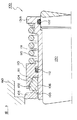
本発明の関連技術に関し、図3に示すメカニカルシール装置が存在する。図3はこのメカニカルシール100の半断面図である。
【0003】
図3に於いて、メカニカルシール100は、ハウジング160内の被密封流体をシールするために、ハウジング160と回転軸130との間に配置されている。このメカニカルシール100は、静止用密封環105の相対シール面106と回転用密封環102のシール面103が密接してシールするものである。
【0004】
静止用密封環105の外周面は、図示省略のOリングを介してハウジング160に固着されている。この静止用密封環105は炭化珪素又は超硬合金材製である。そして、一端の突出した面に相対シール面106が形成されている。又、静止用密封環105の内周面はスリーブ131との間に間隙が形成されている。
【0005】
一方、静止用密封環105に対向する回転用密封環102には、対向面にシール面103が形成されており、このシール面103が相対シール面106と密接している。又、回転用密封環102のシール面103と反対側にはテーパ面104が形成されている。この回転用密封環102のテーパ面104は、リテーナ110のテーパ嵌合面111に嵌合する。このテーパ嵌合面111は、回転用密封環102を覆うようにリテーナ110の先端内周面に設けられている。
そして、リテーナ110の内周面はスリーブ131の外周面に移動自在に嵌合して回転用密封環102を軸方向へ押圧できるように成されている。このスリーブ131は、回転用密封環102を回転させると共に保持するために、回転軸130に嵌着している。
【0006】
このスリーブ131の一端にはフランジ部131Aが設けられている。このフランジ部131Aにより支持されたスプリング115によりテーナ110は押圧されてテーパ嵌合面111が回転用密封環102のテーパ面104に嵌合している。そして、リテーナ110のテーパ嵌合面111により回動密封環102を同芯に保持している。
この回転用密封環102も炭化珪素、超硬合金、アルミナ等のセラミック等の硬質材製である。尚、リテーナ110及びスリーブ131は、セラミック等に比べて鉄鋼等の強度を有する軟質材で形成されている。
又、リテーナ110の内周面とスリーブ131の内周面には各々環状溝が設けられており、この各環状溝に設けられた各々のOリング112、132により各内周面と対向周面との間隙をシールしている。
【0007】
このように構成されたメカニカルシール装置100は、回転用密封環102および静止用密封環105の摺動するシール面が耐久能力を発揮できるように炭化珪素等の硬質材料で製作されているが、リテーナ110やスリーブ131は強度が必要であるから、強度を有する鉄鋼やステンレス鋼で製作されている。このために、鉱石粉や金属粉などを含むスラリーが被密封流体の場合には、メカニカルシール装置100を取り付けた装置内で被密封流体が処理されている時にメカニカルシール装置に鉱石粉や金属粉など激しく当接するから、このリテーナ110、スリーブ131、スプリング115が研磨されて摩耗することになる。そして、シール面103を正常に保持することが困難になり、メカニカルシール装置100の密封能力を低下させることになる。
【0008】
又、被密封流体がスラリを含む場合には、回転用密封環102のテーパ面104とリテーナ110のテーパ嵌合面111との間にスラリーが介在すると、この両テーパ面104、111の嵌合間に間隙が生じ、この間隙から被密封流体が漏洩することになる。又、被密封流体が高圧の場合にはリテーナ110の前面に圧力が作用してスプリング115を圧縮し、シール面103の密接力を弱めることになる。
更には、スプリング115やリテーナ110の内周面等にスラリーや高粘度の被密封流体が付着して作動が悪化すると、回転用密封環102のシール面103のシール能力を低下させることになる。
【0009】
更に、メカニカルシール装置100のリテーナ110、スプリング115、スリーブ131等が被密封流体側へ突出して配置されるので、大型になり装置として不具合になる。
【0010】
【発明が解決しようとする課題】
本発明は、上述のような問題点に鑑みてなされたものであって、その技術的課題は、メカニカルシール装置にスラリーに含む硬質な粉末や高粘度のスラリーが接触する場合でも、メカニカルシール装置の部品が摩耗して或いは高粘度のスラリーが付着してシール能力が低下するのを防止することにある。
【0011】
又、メカニカルシール装置の部品点数を少なくし、部品の製作コストを低減することにある。更に、メカニカルシール装置を小型にして、密封流体を処理する機器内に長く張り出さないようにすることにある。
【0012】
更に、密封環を固定するドライブピンや密封環を押圧するスプリングを被密封流体から隔離し、被密封流体の不純物がこれらの部品に付着して密封環のシール面の密接応答性の悪化を防止することにある。
又、メカニカルシール装置に被密封流体の圧力が作用して回転用密封環をシール面から離間させるのを防止し、被密封流体の高圧下でも常に密封能力を発揮させることにある。
【0013】
【課題を解決するための手段】
本発明は、上述した技術的課題を解決するために成されたものであって、その技術的手段は以下のように構成されている。
【0014】
請求項1に係わる本発明のメカニカルシール装置は、ハウジングに取付可能にされて内周面を有するシールカバーと前記シールカバーの前記内周面内に配置された回転軸との間でハウジング内の被密封流体をシールするメカニカルシール装置であって、
外周面が前記シールカバーの前記内周面に移動自在に密封嵌合して被密封流体側の端面にシール面を有する硬質材製の密封環と、
前記密封環と対向に配置されて前記シール面と密接可能な対向シール面を有するとともに内周に嵌合内周面を有する筒部と、前記筒部の被密封流体側の端部に前記回転軸と嵌合可能な貫通孔を設けた有底部とを有する硬質材製の相対回転密封環と、
前記相対回転密封環の前記嵌合内周面と一端の外周部が密封嵌着するとともに前記密封環内を通った筒状の内周の嵌合嵌着面が回転軸と密封に嵌着するスリーブとを具備し、
前記密封環の外周面の直径が前記スリーブの前記外周部の直径より大きくされているものである。
【0015】
この請求項1に係わる本発明のメカニカルシール装置では、硬質材製の相対回転密封環の被密封流体外の筒部(円筒部とも言う)内にスリーブが配置されており、このスリーブの外周部に嵌着して相対回転密封環が固定されているから、相対回転密封環に覆われたスリーブはスラリー液の被密封流体により研磨されて摩耗したり、高粘度の液体が付着して不具合になるのを効果的に防止できる。その結果、スリーブが摩耗して又は高粘度の液体が付着して相対回転密封環のシール面の面圧が低下するのを効果的に防止できる。
そして、高粘度の被密封流体或いは金属粉等の不純物が含有する被密封流体を処理する機械に適用して被密封流体をシールすることが可能になる。 更に、スリーブの外周部に密封に嵌合している相対回転密封環には、スリーブ側から被密封流体の圧力が作用する受圧面積よりも、スリーブ側へ被密封流体の圧力が作用する受圧面積が大きいから、相対回転密封環がスリーブの外周部から離脱するのが防止できる。このため、相対回転密封環は外周部から取付と取り外しが容易になる。また、メカニカルシール装置の構造を小型にできると共に、その組立を容易にすることが可能になる。
【0016】
又、メカニカルシール装置に於いて、被密封流体側へ露出する部分は、相対回転密封環のみにすることができるから、高粘度の被密封流体であっても、硬質粉末が含む被密封流体であっても、被密封流体によりシール面が不具合になることがない。
更に、メカニカルシール装置は、硬質でカップ状に形成された相対回転密封環により被密封流体から保護されるから修理交換を不要にすることが可能になる。
【0017】
請求項2に係わる本発明のメカニカルシール装置は、前記シールカバーの前記内周面内は液体が注入可能な内周室に形成されているとともに、前記液体が前記密封環の前記シール面と反対の背面を通って内周面内に流入可能にされ且つ前記液体は被密封流体の圧力より低圧にされているものである。
【0018】
この請求項2に係わる本発明のメカニカルシール装置では、内周室内に液体(清水)の圧力が作用するから、密封環のシール面を押圧して対向シール面に密接させるとともに、内周室内の液体の圧力の作用より内周室へ被密封流体の浸入を防止することができる。また、液体の圧力は被密封流体の圧力よりも小さいから、密封環のシール面を摩耗させることなく押圧することができる。さらに、シール面の内方に流入した液体の圧力は、両シール面間にスラリーが浸入するのを、この液体の圧力とシール面の回転時の遠心力により外周側の被密封流体が内方へ浸入するのを効果的に防止できる。
【0019】
請求項3に係わる本発明のメカニカルシール装置は、前記密封環のシール面と前記シールカバーの前記ハウジング側の端面とをほぼ同一面にするとともに、前記同一面の前記密封環とシールカバーとの間をシールする樹脂材製のリップシールを有するものである。
【0020】
請求項3に係わる本発明のメカニカルシール装置では、密封環のシール面の近傍までシールカバーに覆われているとともに、シールリップにより内周室へ被密封流体の浸入が阻止されるから、密封環の外周面に粉末や高粘度液体が付着して、密封環の軸方向の応動が摺動不能になるのを効果的に防止できる。また、樹脂材製のシールリップにより、被密封流体に対する耐液性とともに密封環との摺動抵抗を小さくして、密封環の応動に伴うシール能力を長期に渡り発揮させることができる。
【0021】
【発明の実施の形態】
以下、本発明に係るメカニカルシール装置の好ましい実施の形態を、図1から図2を参照しながら説明する。
【0022】
図1は、本発明の第1実施の形態を示すメカニカルシール装置の断面図である。
図1に於いて、1はメカニカルシール装置である。メカニカルシール装置1は、シールカバー50と回転軸60との間隔に取り付けられる。シールカバー50は大径にされたフランジ部50Aが設けられている。このフランジ部50Aにはボルト穴を設けており、図示省略のハウジングに取り付けられるように成されている。
【0023】
又、シールカバー50には、メカニカルシール装置1を取り付ける内周室51が形成されている。この内周室51には軸方向へ突出するノックピン52が結合している。更に、ノックピン52と同径の位置で同方向へ突出するスプリング15を配置している。このスプリング15は内周室51側のシールカバー50に設けられた穴に着座して取り付けられている。
【0024】
内周室51の被密封流体側Aの内周面51Aには環状溝が設けられている。この環状溝にはフッ素樹脂(例えば、PTFE)材製のリップシール10が嵌着している。このリップシール15は密封環2の外周面に密接して被密封流体のスラリ等の浸入をシールする。
【0025】
密封環2は円筒状に形成されている。この密封環2の被密封流体側Aの端面にはシール面2Aが形成されている。又、シール面2Aの内周はテーパ面2Bに形成されてシール面が小面積で摺動抵抗を小さく成るように構成している。更に、密封環2の内周面2Cはスリーブ5の外周面よりも大径に形成されて、内周面2Cとスリーブ5との間が間隙に形成されて流通路9を構成している。
密封環2のシール面2Aと反対の他端面には切り欠き2Dが設けられてノックピン52と係止し、密封環2が回動しないように保持している。更に、他端面にはスプリング15が接合してシール面2Aを相対回転密封環3側へ押圧している。
【0026】
更に、密封環2の外周面2Eはシールカバー50の内周面51Aとの間にOリング取付室11が形成されている。そして、このOリング取付室11にはゴム材製のOリング12を装着している。そして、Oリング12によりシールカバー50と密封環2との間をシールする。この外周面2EはD1の直径に形成されている。
この密封環2は超硬合金、炭化珪素、セラミック、カーボン材等により形成されている。
【0027】
密封環2のシール面2Aと密接する対向シール面3Aを設けた相対回転密封環3は、円筒部3Bと有底部3Cとから成る有底円筒状に形成されている。この有底部3Cには軸心を中心にして回転軸60が貫通する貫通孔3Fに形成されている。
又、円筒部3Bの有底部3Cと反対の端面には、対向シール面3Aが形成されている。
更に、円筒部3Bの嵌合内周面3Dには環状溝を設けており、この環状溝には止めリング(係止部)13が設けられている。又、有底部3Cの底面には止め凹部3Eが形成されている。尚、嵌合内周面3Dは、直径がD2に形成されており、直径D2は、外周面2Eの直径D1より小径に構成されている。この直径の差D1>D2により相対回転密封環3は、被密封流体の圧力が高圧になっても、止めリングを破損して外周部5Aより離脱するのが防止される。
この相対回転密封環3は硬質材で形成されている。この硬質材は、例えば、炭化珪素、アルミナ等のセラミック、超硬合金である。特に、密封環2よりも硬質材料にすると良い。
【0028】
この相対回転密封環3を保持するスリーブ5は、筒部の被密封流体側Aの端部にフランジ状の外周部5Aが形成している。この外周部5Aは相対回転密封環3の嵌合内周面3Dに嵌合するように形成されている。又、スリーブ5筒部の内周には回転軸60と嵌着する内周嵌着面5Bが形成されている。更に、外周部5Aの先端面には、ノックピン14が打ち込まれて固定している。
このスリーブ5は、筒部における機外側Bである他端の厚肉部(取付部とも言う)5Cに貫通孔が形成されている。そして、この厚肉部5Cに保持リング6が嵌着している。この保持リング6には雌ねじ6Aが貫通しており、この雌ねじ6Aに止めねじ7が螺合して貫通孔を通り回転軸60の円錐穴に係止している。
【0029】
更に、外周部5Aの外周面には、段部5Dが形成されており、相対回転密封環3の嵌合内周面3Dとの嵌合間をシールするために段部5Dに第1Oリング16を装着している。
又、スリーブ5の内周嵌着面5BにはOリング溝が設けられており、このOリング溝には回転軸60と内周嵌着面5Bとの間をシールするために第2Oリング17を装着している。
【0030】
更に、シールカバー50の大気側Bの内周面とスリーブ5との間にはオイルシール(シール部とも言う)18が設けられており、このオイルシール18によりシールカバー50の内周室51を密封している。スリーブ5のオイルシール18と密接する周面は、硬質表面処理により硬質層19に形成されている。
【0031】
シールカバー50は、外周面から内周室51に貫通する慣用ねじ53が設けられており、この慣用ねじ53に図示省略の配管が接続されている。そして、配管から清水が内周室51へ注入される。この清水によりメカニカルシール装置1を冷却すると共に、清水の圧力の作用により被密封流体の浸入を防止することもできる。尚、清水の圧力は、被密封流体圧力に比較して低圧である。
尚、シールカバー50とスリーブ5とを組み立てるためにセットプレート20が取り付けられる。このセットプレート20をボルト21を介してシールカバー50に取り付ける。そして、セットプレート20はスリーブ5に設けられた外周溝に嵌め込んでスリーブ5の位置決めをする。
【0032】
このように構成されたメカニカルシール装置1は、回転軸60が回転するとスリーブ5も回転するから、相対回転密封環3もスリーブ5と共に回転する。
そして、密封環2のシール面2Aと相対回転密封環3の対向シール面3Aとは密接しているから被密封流体をシールする。又、相対回転密封環3とスリーブ5との嵌合間は第1Oリング16によりシールされる。更に、シールカバー50と密封環2との嵌合間はリップシール10及びOリング12によりスラリー状の被密封流体が効果的にシールされる。
【0033】
このときに、被密封流体が高粘度の液体又は金属粉、鉱石粉を含有するスラリーであっても、密封環2の1部と、カップ状の相対回転密封環3が被密封流体側へ露出しているのみであるから、高粘度の液体が付着してその後に不具合になることもなく、又金属粉等により研磨されても密封環2と相対回転密封環3とは硬質材で構成されているから、摩耗する量が少ない。更に、修理のための部品交換頻度が激減している。これらの効果は実施状況からも認められる。
【0034】
相対回転密封環3はスリーブ5に嵌着して結合されているから、構造が簡単になる。更に、密封環2はシールカバー50に嵌合してスプリング15により押圧された単純な構成であるから、構造が簡単になる。その結果、メカニカルシール装置1を小型に形成できることになる。更に、上述の構成は、小型化により、メカニカルシール装置1を稼働する消費電力が大きく削減できることになる。
【0035】
図2は、本発明に係わる第2実施の形態に係わるメカニカルシール装置1の断面図である。
図2に於いて、図1のメカニカルシール装置1と相違する点は、密封環2のシール面2Aをシールカバー50の被密封流体側Aの端面50Bとほぼ同一面に形成して密封環2をシールカバー50と相対回転密封環3により覆うように構成したものである。
【0036】
このように構成することにより密封環2を被密封流体に接触しないように構成することが可能になる。このために、密封環2を炭化珪素などの硬質材の他に、カーボン等の自己潤滑性の摺動材を用いることが可能になる。
又、相対回転密封環3と外周部5Aとの接合面の間をシールするOリング16の代わりに、外周部5Aの端面と相対回転密封環3の有底部3Cとの間の貫通孔3F側にシール部16Aを設けたものである。このように構成することにより、被密封流体の圧力により相対回転密封環3が外周部5Aから離間する方向へ作用する受圧面積を小さくし、相対回転密封環3の有底部3Cの被密封流体側の全面に被密封流体の圧力が密封環2の方向へ作用するようにして対向シール面3Aをシール面2Aに対して効果的に密接できるようにするものである。
尚、止めリング13は、外周部5Aと密封環2とを固定すると共に、密封環2がスリーブ5と共に回転するように両部品が周方向に固定されている。
【0037】
【発明の効果】
請求項1の発明に係るメカニカルシール装置によれば、被密封流体側へ露出している部品は密封環と相対回転密封環のみであるから、被密封流体が高粘度のスラリー液であっても、更には鉱石、金属粉等を含むスラリー液であっても、スラリーが付着して不具合になることもなく、或いはスラリーにより研磨されて摩耗することもなく、シール面のシール効果を発揮させる効果が期待できる。
更に、密封環と相対回転密封環の単純な組み合わせの構成は小型化が可能になり、修理の部品交換頻度を激減できることになる。更には、稼働のための消費電力を低減して省エネルギーの効果も大きくなる。
【0038】
請求項2に係わる本発明のメカニカルシール装置によれば、密封環の背面からシール面を押圧して対向シール面に密接させ、両シール面間にスラリー等が浸入して摩耗するのを効果的に防止できる。同時に、スラリーがOリングやリップシールの接合面間から内周室内へ浸入するのも内周室内の液圧力により防止できる。さらに、シール面の内方に流入した液体は、対向シール面の摺動とともに、被密封流体側へ被膜のように押し出されるので、シール面間に浸入した不純物は被密封流体側へ排除されてシール面の摩耗が効果的に防止できる。
【0039】
請求項3に係わる本発明のメカニカルシール装置によれば、密封環のシール面の近傍までシールカバーに覆われているとともに、リップシールにより密封環の摺動面間へ不純物の浸入が阻止されるから、密封環のシール面の対向シール面に対する密接する応答性が効果的に発揮できる。また、シールリップを樹脂材にして耐液性が向上できるとともに、密封環が軸方向へ応動するときに摺動抵抗を小さくし、長期に渡り密封環のシール能力が向上できる。
【図面の簡単な説明】
【図1】本発明に係る第1実施の形態のメカニカルシール装置の断面図である。
【図2】本発明に係る第2実施の形態のメカニカルシール装置の断面図である。
【図3】従来例のメカニカルシールの半断面図である。
【符号の説明】
1 メカニカルシール装置
2 密封環
2A シール面
2B テーパ面
2C 内周面
2D 切り欠き
2E 外周面
3 相対回転密封環
3A シール面
3B 円筒部
3C 有底部
3D 嵌合内周面
3E 止め凹部
3F 貫通孔
5 スリーブ
5A 外周部
5B 嵌合嵌着面
5C 厚肉部
5D 段部
6 保持リング
6A 雌ねじ
7 止めねじ
9 流通路
10 リップシール
11 Oリング取付室
12 Oリング
13 止めリング(係止部)
14 ノックピン
15 スプリング
16 第1Oリング
17 第2Oリング
18 オイルシール
19 硬質層
20 セットプレート
21 ボルト
50 シールカバー
50A フランジ部
51 内周室
51A 内周面
52 ノックピン
60 回転軸[0001]
BACKGROUND OF THE INVENTION
The present invention relates to a mechanical seal device used for, for example, a pump, a stirrer, a polishing machine, a rotary joint and the like. In particular, the present invention relates to a mechanical seal device suitable for sealing a fluid containing hard powder in a slurry.
[0002]
[Prior art]
Regarding the related art of the present invention, there is a mechanical seal device shown in FIG. FIG. 3 is a half sectional view of the
[0003]
In FIG. 3, the
[0004]
The outer peripheral surface of the
[0005]
On the other hand, a
The inner peripheral surface of the
[0006]
A
The
Further, annular grooves are provided in the inner peripheral surface of the
[0007]
The
[0008]
Further, when the fluid to be sealed contains slurry, if slurry is interposed between the
Furthermore, if the slurry or high-viscous fluid to be sealed adheres to the inner peripheral surface of the
[0009]
Furthermore, since the
[0010]
[Problems to be solved by the invention]
The present invention has been made in view of the above-described problems, and the technical problem thereof is that even when a hard powder contained in the slurry or a high-viscosity slurry contacts the mechanical seal device, the mechanical seal device is provided. It is to prevent the sealing ability from being deteriorated due to wear of these parts or adhesion of high viscosity slurry.
[0011]
Another object of the present invention is to reduce the number of parts of the mechanical seal device and reduce the manufacturing cost of the parts. Furthermore, the mechanical seal device is made small so that it does not protrude for a long time in the device for processing the sealing fluid.
[0012]
In addition, the drive pin that fixes the sealing ring and the spring that presses the sealing ring are isolated from the sealed fluid, and impurities in the sealed fluid adhere to these components to prevent deterioration of the close response of the sealing surface of the sealing ring. There is to do.
Another object of the present invention is to prevent the sealing ring for rotation from being separated from the sealing surface by the pressure of the sealed fluid acting on the mechanical seal device, and to always exert the sealing ability even under the high pressure of the sealed fluid.
[0013]
[Means for Solving the Problems]
The present invention has been made to solve the above-described technical problems, and the technical means is configured as follows.
[0014]
Mechanical seal device of the present invention relating to
And the outer peripheral surface movably sealed fit to seal made of hard quality material that having a sealing surface on the end face of the sealing fluid side to the inner peripheral surface of the seal cover ring,
Wherein a cylindrical portion which is disposed in seal ring and faces to have a mating inner peripheral surface on the inner periphery together as having the sealing surface closely capable opposing sealing surface, the ends of the sealed fluid side of the tubular portion wherein and the hard quality material made of the relative rotary seal ring that having a rotary shaft and a bottom part having a fittable through hole,
Hamagohama Chakumen the inner periphery of the seal ring within the through tubular is fitted to seal the rotary shaft with the outer peripheral portion of the fitting inner circumferential surface and one end of the relative rotary seal ring seals fitted ; and a sleeve,
The diameter of the outer peripheral surface of the sealing ring is larger than the diameter of the outer peripheral portion of the sleeve .
[0015]
In the mechanical seal device of the present invention relating to the
Then, it is possible to seal the sealed fluid by applying it to a machine that processes the sealed fluid containing a high-viscosity sealed fluid or impurities such as metal powder. Furthermore, the relative rotational sealing ring that is tightly fitted to the outer periphery of the sleeve has a pressure receiving area where the pressure of the sealed fluid acts on the sleeve side rather than a pressure receiving area where the pressure of the sealed fluid acts from the sleeve side. Therefore , the relative rotation sealing ring can be prevented from being detached from the outer peripheral portion of the sleeve. For this reason , a relative rotation sealing ring becomes easy to attach and detach from an outer peripheral part. Further, Rutotomoni can the structure of the mechanical seal device small, it is possible to facilitate its assembly.
[0016]
Further, in the mechanical seal device, the portion exposed to the sealed fluid side can be only a relative rotating seal ring, so even a highly viscous sealed fluid is a sealed fluid containing hard powder. Even if it exists, a sealing surface does not become a malfunction by a to-be-sealed fluid.
Further, since the mechanical seal device is protected from the fluid to be sealed by the relative rotation sealing ring formed in a hard and cup shape, it becomes possible to eliminate the need for repair and replacement.
[0017]
In the mechanical seal device of the present invention according to
[0018]
In the mechanical seal device according to the second aspect of the present invention, since the pressure of the liquid (fresh water) acts in the inner circumferential chamber, the sealing surface of the sealing ring is pressed and brought into close contact with the opposing sealing surface, The sealed fluid can be prevented from entering the inner circumferential chamber by the action of the pressure of the liquid. Further, since the pressure of the liquid is smaller than the pressure of the fluid to be sealed, it can be pressed without wearing the sealing surface of the sealing ring. Furthermore, the pressure of the liquid flowing into the inside of the seal surface is such that the slurry enters between the seal surfaces, and the sealed fluid on the outer peripheral side is inward due to the pressure of this liquid and the centrifugal force when the seal surface rotates. Can be effectively prevented from entering.
[0019]
According to a third aspect of the present invention, there is provided the mechanical seal device according to the present invention, wherein the seal surface of the seal ring and the end surface of the seal cover on the housing side are substantially flush with each other. It has a lip seal made of a resin material that seals the gap .
[0020]
In the mechanical seal device according to the third aspect of the present invention, the seal cover is covered up to the vicinity of the seal surface of the seal ring, and the intrusion of the sealed fluid into the inner peripheral chamber is prevented by the seal lip. It is possible to effectively prevent powder and high-viscosity liquid from adhering to the outer peripheral surface of the sealing ring so that the axial movement of the sealing ring cannot be slid. In addition, the sealing lip made of a resin material can reduce the sliding resistance with the sealing ring as well as the liquid resistance against the fluid to be sealed, and can exhibit the sealing ability associated with the response of the sealing ring for a long period of time.
[0021]
DETAILED DESCRIPTION OF THE INVENTION
Hereinafter, a preferred embodiment of a mechanical seal device according to the present invention will be described with reference to FIGS.
[0022]
FIG. 1 is a cross-sectional view of a mechanical seal device showing a first embodiment of the present invention.
In FIG. 1, 1 is a mechanical seal device. The
[0023]
The
[0024]
An annular groove is provided on the inner peripheral surface 51 </ b> A on the sealed fluid side A of the inner peripheral chamber 51. A
[0025]
The sealing
A notch 2D is provided on the other end surface of the sealing
[0026]
Further, an O-
The
[0027]
The relative
An opposing
Furthermore, an annular groove is provided in the fitting inner peripheral surface 3D of the cylindrical portion 3B, and a retaining ring (locking portion) 13 is provided in the annular groove. A
The relative
[0028]
The
The
[0029]
Further, a step portion 5D is formed on the outer peripheral surface of the outer
Further, an O-ring groove is provided in the inner peripheral fitting surface 5B of the
[0030]
Further, an oil seal (also referred to as a seal portion) 18 is provided between the inner peripheral surface on the atmosphere side B of the
[0031]
The
A
[0032]
In the
Since the sealing
[0033]
At this time, even if the sealed fluid is a high-viscosity liquid or a slurry containing metal powder or ore powder, a part of the sealing
[0034]
Since the relative
[0035]
FIG. 2 is a cross-sectional view of the
2 differs from the
[0036]
By comprising in this way, it becomes possible to comprise the
Further, instead of the O-
The retaining
[0037]
【The invention's effect】
According to the mechanical seal device of the first aspect of the present invention, since the parts exposed to the sealed fluid side are only the sealing ring and the relative rotating sealing ring, even if the sealed fluid is a high-viscosity slurry liquid. Furthermore, even if it is a slurry liquid containing ore, metal powder, etc., the slurry will not adhere and become defective, or it will not be polished and worn by the slurry, and the effect of exerting the sealing effect of the sealing surface Can be expected.
Furthermore, the structure of a simple combination of the seal ring and the relative rotation seal ring can be reduced in size, and the frequency of parts replacement for repair can be drastically reduced. Furthermore, the power consumption for operation is reduced and the energy saving effect is increased.
[0038]
According to the mechanical seal device of the present invention according to
[0039]
According to the mechanical seal device of the present invention according to
[Brief description of the drawings]
FIG. 1 is a cross-sectional view of a mechanical seal device according to a first embodiment of the present invention.
FIG. 2 is a cross-sectional view of a mechanical seal device according to a second embodiment of the present invention.
FIG. 3 is a half sectional view of a conventional mechanical seal.
[Explanation of symbols]
DESCRIPTION OF
14
Claims (3)
外周面が前記シールカバーの前記内周面に移動自在に密封嵌合して被密封流体側の端面にシール面を有する硬質材製の密封環と、
前記密封環と対向に配置されて前記シール面と密接可能な対向シール面を有するとともに内周に嵌合内周面を有する筒部と、前記筒部の被密封流体側の端部に前記回転軸と嵌合可能な貫通孔を設けた有底部とを有する硬質材製の相対回転密封環と、
前記相対回転密封環の前記嵌合内周面と一端の外周部が密封嵌着するとともに前記密封環内を通った筒部の内周の嵌合嵌着面が回転軸と密封に嵌着するスリーブとを具備し、
前記密封環の外周面の直径が前記スリーブの前記外周部の直径より大きくされていることを特徴とするメカニカルシール装置。A mechanical seal device that seals a sealed fluid in a housing between a seal cover that is attachable to a housing and has an inner peripheral surface and a rotary shaft that is disposed in the inner peripheral surface of the seal cover,
And the outer peripheral surface movably sealed fit to seal made of hard quality material that having a sealing surface on the end face of the sealing fluid side to the inner peripheral surface of the seal cover ring,
Wherein a cylindrical portion which is disposed in seal ring and faces to have a mating inner peripheral surface on the inner periphery together as having the sealing surface closely capable opposing sealing surface, the ends of the sealed fluid side of the tubular portion wherein and the hard quality material made of the relative rotary seal ring that having a rotary shaft and a bottom part having a fittable through hole,
Hamagohama Chakumen inner circumference of the sealing tubular portion that has passed through the inside ring is fitted to seal the rotary shaft with the outer peripheral portion of the fitting inner circumferential surface and one end of the relative rotary seal ring seals fitted ; and a sleeve,
The mechanical seal device , wherein a diameter of an outer peripheral surface of the sealing ring is larger than a diameter of the outer peripheral portion of the sleeve .
Priority Applications (1)
| Application Number | Priority Date | Filing Date | Title |
|---|---|---|---|
| JP2002117390A JP4091788B2 (en) | 2002-04-19 | 2002-04-19 | Mechanical seal device |
Applications Claiming Priority (1)
| Application Number | Priority Date | Filing Date | Title |
|---|---|---|---|
| JP2002117390A JP4091788B2 (en) | 2002-04-19 | 2002-04-19 | Mechanical seal device |
Publications (3)
| Publication Number | Publication Date |
|---|---|
| JP2003314703A JP2003314703A (en) | 2003-11-06 |
| JP2003314703A5 JP2003314703A5 (en) | 2005-09-08 |
| JP4091788B2 true JP4091788B2 (en) | 2008-05-28 |
Family
ID=29534612
Family Applications (1)
| Application Number | Title | Priority Date | Filing Date |
|---|---|---|---|
| JP2002117390A Expired - Fee Related JP4091788B2 (en) | 2002-04-19 | 2002-04-19 | Mechanical seal device |
Country Status (1)
| Country | Link |
|---|---|
| JP (1) | JP4091788B2 (en) |
Families Citing this family (2)
| Publication number | Priority date | Publication date | Assignee | Title |
|---|---|---|---|---|
| JP4250585B2 (en) | 2004-12-07 | 2009-04-08 | 日本ピラー工業株式会社 | Mechanical seal device |
| CN111895097B (en) * | 2020-08-05 | 2022-08-09 | 潍坊林凯机械有限公司 | V-shaped mechanical sealing device |
-
2002
- 2002-04-19 JP JP2002117390A patent/JP4091788B2/en not_active Expired - Fee Related
Also Published As
| Publication number | Publication date |
|---|---|
| JP2003314703A (en) | 2003-11-06 |
Similar Documents
| Publication | Publication Date | Title |
|---|---|---|
| EP1788290B1 (en) | Mechanical seal device | |
| JP5087396B2 (en) | Mechanical seal device | |
| JP4180832B2 (en) | Mechanical seal device | |
| US6698669B2 (en) | Pivot flow joint for high-pressure flow devices | |
| KR101301763B1 (en) | Rotary joint | |
| US4639000A (en) | Automatic aligning cartridge mount seal | |
| JP2002235858A (en) | Shaft seal device | |
| KR20050049365A (en) | Seal device | |
| CN102016367A (en) | Mechanical seal device | |
| JP2003166651A (en) | Mechanical seal device | |
| JP2003214541A (en) | Seal device | |
| CA1334762C (en) | Mechanical seal | |
| JP2975923B1 (en) | Rotary joint device | |
| JP4091788B2 (en) | Mechanical seal device | |
| US3370856A (en) | Fluid seals for abrasive material | |
| JP2918874B1 (en) | Mechanical seal and rotary joint for slurry fluid | |
| TWI670434B (en) | Seals | |
| JP4711573B2 (en) | Mechanical seal device | |
| CN108561654B (en) | Rotary joint | |
| JP2700779B2 (en) | mechanical seal | |
| US5129659A (en) | Shaft seal for slurry pumps | |
| JP4189181B2 (en) | Rotary joint | |
| JP4163468B2 (en) | Assembly rotary joint | |
| US20030151208A1 (en) | Seal element of a face seal device | |
| CN216407732U (en) | Framework oil seal structure |
Legal Events
| Date | Code | Title | Description |
|---|---|---|---|
| A521 | Written amendment |
Free format text: JAPANESE INTERMEDIATE CODE: A523 Effective date: 20050318 |
|
| A621 | Written request for application examination |
Free format text: JAPANESE INTERMEDIATE CODE: A621 Effective date: 20050318 |
|
| A977 | Report on retrieval |
Free format text: JAPANESE INTERMEDIATE CODE: A971007 Effective date: 20070420 |
|
| A131 | Notification of reasons for refusal |
Free format text: JAPANESE INTERMEDIATE CODE: A131 Effective date: 20070515 |
|
| A521 | Written amendment |
Free format text: JAPANESE INTERMEDIATE CODE: A523 Effective date: 20070717 |
|
| TRDD | Decision of grant or rejection written | ||
| A01 | Written decision to grant a patent or to grant a registration (utility model) |
Free format text: JAPANESE INTERMEDIATE CODE: A01 Effective date: 20080205 |
|
| A61 | First payment of annual fees (during grant procedure) |
Free format text: JAPANESE INTERMEDIATE CODE: A61 Effective date: 20080229 |
|
| R150 | Certificate of patent or registration of utility model |
Ref document number: 4091788 Country of ref document: JP Free format text: JAPANESE INTERMEDIATE CODE: R150 Free format text: JAPANESE INTERMEDIATE CODE: R150 |
|
| FPAY | Renewal fee payment (event date is renewal date of database) |
Free format text: PAYMENT UNTIL: 20110307 Year of fee payment: 3 |
|
| FPAY | Renewal fee payment (event date is renewal date of database) |
Free format text: PAYMENT UNTIL: 20120307 Year of fee payment: 4 |
|
| FPAY | Renewal fee payment (event date is renewal date of database) |
Free format text: PAYMENT UNTIL: 20130307 Year of fee payment: 5 |
|
| FPAY | Renewal fee payment (event date is renewal date of database) |
Free format text: PAYMENT UNTIL: 20140307 Year of fee payment: 6 |
|
| R250 | Receipt of annual fees |
Free format text: JAPANESE INTERMEDIATE CODE: R250 |
|
| R250 | Receipt of annual fees |
Free format text: JAPANESE INTERMEDIATE CODE: R250 |
|
| R250 | Receipt of annual fees |
Free format text: JAPANESE INTERMEDIATE CODE: R250 |
|
| R250 | Receipt of annual fees |
Free format text: JAPANESE INTERMEDIATE CODE: R250 |
|
| R250 | Receipt of annual fees |
Free format text: JAPANESE INTERMEDIATE CODE: R250 |
|
| LAPS | Cancellation because of no payment of annual fees |