JP4089357B2 - Disc cartridge, disc recording medium device, and disc recording and / or reproducing device - Google Patents
Disc cartridge, disc recording medium device, and disc recording and / or reproducing device Download PDFInfo
- Publication number
- JP4089357B2 JP4089357B2 JP2002255236A JP2002255236A JP4089357B2 JP 4089357 B2 JP4089357 B2 JP 4089357B2 JP 2002255236 A JP2002255236 A JP 2002255236A JP 2002255236 A JP2002255236 A JP 2002255236A JP 4089357 B2 JP4089357 B2 JP 4089357B2
- Authority
- JP
- Japan
- Prior art keywords
- shutter
- pair
- opening
- rotating member
- recording medium
- Prior art date
- Legal status (The legal status is an assumption and is not a legal conclusion. Google has not performed a legal analysis and makes no representation as to the accuracy of the status listed.)
- Expired - Lifetime
Links
Images


Description
【0001】
【発明の属する技術分野】
本発明は、光ディスクや光磁気ディスク、磁気ディスク等のディスク状記録媒体をカートリッジ筐体のディスク収納室内に収納するためのディスクカートリッジ、そのディスク収納室内にディスク状記録媒体が予め回転自在に収納されたディスク記録媒体装置、及びこのディスク記録媒体装置を用いて情報の記録及び/又は再生を行うためのディスク記録及び/又は再生装置に関し、特に、カートリッジ筐体に設けられた開口部を開閉する一対のシャッタ部材による防塵性の向上を図ることができるディスクカートリッジ、ディスク記録媒体装置及びディスク記録及び/又は再生装置に関するものである。
【0002】
【従来の技術】
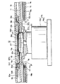
従来、一般に、音声、映像或いはコンピュータのデータ等の情報の記録及び/又は再生が可能なディスク状記録媒体がカートリッジ筐体内に回転自在に収納されたディスク記録媒体装置としては、例えば、図51に示すような構成のものが知られている。このディスク記録媒体装置1は、コンピュータのデータ等の情報を使用者が後から記録(書き込み)できる追記形光磁気ディスク4を内蔵している情報記録メディアである。
【0003】
このディスク記録媒体装置1は、一対の上シェル2a及び下シェル2bによって構成されるカートリッジ筐体2と、このカートリッジ筐体2のディスク収納室3内に回転自在に収納された光磁気ディスク4等を備えている。カートリッジ筐体2の上下両面には、中央部から一辺に向かって延びる上下の開口部5が設けられている。この開口部5は、その一辺に沿ってスライド可能とされたシャッタ部材6によって開閉可能とされている。このシャッタ部材6は、面方向に対向された一対のシャッタ片6aを有しており、図に現れないスプリングによって開口部5を閉じる方向へ常時付勢されている。符号8は、各シャッタ片6aにおける先端部の抜け出しを防止するための押え部材である。
【0004】
また、光磁気ディスク4の中央部には、金属によって円盤状に形成されたセンタハブ7が設けられている。このセンタハブ7は、開口部5の内側端部に対応された位置、即ち、カートリッジ筐体2の略中央部に配置されている。このセンタハブ7には、情報記録再生装置の本体側に設けられるターンテーブルが装着され、そのターンテーブルによるチャッキングにより固定されて光磁気ディスク4が所定速度(例えば、線速度一定)で回転駆動される。この際、開口部5内にヘッド部が挿入される光磁気ピックアップ装置の働きにより、光磁気ディスク4に対する情報信号の記録又は再生が行われる。
【0005】
【発明が解決しようとする課題】
しかしながら、このような構成を有する従来のディスク記録媒体装置においては、上シェル2aと下シェル2bを重ね合わせることによって構成されるカートリッジ筐体2にシャッタ部材6が移動可能に取り付けられており、このシャッタ部材6のシャッタ片6aを開口部5に位置合せすることによって当該開口部5を閉鎖すると共に、シャッタ片6aの周縁部を開口部5の周縁部とオーバーラップさせることによって防塵性を確保し、ディスク収納室3内に塵や埃等が入り込むのを防止するようにしていた。そのため、シャッタ部材6の組立時におけるクリアランスやシャッタ片6aの反り等によって開口部5の周縁部との間に隙間が生じてしまうことがあり、防塵性能が劣化するおそれがあるという課題があった。
【0006】
近年、光ディスクの大容量化、高記録密度化の流れの中、記録パターンの狭ピッチ化、線密度の増大化が進んでいる。そのため、光ディスクや光磁気ディスク等の情報記録面上に塵や埃等が付着した場合には、光学ピックアップ装置による情報の読み取りや書き込みに支障を来すことがあり、正常な情報の読み書きができなくなってしまうことがある。
【0007】
ところが、更なる大容量化、高記録密度化により、従来では影響の少なかった微小な塵や埃等であってもデータの読み書きに対する影響度が高くなり、上述したように、単に上下シェル2a,2bを重ね合わせて組み立てただけでは、微小なサイズの塵や埃等の侵入を防ぐことができなかった。この場合、カートリッジ筐体2内に侵入した微小な塵や埃等が光磁気ディスク4の情報記録面に付着すると、この塵や埃等によって情報記録面が傷つけられた場合と同様の状態となり、正常な情報の読み書きができなくなってしまう。
【0008】
本発明は、このような従来の課題に鑑みてなされたものであり、互いに接合される一対のシャッタ部材のそれぞれの接合部に、略全長に渡って凹凸部を設け、互いに凹凸部を係合させて一対のシャッタ部材を閉じ合わせることにより、上述した課題等を解決することができるディスクカートリッジ、ディスク記録媒体装置及びディスク記録及び/又は再生装置を提供することを目的としている。
【0010】
【課題を解決するための手段】
上述したような課題等を解決し、上記目的を達成するために、本出願のディスクカートリッジは、上シェル、回転部材及び下シェルを重ね合わせることによって上シェル及び回転部材間又は回転部材及び下シェル間にディスク収納室が形成され、回転部材が上シェル及び下シェルの少なくとも一方によって回転自在に支持されると共に、上シェル及び下シェルの少なくとも一方又は上シェル及び下シェルの少なくとも一方と回転部材とに開口部が設けられたカートリッジ筐体と、カートリッジ筐体に設けられ、回転部材の回転に応じて開口部を開く開位置と開口部を閉じる閉位置との間に移動可能とされると共に、閉位置において互いに接合する接合部を有する一対のシャッタ部材と、を備え、一対のシャッタ部材の各々の接合部には、互いに係合可能な凹凸部を接合部の略全長に渡って設けたことを特徴としている。
【0012】
本出願のディスク記録媒体装置は、上シェル、回転部材及び下シェルを重ね合わせることによって上シェル及び回転部材間又は回転部材及び下シェル間にディスク収納室が形成され、回転部材が上シェル及び下シェルの少なくとも一方によって回転自在に支持されると共に、上シェル及び下シェルの少なくとも一方又は上シェル及び下シェルの少なくとも一方と回転部材とに開口部が設けられたカートリッジ筐体と、ディスク収納室内に回転自在に収納されるディスク状記録媒体と、カートリッジ筐体に設けられ、回転部材の回転に応じて開口部を開く開位置と開口部を閉じる閉位置との間に移動可能とされると共に、閉位置において互いに接合する接合部を有する一対のシャッタ部材と、を備え、一対のシャッタ部材の各々の接合部には、互いに係合可能な凹凸部を接合部の略全長に渡って設けたことを特徴としている。
【0013】
また、本出願のディスク記録及び/又は再生装置は、カートリッジ筐体に形成されたディスク収納室内にディスク状記録媒体が回転自在に収納されると共に、ディスク状記録媒体の一部を露出させるためカートリッジ筐体に設けた開口部が一対のシャッタ部材によって開閉自在とされたディスク記録媒体装置と、ディスク記録媒体装置の挿脱動作に応じて一対のシャッタ部材を移動させて開口部を開閉させるシャッタ開閉手段と、ディスク記録媒体装置が着脱可能に装着されると共に、ディスク記録媒体装置の装着時、シャッタ開閉手段で開放された開口部から挿入されてディスク状記録媒体をチャッキングして回転駆動するディスクドライブ装置と、を備えたディスク記録及び/又は再生装置において、カートリッジ筐体は、上シェル、回転部材及び下シェルを重ね合わせることによって構成されると共に、上シェル及び回転部材間若しくは回転部材及び下シェル間にディスク収納室が形成され、回転部材が上シェル及び下シェルの少なくとも一方によって回転自在に支持されると共に、上シェル及び下シェルの少なくとも一方又は上シェル及び下シェルの少なくとも一方と回転部材とに開口部が設けられ、一対のシャッタ部材は、カートリッジ筐体に設けられ、回転部材の回転に応じて開口部を開く開位置と開口部を閉じる閉位置との間に移動可能とされると共に、閉位置において互いに接合する接合部を有し、一対のシャッタ部材の各々の接合部には、互いに係合可能な凹凸部を接合部の略全長に渡って設けたことを特徴としている。
【0014】
上述のように構成したことにより、本出願のディスクカートリッジ、ディスク記録媒体装置及びディスク記録及び/又は再生装置では、一対のシャッタ部材の各々の接合部には、その略全長に渡って凹凸部が設けられているため、開口部を閉じる閉位置においては、互いの凹凸部を係合させて接合部をしっかりと閉じ合わせることができる。その結果、一対のシャッタ部材による開口部の防塵性能を高めることができ、微小なサイズの塵や埃等の侵入を防止又は効果的に抑制し、カートリッジ筐体内に収納されているディスク状記録媒体の情報記録面に塵や埃等が付着するのを防止して、正常な情報の読み書きを確保することができるディスクカートリッジ、ディスク記録媒体装置及びディスク記録及び/又は再生装置を提供することができる。
【0015】
【発明の実施の形態】
以下、本発明の実施の形態を、添付図面を参照して説明する。図1〜図50は、本発明のディスクカートリッジ、ディスク記録媒体装置及びディスク記録及び/又は再生装置の実施の例を示すものである。
【0016】
ここで、本出願において、「ディスクカートリッジ」とは、主要な構成メンバとして上下シェル若しくは上下シェル及び回転部材と、1枚若しくは一対のシャッタ部材(通常は2枚であるが、3枚以上の組み合わせでも良い。)を有し、ディスク状記録媒体を収納する以前の筐体のみからなるものを言うものとする。また、「ディスク記録媒体装置」とは、ディスクカートリッジのディスク収納室内にディスク状記録媒体を収納し、カートリッジ筐体とディスク状記録媒体との組み合わせからなるものを言うものとする。更に、「ディスク記録及び/又は再生装置」とは、ディスク記録媒体装置とテーブル駆動装置と光学ピックアップ装置等の組み合わせからなるものを言うものとする。
【0017】
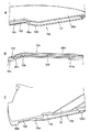
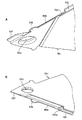
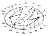
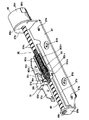
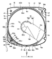
図1はディスク記録媒体装置の第1の実施例を上側から見た分解斜視図、図2は同じく下側から見た分解斜視図、図3は上シェルの斜視図、図4は上シェルの底面図、図5はチャックリング及びリングホルダの斜視図、図6はチャックリング及びリングホルダの中央部で断面した斜視図、図7は回転部材の斜視図、図8は回転部材の平面図、図9は一対のシャッタ部材の分解斜視図、図10は一対のシャッタ部材の組立斜視図、図11は第1のシャッタ部材の平面図、図12は第1のシャッタ部材の斜視図、図13A,B及び図14A,B,Cは第1のシャッタ部材の要部を示す斜視図、図15は第2のシャッタ部材の平面図、図16は第2のシャッタ部材の斜視図、図17A,B及び図18A,B,Cは第2のシャッタ部材の要部を示す斜視図である。
【0018】
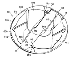
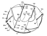
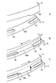
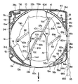
図19は回転部材に一対のシャッタ部材を搭載した状態を示す平面図、図20は図19のZ−Z線部分の断面分解斜視図、図21は図20の回転部材に設けた開口部を一対のシャッタ部材で完全に閉じた状態を示す斜視図、図22は図21から回転部材が略5°回転した状態を示す斜視図、図23は図21から回転部材が略30°回転した状態を示す斜視図、図24は図21から回転部材が略55°回転した状態を示す斜視図、図25は一対のシャッタ部材の他の実施例を回転部材に搭載した状態を示す斜視図、図26A,Bは誤消去防止具及びロック部材の斜視図である。
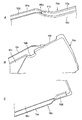
【0019】
図27は下シェルの斜視図、図28は下シェルの平面図、図29はディスク記録媒体装置を上側から見た組立斜視図、図30はディスク記録媒体装置を下シェル側から見たシャッタ閉状態の斜視図、図31は同じくシャッタ開状態の斜視図、図32はディスク記録媒体装置の位置決め穴部分の断面図、図33はディスク記録媒体装置のチャッキング前の状態を示す断面図、図34は同じくチャッキング状態を示す断面図、図35A,B,Cは回転部材の昇降動作を示す説明図、図36は上下シェル、回転部材及びシャッタ部材間の公差を説明するための分解断面図、図37は同じく公差を説明するための組立断面図である。
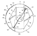
【0020】
図38はディスク記録媒体装置が用いられるテーブル駆動装置の一実施例を示す斜視図、図39は同じく送りねじ動力装置の動力伝達部材等を断面して示す斜視図、図40はテーブル駆動装置の回路構成の一実施例を示すブロック線図、図41はテーブル駆動装置にディスク記録媒体装置を挿入する前の状態を示す斜視図、図42は同じく挿入中の状態を示す斜視図、図43はディスク記録媒体装置のシャッタを開閉するシャッタ開閉手段の一実施例を示す斜視図である。
【0021】
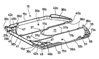
また、図44はディスクカートリッジのシャッタ機構とシャッタ開閉手段との関係を示すシャッタ閉じ状態の説明図、図45は下シェルを取り除きシャッタ部材の全閉状態から回転部材が略5°回転した状態の説明図、図46は同じく全閉状態から回転部材が略30°回転した状態の説明図、図47は同じくシャッタ部材の全開状態(回転部材が略55°回転した状態)の説明図である。更に、図48はディスク記録媒体装置の第2の実施例を下側から見た分解斜視図、図49は第2の実施例に係るディスク記録媒体装置を下シェル側から見たシャッタ閉状態の斜視図、図50は同じくシャッタ開状態の斜視図である。
【0022】
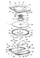
本発明のディスクカートリッジを含むディスク記録媒体装置10は、ディスク状記録媒体として、オーディオ情報としての音楽信号やビデオ情報としての映像信号及び音楽信号等の各種の情報信号が予め記録された再生専用型の光ディスク、或いはオーディオ情報やビデオ情報等の情報信号が1度だけ記録可能(追記型)若しくは何度でも繰り返して記録可能(書換え型)とされた記録可能型の光ディスク11を収納したものである。しかしながら、ディスク状記録媒体としては、これに限定されるものではなく、例えば、薄い円盤の表面に磁性薄膜層を形成して特定位置の磁化状態により情報を記憶するようにした磁気ディスク、同様に形成した磁性薄膜層に光ヘッドと磁気ヘッドを使用して情報を書き込み又は読み出すようにした光磁気ディスクその他のディスク状をなす記憶媒体を適用することができるものである。
【0023】
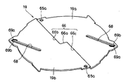
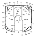
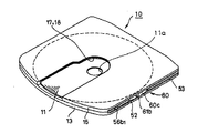
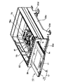
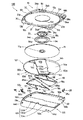
ディスク記録媒体装置10は、図1及び図2に示すように、一対の上シェル13、回転部材14及び下シェル15を重ね合せることによって形成されるカートリッジ筐体12と、このカートリッジ筐体12内に形成されたディスク収納室16内に回転自在に収納される光ディスク11と、回転部材14及び下シェル15に形成された内側開口部18及び外側開口部17を開閉する一対のシャッタ部材19a,19b等を備えて構成されている。このディスク記録媒体装置10から光ディスク11を取り除いたものがディスクカートリッジである。
【0024】
ディスク記録媒体装置10は、通常、光ディスク11を水平状態にして使用されるため、この出願においては、光ディスク11の上側に配されるシェルを上シェル13と言い、光ディスク11の下側に配されるシェルを下シェル15と言うものとする。しかしながら、ディスク記録媒体装置10は光ディスク11を垂直状態或いは斜め状態にして使用することができるものであり、かかる場合には、この実施例で言う上シェル13は第1のシェルと言い換え、下シェル15は第2のシェルと言い換えるものとする。
【0025】
上シェル13は、図1〜図4に示すように、正面側が円弧形状とされた略四角形をなす薄い皿状の部材からなる。この上シェル13の下面(図4において表面として現れている面)の中央部には周方向に連続する環状の上内面壁21が形成されており、この上内面壁21の内側に円形の上凹陥部16aが設定されている。そして、上内面壁21の外側には、周方向に連続して上内面壁21を囲うように環状のカム溝22が設けられている。このカム溝22の周方向の3箇所には、図35A等に示すように、所定長さのカム部22a(図4において格子縞状にハッチングした部分)が略等間隔に設けられている。カム部22aは、回転部材14が回転変位して上シェル13に対して所定位置に移動したときに回転部材14をリフトアップさせて下シェル15に近づけるものである。このカム部22aの作用は、後に詳細に説明する。
【0026】
この上シェル13の外周縁には、上前面縁13aと左右の上側面縁13b,13cと上後面縁13dとが形成されている。上前面縁13aの略中央部には、下シェル15との位置合わせを行うと共に後述する光学ヘッドを出し入れするための第1の凹部23aが設けられている。また、上後面縁13dの中央部は内側に後退されており、その凹陥部13d0には下シェル15の下後面縁が装着される。更に、上後面縁13dの略中央部には、下シェル15との位置合わせを行うための第2の凹部23bが設けられている。そして、上内面壁21の第1及び第2の凹部23a,23bと対向する位置には、各凹部23a,23bに対応された形状及び大きさを有する切欠き21a,21bが設けられている。
【0027】
また、上シェル13の一方の上前面縁13a及び上側面縁13cとカム溝22との間には、それぞれに所定の隙間をあけて2つの前側上囲い壁24a,24bが設けられている。更に、上後面縁13d及び上側面縁13bとカム溝22との間には、それぞれに所定の隙間をあけて2つの後側上囲い壁24c,24dが設けられている。そして、上後面縁13d及び上側面縁13cとカム溝22との間には、同じくそれぞれに所定の隙間をあけて2つの後側上囲い壁24e,24fが設けられている。これら上囲い壁24a〜24fの高さは上内面壁21よりも高く設定されており、特に、各角部に位置する3箇所の上囲い壁24a、24c及び24eは、組立時において下シェル15の内面に当接し得る高さに設定されている。
【0028】
更に、上シェル13の後側上囲い壁24eの内側には、後述する誤消去防止具25がスライド動作可能に装着されるプラグ収納部26の上凹陥部26aが設けられている。この上凹陥部26aは、誤消去防止具25をスライド操作するための開口窓27の上半分を形成する上切欠き27aが設けられた上後面縁13dと、上切欠き27aの内側を囲うように設けられた上収納壁28aとで形成されている。そして、上凹陥部26aには、誤消去防止具25を間欠的に動作させるため2箇所にノッチが形成されたガイド部29が設けられている。更に、上シェル13の4箇所の角部には、下シェル15をネジ止めするためのネジ止め突起30がそれぞれ設けられている。
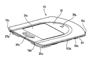
【0029】
図3に示すように、上シェル13の上面は、中央部から背面に掛けて上方へ少々膨出されており、その膨出部31の背面側には、把持する際の滑り止め用の把持凹部31aが設けられている。この膨出部31の前面側には、ディスク記録媒体装置10をテーブル駆動装置に装着する時のカートリッジ挿入方向を示す三角形の指示標識31bが設けられている。そして、指示標識31bと把持凹部31aとの間には、記録内容その他の必要事項を記載することができるラベルを貼付するための上ラベル貼付面31cが設けられている。
【0030】
この上シェル13の内面の中央部には、チャックリング33がリングホルダ34によって回動自在に支持されている。チャックリング33及びリングホルダ34は、図5及び図6に拡大して示すような構成を有している。即ち、チャックリング33は、マグネットによって吸着される磁性材料(例えば、ステンレス鋼SUS430等)によって円板状に形成されている。そして、直径が異なるリング状の凹凸を同心上に複数設けることによってチャックリング33には、最外周に位置するフランジ部33aと、光ディスク11に接触される挟持部33bと、この挟持部33bとフランジ部33aとの間に設定されたテーパ部33cと、最内周に位置する位置規制部33dと、この位置規制部33dと挟持部33bとの間に設定された逃し部33eとが設けられている。
【0031】
チャックリング33の挟持部33bは、光ディスク11のセンタ穴11aを囲う周縁部を押圧してターンテーブルに押しつける押え部の役割を有するもので、この挟持部33bが一面側に突出され、その反対の面側にフランジ部33aが突出されている。そして、フランジ部33aの面と挟持部33bの面の内側に適当な段差をおいて、挟持部33b側からフランジ部33aに向かって逃し部33eと位置規制部33dが設定されている。
【0032】
チャックリング33の位置規制部33dは、図33及び図34に示すように、ターンテーブル81の嵌合部81aの先端部に対向されるもので、その嵌合部81aに内蔵されるマグネット97の磁力を受ける磁力受け部となっている。この位置規制部33dの中央には、嵌合部81aの先端部の形状に対応されてテーパ状の凹陥部33fが設けられており、チャッキング時には嵌合部81aの先端部が着脱自在に嵌合される。
【0033】
また、リングホルダ34は、全体としてリング状に形成されていて、円筒体の一面側に内向きの内フランジ34aが設けられ、他面側に外向きの外フランジ34bが設けられている。リングホルダ34は、チャックリング33を回転自在に収納して支持するもので、外フランジ34bを溶着や接着剤による接着等の固着手段によって上シェル13の内面の略中央部に一体的に固定されている。尚、リングホルダ34の外フランジ34bの表面を上シェル13の内面と同一高さの面とするため、上シェル13には外フランジ34bが嵌合される取付穴13eが設けられている。
【0034】
このリングホルダ34の内フランジ34aの内径はチャックリング33の挟持部33bの外径よりも大きいがフランジ部33aの内径よりは小さく形成されていて、テーパ部33cの斜面に当接する大きさとされている。従って、チャックリング33の半径方向内側に設定された膨出部は、その中途部までリングホルダ34の中央穴34cに挿入される。そして、リングホルダ34の内フランジ34aの内周縁によってチャックリング33のテーパ部33cが下方から支持される。その結果、リングホルダ34内においてチャックリング33は、その面方向へ所定範囲内で移動可能とされていると共に、その面方向と直交する厚み方向(軸方向)へも所定範囲内で移動可能とされている。
【0035】
このようなリングホルダ34の形状に対応させて、上シェル13の内面に設けた取付穴13eには、2つの環状凸部98a,98bが設けられている。2つの環状凸部98a,98bはチャックリング33の中心と同心になるように形成されており、内側に設定された第1の環状凸部98aの内面にはチャックリング33の位置規制部33dの外面が対向され、外側に設定された第2の環状凸部98bの外面にはチャックリング33のテーパ部33cの内面が対向される。これら第1及び第2の環状凸部98a,98bを設けることにより、ディスク記録媒体装置10を縦置きにした状態におけるチャックリング33の傾きを小さくすることができる。
【0036】
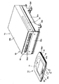
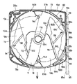
このような上シェル13の下面に下シェル15が重ね合わされる。下シェル15は、図1、図2、図27及び図28に示すように、その外観形状は上シェル13のそれと略同様とされており、正面側が円弧形状とされた略四角形をなす薄い皿状の部材からなる。この下シェル15には、正面側に開口された外側開口部17が設けられている。外側開口部17は、下シェル15の略中央部に設けられたテーブル用開口部17aと、このテーブル用開口部17aに連続して半径方向に延在され且つ前面に開口されるヘッド用開口部17bとからなっている。
【0037】
外側開口部17は、後述するテーブル駆動装置のターンテーブルと、同じく後述する光学ピックアップ装置の光学ヘッドを、ディスク収納室16内に収納される光ディスク11に臨ませるためのもので、これらが自由に出入りできる広さに設定されている。即ち、テーブル用開口部17aにはターンテーブルが出し入れされ、また、ヘッド用開口部17bには光学ヘッドが出し入れされる。更に、下シェル15の四隅には円弧状に連続された下内面壁36a,36b,36c及び36dが形成されており、この内面壁36a〜36dの内側に下凹陥部16bが設定されている。
【0038】
また、下シェル15の外側開口部17の内面側周縁には、シャッタ部材との隙間を小さくして気密性を高めるためのリブ37が設けられている。リブ37は、テーブル用開口部17aの周縁に沿って半円状に形成された円弧状リブ部37aと、ヘッド用開口部17bの両縁に沿って平行に形成された直線状リブ部37b,37bと、この直線状リブ部37bとバランスを取るよう反対方向に延在されて形成された対称リブ部37c,37cを有している。そして、各直線状リブ部37b及び各対称リブ部37cの外側には、各シャッタ部材の19a,19bの外側にできる隙間を塞ぐための遮蔽部38a,38bが設けられている。
【0039】
更に、下シェル15の下凹陥部16b内には、回転部材14の回転運動に基づいて一対のシャッタ部材19a,19bを開閉動作させる一対の操作凸部39a,39bが設けられている。一対の操作凸部39a,39bは、一対のシャッタ部材19a,19bに対応するそれぞれの支点をなすもので、テーブル用開口部17aを挟むように外側開口部35の両側に配置されている。この操作凸部39a,39bを中心として各シャッタ部材19a,19bが、一方において下シェル15に回動自在に支持されている。
【0040】
また、下シェル15の外周縁には、下前面縁15aと左右の下側面縁15b,15cと下後面縁15dとが設けられている。これら下前面縁15a、下側面縁15b,15c及び下後面縁15dは、それぞれ高さ方向中途部に段部を設けて上部の肉厚を薄くした段付き構造とされている。これら下前面縁15a、下側面縁15b,15c及び下後面縁15dの各薄肉部が上シェル13の上前面縁13a、上側面縁13b,13c及び上後面縁13dの内側にそれぞれ入り込み、各段部が上前面縁13a、上側面縁13b,13c及び上後面縁13dの各下端面に当接される。
【0041】
この下シェル15の下前面縁15aの略中央部に開口されたヘッド用開口部17bの開口端40aが上シェル13の第1の凹部23aに係合され、前側の位置決めがなされる。また、下後面縁15dの中央部には、上シェル13の第2の凹部23bに係合される位置決め部40bが設けられており、これにより後側の位置決めがなされる。この位置決め部40bの外側には、外面がラベルの貼付面とされたラベル貼付壁41が設けられている。このラベル貼付壁41は、できるだけ広い平面部分を確保できるように上シェル13側に大きく突出されており、組立時には凹陥部13d0に差し込まれる。
【0042】
下シェル15の一方の下前面縁15a及び下側面縁15cと下内面壁36bとによって前側下囲い壁42aが形成されている。更に、下後面縁15d及び下側面縁15bと下内面壁36cとによって後側下囲い壁42bが形成されている。そして、下後面縁15d及び下側面縁15cと下内面壁36dとによって後側下囲い壁42cが形成されている。これにより、上下シェル13,15の組立時には、前側下囲い壁42aの内側に上シェル13の前側上囲い壁24aが嵌合される。そして、後側下囲い壁42bの内側には後側上囲い壁24cが嵌合され、後側下囲い壁42cの内側には後側上囲い壁24eが嵌合される。
【0043】
更に、下シェル15の後側下囲い壁42cの内側には、誤消去防止具25が装着される下凹陥部26bが設けられている。この下凹陥部26bは、開口窓27の下半分を形成する下切欠き27bが設けられた下後面縁15dと、下切欠き27bの内側を囲うように設けられた下収納壁28bとで形成されている。この下凹陥部26bの下面には、誤消去防止具25をガイドしてスライド方向を規制するガイド溝43が設けられている。この下凹陥部26bと上凹陥部26aとでプラグ収納部26が構成されている。
【0044】
誤消去防止具25は、図26Aに拡大して示すような構成を有している。即ち、誤消去防止具25は、全体として立方体のような形状とされていて、正面部25aには一側に突出された突出部が設けられている。この正面部25aの突出部と反対側には、誤消去防止具25をスライド操作するための操作突起25bが設けられている。更に、誤消去防止具25の下面には、下シェル15のガイド溝43に摺動可能に係合されるガイド突起25cが設けられている。また、正面部25aと反対側の背面には、ガイド部29に係合させて脱落を防止する係合部25dが設けられている。この係合部25dの近傍には、図示しないが、ガイド部29の切欠きに弾性的に係合される弾性片が設けられており、この弾性片の弾性によってスライド操作時のクリック感が付与されている。
【0045】
また、図28に示すように、下シェル15の4箇所の角部には、下シェル15を上シェル13にネジ止めするための前取付穴44a及び後取付穴44bがそれぞれ設けられている。各後取付穴44bは、下シェル15の内面に設けられた円筒状の筒軸部45を貫通しており、各後取付穴44bの内面側には上シェル13のネジ止め突起30が嵌合される。
【0046】
更に、各筒軸部45の近傍には位置決め軸部46a,46bが設けられている。第1の位置決め軸部46aは平面円形の凸部とされている一方、第2の位置決め軸部46bは平面長円形の凸部とされている。そして、各位置決め軸部46a,46bの上端には、上下シェル13,15間の位置合わせを行うための一対の基準突起47,47が設けられている。一対の基準突起47,47は、それぞれ平面形状が円形とされていて、略同一の高さに設定されている。
【0047】
一対の基準突起47,47に対応させて上シェル13には、図32に示すように、一対の基準穴48,48がそれぞれ設けられている。そして、各基準突起47との干渉を避けるため上シェル13の後側上囲い壁24c及び後側上囲い壁24eには、図4に示すように、円形に湾曲された逃げ部49aと長円形に湾曲された逃げ部49bが設けられている。
【0048】
また、下シェル15の各位置決め軸部46a,46bには、基準突起47と反対側の下面に開口する一対の位置決め穴50a,50bが設けられている。これら一対の位置決め穴50a,50bは、ディスク記録媒体装置10をディスク記録再生装置の所定位置であるディスク装着部に位置決めするためのものである。そのため、第1の位置決め穴50aは平面円形とされている一方、第2の位置決め穴50bは,位置決め時における横方向の寸法誤差を吸収するため横長の長円形とされている。
【0049】
このような構成を有する上シェル13と下シェル15を重ね合わせることによって形成される上下の凹陥部16a,16b内に回転部材14が回転自在に収納される。この上下シェル13,15と回転部材14とによってカートリッジ筐体12が構成されている。
【0050】
上下に重ね合わされた上下シェル13,15の一方の側縁部13b,15bの略中央部には、回転部材14の外周面の一部を露出させるための開口窓52が設けられている。この開口窓52は、上シェル13の接合部に設けた上切欠き部52aと、下シェル15の接合部に設けた下切欠き部52bとによって形成されている。更に、上下シェル13,15の一方の側縁部13b,15bには、その接合面に沿って前後方向に延びる装填ガイド溝53が設けられている。装填ガイド溝53は、後述するシャッタ開閉手段の挿入により回転部材14を回動操作するために設けたものである。
【0051】
この装填ガイド溝53に対応するよう他方の側縁部13c,15cには、その接合面に沿って前後方向の中途部まで延びる誤挿入検出溝54が設けられている。装填ガイド溝53及び誤挿入検出溝54は、上シェル13及び下シェル15にそれぞれ半分ずつ設けられており、両シェル13,15を組み合わせることによって四角形の溝がそれぞれ形成されている。この装填ガイド溝53と誤挿入検出溝54との組み合わせにより、ディスク記録媒体装置10をテーブル駆動装置に装着する際の誤挿入を防止して、常に正しい姿勢でディスク記録媒体装置10を装着することができる。
【0052】
更に、上下シェル13,15の一方の前縁部13a,15aの内側にはロック収納部55が設けられている。そして、ロック収納部55には、回転部材14を所定位置でロックするためのロック部材56が揺動可能に支持されている。ロック収納部55は下凹陥部16bに連通されていると共に、一方の側縁部13b,15bに設けられた開口穴57を介して装填ガイド溝53に連通されている。このロック収納部55の一方を形成する下シェル15には、ロック部材56を揺動自在に支持する支持軸58が、上シェル13側へ突出するように設けられている。
【0053】
ロック部材56は、図26Bに拡大して示すように、支持軸58に回動自在に嵌合されて面方向へ揺動可能とされたレバー状の部材によって形成されている。即ち、ロック部材56は、リング状をなす回動軸部56aと、この回動軸部56aから一側に突出する操作アーム56bと、回動軸部56aから他側に突出するロックアーム56c及び弾性アーム56dとによって構成されている。操作アーム56bの先端には側方に突出する入力部56b1が設けられている。また、ロックアーム56cと弾性アーム56dとの間には適当な大きさの隙間が設定されており、ロックアーム56cの先端にはロック爪56c1が設けられ、弾性アーム56dの先端には支持頭部56d1が設けられている。
【0054】
このような構成を有するロック部材56は、図44等に示すような状態で支持軸58に取り付けられる。即ち、ロック爪56c1を下凹陥部16b側に向けた状態で回動軸部56aを支持軸58に嵌合し、弾性アーム56dの支持頭部56d1を下シェル15の下前縁部15aの内面に当接させる。これにより、弾性アーム56dのバネ力によってロックアーム56cが内側に付勢され、その先端のロック爪56c1が下凹陥部16b内に突出される。これと同時に、操作アーム56bの入力部56b1が開口穴57に内側から挿入され、入力部56b1の先端が装填ガイド溝53内に突出される。このようなバネ体であるロック部材56の材質としては、例えば、ポリアセタール(POM)が好適であるが、その他のエンジニアリングプラスチックを適用することができることは勿論のこと、金属製のバネ材を用いることもできる。
【0055】
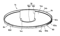
このような上シェル13及び下シェル15の上下凹陥部16a,16b内に回転自在に収納される回転部材14は、図1、図2、図7及び図8に示すような構成を備えている。この回転部材14は、円盤状の薄い板材からなる平面部14aと、この平面部14aの外周縁に連続して設けられたリング部14bを有している。この回転部材14の平面部14aに内側開口部18が形成されている。この内側開口部18は、下シェル15の外側開口部17と形状及び大きさが略等しく形成されている。
【0056】
即ち、内側開口部18も外側開口部17と同様に、平面部14aの中央部に設定され且つターンテーブルが出し入れされるテーブル用開口部18aと、このテーブル用開口部18aに連続され且つ光学ヘッドが出し入れされるヘッド用開口部18bを有している。そして、平面部14aのテーブル用開口部18aの内周縁には、自由状態において光ディスク11の内側非記録領域を下方から支える支持縁部14cが設けられている。
【0057】
また、回転部材14のリング部14bの外周面の一部には、シャッタ開閉手段により係合されてその往復動作により回転部材14を所定の角度範囲内において回動させる被操作部60が設けられている。この被操作部60は、図7及び図8等に示すように、周方向の所定範囲(略30°程度)に渡って多数の歯が設けられたギア部60aと、このギア部60aの一側に連続して設けられた前滑り部60bと、ギア部60aの他側に連続して設けられた後滑り部60cと、ギア部60aから周方向に所定距離離れた位置に設けられたランド部60dを有している。
【0058】
被操作部60の前滑り部60bの外周面はギア部60aの歯先円と略同じ高さに設定され、また、後滑り部60cの外周面はギア部60aの歯底円と略同じ高さに設定されている。そして、前滑り部60bの周方向の略中央部には断面円弧状の切欠きからなる初期動作用凹部61aが設けられ、後滑り部60cの周方向の略中央部には断面台形状の切欠きからなるセット位置用凹部61bが設けられている。
【0059】
この被操作部60のギア部60a及び前後の滑り部60b,60cがリング部14bの外周面から外側へ突出するように設けられているため、上シェル13及び下シェル15の対応する部分には、図4及び図28に示すように、これら突出部との接触を回避してその通過を許容するための上逃げ部52a及び下逃げ部52bが設けられている。この上下逃げ部52a,52bによって開口窓52が構成されている。
【0060】
かくして、下シェル15と回転部材14とロック部材56とは、組立時において、次のような位置関係を有している。図44〜47に示すように、下シェル15の外側開口部17と回転部材14の内側開口部18とが最も大きく回転変位したシャッタ閉じ状態では、被操作部60の前滑り部60bがカートリッジ筐体12の開口窓52に対向され、後滑り部60cの後端縁63bが下シェル15の開口端40aに当接される。このとき、ランド部60dの前滑り部60b側の端面縁63cが下シェル15の位置決め部40bに対向される。また、ロック部材56のロック爪56c1が回転部材14のセット位置用凹部61bに係合され、このロック部材56によって回転部材14がロックされた状態にある。
【0061】
この状態から、ロック部材56によるロックを解除して回転部材14を所定方向に所定角度だけ回動させると、外側開口部17に内側開口部18が合致され、内外開口部17,18が大きく開かれる。その結果、内外開口部17,18を介してディスク収納部16が開口され、光ディスク11の情報記録面の一部が露出される。このとき、前滑り部60bの前端縁63aが下シェル15の位置決め部40bに当接し、これ以上の回転部材14の回動が防止される。また、開口窓52には後滑り部60cのセット位置用凹部61bが対向されると共に、その後端縁63bにロック部材56のロック爪56c1が係合され、これにより回転部材14がロック状態に保持される。
【0062】
また、回転部材14のリング部14bの開口側の端面には、周方向の2箇所に配置された円弧状のカム突起64が設けられている。これらのカム突起64は、回転部材14を上シェル13等に組み立てた状態において、上シェル13のカム溝に係合される。そして、回転部材14が所定角度回転することにより、各カム突起64がカム溝22のカム部22aにそれぞれ乗り上げられ、これにより、回転部材14が下シェル15側に押圧される。
【0063】
この回転部材14の平面部14aには、一対のシャッタ部材19a,19bを当該平面部14aの平面方向へ回動自在に支持するための一対の支持軸14d,14dが設けられている。一対の支持軸14d,14dは、一対のシャッタ部材19a,19bに対応するそれぞれの支点をなすもので、テーブル用開口部18aを中心にして一方がヘッド用開口部18bの縁部分に位置するよう点対称に配設されている。
【0064】
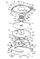
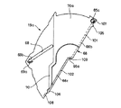
この一対の支持軸14d,14dを介して回転部材14に取り付けられるシャッタ機構19を構成する一対のシャッタ部材19a,19bは、略同一の形状及び大きさとされた2枚のシャッタ部材19a,19bからなっている。一対のシャッタ部材19a,19bは、図9〜図18に示すような形状及び構造を有している。即ち、一対のシャッタ部材19a,19bは、図9及び図10に示すように、略半円形をなす薄い板体によって形成されている。そして、各シャッタ部材19a,19bの弦側辺が、一対のシャッタ部材19a,19bの閉位置において互いに接合する接合部66とされている。
【0065】
図11及び図15に示すように、各シャッタ部材19a,19bの弦側辺の一側部には、それぞれ軸受孔65aが設けられている。各軸受孔65aには、回転部材14に設けた一対の支持軸14dがそれぞれ回動自在に嵌合され、各支持軸14dの先端部をカシメ加工することによって一対のシャッタ部材19a,19bが回転部材14の平面部14a上に載置されて旋回運動自在に取り付けられる。この際、一対のシャッタ部材19a,19bは、互いの弦側を対向させて取り付けるようにする。
【0066】
一対のシャッタ部材19a,19bの接合部66には、互いに係合可能な凹凸部が、その略全長に渡って設けられている。そして、係合部66の弦側辺の中央部には、その弦側辺と直交する方向に延在された段部66aが設けられており、この段部66aによって弦側辺の両側に凸側接合部66bと凹側接合部66cとがそれぞれ形成されている。これにより、各シャッタ部材19a,19bの接合部66において、中央の段部66aから回動中心となる軸受孔65aの近傍まで凸側接合部66bが設定され、これとは反対側の段部66aから先端部の近傍まで凹側接合部66cが設定されている。
【0067】
図11〜図14に示すように、第1のシャッタ部材19aの凸側接合部66bには、その接合面側に開口されると共に、その接合部が延在される長手方向に連続され且つ断面形状がV字状(V溝)をなす長溝部101が設けられている。また、第1のシャッタ部材19aの凹側接合部66cには、その接合面側に突出されると共に、その接合部が延在される長手方向に連続され且つ断面形状が楔状をなす突条部102が設けられている。この長溝部101と突条部102が、接合部66に設けられる凹凸部の一方の第1の具体例を示している。更に、長溝部101と突条部102が連続する部分に段部66aが設けられていて、この段部66aに中央溝部109が設けられている(図11、図12及び図14A,B)。
【0068】
また、図16〜図18に示すように、第2のシャッタ部材19bの凸側接合部66bには、その接合面側に開口されると共に、その接合部が延在される長手方向に連続され且つ断面形状がV字状(V溝)をなす長溝部(凹凸部)103が設けられている。また、第2のシャッタ部材19bの凹側接合部66cには、その接合面側に突出されると共に、その接合部が延在される長手方向に連続され且つ断面形状が楔状をなす突条部(凹凸部)104が設けられている。この長溝部103と突条部104が、接合部66に設けられる凹凸部の他方の第1の具体例を示している。そして、長溝部103と突条部104が連続する部分に段部66aが設けられていて、この段部66aに、中央溝部109に係合される中央突部110が設けられている(図15、図16及び図18A)。
【0069】
図14C、図17A,B及び図20に示すように、それぞれの長溝部101,103及び突条部102,104は、その延在する方向の中途部においてクランク状に折り曲げられた折曲部101a,103a及び102a,104aが設けられている。これらの折曲部101a〜104aは、各シャッタ部材19a,19bの厚みが場所によって異なるため、これに対応するように設けたものである。即ち、各シャッタ部材19a,19bの板厚が厚い部分では問題とならないが、板厚の薄い部分では長溝部101,103及び突条部102,104の幅を適当な厚みに取ることができないことから、これらを所定の厚みに保持するため、これらを一側に変位させることによって折曲部101a〜104aが形成されたものである。
【0070】
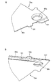
また、一対のシャッタ部材19a,19bの接合部66には、それぞれガイド凸部105とガイド凹部106とが設けられている。ガイド凸部105は、一対のシャッタ部材19a,19bが閉じられるとき、突条部102及び104がそれぞれに対応される長溝部101及び103にスムースに係合できるようにするために設けたもので、軸受孔65aの近傍に設定されている。また、ガイド凹部106は、シャッタ閉位置において、対応するシャッタ部材19a(又は19b)のガイド凸部105を収納するために設けたもので、軸受孔65aと反対側の端部に設定されている。
【0071】
更に又、一対のシャッタ部材19a,19bの接合部66には、それぞれ中心側凸部107と先端側凹部108とが設けられている。中心側凸部107は、接合部66の軸受孔65a側における防塵性を高めるために設けたもので、軸受孔65a側の端部に設定されている。また、先端側凹部108は、シャッタ閉位置において、対応するシャッタ部材19a(又は19b)の中心側凸部107を収納するために設けたもので、軸受孔65aと反対側の端部に設定されている。
【0072】
また、各シャッタ部材19a,19bには、図11及び図15等に示すように、回転部材14の回転動作を介して当該シャッタ部材19a,19bに開口部17,18の開閉運動を与えるための開閉溝68がそれぞれ設けられている。各開閉溝68は、その一端が各シャッタ部材19a,19bの略中央部に設定されており、その一端と軸受孔65aとを結ぶ線の延長線上外側に延在するように形成されている。一対の開閉溝68の外側の端部には、周囲に切り込みを入れることによって形成された弾性片69aと、下シェル15の操作凸部39a,39bを逃がすための凹部69bとが設けられている。この一対の開閉溝68には、下シェル15の一対の操作凸部39a,39bの対応する操作凸部が摺動可能に係合される。
【0073】
更に、一対のシャッタ部材19a,19bには、開口部17,18を完全に閉じた状態において下シェル15のリブ37と対応する形状をなす凹溝からなるリブ逃げ溝70が設けられている。即ち、リブ逃げ溝70は、リブ37の円弧状リブ部37a及び一対の直線状リブ部37b,37bに対応された形状として略U字状に形成されており、その反対側には対称リブ部37c,37cに対応された平面状の逃げ面70aが設けられている。このリブ逃げ溝70とリブ37とにより、図30及び図33に示すように、クランク状をなす迷路のような防塵用隙間71が構成されている。
【0074】
この防塵用隙間71は、迷路のような隙間を設けることによって塵や埃等の侵入を防止することを目的とするものである。この防塵用隙間71は、回転部材14を所定方向に回転して一対のシャッタ部材19a,19bで開口部17,18を完全に閉じることによって形成される。このように、一対のシャッタ部材19a,19bと下シェル15との合わせ面において、クランク状をなす迷路のような隙間を形成することにより、塵や埃等を通り難くしてディスク収納室16内に塵や埃等が侵入するのを防止又は効果的に抑制することができる。
【0075】
かくして、図10に示すように、一対のシャッタ部材19a,19bを組み合わせることにより、互いに凸側接合部66bの端面と凹側接合部66cの端面とがそれぞれ対向され、両者は中央の段部66aによって交差される。そして、互いに対向される凸側接合部66bの長溝部101(及び103)に凹側接合部66cの突条部102(及び104)が係合される。これにより、一対のシャッタ部材19a,19bの接合部66には、閉じ合せ方向に対して凹凸となるクランク状の接触面(或いは隙間)が形成されるため、これにより塵や埃等の通過を抑制することができ、シャッタ接合部における防塵性能を向上させることができる。
【0076】
このような構成を有する一対のシャッタ部材19a,19bは、図19や図21等に示すように、互いの弦側辺を対向させた状態で回転部材14に取り付けられる。従って、一対のシャッタ部材19a,19bをそれぞれ外側へ離反させるように回動させることにより、各シャッタ部材19a,19bは回転部材14の平面部14a上を外側に回動し、これにより内側開口部18が開かれる。一方、一対のシャッタ部材19a,19bをそれぞれ内側へ回動させて対応する凸側接合部66b及び凹側接合部66cをそれぞれ当接させることにより、一対のシャッタ部材19a,19bが略円形となり、その一対のシャッタ部材19a,19bによって内側開口部18の中央部が完全に遮蔽される。
【0077】
尚、この実施例とは逆に、上述したリブ37を一対のシャッタ部材19a,19bに設け、これに対応するリブ逃げ溝70を下シェル15に設ける構成とすることによっても上述した実施例と同様の効果を得ることができる。また、この実施例では、回転部材14の平面部14a側においてその外周縁とシャッタ部材19a,19bとの間には隙間が設定されているが、その隙間を下シェル15に設けた遮蔽部38aによって塞ぐようにしたため、かかる隙間からの塵や埃等の侵入を防止することができる。
【0078】
上述した一対のシャッタ部材19a,19bが、図21に示すように、内側開口部18を開閉できるよう回転部材14に所定の位置関係を持って組み立てられている。そして、一対のシャッタ部材19a,19bを有する回転部材14が、図32及び図44等に示すように、上シェル13及び下シェル15に対して所定の位置関係を持って組み立てられている。
【0079】
即ち、カートリッジ筐体12の組立時、下シェル15の外側開口部17に回転部材14の内側開口部18を対向させるように重ね合わせる。このとき、カートリッジ筐体12の開口窓52には、回転部材14の被操作部60のうち、ギア部60aの一側に連続する前滑り部60bを配置する。これにより、開口窓52の略中央部に初期動作用凹部61aが設置される。この回転部材14と上シェル13とによって円形の空間部からなるディスク収納室16が形成されている。
【0080】
このディスク収納室16内に、ディスク状記録媒体の一具体例を示す光ディスク11が半径方向外側及び厚み方向に所定の隙間を持たせて回転自在に収納されている。このとき、光ディスク11が片面にのみ情報記録面を設けた片面記録方式のものである場合には、その情報記録面を開口部17,18に対向させるように収納する。その結果、光ディスク11の他面であるラベル貼付面が上シェル13側に設定され、ディスク中央のセンタ穴11aにチャックリング33が対向される。
【0081】
光ディスク11は、中央部にセンタ穴11aが設けられた厚みの薄い円板状の記録部材からなる。この光ディスク11のセンタ穴11aには、図33に示すように、ディスク記録再生装置73に内蔵されるテーブル駆動装置のターンテーブル81が嵌合される。このターンテーブル81に内蔵されたマグネット97の磁力によってチャックリング33が吸着され、図34に示すように、チャックリング33とターンテーブル81とで光ディスク11が挟持されて回転方向に一体化される。そして、ターンテーブル81が取り付けられるスピンドルモータ75の駆動により、ターンテーブル81と一体に光ディスク11が所定速度(例えば、線速度一定)で回転される。
【0082】
上述した上シェル13、回転部材14、下シェル15、シャッタ部材19a,19b、誤消去防止具25及びリングホルダ34の材質としては、例えば、ABS樹脂(アクリロニトリル・ブタジエン・スチレン樹脂)やHIPS(高衝撃性ポリスチレン)等の合成樹脂が好適である。しかしながら、その他のエンジニアリングプラスチックを適用できることは勿論のこと、アルミニウム合金、ステンレス鋼その他の金属材料を用いることもできる。また、チャックリング33の材質としては、上述したステンレス鋼に限られるものではなく、鉄その他の磁性体からなる金属は勿論のこと、例えば、プラスチックに磁性材料を含有させて磁性体としたものを適用することもできる。
【0083】
上述したような構成を有するディスク記録媒体装置10は、例えば、次のようにして簡単に組み立てることができる。このディスク記録媒体装置10の組立作業は、上シェル13を下に配置した状態で行われる。まず、上シェル13の上凹陥部16a内に光ディスク11を載置する。このとき、光ディスク11は、情報記録面を下にして上凹陥部16a内に入れ込む。
【0084】
次に、光ディスク11を覆うように回転部材14の開口側を上凹陥部16aに嵌合させる。これにより、回転部材14と上シェル13とで形成されるディスク収納室16内に光ディスク11が回転自在に収納される。このとき、回転部材14の内側開口部18が延在する方向を上シェル13の前後方向に一致させ、被操作部60の前滑り部60bを開口窓52に臨ませる。
【0085】
尚、シャッタ機構19は、予め回転部材14に組み立てておくと良い。その際には、一対のシャッタ部材19a,19bの互いの弦側を対向させ、各軸受穴65aを回転部材14の各支持軸14dに嵌合させて、平面部14a上にそれぞれ載置させる。そして、各支持軸14dの先端部をカシメ加工することにより、一対のシャッタ部材19a,19bが内側開口部18を開閉可能な状態で平面部14aに取り付けられる。
【0086】
次に、ロック収納部55の支持軸58にロック部材56を取り付ける。この際、ロック部材56の弾性アーム56dの支持頭部56d1を上シェル13の上前縁部13aの内面に当接させ、この弾性アーム56dのバネ力によって操作アーム56bの入力部56b1をカートリッジ筐体12の開口穴57から装填ガイド溝53内に突出させる。そして、ロック部材56のロックアーム56cのロック爪56c1を被操作部60のセット位置用凹部61bに係合させる。その結果、回転部材14がロック部材56によってロックされる。
【0087】
これと同時に、又は前後して、誤消去防止具25をプラグ収納部26に装着する。この場合、ガイド突起25c側から挿入し、係合部25dをガイド部29に係合させると共に、操作突起25bを開口窓27の下切欠き27bに係合させる。
【0088】
次に、シャッタ機構19を含む回転部材14の上に下シェル15を被せ、この下シェル15を上シェル13に重ね合わせる。このとき、下シェル15の開口端40aを上シェル13の第1の凹部23aに嵌め合わせると共に、下シェル15の位置決め部40bを上シェル13の第2の凹部23bに嵌め込合わせる。これと同時に、上シェル13の各逃げ部49a,49bに下シェル15の各位置決め軸部46a,46bが嵌合される。そして、各位置決め軸部46a,46bに設けた基準突起47が上シェル13の各基準穴48に嵌合される。これらによって下シェル15が上シェル13に対して自動的に位置決めされる。
【0089】
この際、一対のシャッタ部材19a,19bを図19に示す状態に設定しておくことにより、下シェル15の下凹陥部16b内に設けた一対の操作凸部39a,39bを各シャッタ部材19a,19bに設けた開閉溝68の凹部69bにそれぞれ対向させることができる。そのため、一対の開閉溝68の位置を気に掛けることなく、下シェル15を上シェル13に重ね合わせるだけで一対の操作凸部39a,39bを一対の開閉溝68,68に簡単に係合させることができる。
【0090】
その後、複数本の固定ネジを用いて下シェル15を上シェル13に締め付け固定する。これにより、図29に示すような外観形状と、図32に示すような断面構成を有するディスク記録媒体装置10の組立作業が完了する。この場合、固定ネジ等の別部材からなる固着手段を用いることなく、例えば、接着剤等を用いて上シェル13と下シェル15の接合面を直に接合する構成とすることもできる。このように、本実施例に係るディスク記録媒体装置10によれば、使用される構成部品の点数が比較的少なく、簡単に組立作業を行うことができる。
【0091】
上述したような構成を有するディスク記録媒体装置10によれば、小さい力によって回転部材14を回動させることができ、従って、小さい駆動力によって一対のシャッタ部材19a,19bを開閉動作させることができる一方、外部から入力される衝撃や振動に対しては回転部材14に抵抗力を働かせて一対のシャッタ部材19a,19bを開き難くすることができる。
【0092】
このようなディスク記録媒体装置10は、例えば、図38に示すような構成を備えたディスク記録再生装置73に用いることができる。このディスク記録再生装置73は、テーブル駆動装置78で光ディスク11をチャッキングして回転駆動すると共に、光学ピックアップ装置79で光ディスク11の情報記録面に対してレーザ光を照射して情報信号の読み出し及び書き込みを行うもので、シャーシ74に搭載されている。
【0093】
シャーシ74は砲弾の先端部を切り取ったような平面形状を有しており、その周縁を連続させて上方へ折り曲げることにより補強用リブ74aが設けられている。そして、補強用リブ74aの4個所には、このシャーシ74を図41及び図42に示すような装置本体側の部材に支持するための支持突起74bが設けられている。
【0094】
このシャーシ74の略中央部に、スピンドルモータ75が搭載されたモータベース板76が固定ネジ等の固着手段によって固定されている。シャーシ74のスピンドルモータ75を挟んで長手方向の両側には、ともに四角形とされた第1の開口部77aと第2の開口部77bとが設けられている。そして、第1の開口部77aに関連させてテーブル駆動装置78が取り付けられている。尚、第2の開口部77bは、図示しない別のテーブル駆動装置を取り付けるために使用されるものである。
【0095】
ディスク記録再生装置73は、光ディスク11を所定速度(例えば、線速度一定)で回転駆動するテーブル駆動装置78と、情報信号の書き込み及び読み出しを行うピックアップ装置の一具体例を示す光学ピックアップ装置79と、この光学ピックアップ装置79をテーブル駆動装置78に対して進退動作させるピックアップ移動装置80等を備えている。
【0096】
テーブル駆動装置78は、スピンドルモータ75と、このスピンドルモータ75の回転部に一体に設けられたターンテーブル81等を備えて構成されている。スピンドルモータ75は、薄い板金製のモータベース板76上に取り付けられており、そのモータベース板76の上面にはフレキシブル配線板76aが接着剤等の固着手段によって固定されている。そして、フレキシブル配線板76aの配線回路には、スピンドルモータ75の配線とテーブル駆動用コネクタの配線とが接続されている。更に、コネクタには複数のフレキシブル配線板76bが固定されている。
【0097】
スピンドルモータ75は、図33及び図34に示すように、モータベース板76に固定される固定部75aと、この固定部75aによって回転自在に支持された回転部75bを有し、回転部75bの回転中心となる回転軸にターンテーブル81が一体的に設けられている。ターンテーブル81は、光ディスク11のセンタ穴11aに嵌合される嵌合部81aと、この嵌合部81aの下部に配置されると共にセンタ穴11aの周縁部が載置される載置部81b等を有している。そして、嵌合部81aの内部にマグネット97が内蔵されている。このターンテーブル81に対してチャックリング33が対向され、載置部81b上に載置された光ディスク11を、マグネット97で吸引されるチャックリング33の吸着力で挟持することにより、光ディスク11がチャッキングされてターンテーブル81と一体的に回転可能な状態となる。
【0098】
また、図38に示すように、スピンドルモータ75を両側から挟むように一対のガイド軸82a,82bが、互いに平行となるように配置されている。一対のガイド軸82a,82bは、外周面が平滑とされた丸棒状の部材によって形成されている。そして、第1のガイド軸82aは調整プレート83によって両端支持され、第2のガイド軸82bはシャーシ74によって両端支持されている。
【0099】
調整プレート83は、シャーシ74に対して姿勢変更可能に取り付けられており、この調整プレート83の姿勢を変更することによって一対のガイド軸82a,82b間の平行度が調整可能とされている。この一対のガイド軸82a,82bによって光学ピックアップ装置79が、ターンテーブル81に対して接近及び離反するよう進退移動可能に支持されている。一対のガイド軸82a,82bの一方の端部はスピンドルモータ75の両側に配置され、他方の端部は平行とされてスピンドルモータ75から離れる方向に延在されている。
【0100】
光学ピックアップ装置79は、一対のガイド軸82a,82bにガイドされて摺動するスライド部材84と、このスライド部材84に載置されて往復移動される光学ヘッド等を備えて構成されている。スライド部材84は、一対のガイド軸82a,82bを跨ぐことができる大きさであって、剛性を高くするためにブロック状に形成されている。このスライド部材84の長手方向の一側には、これと交差する幅方向に対をなす軸受部84aが設けられており、これら軸受部84aに第1のガイド軸82aが摺動自在に挿通されている。更に、スライド部材84の長手方向の他側には、第2のガイド軸82bが摺動自在に挿通される図に現れない挿通孔が設けられている。この挿通孔は第2のガイド軸82bの直径よりも大きく形成されており、その隙間の分だけスライド部材84が、第1のガイド軸82aを回動中心として上下方向へ傾動可能とされている。
【0101】
光学ピックアップ装置79の光学ヘッドは、対物レンズ79aを有する2軸アクチュエータと、この2軸アクチュエータを介して情報信号の記録及び再生を行う半導体レーザや光電変換素子等を有する光学制御部等を備えて構成されている。2軸アクチュエータの大部分はヘッドカバー79bによって覆われており、このヘッドカバー79bに設けた開口部から対物レンズ79aが露出されている。この対物レンズ79aが、ターンテーブル81に装着された光ディスク11の情報記録面に対向される。
【0102】
一対のガイド軸82a,82bのうち第1のガイド軸82aは、調整プレート83に設けた一対の軸支持片83a,83aによって支持されている。各軸支持片83aには軸押え板83bが対をなすように設けられており、これらを固定ネジ83cでネジ止めすることによって第1のガイド軸82aが固定支持されている。また、第2のガイド軸82bは、シャーシ74に設けた一対の軸支持片74c,74cに支持されており、それぞれ軸押え板74dにより押えられて、固定ネジ74eでネジ止めすることによって固定支持されている。そして、調整プレート83にはピックアップ移動装置である送りねじ駆動装置98が取り付けられている。
【0103】
送りねじ駆動装置98は、図39に拡大して示すように、送りねじ85と送りモータ86と支持プレート87と動力伝達部材88等を備えて構成されている。送りねじ85は、ガイド軸82a,82bよりも少々短い丸棒の外周面に、螺旋状に延在された1条のねじ溝85aを軸方向の略全長に渡って設けることにより形成されている。この送りねじ85のねじ形状は、溝の両側面に若干の傾斜を持たせた断面形状が台形をなす台形ネジが好適であるが、断面形状が四角形をなす角ネジであってもよく、また、断面形状が半円形をなす半円形ネジとすることもでき、その他の周知形状のねじを適用することができる。
【0104】
送りねじ85は、駆動源である送りモータ86の回転軸を兼ねており、送りモータ86によって直接回転駆動される。送りモータ86は、円筒状のモータケース86aと、このモータケース86aの一方の開口部を閉じるケースカバー86bとを有している。モータケース86aは、支持プレート87のモータ支持片87aにカシメ等の固着手段により固定されて一体的に構成されている。このモータケース86aの内周面には、リング状に巻かれたコイル部が嵌合固定され、その内側にリング状のマグネットが圧入等の固着手段によって嵌合されている。
【0105】
支持プレート87は、送りねじ85と同程度の長さを有する板金製の細長い板材によって形成されている。この支持プレート87の長手方向の両端に、同方向へ立ち上げることにより互いに平行となるように対向されたモータ支持片87aとネジ支持片87bとが設けられている。モータ支持片87aの中央部には貫通孔88aが設けられ、ネジ支持片87bの上部で貫通孔88aと対応する高さ位置には嵌合孔88bが設けられている。このモータ支持片87aの外面に送りモータ86が固定され、送りねじ85が貫通孔88aに貫通されている。そして、送りねじ85の先端部が、嵌合孔88bに嵌合固定される軸受部材によって回動自在に支持されている。
【0106】
また、支持プレート87には、その幅方向の一辺を長手方向に連続させて立ち上げることによりガイド突条87cが設けられている。このガイド突条87cは、送りねじ85の略真下に配置されていると共に、送りねじ85の軸心線と略平行となるように延在されている。更に、支持プレート87には2つの挿通孔87dと、2つの位置決め孔87eとが設けられている。2つの位置決め孔87eによって支持プレート87が所定位置に位置決めされ、挿通孔87dに挿通される取付ネジ89aによって調整プレート83に取り付けられている。
【0107】
動力伝達部材の一具体例を示す送りナット90は、送りねじ85の回転力を直線運動に変換してスライド部材84に伝達するもので、第1のナット部材90a及び第2のナット部材90bと、両ナット部材90a,90bを互いに離反する方向へ付勢するコイルばね90cとから構成されている。
【0108】
第1のナット部材90aはブロック状に形成されたナット本体と、このナット本体の一面側に連続して形成された円筒状の筒軸部とを有し、これらを貫通する軸方向孔の一側に送りねじ85のねじ溝85aに螺合される第1のねじ部90a1が設けられている。更に、第1のナット部材90aには、軸方向と直交する側方へ突出する突出部90a2が設けられている。この突出部90a2には筒軸部が延びる方向に延在されたスリットが設けられており、このスリットに支持プレート87のガイド突条87cが摺動自在に係合されている。
【0109】
また、第2のナット部材90bは、スリーブ状に形成された円筒体からなり、その中心部に軸方向孔が貫通されている。軸方向孔の一側には、送りねじ85のねじ溝85aに螺合される第2のねじ部90b1が設けられている。更に、軸方向孔には第1のナット部材90aの筒軸部が挿脱可能に嵌合される嵌合穴が設けられており、この嵌合穴に半径方向内側に突出したキー状突起が設けられている。この第2のナット部材90bと第1のナット部材90aとの間にコイルばね90cが介在され、そのバネ力で一対のナット部材90a,90bを離反する方向へ付勢することにより、送りナット90と送りねじ85との間に生ずる軸方向のガタを吸収するようにしている。
【0110】
このような構成を有する第1及び第2のナット部材90a,90bとコイルばね90cとが、一体的に組み合わされて送りねじ85に組み立てられている。これらの組立作業は、例えば、次のようなものである。まず、第1のナット部材90aの筒軸部にコイルばね90cを挿入した後、その筒軸部を第2のナット部材90bの筒軸部の嵌合穴に嵌合させる。次に、両ナット部材90a,90bが組み合わされた送りナット90に、送りねじ85を挿通させる。
【0111】
この場合、両ナット部材90a,90bを互いに近づけてコイルばね90cを少々押し縮め、この圧縮状態を保持して送りねじ85を回しながら差し込むようにする。これにより、送りねじ85のねじ溝85aに第1のナット部材90aのねじ部が噛み合わされ、そのねじ溝85aに第2のナット部材90bのねじ部が同時に噛み合わされる。そのため、コイルばね90cのバネ力により、第1のナット部材90aが送りモータ86から離れる方向に付勢され、第2のナット部材90bが送りモータ86に近づく方向に付勢される。
【0112】
その結果、図39において、第1のナット部材90aのねじ部では、図中左側のねじ面が送りねじ85の左側のねじ面に押圧され、右側のねじ面間に隙間が発生する。同様に、第2のナット部材90bのねじ部では、図中右側のねじ面が送りねじ85の右側のねじ面に押圧され、左側のねじ面間に隙間が発生する。これにより、送りナット90全体の隙間を無くすことができ、送りねじ85との間のガタを吸収することができる。そして、第1のナット部材90aの突出部90a2に設けたスリットが支持プレート87のガイド突条87cに係合されているため、送りナット90を送りねじ85の軸方向へ直線的に移動させることができる。
【0113】
更に、第1のナット部材90aには、側方に突出する駆動突起90dが設けられている。この駆動突起90dには、スライド部材84に固定される突起受け部材91が係合されており、この突起受け部材91を介して送りナット90の移動力がスライド部材84に伝達される。突起受け部材91は、スライド部材84に固定するための固定片91aと、この固定片91aに連続された支持片91bと、支持片91bに連続された弾性片91cを有している。
【0114】
固定片91aは細長い板材からなり、その長手方向中途部の幅方向一側にL字状の支持片91bが設けられている。そして、支持片91bの自由端側の先端角部に、駆動突起90dを受けて支持するための切欠きからなる支持部91dが設けられている。弾性片91cは、三角形に折り曲げて2つの角部を設けることによって適度な強さの弾性が付与されており、先端の折曲部を押え部91eとして形成して支持部91dに対向させている。更に、固定片91aには、突起受け部材91をスライド部材84に取り付けるための複数の挿通孔が設けられており、固定ネジ等の固着手段によって取り付けられる。
【0115】
このように取り付けられる突起受け部材91の支持部91dと押え部91eとの間に、送りねじ85に装着されている送りナット90の駆動突起90dが挿入される。そして、弾性片91cのバネ力によって駆動突起90dが支持部91dと押え部91eとで挟持され、これにより、送りナット90とスライド部材84との間に力の伝達が可能となる。
【0116】
調整プレート83及び支持プレート87の材質としては、例えば、ステンレス鋼板が好適であるが、スチール鋼板その他の金属製プレートを用いることができることは勿論のこと、強度の大きなエンジニアリングプラスチックを用いることもできる。また、送りねじ85の材質としては、例えば、ステンレス鋼等のように錆難く、十分に大きな強度を有する金属材料が好適である。更に、突起受け部材91の材質としては、例えば、弾性の大きなステンレス鋼板が好適であるが、その他の板材を用いることもできる。
【0117】
上述した一対のガイド軸82a,82bと調整プレート83と送りねじ駆動装置98とによって光学ピックアップ装置79をターンテーブル81に対して進退動作させるピックアップ移動装置80が構成されている。
【0118】
次に、ディスク記録再生装置73の記録再生装置本体92について説明する。図40は、記録再生装置本体92の一具体例を示すもので、次のような構成要素を備えて構成されている。即ち、記録再生装置本体92は、システムコントローラS1とメモリーコントローラS5とドライブコントローラD1との3つの制御装置を備えている。
【0119】
システムコントローラS1とメモリーコントローラS5とは直に接続されていて、その接続ラインには読取り専用記憶装置(ROM)S2と読取り書込み記憶装置(RAM)S3とが接続されている。更に、メモリーコントローラS5には、メモリーS4とMPEG2(3M〜40Mbps に対応した既存のテレビ放送、HDTV、広帯域ISDNなどに応用される動画圧縮方式)用のエンコーダーS6及びMPEG2用のデコーダーS7とが接続されている。更に、システムコントローラS1には、コントロールパネルS8とリモコン受信部S9が接続されている。
【0120】
また、ドライブコントローラD1には誤り訂正処理回路(ECC)D4が接続されていて、その接続ラインには記憶装置(ROM)D2及び記憶装置(RAM)D3と、サーボ回路D6及びアドレスデコーダーD7が接続されている。更に、ドライブコントローラD1には記録時のエラーを判断する記録時エラー判断回路D8が接続されている。このドライブコントローラD1は、コマンド用インタフェースを介してシステムコントローラS1に接続されている。
【0121】
訂正処理回路D4は、データ用インタフェースを介してメモリーコントローラS5に接続されていると共に、変復調回路D5にも接続されている。そして、変復調回路D5は、光学ピックアップ装置79の対物レンズ79aを有する光学ヘッドに接続されている。更に、サーボ回路D6は、テーブル駆動装置であるスピンドルモータ75と、光学ピックアップ装置79と、記録時エラー判断回路D8とに接続されている。そして、光学ピックアップ装置79はアドレスデコーダーD7に接続され、このアドレスデコーダーD7は記録時エラー判断回路D8にも接続されている。
【0122】
このような構成を有する記録再生装置本体92は、例えば、図41及び図42に示すような中空の筐体からなる外装ケース93に収納されてディスク記録再生装置73の構成要素として使用される。外装ケース93は、上面及び前面に開口されたケース本体93aと、このケース本体93aの上面を閉じるように上部に着脱可能に取り付けられたケース蓋体93bと、ケース本体93a及びケース蓋体93bの前面を閉じるように前部に着脱可能に取り付けられた前面パネル93c等を備えている。この外装ケース93内にディスク記録再生装置73や記録再生装置本体92等が収納されている。
【0123】
外装ケース93のケース本体93aの4箇所には、下方に突出する脚体93dが設けられている。外装ケース93の前面パネル93cは横長とされた板状部材からなり、その上部には横長のカートリッジ出入口94が設けられている。カートリッジ出入口94は、ディスク記録媒体装置10の正面側の大きさと略同程度の大きさに形成されている。このカートリッジ出入口94は、その内側に配置された開閉扉94aによって常時は閉じられている。
【0124】
開閉扉94aは、図示しないスプリングによって閉じ側に付勢されており、図42に示すように、ディスク記録媒体装置10の前部で開閉扉94aを押圧して所定の位置まで差し込むことにより、図示しないローディング機構によってディスク記録媒体装置10が自動的に取り込まれる。そして、ローディング機構で搬送されたディスク記録媒体装置10は、外装ケース93内の所定位置に位置決めされて固定される。これと同時に又は前後して、外装ケース93内に設けられているシャッタ開閉手段によってディスク記録媒体装置10のシャッタ機構19が開放操作され、カートリッジ筐体12の内外開口部17,18が開放される。
【0125】
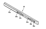
このシャッタ開閉手段の一具体例を示すラック棒95を、図43に示している。このラック棒95は、回転部材14の被操作部60のギア部60aに噛合されるラック部95aと、このラック部95aの先端側に設けられた前弾性片95bと、同じくラック部95aの基端側に設けられた後弾性片95cとを有している。ラック棒95のラック部95aは真っ直ぐな棒材の中途部において一面側に突出するように形成されており、ギア部60aと略同数の歯を有している。
【0126】
ラック棒95の前弾性片95bは、ラック棒95と同方向に延在されて適宜な弾性が付与されており、その先端部に初期動作用凸部96aが設けられている。また、後弾性片95cは、同じくラック棒95と同方向に延在されて適宜な弾性が付与されており、その先端部にストッパ用凸部96bが設けられている。初期動作用凸部96a及びストッパ用凸部96bはラック部95aの歯と同方向に突出されていて、これらは同一直線上に設定されている。
【0127】
更に、初期動作用凸部96aは、断面形状は円弧状とされているが、その大きさ及び高さはラック部95aの歯と略同程度に形成されている。一方、ストッパ用凸部96bは、断面形状はラック部95aの歯と同様に山形とされているが、その大きさ及び高さはやや大きめに形成されている。そして、前後の弾性片95b,95cに適度な大きさの弾性を付与することにより初期動作用凸部96a及びストッパ用凸部96bに対して後退動作が弾性的に行われるようにしている。図43において、符号95dは、ラック棒95の補強を兼ねたガイド部である。このガイド部95dは、ディスク記録媒体装置10の装填ガイド溝53に係合される。
【0128】
このような構成を有するラック棒95の作用によるディスク記録媒体装置10の回転部材14の回動及びシャッタ機構19の開閉動作その他の動作を、図41及び図42、図44〜図47を参照して説明する。
【0129】
図41に示すように、外装ケース93のカートリッジ出入口94に挿入する前のディスク記録媒体装置10の内外開口部17,18は、シャッタ機構19によって完全に閉じられている。この状態から、図42に示すように、ディスク記録媒体装置10を外装ケース93のカートリッジ出入口94からディスク記録再生装置73内に挿入することにより、外装ケース93内に設置されているラック棒95によってロック部材56のロック状態が解除される。その後、ラック棒95の作用によって一対のシャッタ部材19a,19bが開放され、内外開口部17,18が開かれて光ディスク11の情報記録面の一部が露出される。
【0130】
まず、図42及び図44に示すように、ディスク記録媒体装置10を外装ケース93のカートリッジ出入口94に所定量挿入すると、ラック棒95の初期動作用凸部96aが、ディスク記録媒体装置10の一方の側面部に設けた装填ガイド溝53内に入り込む。これにより、初期動作用凸部96aが装填ガイド溝53内に突出されているロック部材56の入力部56b1を、弾性アーム56dの付勢力に抗してロック収納部55内に押し込める。そのため、ロック部材56が支持軸58を中心に回動してロック爪56c1がセット位置用凹部61bから抜け出す。その結果、回転部材14のロックが解除され、その回動が自由となる。
【0131】
次に、図45に示すように、カートリッジ挿入方向Fにディスク記録媒体装置10を挿入し、ラック棒95に対してディスク記録媒体装置10が相対的に前進することにより、初期動作用凸部96aが回転部材14の被操作部60の前滑り部60bに当接し、この前滑り部60bに乗り上げる。このとき、前弾性片95bが適当な強さの弾性を有するため、前弾性片95bの撓みによって初期動作用凸部96aが後方に撓み移動し、前滑り部60bに乗り上げる。その結果、初期動作用凸部96aが被操作部60の初期動作用凹部61a内に入り込む。
【0132】
この凸部96aが凹部61aに係合することにより、ラック棒95からの反力によって回転部材14が、同図において反時計方向に回動される。その結果、ラック棒95との間の相対的な移動量に応じて回転部材14が所定角度回転することにより、凸部96aが凹部61aから離れる前にラック部95aが被操作部60のギア部60aに噛み合う。これにより、動力伝達経路が強固になり、ラック棒95の移動力が確実に伝達され、回転部材14が所定角度回転する。
【0133】
そして、図46に示すように、直線的に前進するラック部95aと曲線的に前進するギア部60aとの噛み合いが解除される前に、ストッパ用凸部96bが被操作部60の後滑り部60cに設けたセット位置用凹部61bに係合される。その後、図47に示すように、ストッパ用凸部96bがセット位置用凹部61bにしっかりと噛み合ったところで、ラック部95aとギア部60aとの噛み合いが解除される。これにより、ディスク記録媒体装置10の挿入動作が終了し、ディスク記録媒体装置10がディスク記録再生装置73の所定位置であるカートリッジ装着部にセットされる。
【0134】
この場合、上述したようにディスク記録媒体装置10のカートリッジ筐体12は、上シェル13の一対の基準穴48,48と下シェル15の一対の基準突起47,47とによって精度良く位置決めされており、これらの基準突起47等と略同軸をなすように一対の位置決め穴50a,50bが下シェル15に設けられている。そのため、ディスク記録媒体装置10をディスク記録再生装置73のディスク装着部に装着することにより、ディスク記録再生装置73に対する下シェル15の位置決め精度がそのまま上シェル13の位置決め精度となるため、上シェル13の位置決め精度を高くすることができる。
【0135】
また、ディスク記録媒体装置10のセット状態では、ストッパ用凸部96bがセット位置用凹部61bにしっかりと噛み合っているため、回転部材14が回動するおそれがない。このとき、回転部材14が回動を開始する初期状態では、図35C及び図37に示すように、回転部材14のリング部14bの端面に設けた複数のカム突起64が上シェル13のカム溝22に設けたカム部22aに乗り上げる。
【0136】
そのため、回転部材14の平面部14aが下シェル15側に移動し、その平面部14aと下シェル15との間で一対のシャッタ部材19a,19bが挟持された状態となる。これにより、回転部材14と下シェル15との間に摩擦力が発生し、回転部材14を回転操作するために必要とされる力が大きくなる。このカム部22aの乗り上げによる摩擦力に抗して回転部材14を回転させることにより、図35Bに示すように、カム突起64がカム部22aを通過する。その結果、カム突起64の摺動による摩擦力が消滅するため、これ以後の回転部材14の回転動作は、極めて軽く且つスムースに行うことができようになる。
【0137】
また、一対のシャッタ部材19a,19bが、回転部材14の回動によって支持軸14dを中心にそれぞれ回動される。これと同時に、各シャッタ部材19a,19bに設けた開閉溝68には下シェル15の操作凸部39a,39bがそれぞれ摺動可能に係合されている。そのため、回転部材14が回動すると、一対の操作凸部39a,39bに対して各開閉溝68が相対的に回動される。その結果、回転部材14の回動量に応じて一対のシャッタ部材19a,19bが、互いに近づく方向である内側(回転部材14の中心側)に移動する。
【0138】
これにより、一対のシャッタ部材19a,19bが、図44(図30を参照)の状態から、図45(同じく図22)及び図46(同じく図23)の状態を経て図47(同じく図24)に示す状態へと変化し、内外開口部17,18を開いて左右に対向する位置に移動する。これにより、回転部材14の内側開口部18と下シェル15の外側開口部17とが完全に開放される。そのため、ディスク収納室16内に収納されている光ディスク11の一部が内外開口部17,18から露出される(図31を参照)。
【0139】
その結果、ディスク記録媒体装置10が図30から図31の状態に変化して、内外側開口部17,18に対するターンテーブル81及び対物レンズ79aを有する光学ヘッドの挿入が可能となる。そこで、ターンテーブル81等をディスク記録媒体装置10側へ移動するか又はディスク記録媒体装置10をターンテーブル81側へ移動することにより、図33から図34の状態に変化して、ターンテーブル81がカートリッジ筐体12中央部のテーブル用開口部17a,18a内に入り込み、光学ヘッドがヘッド用開口部17b,18b内に入り込む。
【0140】
これにより、ターンテーブル81の嵌合部81aが光ディスク11のセンタ穴11aに嵌合され、センタ穴11aの周縁部が載置部81bに載置される。これと同時に、嵌合部81aに内蔵されているマグネット97の磁力が上シェル13のリングホルダ34に保持されているチャックリング33の磁力受け部である位置規制部33dに作用し、その磁力によってチャックリング33が吸引される。その結果、マグネット97の磁力によってチャックリング33の挟持部33bが光ディスク11のセンタ穴11aの周縁部に押しつけられ、その周縁部が挟持部33bとターンテーブル81の載置部81aとで挟持される。
【0141】
これにより、チャックリング33によって光ディスク11がターンテーブル81にチャッキングされ、光ディスク11がターンテーブル81と回転方向に一体化される。このとき、ターンテーブル81の載置部81aの先端部がチャックリング33の位置規制部33dの凹陥部33fに嵌まり込むことによってターンテーブル81に対するチャックリング33の位置合わせが同時に行われ、チャックリング33がターンテーブル81の略中央部に位置決めされる。
【0142】
その結果、チャックリング33が上シェル13から浮き上がった状態となり、チャックリング33のテーパ部33cの内面と上シェル13の第2の環状凸部98bの外側斜面との間、及びテーパ部33cの外面とリングホルダ34の内フランジ34aの内周縁との間、並びにチャックリング33の位置規制部33dの面と上シェル13の第1の環状凸部98aの内側斜面との間にはそれぞれ所定の隙間が保持され、これらが互いに擦れ合うことがない。
【0143】
これと共に、光学ピックアップ装置79の光学ヘッドが開口部17,18内に入り込み、その対物レンズ79aが所定の間隔を保持して光ディスク11の情報記録面に対面される。これにより、ディスク記録再生装置73による光ディスク11の情報記録面に対する情報信号の再生又は記録の動作が可能となる。
【0144】
そこで、テーブル駆動装置本体78を動作させ、スピンドルモータ75の駆動によりターンテーブル81を介して光ディスク11を回転させると共に、光学ピックアップ装置79を駆動させ、光学ヘッドの対物レンズ79aから光ディスク11の情報記録面に向けてレーザ光を照射する。これにより、光ディスク11の情報記録面に予め記録されている情報信号を読み出し、又はその情報記録面に対して新たな情報信号を書き込むことができる。このようにして、ディスク記録再生装置73による情報信号の再生又は記録が実行される。
【0145】
次に、ディスク記録媒体装置10を外装ケース93から排出する場合について説明する。情報信号の再生又は記録の後、例えば、外装ケース93に設けられるカートリッジ排出ボタン(図示せず)を操作することにより、ローディング機構の作動を介してディスク記録媒体装置10がディスク記録再生装置73から離脱され、外装ケース93から排出される。
【0146】
例えば、ディスク装着部にディスク記録媒体装置10を固定した状態において、スピンドルモータ75を後退動作させ、ターンテーブル81をディスク記録媒体装置10の開口部17,18から引き出す。このとき、スピンドルモータ75を後退動作させると、当初はターンテーブル81と光ディスク11とチャックリング33が一体的に移動し、少々移動したところで、チャックリング33のテーパ部33cが上シェル13に固定されているリングホルダ34の内フランジ34aの内周縁に当接する。
【0147】
さらにスピンドルモータ75を後退動作させ、その移動力がマグネット97の吸引力より大きくなることにより、リングホルダ34の抵抗力によってチャックリング33が引き剥がされる。その結果、チャックリング33がリングホルダ34によって上シェル13に保持される。次に、光ディスク11のセンタ穴11aの周縁部が回転部材14の支持縁部14cに当接され、スピンドルモータ75の更なる後退動作によってターンテーブル81の嵌合部81aが光ディスク11のセンタ穴11aから抜き出す。その結果、光ディスク11がカートリッジ筐体12のディスク収納室16内に保持される。そして、開口部17,18からターンテーブル81が完全に抜け出すまで、スピンドルモータ75の後退動作が続けられる。
【0148】
その後、ローディング機構の排出動作によってディスク記録媒体装置10が排出方向に移動すると、相対的にラック棒95が後退動作される。このラック棒95に対するディスク記録媒体装置10の後退動作により、セット位置用凹部61bに係合されているストッパ用凸部96bによって回転部材14が回動される。そして、凸部96bが凹部61bから離れる前にラック部95aがギア部60aに噛合し、この噛み合いによって回転部材14が引き続き回動される。
【0149】
このとき、凸部96bの先端がカートリッジ筐体12の開口窓52内に入り込んでいるため、その凸部96bが開口窓52の縁に当接するが、その凸部96bと一体の後弾性片95cが適度な強さの弾性を有するため、この後弾性片95cの撓み変形によって凸部96bが外側へ弾性変位し、開口窓52の縁を乗り越える。そのため、凸部96bの高さがラック部95aの歯の高さより高いにも係わらず、凹部61bから離れた凸部96bが開口窓52から容易に抜け出すことができ、従って、その後の回転部材14の回動を確保することができる。
【0150】
この回転部材14の回動により、開口窓52内においてラック部95aがギア部60aから離れる前に、初期動作用凸部96aが初期動作用凹部61aに係合される。この凸部96aと凹部61aとの係合によって回転部材14の回動が継続され、回転部材14が最初の位置まで回動される。これにより、被操作部60の後滑り部60cの端面が下シェル15の位置決め部40bに当接されるため、以後の回転部材14の回動が阻止される。
【0151】
これに対して、ディスク記録媒体装置10とラック棒95との間には相対移動が引き続き生じているため、凹部61aに係合されている凸部96aの移動力によって回転部材14には回転力が付与される。この回転力の反力が凸部96aに付与され、この反力を受けて前弾性片95bが撓み変形し、凸部96aが外側へ移動して凹部61aとの係合が解除される。
【0152】
その後、ラック棒95の初期動作用凸部96aが開口穴52を通過することにより、ロック部材56の入力部56b1が開口穴57から装填ガイド溝53内に突出される。これと同時に、ロック部材56のロック爪56c1が内側に移動して回転部材14の被操作部60のセット位置用凹部61bに噛み合わされる。その結果、ロック部材56によって回転部材14がロックされ、その回動が停止される。
【0153】
この際、一対のシャッタ部材19a,19bは、上述した挿入時とは逆の動作を実行し、内外側開口部17,18を完全に閉じる。また、回転部材14のカム突起64はカム溝22内にあるため、回転部材14を軽い力で回転させることができる。更に、カム突起64がカム部22aに当接して乗り上げることにより、これ以後、回転部材14の回動には上述した摩擦力が加えられる。そして、シャッタ機構19が閉じる直前において、操作凸部39b(又は39a)が開閉溝68を最外側部まで移動し、弾性片69aに接触してこれを押圧する。これにより、操作凸部39b(又は39a)の押圧力によって弾性片69aにバネ力が発生する。
【0154】
この弾性片69aのバネ力によって接合部66中央の段部66aには、他方のシャッタ部材19a(又は19b)に作用する圧接力が発生する。この圧接力は、一対のシャッタ部材19a,19bの両者に発生するため、互いの圧接力によって一対のシャッタ部材19a,19bの接合部66が圧接され、密閉性が更に高められる。
【0155】
特に、本実施例においては、一方のシャッタ部材に設けた長溝部101(又は103)に他方のシャッタ部材に設けた突条部102(又は104)を係合させるように互いの接合部に凹凸部を設ける構成としたため、接合部66において、閉じ合わせる方向に対してクランク状の接触面(或いは隙間)が設定されることから、塵や埃等の通過を防止又は抑制することができ、防塵性能を大幅に向上させることができる。従って、一対のシャッタ部材19a,19bの接合部66における防塵性が向上されるため、外部の塵や埃等がディスク収納室16内に侵入するのをより効果的に防止することができる。
【0156】
更に、シャッタ閉じ状態では、長溝部101(又は103)に突条部102(又は104)が係合されることから、接合部66にズレを生ずることがない。そのため、外力がシャッタ部材19a,19bに加えられたような場合においても、一対のシャッタ部材19a,19bに反りが生ずるのを防止又は抑制することができ、防塵性を確保することができる。
【0157】
また、上記実施例においては、一対のシャッタ部材19a,19bの各接合部66は互いに平行に移動するようになっているが、各シャッタ部材19a,19bにガイド凸部105を設けて閉じ合せ方向にオーバーラップ部を設定した。そのため、ガイド凸部105によって各シャッタ部材19a,19bの移動を規制することができ、各シャッタ部材19a,19bの閉じ合せ方向と交差する方向への移動量を制限して閉じ合せ動作の信頼性を高めることができる。
【0158】
このようにして、一対のシャッタ部材19a,19bによって開口部17,18の全体が完全に閉じられ(図30を参照)、その閉じ状態でディスク記録媒体装置10が外装ケース93のカートリッジ出入口94からケース外に排出される。これにより、ディスク記録媒体装置10の排出動作が完了する。
【0159】
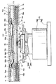
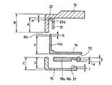
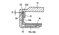
このようなディスク記録媒体装置10において、上シェル13、回転部材14、下シェル15及びシャッタ部材19a,19b間の厚み方向の寸法は、図36及び図37並びに▲1▼式に示すような関係となるように設定することが好ましい。図36に示す符号A〜K及び図37に示す符号Σの意味は、次の通りである。
【0160】
(1) A:上シェル13の上前面縁13a等の端面からカム溝22の面までの高さ
A=2.9mm +0.1/0mm
(2) B:上シェル13の上前面縁13a等の端面から上面までの高さ
B=3.85mm ±0.05mm(参考寸法)
(3) C:下シェル15の下前面縁15a等の端面から下面までの高さ
C=4.15mm +0.1/−0mm(参考寸法)
(4) D:下シェル15の下前面縁15a等の端面から底面までの高さ
D=3.3mm ±0.05mm
(5) E:シャッタ部材19a,19bの厚み
E=1.1mm +0/−0.05mm
【0161】
(6) F:回転部材14の下面から端面までの高さ
F=4.7mm +0/−0.1mm
(7) G:回転部材14のカム突起64の高さ
G=0.2mm +0/−0.05mm
(8) H:上シェル13のカム部22aの高さ
H=0.2mm +0/−0.05mm
(9) J:下シェル15のリブ37の高さ
J=0.2mm +0/−0.05mm(参考寸法)
(10)K:シャッタ部材19a,19bのリブ逃げ溝70の深さ
K=0.2mm +0.05/−0mm(参考寸法)
【0162】
(11)Σ:組立時におけるカム部22aとカム突起64との間の理想的なクリアランス
Σ=−H+A+D−E−F−G ……▲1▼
=0mm +0.45/−0mm(累積公差)
0.064mm +0.322/−0mm(自乗平均×1.66)
【0163】
この計算式▲1▼から明らかなように、理想的なクリアランスΣは、0mm〜0.45mmとすることが好ましく、最も好ましい値は0.2mm位である。
本実施例では、シャッタ開閉動作を行うために回動する回転部材14は、上シェル13と下シェル15の間で0.4mm程度(公差のセンター値)のクリアランスの中で動作し、保存時には0.2mm程度にクリアランスが狭められる。このように、回転部材14を上シェル13に圧着させることなく、0mm〜0.45mm(最適値は0.2mm位)のクリアランスを設定することにより、ゴミの侵入経路を可能な限り狭めて、ディスク収納室16内にゴミが入り込むのを効果的に防止することができる。
【0164】
また、本実施例においては、下シェル15の外側開口部17の周縁部にリブ37(円弧状リブ部37aと直線状リブ部37b)を設けると共に、シャッタ閉じ状態においてリブ37と対応する一対のシャッタ部材19a,19bの対応する部分にリブ逃げ溝70を設け、リブ37とリブ逃げ溝70で防塵用隙間71を構成するようにしたため、開口部17,18がシャッタ部材19a,19bで完全に閉じられたディスク記録媒体装置10の保存時における防塵性能を高めることができ、ディスク収納室16内に塵や埃等が入り込むのを効果的に防止することができる。
【0165】
尚、一対のシャッタ部材19a,19bの接合部66に設ける凹凸部については、上述した実施例では、長溝部と突条部との組み合わせによって構成したが、本発明はこれに限定されるものではなく、例えば、各シャッタ部材19a,19bの接合部66にV字状の長溝部をそれぞれ設け、長溝部同士を嵌合させる構成とすることもできる。この両側の接合部にV字溝を設ける場合には、片側にのみV字溝を設ける場合に比べて、その接触面(又は隙間)の長さを長くできるために、その長さの増加分だけ閉じ合せ方向の深さを浅くすることができる。その結果、シャッタ開放時における一対のシャッタ部材のカートリッジ筐体内に収納される面積を小さくすることができ、従って、ディスクカートリッジ全体の小型化を図ることができる。
【0166】
また、カートリッジ筐体は、回転部材を廃止して上下シェルの組み合わせによって構成することができる。そして、従来例として示す図51のように、直線的に移動して開口部を開閉するシャッタ部材を設ける構成としても良い。かかる構成のカートリッジ筐体に対して、上述した実施例のチャックリング33及びリングホルダ34を設けることによっても、上述した実施例と同様の効果を得ることができる。更に、開口部は、上シェル又は下シェルの一方にのみ設ける構成としてもよく、かかる場合にチャックリングは、開口部の無いシェルに設けるようにする。
【0167】
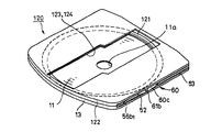
図25は、上述した一対のシャッタ部材19a,19bの他の実施例、特に、ガイド凸部105及びガイド凹部106の他の実施例を示すものである。この第2の実施例に示す一対のシャッタ部材19A,19Bが第1の実施例に示す一対のシャッタ部材19a,19bと異なるところはガイド凸部111及びガイド凹部112のみであり、他の構成は同様であるため、それらの説明は省略する。
【0168】
一対のシャッタ部材19A,19Bのガイド凸部111及びガイド凹部112は、一対のシャッタ部材19a,19bのガイド凸部105及びガイド凹部106と同一位置に設定されていて、その形状のみが異なる点である。ガイド凸部111は、山型に突出する突起とされており、これに対応する山型の凹みとしてガイド凹部112が形成されている。かかる形状のガイド凸部111及びガイド凹部112を設ける場合には、その凸部(角部)が1箇所となるため、閉じ合せ動作における信頼性をより高くすることができる。
【0169】
また、図48乃至図50には、本発明のディスクカートリッジ及びディスク記録媒体装置の第2の実施例を示す。この第2の実施例に示すディスク記録媒体装置120は、2組の光学ピックアップ装置を備えたディスク記録再生装置に使用できるようにした2ヘッドタイプのものである。
【0170】
このディスク記録媒体装置120は、図48〜図50から明らかなように、図2、図30及び図31に示した第1の実施例に係るディスク記録媒体装置10と異なるところは、回転部材14の内側開口部18及び下シェル15の外側開口部17の形状のみであり、その他の形状及び構成は同一である。そのため、図48〜図50において、上述した図2、図30及び図31と同一部分には同一符号を付してその説明を省略し、構成の異なる回転部材121の開口部123及び下シェル122の開口部124について説明する。
【0171】
回転部材121の内側開口部123は、上述した回転部材14の内側開口部18に、一方のヘッド用開口部に対向する他方のヘッド用開口部を直線的に延在させて設けたものである。即ち、内側開口部123は、中央部に設けられた円形のテーブル用開口部123aと、このテーブル用開口部123aを通って直径方向に延びるヘッド用開口部123b,123cとから構成されている。
【0172】
また、下シェル122の外側開口部124も内側開口部123と同様に、上述した下シェル15の外側開口部17に、一方のヘッド用開口部に対向する他方のヘッド用開口部を直線的に延在させて設けている。即ち、外側開口部124は、中央部に設けられた円形のテーブル用開口部124aと、このテーブル用開口部124aを通って前側に延在されて前端縁及び後端縁まで達する略長方形をなすヘッド用開口部124b,124cとから構成されている。
【0173】
このように、2ヘッド用の回転部材121及び下シェル122を1ヘッド用の回転部材14及び下シェル15に代えて使用することにより、一度に2個の光学ヘッドの使用が可能となる。その結果、例えば、一方の光学ヘッドによって新たな情報信号を記録しながら、他方の光学ヘッドによって記録されたばかりの情報信号の記録状態の確認作業を行うことができる。しかも、回転部材121及び下シェル122を1ヘッド用のものと交換するだけで、ディスクカートリッジ及びディスク記録媒体装置の製造を1ヘッド用と2ヘッド用に簡単に対応することができ、製造組立ラインの共通化が可能であって、需要者のニーズに適切に対応することができる。
【0174】
尚、回転部材121及び下シェル122に設けた光学ヘッド2個分の開口部123,124は、互いに直角に配置してL字状としても良く、また、直角以外の適当な角度に交差させて配置する構成とすることができる。更に、下シェル122のみならず、上シェルにも開口部を設け、上下から同時に光学ヘッドを対向させることができる構成とすることもできる。
【0175】
以上説明したが、本発明は上述した実施の例に限定されるものではなく、例えば、上記実施例においては、情報記録媒体として光ディスクを用いた例について説明したが、光磁気ディスク、フレキシブルディスク等の磁気ディスク、その他各種のディスク状記録媒体に適用することができる。更に、上記実施例では、ディスク記録及び/又は再生装置として記録及び再生の両者が可能であるディスク記録再生装置に適用した例について説明したが、記録又は再生の一方のみが可能なディスク記録装置又はディスク再生装置に適用できることは勿論である。
【0176】
また、上記実施例においては、カートリッジ筐体12の下シェル15及び回転部材14に開口部17,18を設けた例について説明したが、例えば、上シェル13にも開口部を設け、カートリッジ筐体12の上下から同時にアクセスできる構造とすることもできる。更に、回転部材14と下シェル15とでディスク収納室を形成し、このディスク収納室内にディスク状記録媒体11を収納すると共に上シェル13に開口部を設ける構成とすることもできる。この場合、上述したチャックリング33は、下シェルに設けるようにする。
【0177】
更に又、上述した実施例では、一対のシャッタ部材19a,19bを回動させて互いの接合部66を平行に移動させることにより開口部17,18を開閉させる例について説明したが、これに限定されるものではなく、例えば、一対のシャッタ部材19a,19bを当初から平行に移動させて開口部17,18を開閉させる構成とすることもできる。
【0178】
また、上記実施例では、シャッタ開閉にあたっては、シャッタ開閉手段を固定してディスク記録媒体装置を移動させることにより開口部を開閉させる例について述べたが、これに限定されるものではなく、シャッタ開閉手段とディスクカートリッジを相対的に移動させてシャッタ部材を開閉動作させる構成であれば良い。例えば、ディスク記録媒体装置をディスク装着部に固定した後、シャッタ開閉手段をモータ等で移動させて開閉動作させるようにしても良い。このように、本発明は、その趣旨を逸脱しない範囲で種々変更できるものである。
【0179】
【発明の効果】
以上説明したように、本出願のディスクカートリッジによれば、ディスク収納室を有するカートリッジ筐体(上シェルと回転部材と下シェルとの組み合わせ)と開口部を開閉する一対のシャッタ部材とを備えたディスクカートリッジにおいて、一対のシャッタ部材の各々の接合部に、その略全長に渡って凹凸部を設ける構成としたため、開口部を閉じる閉位置において互いの凹凸部を係合させ、一対のシャッタ部材の接合部をしっかりと閉じ合わせることができる。その結果、一対のシャッタ部材による開口部の防塵性能を高めることができ、微小なサイズの塵や埃等の侵入を防止又は効果的に抑制することができる。従って、カートリッジ筐体内に収納されているディスク状記録媒体の情報記録面に塵や埃等が付着するのを防止できるディスクカートリッジを提供することができるという効果が得られる。
【0180】
本出願のディスク記録媒体装置によれば、ディスク収納室を有するカートリッジ筐体とディスク状記録媒体と開口部を開閉する一対のシャッタ部材とを備えたディスク記録媒体装置において、一対のシャッタ部材の各々の接合部に、その略全長に渡って凹凸部を設ける構成としたため、開口部を閉じる閉位置において互いの凹凸部を係合させ、一対のシャッタ部材の接合部をしっかりと閉じ合わせることができる。その結果、一対のシャッタ部材による開口部の防塵性能を高めることができ、微小なサイズの塵や埃等の侵入を防止又は効果的に抑制することができる。従って、カートリッジ筐体内に収納されているディスク状記録媒体の情報記録面に塵や埃等が付着するのを防止できるディスク記録媒体装置を提供することができるという効果が得られる。
【0181】
本出願のディスク記録及び/又は再生装置によれば、ディスク状記録媒体が収納されるディスク収納室及びディスク状記録媒体の一部を露出させる開口部を開閉する一対のシャッタ部材を有するディスク記録媒体装置と、一対のシャッタ部材を開閉動作させるシャッタ開閉手段と、ディスク状記録媒体をチャッキングして回転駆動するディスクドライブ装置とを備えたディスク記録及び/又は再生装置において、一対のシャッタ部材の各々の接合部に、その略全長に渡って凹凸部を設ける構成としたため、開口部を閉じる閉位置において互いの凹凸部を係合させ、一対のシャッタ部材の接合部をしっかりと閉じ合わせることができる。その結果、一対のシャッタ部材による開口部の防塵性能を高めることができ、微小なサイズの塵や埃等の侵入を防止又は効果的に抑制することができると共に、カートリッジ筐体内に収納されているディスク状記録媒体の情報記録面に塵や埃等が付着するのを防止できるディスク記録媒体装置を用いて情報信号の記録及び再生を実行することができる。そのため、正常な情報の読み書きを実行できるディスク記録及び/又は再生装置を提供することができるという効果が得られる。
【図面の簡単な説明】
【図1】本発明のディスク記録媒体装置の第1の実施例を示すもので、分解して上面側から見た分解斜視図である。
【図2】本発明のディスク記録媒体装置の第1の実施例を示すもので、分解して下面側から見た分解斜視図である。
【図3】本発明のディスク記録媒体装置に係るディスクカートリッジの上シェルを上面側から見た斜視図である。
【図4】本発明のディスク記録媒体装置に係るディスクカートリッジの上シェルの底面図である。
【図5】本発明のディスク記録媒体装置に係るディスクカートリッジの上シェルに取り付けられるチャックリング及びリングホルダを上面側から見た斜視図である。
【図6】本発明のディスク記録媒体装置に係るディスクカートリッジの上シェルに取り付けられるチャックリング及びリングホルダの中央部を断面して下面側から見た斜視図である。
【図7】本発明のディスク記録媒体装置に係るディスクカートリッジの回転部材を上面側から見た斜視図である。
【図8】本発明のディスク記録媒体装置に係るディスクカートリッジの回転部材の平面図である。
【図9】本発明のディスク記録媒体装置に係るディスクカートリッジの一対のシャッタ部材の第1の実施例を裏面側から見た斜視図である。
【図10】本発明のディスク記録媒体装置に係るディスクカートリッジの一対のシャッタ部材の第1の実施例の組み合わせ状態を裏面側から見た斜視図である。
【図11】図9に示す一対のシャッタ部材のうち、第1のシャッタ部材を表面側から見た平面図である。
【図12】図11に示す第1のシャッタ部材の斜視図である。
【図13】図12に示す第1のシャッタ部材の要部を拡大して示すもので、同図AはT部を表面側から見た斜視図、同図BはT部を裏面側から見た斜視図である。
【図14】図12に示す第1のシャッタ部材の要部を拡大して示すもので、同図AはU部を表面側から見た斜視図、同図BはU部を裏面側から見た斜視図、同図CはV部を表面側から見た斜視図である。
【図15】図9に示す一対のシャッタ部材のうち、第2のシャッタ部材を表面側から見た平面図である。
【図16】図15に示す第2のシャッタ部材の斜視図である。
【図17】図16に示す第2のシャッタ部材の要部を拡大して示すもので、同図AはW部を表面側から見た斜視図、同図BはW部を裏面側から見た斜視図である。
【図18】図16に示す第2のシャッタ部材の要部を拡大して示すもので、同図AはX部を表面側から見た斜視図、同図BはY部を表面側から見た斜視図、同図CはY部を裏面側から見た斜視図である。
【図19】図1に示すディスク記録媒体装置の回転部材に一対のシャッタ部材を取り付けて内側開口部を閉じた状態を示す平面図である。
【図20】一対のシャッタ部材の図19におけるZ−Z線部分を断面して分離させた状態を示す斜視図である。
【図21】図1に示すディスク記録媒体装置の回転部材に一対のシャッタ部材を取り付けて内側開口部を閉じた状態を示す斜視図である。
【図22】図21に示す状態から、回転部材が回り初めて一対のシャッタ部材が少々開いた状態(略5°)を示す説明図である。
【図23】図21に示す状態から、回転部材が回転して一対のシャッタ部材が大きく開いた状態(略30°)を示す説明図である。
【図24】図21に示す状態から、回転部材が大きく回転して一対のシャッタ部材が開口部を完全に開いた状態(略55°)を示す説明図である。
【図25】図22に示す一対のシャッタ部材の形状の第2の実施例を示すもので、平面方向のオーバーラップ量を多く設定した説明図(図22に対応する)である。
【図26】本発明のディスク記録媒体装置に係るディスクカートリッジの、同図Aは誤消去防止具、同図Bはロック部材をそれぞれ上面側から見た斜視図である。
【図27】本発明のディスク記録媒体装置に係るディスクカートリッジの下シェルを上面側から見た斜視図である。
【図28】本発明のディスク記録媒体装置に係るディスクカートリッジの下シェルの平面図である。
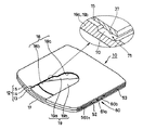
【図29】図1に示すディスク記録媒体装置の外観構成を示す斜視図である。
【図30】図29に示すディスク記録媒体装置を下面側から見たもので、シャッタ機構を閉じて開口部を閉じた状態を示す斜視図である。
【図31】図29に示すディスク記録媒体装置を下面側から見たもので、シャッタ機構を開いて開口部を開いた状態を示す斜視図である。
【図32】図29に示すディスク記録媒体装置の一対の位置決め穴を結んだ線に沿って断面した説明図である。
【図33】本発明のディスク記録媒体装置のチャッキングを説明するもので、ターンテーブルに光ディスクが装着される前の状態を断面して示す説明図である。
【図34】本発明のディスク記録媒体装置のチャッキングを説明するもので、ターンテーブルに光ディスクが装着された状態を断面して示す説明図である。
【図35】本発明のディスク記録媒体装置の開口部開閉時における上シェルに対する回転部材の昇降動作を説明するもので、同図Aは分解斜視図、同図Bはダウン時の斜視図、同図Cはアップ時の斜視図である。
【図36】本発明のディスクカートリッジの上シェルのカム部及び回転部材のカム突起間のクリアランス計算を説明するもので、上下シェル、回転部材及びシャッタ部材の寸法を符号で示した説明図である。
【図37】本発明のディスクカートリッジの上シェルのカム部及び回転部材のカム突起間のクリアランス計算を説明するもので、そのクリアランスを符号で示した説明図である。
【図38】本発明に係るディスク記録再生装置の一実施例を示す斜視図である。
【図39】本発明に係るディスク記録再生装置の送りねじ駆動装置を示すもので、動力伝達部材等の一部を断面した斜視図である。
【図40】本発明のディスク記録再生装置の回路構成の一実施例を示すブロック説明図である。
【図41】本発明のディスク記録再生装置に本発明のディスク記録媒体装置を装着する前の状態を示す斜視図である。
【図42】本発明のディスク記録再生装置に本発明のディスク記録媒体装置を装着している状態を示す斜視図である。
【図43】本発明のディスク記録媒体装置のシャッタ機構を開閉するシャッタ開閉手段の一実施例を示す斜視図である。
【図44】本発明のディスク記録媒体装置のシャッタ機構の開閉状態を説明するもので、一対のシャッタ部材が下シェルの開口部及び回転部材の開口部を完全に閉じて、ラック棒の初期動作用凸部が下シェルの開口窓に至るまでの状態を示す説明図である。
【図45】本発明のディスク記録媒体装置の下シェルを取り除いてシャッタ機構の開閉状態を説明するもので、ラック棒の初期動作用凸部が回転部材の初期動作用凹部に係合して回転部材が回り初め、一対のシャッタ部材が少々開いた状態(略5°)を示す説明図である。
【図46】本発明のディスク記録媒体装置の下シェルを取り除いてシャッタ機構の開閉状態を説明するもので、ラック棒のラック部が回転部材のギア部に噛合し、一対のシャッタ部材が大きく開いた状態(略30°)を示す説明図である。
【図47】本発明のディスク記録媒体装置の下シェルを取り除いてシャッタ機構の開閉状態を説明するもので、ラック棒のストッパ用凸部が回転部材のセット位置用凹部に係合し、一対のシャッタ部材が開口部を完全に開いた状態(略55°)を示す説明図である。
【図48】本発明のディスク記録媒体装置の第2の実施例を示すもので、分解して下面側から見た分解斜視図である。
【図49】図48に示すディスク記録媒体装置を下面側から見たもので、シャッタ機構を閉じて開口部を閉じた状態を示す斜視図である。
【図50】図48に示すディスク記録媒体装置を下面側から見たもので、シャッタ機構を開いて開口部を開いた状態を示す斜視図である。
【図51】従来のディスク記録媒体装置を示す斜視図である。
【符号の説明】
10,120 ディスク記録媒体装置、 11 光ディスク(ディスク状記録媒体)、 12 カートリッジ筐体、 13 上シェル、 14,121 回転部材、 15,122 下シェル、 16 ディスク収納室、 17,124 外側開口部、 18,123 内側開口部、 19a,19b,19A,19Bシャッタ部材、 22 カム溝、 37 リブ(凸条)、 39a,39b 操作凸部、 52 開口窓、 53 装填ガイド溝、 56 ロック部材、 60 被操作部、 64 カム突起、 70 リブ逃げ溝(凹溝)、 71 防塵用隙間、 73 ディスク記録再生装置、 74 シャーシ、 78 テーブル駆動装置、 79 光学ピックアップ装置(ピックアップ装置)、 81 ターンテーブル、 92 記録再生装置本体、 93 外装ケース、 94 カートリッジ出入口、 95 ラック棒(シャッタ開閉手段)、 97 マグネット,101,103 長溝部(凹凸部)、 102,104 突条部(凹凸部)[0001]
BACKGROUND OF THE INVENTION
The present invention relates to a disk cartridge for storing a disk-shaped recording medium such as an optical disk, a magneto-optical disk, or a magnetic disk in a disk storage chamber of a cartridge housing, and the disk-shaped recording medium is rotatably stored in advance in the disk storage chamber. The present invention relates to a disc recording medium device and a disc recording and / or reproducing device for recording and / or reproducing information using the disc recording medium device, and in particular, a pair for opening and closing an opening provided in a cartridge housing. The present invention relates to a disk cartridge, a disk recording medium apparatus, and a disk recording and / or reproducing apparatus capable of improving the dust resistance by the shutter member.
[0002]
[Prior art]
Conventionally, as a disk recording medium device in which a disk-shaped recording medium capable of recording and / or reproducing information such as audio, video, or computer data is rotatably stored in a cartridge housing, for example, FIG. The thing of the structure as shown is known. The disk
[0003]
The disk
[0004]
Further, a center hub 7 formed in a disc shape with a metal is provided at the center of the magneto-
[0005]
[Problems to be solved by the invention]
However, in the conventional disk recording medium device having such a configuration, the shutter member 6 is movably attached to the
[0006]
In recent years, with the trend of increasing the capacity and recording density of optical discs, the pitch of recording patterns has been reduced and the linear density has been increasing. For this reason, if dust or dirt adheres to the information recording surface of an optical disk or magneto-optical disk, it may interfere with the reading and writing of information by the optical pickup device, and normal information can be read and written. It may disappear.
[0007]
However, due to the further increase in capacity and recording density, the influence of reading and writing data is increased even with minute dust or dust that has been less affected by the prior art. As described above, the upper and lower shells 2a, 2a, Only by assembling the 2b layers, it was not possible to prevent the entry of fine dust or dirt. In this case, if minute dust or dust that has entered the cartridge housing 2 adheres to the information recording surface of the magneto-
[0008]
The present invention has been made in view of the above-described conventional problems. In each of the joint portions of the pair of shutter members that are joined to each other, an uneven portion is provided over substantially the entire length, and the uneven portions are engaged with each other. An object of the present invention is to provide a disc cartridge, a disc recording medium device, and a disc recording and / or reproducing device that can solve the above-described problems by closing the pair of shutter members.
[0010]
[Means for Solving the Problems]
In order to solve the above-mentioned problems and achieve the above object, In the disk cartridge of the present application, a disk storage chamber is formed between the upper shell and the rotating member or between the rotating member and the lower shell by overlapping the upper shell, the rotating member, and the lower shell. A cartridge housing that is rotatably supported by at least one and has an opening in at least one of the upper shell and the lower shell or at least one of the upper shell and the lower shell and the rotation member, and the cartridge housing A pair of shutter members that are movable between an open position that opens the opening and a closed position that closes the opening in accordance with the rotation of the rotating member, and that have joints that join each other in the closed position. Each of the joint portions of the pair of shutter members is provided with an uneven portion that can be engaged with each other over substantially the entire length of the joint portion. It is set to.
[0012]
In the disk recording medium device of the present application, a disk storage chamber is formed between the upper shell and the rotating member or between the rotating member and the lower shell by overlapping the upper shell, the rotating member, and the lower shell. A cartridge housing that is rotatably supported by at least one of the shells and that has an opening in at least one of the upper shell and the lower shell or at least one of the upper shell and the lower shell and the rotating member; A disc-shaped recording medium that is rotatably stored; Provided in the cartridge housing, according to the rotation of the rotating member A pair of shutter members that are movable between an open position that opens the opening and a closed position that closes the opening, and that have joints that join each other in the closed position, and each of the pair of shutter members The joint is characterized in that an uneven portion that can be engaged with each other is provided over substantially the entire length of the joint.
[0013]
Also, the disc recording and / or reproducing apparatus of the present application has a cartridge for rotatably storing a disc-shaped recording medium in a disc housing chamber formed in the cartridge housing and exposing a part of the disc-shaped recording medium. A disc recording medium device in which an opening provided in the housing is opened and closed by a pair of shutter members, and a shutter opening and closing that moves the pair of shutter members according to the insertion / removal operation of the disc recording medium device to open and close the openings And the disk recording medium device are detachably mounted. When the disk recording medium device is mounted, the disk recording medium device is inserted through the opening opened by the shutter opening / closing means to chuck and rotate the disk-shaped recording medium. Disk drive device And a disc housing and recording / reproducing apparatus comprising: an upper shell, a rotating member, and a lower shell, and a cartridge housing formed between the upper shell and the rotating member or between the rotating member and the lower shell. Disk storage chamber is formed in The rotating member is rotatably supported by at least one of the upper shell and the lower shell, and at least one of the upper shell and the lower shell or at least one of the upper shell and the lower shell and the rotating member are provided with an opening, The shutter member is provided in the cartridge housing, and is movable between an open position that opens the opening and a closed position that closes the opening in accordance with the rotation of the rotating member, and is joined to each other in the closed position. Have Each of the joint portions of the pair of shutter members is provided with an uneven portion that can be engaged with each other over substantially the entire length of the joint portion.
[0014]
With the configuration as described above, in the disc cartridge, the disc recording medium device, and the disc recording and / or reproducing device of the present application, the joint portion of each of the pair of shutter members has an uneven portion over substantially the entire length thereof. Since it is provided, in the closed position where the opening is closed, the joints can be firmly closed by engaging each other's concave and convex portions. As a result, the dust-proof performance of the opening by the pair of shutter members can be enhanced, and the disc-shaped recording medium stored in the cartridge housing can be prevented or effectively suppressed from entering fine dust and dirt. It is possible to provide a disc cartridge, a disc recording medium device, and a disc recording and / or reproducing device capable of preventing dust and dirt from adhering to the information recording surface and ensuring normal reading and writing of information. .
[0015]
DETAILED DESCRIPTION OF THE INVENTION
Hereinafter, embodiments of the present invention will be described with reference to the accompanying drawings. 1 to 50 show examples of the disk cartridge, disk recording medium apparatus and disk recording and / or reproducing apparatus of the present invention.
[0016]
Here, in this application, the “disc cartridge” means the upper and lower shells or the upper and lower shells and the rotating member as main constituent members, and one or a pair of shutter members (normally two, but a combination of three or more) It is also possible to have a housing formed before a disk-shaped recording medium is stored. Further, the “disc recording medium device” refers to a device comprising a combination of a cartridge housing and a disc-shaped recording medium in which the disc-shaped recording medium is accommodated in the disc accommodating chamber of the disc cartridge. Further, the “disc recording and / or reproducing device” means a combination of a disc recording medium device, a table driving device, an optical pickup device and the like.
[0017]
1 is an exploded perspective view of the first embodiment of the disk recording medium device viewed from the upper side, FIG. 2 is an exploded perspective view of the same as viewed from the lower side, FIG. 3 is a perspective view of the upper shell, and FIG. FIG. 5 is a perspective view of the chuck ring and the ring holder, FIG. 6 is a perspective view of the chuck ring and the ring holder at the center, FIG. 7 is a perspective view of the rotating member, and FIG. 8 is a plan view of the rotating member. 9 is an exploded perspective view of the pair of shutter members, FIG. 10 is an assembled perspective view of the pair of shutter members, FIG. 11 is a plan view of the first shutter member, FIG. 12 is a perspective view of the first shutter member, and FIG. , B and FIGS. 14A, 14B, and 14C are perspective views showing the main part of the first shutter member, FIG. 15 is a plan view of the second shutter member, FIG. 16 is a perspective view of the second shutter member, and FIGS. B and FIGS. 18A, 18B and 18C are oblique views showing the main part of the second shutter member. It is a diagram.
[0018]
19 is a plan view showing a state in which a pair of shutter members are mounted on the rotating member, FIG. 20 is a cross-sectional exploded perspective view taken along the line ZZ in FIG. 19, and FIG. 21 shows an opening provided in the rotating member in FIG. 22 is a perspective view showing a state in which the pair of shutter members are completely closed, FIG. 22 is a perspective view showing a state in which the rotating member is rotated approximately 5 ° from FIG. 21, and FIG. 23 is a state in which the rotating member is rotated approximately 30 ° from FIG. FIG. 24 is a perspective view showing a state in which the rotating member has been rotated by approximately 55 ° from FIG. 21, and FIG. 25 is a perspective view showing a state in which another embodiment of a pair of shutter members is mounted on the rotating member. 26A and B are perspective views of the erroneous erasure prevention device and the lock member.
[0019]
27 is a perspective view of the lower shell, FIG. 28 is a plan view of the lower shell, FIG. 29 is an assembled perspective view of the disk recording medium device viewed from above, and FIG. 30 is a shutter closed when the disk recording medium device is viewed from the lower shell side. FIG. 31 is a perspective view of the shutter opening state, FIG. 32 is a sectional view of the positioning hole portion of the disk recording medium device, and FIG. 33 is a sectional view showing the state of the disk recording medium device before chucking. 34 is a sectional view showing the chucking state, FIGS. 35A, 35B and 35C are explanatory views showing the raising / lowering operation of the rotating member. FIG. 36 is an exploded sectional view for explaining the tolerances between the upper and lower shells, the rotating member and the shutter member. FIG. 37 is an assembly sectional view for explaining the tolerance.
[0020]
38 is a perspective view showing an embodiment of a table driving device in which the disk recording medium device is used, FIG. 39 is a perspective view showing a power transmission member and the like of the feed screw power device, and FIG. 40 is a perspective view of the table driving device. FIG. 41 is a perspective view showing a state before the disk recording medium device is inserted into the table driving device, FIG. 42 is a perspective view showing the state during insertion, and FIG. FIG. 5 is a perspective view showing an embodiment of shutter opening / closing means for opening / closing a shutter of a disk recording medium device.
[0021]
44 is an explanatory view of the shutter closed state showing the relationship between the shutter mechanism of the disk cartridge and the shutter opening / closing means, and FIG. 45 is a state in which the rotating member is rotated by approximately 5 ° from the fully closed state of the shutter member with the lower shell removed. FIG. 46 is an explanatory diagram of the state in which the rotating member has rotated approximately 30 ° from the fully closed state, and FIG. 47 is an explanatory diagram of the shutter member in the fully open state (in which the rotating member has rotated approximately 55 °). 48 is an exploded perspective view of the second embodiment of the disk recording medium device viewed from the lower side, and FIG. 49 is a shutter closed state of the disk recording medium device according to the second embodiment viewed from the lower shell side. Similarly, FIG. 50 is a perspective view of the shutter open state.
[0022]
A disc
[0023]
As shown in FIGS. 1 and 2, the disk
[0024]
Since the disk
[0025]
As shown in FIGS. 1 to 4, the
[0026]
On the outer peripheral edge of the
[0027]
Further, two front
[0028]
Further, an upper recessed
[0029]
As shown in FIG. 3, the upper surface of the
[0030]
A
[0031]
The clamping
[0032]
As shown in FIGS. 33 and 34, the
[0033]
Further, the
[0034]
The inner diameter of the
[0035]
Corresponding to the shape of the
[0036]
The
[0037]
The
[0038]
Further, a
[0039]
Further, a pair of operation
[0040]
A lower
[0041]
The opening end 40a of the
[0042]
A front lower surrounding wall 42a is formed by the lower
[0043]
Further, a lower recessed
[0044]
The erroneous
[0045]
As shown in FIG. 28, front mounting holes 44a and rear mounting holes 44b for screwing the
[0046]
Further, positioning
[0047]
As shown in FIG. 32, a pair of reference holes 48, 48 are provided in the
[0048]
Each
[0049]
The rotating
[0050]
An
[0051]
In correspondence with the
[0052]
Further, a
[0053]
As shown in an enlarged view in FIG. 26B, the
[0054]
The
[0055]
The rotating
[0056]
That is, like the
[0057]
In addition, an operated
[0058]
The outer peripheral surface of the front sliding
[0059]
Since the
[0060]
Thus, the
[0061]
From this state, when the lock by the
[0062]
Further, arc-shaped
[0063]
A pair of
[0064]
The pair of
[0065]
As shown in FIGS. 11 and 15, a
[0066]
The
[0067]
As shown in FIGS. 11 to 14, the convex-side
[0068]
As shown in FIGS. 16 to 18, the convex
[0069]
As shown in FIGS. 14C, 17A, 17B, and 20, the
[0070]
In addition, a guide
[0071]
Furthermore, a center-side
[0072]
Further, as shown in FIG. 11 and FIG. 15 and the like, the
[0073]
Further, the pair of
[0074]
The purpose of the
[0075]
Thus, as shown in FIG. 10, by combining a pair of
[0076]
The pair of
[0077]
Contrary to this embodiment, the
[0078]
As shown in FIG. 21, the pair of
[0079]
That is, when the
[0080]
In this
[0081]
The
[0082]
Examples of the material of the
[0083]
The disk
[0084]
Next, the opening side of the rotating
[0085]
The
[0086]
Next, the
[0087]
At the same time or before and after this, the erroneous
[0088]
Next, the
[0089]
At this time, by setting the pair of
[0090]
Thereafter, the
[0091]
According to the disk
[0092]
Such a disc
[0093]
The
[0094]
A
[0095]
The disc recording / reproducing
[0096]
The
[0097]
As shown in FIGS. 33 and 34, the
[0098]
As shown in FIG. 38, a pair of
[0099]
The
[0100]
The
[0101]
The optical head of the
[0102]
Of the pair of
[0103]
As shown in an enlarged view in FIG. 39, the feed
[0104]
The
[0105]
The
[0106]
Further, the
[0107]
The
[0108]
The first nut member 90a has a nut main body formed in a block shape and a cylindrical tube shaft portion formed continuously on one surface side of the nut main body, and one axial hole passing therethrough. The
[0109]
Further, the
[0110]
The first and
[0111]
In this case, both the
[0112]
As a result, in FIG. 39, in the screw portion of the first nut member 90a, the left screw surface in the drawing is pressed against the left screw surface of the
[0113]
Further, the first nut member 90a is provided with a
[0114]
The fixed piece 91a is made of an elongated plate material, and an L-shaped
[0115]
The
[0116]
As the material of the
[0117]
The pair of
[0118]
Next, the recording / reproducing apparatus
[0119]
The system controller S1 and the memory controller S5 are directly connected, and a read-only storage device (ROM) S2 and a read / write storage device (RAM) S3 are connected to the connection line. In addition, the memory controller S5 is connected to the memory S4 and an encoder S6 for MPEG2 (moving image compression system applicable to existing TV broadcasting, HDTV, broadband ISDN, etc. supporting 3M to 40Mbps) and a decoder S7 for MPEG2. Has been. Furthermore, a control panel S8 and a remote control receiver S9 are connected to the system controller S1.
[0120]
Further, an error correction processing circuit (ECC) D4 is connected to the drive controller D1, and a storage device (ROM) D2, a storage device (RAM) D3, a servo circuit D6, and an address decoder D7 are connected to the connection line. Has been. Further, a recording error determination circuit D8 for determining a recording error is connected to the drive controller D1. The drive controller D1 is connected to the system controller S1 via a command interface.
[0121]
The correction processing circuit D4 is connected to the memory controller S5 via the data interface and is also connected to the modulation / demodulation circuit D5. The modem circuit D5 is connected to an optical head having an
[0122]
The recording / reproducing apparatus
[0123]
[0124]
The open / close door 94a is biased to the closing side by a spring (not shown), and as shown in FIG. 42, the open / close door 94a is pressed to the predetermined position by pressing the open / close door 94a at the front portion of the disk
[0125]
A
[0126]
The front
[0127]
Further, the initial operation
[0128]
With reference to FIGS. 41, 42, and 44 to 47, the rotation of the rotating
[0129]
As shown in FIG. 41, the inner and
[0130]
First, as shown in FIGS. 42 and 44, when a predetermined amount of the disk
[0131]
Next, as shown in FIG. 45, the disc
[0132]
When the
[0133]
Then, as shown in FIG. 46, before the meshing between the
[0134]
In this case, as described above, the
[0135]
Further, in the set state of the disk
[0136]
Therefore, the
[0137]
Further, the pair of
[0138]
Thus, the pair of
[0139]
As a result, the disk
[0140]
As a result, the
[0141]
Thereby, the
[0142]
As a result, the
[0143]
At the same time, the optical head of the
[0144]
Therefore, the table driving device
[0145]
Next, the case where the disk
[0146]
For example, in a state where the disk
[0147]
Further, the
[0148]
Thereafter, when the disc
[0149]
At this time, since the tip of the convex portion 96b has entered the
[0150]
By the rotation of the rotating
[0151]
On the other hand, since the relative movement continues between the disk
[0152]
After that, the initial operation
[0153]
At this time, the pair of
[0154]
Due to the spring force of the
[0155]
In particular, in the present embodiment, the projections 102 (or 104) provided on the other shutter member are engaged with the long groove portions 101 (or 103) provided on the one shutter member so that the joint portions are uneven. Since the connecting
[0156]
Further, in the shutter closed state, the protrusion portion 102 (or 104) is engaged with the long groove portion 101 (or 103), so that the joining
[0157]
In the above embodiment, the
[0158]
In this way, the
[0159]
In such a disk
[0160]
(1) A: Height from the end surface of the
A = 2.9mm + 0.1 / 0mm
(2) B: Height from the end surface such as the upper
B = 3.85mm ± 0.05mm (reference dimension)
(3) C: Height from the end surface to the bottom surface of the lower
C = 4.15mm + 0.1 / -0mm (reference dimension)
(4) D: Height from the end surface to the bottom surface of the lower
D = 3.3mm ± 0.05mm
(5) E: Thickness of the
E = 1.1mm + 0 / -0.05mm
[0161]
(6) F: Height from the lower surface to the end surface of the rotating
F = 4.7 mm + 0 / −0.1 mm
(7) G: Height of the
G = 0.2mm + 0 / -0.05mm
(8) H: Height of the
H = 0.2mm + 0 / -0.05mm
(9) J: Height of the
J = 0.2mm + 0 / -0.05mm (reference dimension)
(10) K: Depth of the
K = 0.2mm + 0.05 / -0mm (reference dimension)
[0162]
(11) Σ: Ideal clearance between the
Σ = −H + A + D−E−F−G (1)
= 0mm + 0.45 / -0mm (cumulative tolerance)
0.064mm + 0.322 / -0mm (root mean square x 1.66)
[0163]
As is apparent from the calculation formula (1), the ideal clearance Σ is preferably 0 mm to 0.45 mm, and the most preferable value is about 0.2 mm.
In this embodiment, the rotating
[0164]
In the present embodiment, ribs 37 (arc-shaped
[0165]
In addition, although the uneven | corrugated | grooved part provided in the
[0166]
Further, the cartridge housing can be constituted by a combination of upper and lower shells by eliminating the rotating member. Then, as shown in FIG. 51 shown as a conventional example, a shutter member that linearly moves to open and close the opening may be provided. By providing the cartridge housing having such a configuration with the
[0167]
FIG. 25 shows another embodiment of the pair of
[0168]
The guide
[0169]
48 to 50 show a second embodiment of the disk cartridge and disk recording medium apparatus of the present invention. The disc
[0170]
As apparent from FIGS. 48 to 50, this disk
[0171]
The
[0172]
Similarly to the
[0173]
Thus, by using the two-
[0174]
Note that the
[0175]
As described above, the present invention is not limited to the above-described embodiment. For example, in the above-described embodiment, an example in which an optical disk is used as an information recording medium has been described. The present invention can be applied to various magnetic disks and other various disk-shaped recording media. Furthermore, in the above-described embodiment, the example applied to the disk recording / reproducing apparatus capable of both recording and reproducing as the disk recording and / or reproducing apparatus has been described. Of course, the present invention can be applied to a disk reproducing apparatus.
[0176]
In the above-described embodiment, the example in which the opening
[0177]
Furthermore, in the above-described embodiment, the example in which the
[0178]
In the above-described embodiment, an example in which the opening / closing portion is opened / closed by moving the disk recording medium device with the shutter opening / closing means fixed while opening / closing the shutter has been described. Any structure may be used as long as the means and the disk cartridge are moved relatively to open and close the shutter member. For example, after the disk recording medium device is fixed to the disk mounting portion, the shutter opening / closing means may be moved by a motor or the like to be opened / closed. As described above, the present invention can be variously modified without departing from the spirit of the present invention.
[0179]
【The invention's effect】
As described above, according to the disk cartridge of the present application, the cartridge housing (a combination of the upper shell, the rotating member, and the lower shell) having the disk storage chamber and the pair of shutter members that open and close the opening are provided. In the disc cartridge, since the concave and convex portions are provided over substantially the entire length of each joint portion of the pair of shutter members, the concave and convex portions are engaged with each other at the closed position where the opening portion is closed. The joint can be tightly closed. As a result, the dustproof performance of the opening by the pair of shutter members can be enhanced, and the entry of minute size dust or dirt can be prevented or effectively suppressed. Therefore, it is possible to provide a disk cartridge that can prevent dust and dirt from adhering to the information recording surface of the disk-shaped recording medium housed in the cartridge housing.
[0180]
According to the disk recording medium device of the present application, each of the pair of shutter members includes a cartridge housing having a disk storage chamber, a disk-shaped recording medium, and a pair of shutter members that open and close the opening. Since the concavo-convex portion is provided in the joint portion over the substantially entire length, the concavo-convex portions can be engaged with each other at the closed position where the opening is closed, and the joint portions of the pair of shutter members can be tightly closed. . As a result, the dustproof performance of the opening by the pair of shutter members can be enhanced, and the entry of minute size dust or dirt can be prevented or effectively suppressed. Therefore, it is possible to provide a disk recording medium device that can prevent dust and dirt from adhering to the information recording surface of the disk-shaped recording medium housed in the cartridge housing.
[0181]
According to the disk recording and / or reproducing apparatus of the present application, a disk recording medium having a disk storage chamber for storing a disk-shaped recording medium and a pair of shutter members that open and close an opening for exposing a part of the disk-shaped recording medium. Device, shutter opening / closing means for opening / closing a pair of shutter members, and disk-shaped recording medium for chucking and rotating Disk drive device In the disc recording and / or reproducing apparatus provided with the above, the concave and convex portions are provided at the joint portions of the pair of shutter members over substantially the entire length thereof. The joint portions of the pair of shutter members can be firmly closed together. As a result, the dust-proof performance of the opening portion by the pair of shutter members can be enhanced, and entry of minute size dust, dust, etc. can be prevented or effectively suppressed, and stored in the cartridge housing. Information signals can be recorded and reproduced using a disk recording medium device that can prevent dust and dirt from adhering to the information recording surface of the disk-shaped recording medium. Therefore, there is an effect that it is possible to provide a disc recording and / or reproducing device that can read and write normal information.
[Brief description of the drawings]
FIG. 1 is an exploded perspective view showing a first embodiment of a disk recording medium device according to the present invention, as seen from the top side.
FIG. 2 is an exploded perspective view showing the first embodiment of the disk recording medium device of the present invention, as seen from the underside when disassembled.
FIG. 3 is a perspective view of an upper shell of a disk cartridge according to the disk recording medium apparatus of the present invention as viewed from the upper surface side.
FIG. 4 is a bottom view of the upper shell of the disk cartridge according to the disk recording medium device of the present invention.
FIG. 5 is a perspective view of a chuck ring and a ring holder attached to an upper shell of a disk cartridge according to the disk recording medium apparatus of the present invention as viewed from the upper surface side.
FIG. 6 is a perspective view of a central portion of a chuck ring and a ring holder attached to an upper shell of a disk cartridge according to the disk recording medium device of the present invention, as viewed from the lower surface side.
FIG. 7 is a perspective view of a rotating member of a disk cartridge according to the disk recording medium device of the present invention as viewed from the upper surface side.
FIG. 8 is a plan view of a rotating member of a disk cartridge according to the disk recording medium device of the present invention.
FIG. 9 is a perspective view of a first embodiment of a pair of shutter members of a disk cartridge according to the disk recording medium device of the present invention as viewed from the back side.
FIG. 10 is a perspective view of the combination state of the first embodiment of the pair of shutter members of the disk cartridge according to the disk recording medium device of the present invention as seen from the back side.
11 is a plan view of the first shutter member of the pair of shutter members shown in FIG. 9 as viewed from the front side.
12 is a perspective view of the first shutter member shown in FIG. 11. FIG.
13 is an enlarged view of a main part of the first shutter member shown in FIG. 12, in which FIG. A is a perspective view of the T portion viewed from the front surface side, and FIG. FIG.
14 is an enlarged view of the main part of the first shutter member shown in FIG. 12. FIG. 14A is a perspective view of the U portion viewed from the front surface side, and FIG. FIG. 3C is a perspective view of the V portion viewed from the front side.
15 is a plan view of a second shutter member of the pair of shutter members shown in FIG. 9 as viewed from the front surface side.
16 is a perspective view of the second shutter member shown in FIG.
17 is an enlarged view of the main part of the second shutter member shown in FIG. 16. FIG. 17A is a perspective view of the W portion as viewed from the front surface side, and FIG. FIG.
18 is an enlarged view of a main part of the second shutter member shown in FIG. 16. FIG. 18A is a perspective view of the X portion viewed from the surface side, and FIG. 18B shows the Y portion viewed from the surface side. FIG. 6C is a perspective view of the Y portion viewed from the back side.
19 is a plan view showing a state in which a pair of shutter members are attached to the rotating member of the disk recording medium device shown in FIG. 1 and the inner opening is closed. FIG.
20 is a perspective view showing a pair of shutter members in a state where a ZZ line portion in FIG. 19 is sectioned and separated. FIG.
21 is a perspective view showing a state where a pair of shutter members are attached to the rotating member of the disk recording medium device shown in FIG. 1 and the inner opening is closed. FIG.
22 is an explanatory diagram showing a state (approximately 5 °) in which the pair of shutter members is slightly opened for the first time when the rotating member rotates from the state shown in FIG.
23 is an explanatory view showing a state (approximately 30 °) in which the rotating member is rotated and the pair of shutter members are largely opened from the state shown in FIG.
24 is an explanatory diagram showing a state (approximately 55 °) in which the rotating member has rotated greatly from the state shown in FIG. 21 and the pair of shutter members have completely opened the opening.
25 shows a second embodiment of the shape of the pair of shutter members shown in FIG. 22, and is an explanatory view (corresponding to FIG. 22) in which a large amount of overlap in the plane direction is set.
FIG. 26A is a perspective view of a disk cartridge according to the disk recording medium apparatus of the present invention as viewed from the upper surface side, and FIG.
FIG. 27 is a perspective view of the lower shell of the disk cartridge according to the disk recording medium device of the present invention as viewed from the upper surface side.
FIG. 28 is a plan view of a lower shell of a disk cartridge according to the disk recording medium device of the present invention.
29 is a perspective view showing an external configuration of the disk recording medium device shown in FIG. 1. FIG.
30 is a perspective view showing a state in which the disc recording medium device shown in FIG. 29 is viewed from the lower surface side, and the shutter mechanism is closed and the opening is closed. FIG.
31 is a perspective view showing the disk recording medium device shown in FIG. 29 as viewed from the lower surface side and showing a state in which the shutter mechanism is opened and the opening is opened. FIG.
32 is an explanatory view taken along a line connecting a pair of positioning holes of the disk recording medium device shown in FIG. 29;
FIG. 33 is a diagram illustrating the chucking of the disk recording medium device according to the present invention, and is a cross-sectional view illustrating a state before the optical disk is mounted on the turntable.
FIG. 34 is a diagram illustrating the chucking of the disk recording medium device according to the present invention, and is a cross-sectional view illustrating a state where the optical disk is mounted on the turntable.
FIGS. 35A and 35B are diagrams for explaining the lifting and lowering operation of the rotating member relative to the upper shell when the opening of the disk recording medium device of the present invention is opened and closed. FIG. 35A is an exploded perspective view, and FIG. FIG. C is a perspective view when up.
FIG. 36 is a diagram for explaining the clearance calculation between the cam portion of the upper shell of the disk cartridge of the present invention and the cam projection of the rotating member, and is an explanatory diagram showing the dimensions of the upper and lower shells, the rotating member, and the shutter member by reference numerals. .
FIG. 37 is a diagram for explaining the clearance calculation between the cam portion of the upper shell of the disk cartridge of the present invention and the cam protrusion of the rotating member, and is an explanatory diagram showing the clearance by reference numerals.
FIG. 38 is a perspective view showing an embodiment of a disc recording / reproducing apparatus according to the present invention.
FIG. 39 is a perspective view showing a cross section of a part of a power transmission member and the like, showing a feed screw driving device of a disk recording / reproducing apparatus according to the present invention.
FIG. 40 is a block diagram showing an embodiment of the circuit configuration of the disk recording / reproducing apparatus of the present invention.
FIG. 41 is a perspective view showing a state before the disk recording medium device of the present invention is mounted on the disk recording / reproducing apparatus of the present invention.
FIG. 42 is a perspective view showing a state in which the disk recording medium device of the present invention is mounted on the disk recording / reproducing apparatus of the present invention.
FIG. 43 is a perspective view showing an embodiment of shutter opening / closing means for opening and closing the shutter mechanism of the disk recording medium device of the present invention.
FIG. 44 explains the open / closed state of the shutter mechanism of the disk recording medium device of the present invention, in which the pair of shutter members completely closes the opening of the lower shell and the opening of the rotating member, and the initial operation of the rack bar. It is explanatory drawing which shows the state until a convex part reaches for the opening window of a lower shell.
FIG. 45 is for explaining the open / close state of the shutter mechanism by removing the lower shell of the disk recording medium device of the present invention, in which the initial operation convex portion of the rack bar engages with the initial operation concave portion of the rotating member and rotates. It is explanatory drawing which shows the state (substantially 5 degrees) which a member began to rotate and a pair of shutter member opened a little.
FIG. 46 illustrates the open / close state of the shutter mechanism by removing the lower shell of the disk recording medium device of the present invention. The rack portion of the rack bar meshes with the gear portion of the rotating member, and the pair of shutter members opens widely. It is explanatory drawing which shows the state (substantially 30 degrees).
FIG. 47 explains the open / closed state of the shutter mechanism by removing the lower shell of the disk recording medium device of the present invention, wherein the stopper convex portion of the rack bar engages with the set position concave portion of the rotating member, It is explanatory drawing which shows the state (substantially 55 degrees) which the shutter member opened the opening part completely.
FIG. 48 is a disassembled perspective view showing the second embodiment of the disk recording medium device of the present invention, which is disassembled and viewed from the lower surface side.
49 is a perspective view showing the disk recording medium device shown in FIG. 48 as viewed from the lower surface side and showing a state in which the shutter mechanism is closed and the opening is closed. FIG.
50 is a perspective view showing a state in which the disc recording medium device shown in FIG. 48 is viewed from the lower surface side and a shutter mechanism is opened and an opening is opened. FIG.
FIG. 51 is a perspective view showing a conventional disk recording medium device.
[Explanation of symbols]
10, 120 disc recording medium device, 11 optical disc (disc-shaped recording medium), 12 cartridge housing, 13 upper shell, 14, 121 rotating member, 15, 122 lower shell, 16 disc storage chamber, 17, 124 outer opening, 18, 123 inner opening, 19a, 19b, 19A, 19B shutter member, 22 cam groove, 37 rib (projection), 39a, 39b operation protrusion, 52 opening window, 53 loading guide groove, 56 lock member, 60 covered Operation unit, 64 cam projection, 70 rib escape groove (concave groove), 71 dust-proof gap, 73 disc recording / reproducing device, 74 chassis, 78 table drive device, 79 optical pickup device (pickup device), 81 turntable, 92 recording Reproduction device main body, 93 outer case, 94 cartridge inlet / outlet, 95 Click bars (shutter opening and closing means), 97 magnets, 101 and 103 long groove (uneven portion), 102 and 104 ridges (uneven portion)
Claims (31)
上記カートリッジ筐体に設けられ、上記回転部材の回転に応じて上記開口部を開く開位置と当該開口部を閉じる閉位置との間に移動可能とされると共に、上記閉位置において互いに接合する接合部を有する一対のシャッタ部材と、を備え、
上記一対のシャッタ部材の各々の接合部には、互いに係合可能な凹凸部を当該接合部の略全長に渡って設けた
ことを特徴とするディスクカートリッジ。A disk storage chamber is formed between the upper shell and the rotating member or between the rotating member and the lower shell by overlapping the upper shell, the rotating member, and the lower shell, and the rotating member is rotated by at least one of the upper shell and the lower shell. A cartridge housing that is supported freely and has an opening in at least one of the upper shell and the lower shell or at least one of the upper shell and the lower shell and the rotating member;
A joint that is provided in the cartridge housing and is movable between an open position that opens the opening and a closed position that closes the opening in response to the rotation of the rotating member, and is joined to each other in the closed position. A pair of shutter members having a portion,
The disc cartridge according to claim 1, wherein each joint portion of the pair of shutter members is provided with a concavo-convex portion that can be engaged with each other over substantially the entire length of the joint portion.
ことを特徴とする請求項1記載のディスクカートリッジ。Of the pair of shutter members, the concavo-convex portion provided at the joint portion of one shutter member is a V-groove or square groove-like long groove portion, and the concavo-convex portion provided at the joint portion of the other shutter member is a wedge shape. The disk cartridge according to claim 1 , wherein the disk cartridge is a rectangular protrusion.
ことを特徴とする請求項1記載のディスクカートリッジ。Of the pair of shutter members, the concavo-convex portion provided at the joint of one shutter member is a combination of a long groove portion having a V-groove shape or a square groove shape and a wedge-shaped or ridge shape protrusion portion, and the other shutter member. The concavo-convex portion provided at the joint portion of the member is formed by a combination of a ridge portion and a long groove portion which can be engaged with each other corresponding to the long groove portion and the ridge portion of the one shutter member. 1. The disk cartridge according to 1 .
ことを特徴とする請求項1記載のディスクカートリッジ。The pair of each of the joint portions of the shutter member, the disc cartridge according to claim 1, characterized in that it consists of the combination of the long groove portion of the mutually engageable V groove shape or square groove shape.
ことを特徴とする請求項1記載のディスクカートリッジ。The pair of shutter members, to at least one of said upper shell and said lower shell, according to claim 1, characterized in that it is rotatably supported rotates about the fulcrum corresponding to each of the shutter member Disc cartridge.
ことを特徴とする請求項1記載のディスクカートリッジ。It said pair of shutter members, the disc cartridge according to claim 1, wherein the relative said rotating member, and is rotatably supported rotates about the fulcrum corresponding to each of the shutter members.
ことを特徴とする請求項1記載のディスクカートリッジ。The pair of shutter members are rotatably supported with respect to the rotating member around a fulcrum corresponding to each shutter member, and at least one of the upper shell and the lower shell, respectively. The disc cartridge according to claim 1 , wherein the disc cartridge is slidably supported by a fulcrum corresponding to the shutter member.
ことを特徴とする請求項1記載のディスクカートリッジ。Each of the pair of shutter members is formed of a substantially semicircular plate, and the pair of shutter members sandwich the opening between at least one surface of the rotating member, the upper shell, and the lower shell having the opening. The disk cartridge according to claim 1 , wherein the disk cartridge is disposed so as to face each other.
ことを特徴とする請求項8記載のディスクカートリッジ。The pair of shutter members, one side of the chord side while being rotatably supported on the rotary member in each of the shutter member, provided in the opening and closing groove provided on the shutter member to the lower shell or the upper shell The disc cartridge according to claim 8, wherein the operation convex portion is slidably engaged.
ことを特徴とする請求項9記載のディスクカートリッジ。The concavo-convex portions of the pair of shutter members are provided in a long groove portion provided in substantially half of the support side of one side portion of the string side and in substantially half of tip end side of the one side portion of the string side. The disk cartridge according to claim 9, comprising a protrusion.
上記ディスク収納室内に回転自在に収納されるディスク状記録媒体と、
上記カートリッジ筐体に設けられ、上記回転部材の回転に応じて上記開口部を開く開位置と当該開口部を閉じる閉位置との間に移動可能とされると共に、上記閉位置において互いに接合する接合部を有する一対のシャッタ部材と、を備え、
上記一対のシャッタ部材の各々の接合部には、互いに係合可能な凹凸部を当該接合部の略全長に渡って設けた
ことを特徴とするディスク記録媒体装置。A disk storage chamber is formed between the upper shell and the rotating member or between the rotating member and the lower shell by overlapping the upper shell, the rotating member, and the lower shell, and the rotating member is rotated by at least one of the upper shell and the lower shell. A cartridge housing that is supported freely and has an opening in at least one of the upper shell and the lower shell or at least one of the upper shell and the lower shell and the rotating member;
A disk-shaped recording medium that is rotatably stored in the disk storage chamber;
A joint that is provided in the cartridge housing and is movable between an open position that opens the opening and a closed position that closes the opening in accordance with the rotation of the rotating member, and is joined to each other in the closed position. A pair of shutter members having a portion,
The disc recording medium device according to claim 1, wherein each of the joint portions of the pair of shutter members is provided with an uneven portion that can be engaged with each other over substantially the entire length of the joint portion.
ことを特徴とする請求項11記載のディスク記録媒体装置。Of the pair of shutter members, the concavo-convex portion provided at the joint portion of one shutter member is a V-groove or square groove-like long groove portion, and the concavo-convex portion provided at the joint portion of the other shutter member is a wedge shape. The disk recording medium device according to claim 11 , wherein the disk recording medium device is an angular protrusion.
ことを特徴とする請求項11記載のディスク記録媒体装置。Of the pair of shutter members, the concavo-convex portion provided at the joint portion of one shutter member is a combination of a long groove portion having a V-groove shape or a square groove shape and a wedge-shaped or ridge shape protrusion portion, and the other shutter member. The concavo-convex portion provided at the joint portion of the member is formed by a combination of a ridge portion and a long groove portion which can be engaged with each other corresponding to the long groove portion and the ridge portion of the one shutter member. 11. The disk recording medium device according to 11 .
ことを特徴とする請求項11記載のディスク記録媒体装置。The disk recording medium device according to claim 11 , wherein each joint portion of the pair of shutter members is a combination of a long groove portion having a V-groove shape or a square groove shape that can be engaged with each other.
ことを特徴とする請求項11記載のディスク記録媒体装置。The pair of shutter members, to at least one of said upper shell and said lower shell, according to claim 11, characterized in that it is rotatably supported rotates about the fulcrum corresponding to each of the shutter member Disc recording medium device.
ことを特徴とする請求項11記載のディスク記録媒体装置。The disk recording medium device according to claim 11 , wherein the pair of shutter members are supported so as to be rotatable about the fulcrum corresponding to each shutter member with respect to the rotating member.
ことを特徴とする請求項11記載のディスク記録媒体装置。The pair of shutter members are supported rotatably with respect to the rotating member around a fulcrum corresponding to each shutter member, and at least one of the upper shell and the lower shell, respectively. The disk recording medium device according to claim 11 , wherein the disk recording medium device is slidably supported by a fulcrum corresponding to the shutter member.
ことを特徴とする請求項11記載のディスク記録媒体装置。Each of the pair of shutter members is made of a substantially semicircular plate, and the pair of shutter members sandwich the opening between at least one surface of the rotating member, the upper shell, or the lower shell having the opening. The disk recording medium device according to claim 11 , wherein the disk recording medium device is disposed so as to face each other.
ことを特徴とする請求項18記載のディスク記録媒体装置。The pair of shutter members, one side of the chord side while being rotatably supported on the rotary member in each of the shutter member, provided in the opening and closing groove provided on the shutter member to the lower shell or the upper shell The disk recording medium device according to claim 18, wherein the operation projections are slidably engaged.
ことを特徴とする請求項19記載のディスク記録媒体装置。The concavo-convex portions of the pair of shutter members are provided in a long groove portion provided in substantially half of the support side of one side portion of the string side and in substantially half of tip end side of the one side portion of the string side. The disk recording medium device according to claim 19, comprising a protrusion.
上記ディスク記録媒体装置の挿脱動作に応じて上記一対のシャッタ部材を移動させて上記開口部を開閉させるシャッタ開閉手段と、
上記ディスク記録媒体装置が着脱可能に装着されると共に、当該ディスク記録媒体装置の装着時、上記シャッタ開閉手段で開放された上記開口部から挿入されて上記ディスク状記録媒体をチャッキングして回転駆動するディスクドライブ装置と、を備えたディスク記録及び/又は再生装置において、
上記カートリッジ筐体は、上シェル、回転部材及び下シェルを重ね合わせることによって構成されると共に、上シェル及び回転部材間若しくは回転部材及び下シェル間に上記ディスク収納室が形成され、上記回転部材が上記上シェル及び上記下シェルの少なくとも一方によって回転自在に支持されると共に、上記上シェル及び上記下シェルの少なくとも一方又は上記上シェル及び上記下シェルの少なくとも一方と上記回転部材とに上記開口部が設けられ、
上記一対のシャッタ部材は、上記カートリッジ筐体に設けられ、上記回転部材の回転に応じて上記開口部を開く開位置と当該開口部を閉じる閉位置との間に移動可能とされると共に、上記閉位置において互いに接合する接合部を有し、
上記一対のシャッタ部材の各々の接合部には、互いに係合可能な凹凸部を当該接合部の略全長に渡って設けた
ことを特徴とするディスク記録及び/又は再生装置。A disc-shaped recording medium is rotatably accommodated in a disc housing chamber formed in the cartridge casing, and an opening provided in the cartridge casing for exposing a part of the disc-shaped recording medium is a pair of shutter members. A disk recording medium device that can be freely opened and closed by
Shutter opening / closing means for opening / closing the opening by moving the pair of shutter members in accordance with an insertion / removal operation of the disk recording medium device;
The disk recording medium device is detachably mounted, and when the disk recording medium device is mounted, the disk recording medium device is inserted through the opening opened by the shutter opening / closing means and chucked to rotate the disk recording medium. in the disc recording and / or reproducing apparatus comprising: a disk drive apparatus, the for,
The cartridge housing is configured by overlapping an upper shell, a rotating member, and a lower shell, and the disk storage chamber is formed between the upper shell and the rotating member or between the rotating member and the lower shell, and the rotating member is The opening is rotatably supported by at least one of the upper shell and the lower shell, and at least one of the upper shell and the lower shell, or at least one of the upper shell and the lower shell, and the rotating member. Provided,
The pair of shutter members are provided in the cartridge housing and are movable between an open position for opening the opening and a closed position for closing the opening in accordance with the rotation of the rotating member. Having joints that join together in a closed position;
The disc recording and / or reproducing apparatus according to any one of claims 1 to 8, wherein each joint portion of the pair of shutter members is provided with a concavo-convex portion that can be engaged with each other over substantially the entire length of the joint portion.
ことを特徴とする請求項21記載のディスク記録及び/又は再生装置。Of the pair of shutter members, the concavo-convex portion provided at the joint portion of one shutter member is a long groove portion having a V-groove shape or a square groove shape, and the concavo-convex portion provided at the joint portion of the other shutter member is a wedge shape. The disk recording and / or reproducing apparatus according to claim 21 , wherein the disk recording and / or reproducing apparatus is a rectangular protrusion.
ことを特徴とする請求項21記載のディスク記録及び/又は再生装置。Of the pair of shutter members, the concavo-convex portion provided at the joint portion of one shutter member is a combination of a long groove portion having a V-groove shape or a square groove shape and a wedge-shaped or ridge shape protrusion portion, and the other shutter member. The concavo-convex portion provided at the joint portion of the member is formed by a combination of a ridge portion and a long groove portion which can be engaged with each other corresponding to the long groove portion and the ridge portion of the one shutter member. 21. The disk recording and / or reproducing device according to 21 .
ことを特徴とする請求項21記載のディスク記録及び/又は再生装置。The disk recording and / or reproducing apparatus according to claim 21 , wherein each joint portion of the pair of shutter members is a combination of long groove portions that can be engaged with each other.
ことを特徴とする請求項21記載のディスク記録及び/又は再生装置。The pair of shutter members, to at least one of said upper shell and said lower shell, according to claim 21, wherein the being rotatably supported rotates about the fulcrum corresponding to each of the shutter member Disc recording and / or playback device.
ことを特徴とする請求項21記載のディスク記録及び/又は再生装置。The disk recording and / or reproducing apparatus according to claim 21 , wherein the pair of shutter members are supported by the rotating member so as to be rotatable about a fulcrum corresponding to each shutter member. .
ことを特徴とする請求項21記載のディスク記録及び/又は再生装置。The pair of shutter members are rotatably supported with respect to the rotating member around a fulcrum corresponding to each shutter member, and at least one of the upper shell and the lower shell, respectively. The disk recording and / or reproducing apparatus according to claim 21 , wherein the disk recording and / or reproducing apparatus is slidably supported by a fulcrum corresponding to the shutter member.
ことを特徴とする請求項21記載のディスク記録及び/又は再生装置。Each of the pair of shutter members is made of a substantially semicircular plate, and the pair of shutter members sandwich the opening between at least one surface of the rotating member, the upper shell, or the lower shell having the opening. The disk recording and / or reproducing apparatus according to claim 21 , wherein the disk recording and / or reproducing apparatus is arranged so as to face each other.
ことを特徴とする請求項28記載のディスク記録及び/又は再生装置。The pair of shutter members are rotatably supported by the rotating member on one side of the string side of each shutter member, and provided in the lower shell or the upper shell in an opening / closing groove provided in the shutter member. 29. The disc recording and / or reproducing apparatus according to claim 28, wherein the operation convex portion is slidably engaged.
ことを特徴とする請求項29記載のディスク記録及び/又は再生装置。The concavo-convex portions of the pair of shutter members are provided in a long groove portion provided in substantially half of the support side of one side portion of the string side and in substantially half of tip end side of the one side portion of the string side. 30. The disc recording and / or reproducing apparatus according to claim 29, comprising a protrusion.
上記回転部材は上記ラック部に噛合されるギア部と当該ギア部の前後に配置された凹部を有し、
上記シャッタ開閉手段の進退運動に基づいて上記回転部材に回転運動を付与するようにした
ことを特徴とする請求項21記載のディスク記録及び/又は再生装置。The shutter opening / closing means has a rack portion and convex portions arranged before and after the rack portion,
The rotating member has a gear portion meshed with the rack portion, and concave portions arranged in front and rear of the gear portion,
The disk recording and / or reproducing device according to claim 21 , wherein a rotational motion is imparted to the rotating member based on a forward / backward motion of the shutter opening / closing means.
Priority Applications (1)
| Application Number | Priority Date | Filing Date | Title |
|---|---|---|---|
| JP2002255236A JP4089357B2 (en) | 2001-09-21 | 2002-08-30 | Disc cartridge, disc recording medium device, and disc recording and / or reproducing device |
Applications Claiming Priority (3)
| Application Number | Priority Date | Filing Date | Title |
|---|---|---|---|
| JP2001289286 | 2001-09-21 | ||
| JP2001-289286 | 2001-09-21 | ||
| JP2002255236A JP4089357B2 (en) | 2001-09-21 | 2002-08-30 | Disc cartridge, disc recording medium device, and disc recording and / or reproducing device |
Publications (3)
| Publication Number | Publication Date |
|---|---|
| JP2003168276A JP2003168276A (en) | 2003-06-13 |
| JP2003168276A5 JP2003168276A5 (en) | 2007-05-10 |
| JP4089357B2 true JP4089357B2 (en) | 2008-05-28 |
Family
ID=26622698
Family Applications (1)
| Application Number | Title | Priority Date | Filing Date |
|---|---|---|---|
| JP2002255236A Expired - Lifetime JP4089357B2 (en) | 2001-09-21 | 2002-08-30 | Disc cartridge, disc recording medium device, and disc recording and / or reproducing device |
Country Status (1)
| Country | Link |
|---|---|
| JP (1) | JP4089357B2 (en) |
Families Citing this family (1)
| Publication number | Priority date | Publication date | Assignee | Title |
|---|---|---|---|---|
| US7251104B2 (en) | 2003-06-23 | 2007-07-31 | Sony Corporation | Recording medium cartridge |
-
2002
- 2002-08-30 JP JP2002255236A patent/JP4089357B2/en not_active Expired - Lifetime
Also Published As
| Publication number | Publication date |
|---|---|
| JP2003168276A (en) | 2003-06-13 |
Similar Documents
| Publication | Publication Date | Title |
|---|---|---|
| JP4089140B2 (en) | Disc cartridge | |
| EP1156488B1 (en) | Disc cartridges | |
| KR100746734B1 (en) | Disk cartridge | |
| KR100897978B1 (en) | Disc cartridge, disc recording medium apparatus, and disc recording and/or reproducing apparatus | |
| JP3991642B2 (en) | Disc cartridge, disc recording medium device, and disc recording / reproducing device | |
| KR100897976B1 (en) | Disk cartridge, disk recording medium device, and a device which performs at least one of disk recording and reproducing | |
| JP4089357B2 (en) | Disc cartridge, disc recording medium device, and disc recording and / or reproducing device | |
| JP4131145B2 (en) | Disc cartridge, disc recording medium device, and disc recording and / or reproducing device | |
| KR20040029956A (en) | Disk cartridge, disk recording medium device, and disk recording and/or reproducing device | |
| JP2003085916A (en) | Disk cartridge, disk recording medium device and disk recording and reproducing device | |
| JP2001332058A (en) | Disk cartridge | |
| JP3991560B2 (en) | Disc cartridge | |
| JP2001283558A (en) | Disk cartridge | |
| JP2002050147A (en) | Disk cartridge | |
| JP2003085917A (en) | Disk cartridge, disk recording medium device and disk recording and reproducing device | |
| JP3601480B2 (en) | Disk cartridge | |
| JP2001332054A (en) | Disk cartridge | |
| JP2006269030A (en) | Disk cartridge | |
| JP2001332055A (en) | Disk cartridge | |
| JP4508231B2 (en) | Disc recording and / or playback device | |
| JP4172529B2 (en) | Recording medium cartridge | |
| JP2001332057A (en) | Disk cartridge | |
| JP2003115181A (en) | Disk cartridge, disk recording medium device and disk recording and/or reproducing device | |
| JP2001332056A (en) | Disk cartridge | |
| JP2001283552A (en) | Disk cartridge |
Legal Events
| Date | Code | Title | Description |
|---|---|---|---|
| A621 | Written request for application examination |
Free format text: JAPANESE INTERMEDIATE CODE: A621 Effective date: 20050802 |
|
| A521 | Written amendment |
Free format text: JAPANESE INTERMEDIATE CODE: A523 Effective date: 20070316 |
|
| A977 | Report on retrieval |
Free format text: JAPANESE INTERMEDIATE CODE: A971007 Effective date: 20070823 |
|
| A131 | Notification of reasons for refusal |
Free format text: JAPANESE INTERMEDIATE CODE: A131 Effective date: 20071023 |
|
| A521 | Written amendment |
Free format text: JAPANESE INTERMEDIATE CODE: A523 Effective date: 20071220 |
|
| TRDD | Decision of grant or rejection written | ||
| A01 | Written decision to grant a patent or to grant a registration (utility model) |
Free format text: JAPANESE INTERMEDIATE CODE: A01 Effective date: 20080205 |
|
| A61 | First payment of annual fees (during grant procedure) |
Free format text: JAPANESE INTERMEDIATE CODE: A61 Effective date: 20080218 |
|
| FPAY | Renewal fee payment (event date is renewal date of database) |
Free format text: PAYMENT UNTIL: 20110307 Year of fee payment: 3 |
|
| FPAY | Renewal fee payment (event date is renewal date of database) |
Free format text: PAYMENT UNTIL: 20110307 Year of fee payment: 3 |
|
| FPAY | Renewal fee payment (event date is renewal date of database) |
Free format text: PAYMENT UNTIL: 20120307 Year of fee payment: 4 |
|
| FPAY | Renewal fee payment (event date is renewal date of database) |
Free format text: PAYMENT UNTIL: 20130307 Year of fee payment: 5 |