JP4088745B2 - Intake control device - Google Patents
Intake control device Download PDFInfo
- Publication number
- JP4088745B2 JP4088745B2 JP2001031286A JP2001031286A JP4088745B2 JP 4088745 B2 JP4088745 B2 JP 4088745B2 JP 2001031286 A JP2001031286 A JP 2001031286A JP 2001031286 A JP2001031286 A JP 2001031286A JP 4088745 B2 JP4088745 B2 JP 4088745B2
- Authority
- JP
- Japan
- Prior art keywords
- shaft
- throttle
- throttle shaft
- bearing boss
- housing
- Prior art date
- Legal status (The legal status is an assumption and is not a legal conclusion. Google has not performed a legal analysis and makes no representation as to the accuracy of the status listed.)
- Expired - Lifetime
Links
Images
Landscapes
- Control Of Throttle Valves Provided In The Intake System Or In The Exhaust System (AREA)
- Gear-Shifting Mechanisms (AREA)
Description
【0001】
【産業上の利用分野】
本発明は、内燃機関へ供給する空気、あるいは混合気を制御する吸気制御装置に関し、そのうち特に吸気路を開閉制御するスロットルバルブの開度を検出する開度センサを備える吸気制御装置に関する。
【0002】
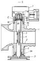
【従来の技術】
従来の吸気制御装置について図3により説明する。1は内部を吸気路2が貫通するスロットルボデーであり、吸気路2を横断するスロットルシャフト3には、吸気路2を開閉するスロットルバルブ4が取着される。スロットルシャフト3はスロットルボデー1のシャフト軸受ボス5に穿設されるシャフトガイド孔6に回動自在に支持されるもので、前記シャフトガイド孔6は吸気路2に対向して形成される。又、シャフト軸受ボス5の一側の先端部5A(図3において上方に示されるシャフト軸受ボス)には、シャフトガイド孔6より大径をなし、吸気路2側(図3において下側)に向かって凹設される有底凹部5Bが形成される。この有底凹部5Bの底面5Cはシャフトガイド孔6の長手軸心線に直交する。
【0003】
Sは開度センサであり、ハウジング7内には摺動子つきのロータ8が回転自在に軸支されるとともに抵抗体パターンを形成した基板がハウジング7の内方に固定配置され、ロータ8の摺動子を抵抗体パターン上に摺動させたもので、ロータ8の下端には、連結用の異形をなす係合孔8Aが下方に向かって穿設される。又、ハウジング7の下端には、下方に向かって突出する筒状のシール筒部7Aが形成される。更に、前記スロットルシャフト3の一端(図3において上方)には、ロータ8の係合孔8Aに係合配置される係合部3Aが形成され、その下方には環状をなす嵌合溝3Bが穿設される。又、スロットルシャフト3の他端(図3において下方)には異形状をなすとともにその外周にオネジ3Cが刻設された取着部3Dが形成される。
【0004】
以上の構成よりなる吸気制御装置は以下によって組付けられる。まず、何等部品の取着されないスロットルシャフト3をシャフトガイド孔6内に挿通配置するもので、このとき、スロットルシャフト3の一端の嵌合溝3Bはシャフト軸受ボス5の先端部5Aより図3において上方に配置される。いいかえると嵌合溝3Bは有底凹部5B内より上方に脱出して配置される。そして、かかる状態にあるスロットルシャフト3の一端より平ワッシャーWをスロットルシャフト3に挿入し、しかる後に嵌合溝3BにEリングEを嵌合配置する。次いで、スロットルシャフト3を自由状態とすると、スロットルシャフト3の一端に配置した平ワッシャーWは有底凹部5Bの底面5CとEリングEとの間に挟持され、図3においてスロットルシャフト3の下方向への移動が抑止され、平ワッシャーWを含むEリングEは、シャフト軸受ボス5の有底凹部5B内に収納配置される。一方、かかる状態においてスロットルシャフト3の他端は、シャフト軸受ボス5の後端部5Dより下方に突出するもので、取着部3Dにワイヤードラム9を挿入配置した後にオネジ3Cにナット10を螺着することによりスロットルシャフト3の他端にワイヤードラム9が螺着配置される。次に吸気路2内にあるスロットルシャフト3にスロットルバルブ4がビス締めされて固着される。そして、更に開度センサSのロータ8の係合孔8Aがスロットルシャフト3の係合部3Aに挿入されて係合され、一方ハウジング7のシール筒部7Aの外周がシャフト軸受ボス5の先端部5Aから有底凹部5B内に挿入配置され、かかる状態において、開度センサSはボルトBによってスロットルボデー1に螺着固定される。
【0005】
そして、運転者が図示せぬアクセルワイヤを介してワイヤードラム9を回転させてスロットルシャフト3を回動させると、スロットルバルブ4は前記回動に応じて吸気路2を開閉制御する。一方スロットルバルブ4の前記開度はスロットルシャフト3の係合部3Aを介してロータ8に同期的に伝達されるものであり、スロットルバルブ4の開度に応じた信号が、開度センサSから出力される。
【0006】
【発明が解決しようとする課題】
かかる従来の吸気制御装置によると以下の不具合を有する。ワイヤードラム9を予めスロットルシャフト3の他端に固着した状態で、スロットルシャフト3の一端に穿設される嵌合溝3B内にEリングEを嵌着できない。これは嵌合溝3Bが有底凹部5B内にあってEリングEの嵌着をさまたげることによる。以上によると、ワイヤードラム9は、EリングEの嵌着後においてスロットルシャフト3の他端にナット10によって螺着される必要があり、これによるとスロットルシャフト3にオネジ3Cを刻設する必要があること。ナット10を用意する必要があること。ナット10の螺着作業を要すること。により部品点数、組付け工数の増加を招来し、製造コストの低減を達成できない。一方、シャフト軸受ボス5の後端部5Dとワイヤードラム9の背面9Aとの距離を大きくとれば、ワイヤードラム9を予めスロットルシャフト3の他端に固着した状態でEリングEを嵌合溝3B内に嵌着可能なものであるが、これによると、スロットルシャフト3の長手方向が大となり、吸気制御装置をコンパクトにまとめることができない。更にスロットルシャフト3のメンテナンス性の向上が阻害される。平ワッシャーWは有底凹部5Bの底面5Cと回動接触するもので、長期に渡る使用時においてその接触部に摩耗粉が発生するが、開度センサSを取外した際において、ワッシャーWが有底凹部5A内に配置されていることからその清掃を容易に行なうことができない。
【0007】
本発明になる吸気制御装置は前記不具合に鑑み成されたもので、部品点数、組付け工数を削減できて製造コストの低減を図るとともにメンテナンス性の向上を達成することのできる開度センサを備える吸気制御装置を提供することを目的とする。
【0008】
【課題を解決する為の手段】
本発明になる吸気制御装置は前記目的達成の為に、スロットルボデーに軸支されたスロットルシャフトの回動に応じて回動するロータを有し、スロットルシャフトに取着されたスロットルバルブの開度を検出する開度センサを備え、
吸気路を横断するスロットルシャフトを有するスロットルボデーには、前記スロットルシャフトを回動自在に軸支するシャフトガイド孔を備えるシャフト軸受ボスが設けられるとともに前記シャフト軸受ボスの平坦状の先端部の外周に、軸方向に沿うガイド筒部が形成され、
スロットルシャフトの一端には、その先端部にロータの係合孔内に係合配置される異形状をなす係合部が形成されるとともにその下方に環状の嵌合溝が形成され、
前記スロットルシャフトを、シャフトガイド孔内に挿入するとともにシャフト軸受ボスの先端部より突出するスロットルシャフトの嵌合溝内にEリングを嵌合配置することにより平ワッシャーを、シャフト軸受ボスの先端部とEリングとの間に挟持し、
前記スロットルシャフトの他端にワイヤードラムをカシメにより固着配置する吸気制御装置において、
開度センサのハウジングには、ロータの外周方向にあってロータの下端より下方に向かって突出する筒状のシール筒部を有し、
スロットルシャフトの係合部をロータの係合孔に係合配置するとともにハウジングのシール筒部をスロットルボデーのガイド筒部に挿入配置し、
更に前記ハウジングには、ハウジングから側方にのび、ボルトによってスロットルボデーに螺着固定される鍔部を有し、
前記鍔部の下面が、前記シール筒部よりも上方に形成されており、前記鍔部の上面に前記ボルトを螺着した時に前記ボルトの頭がハウジングの上面よりも突出することがないように前記鍔部を形成したことを第1の特徴とする。
【0009】
又、本発明は、前記第1の特徴に加え、前記ワイヤードラムが固着されたスロットルシャフトを、シャフト軸受ボスの後端部よりシャフトガイド孔内に向けて挿通し、スロットルシャフトの係合部、嵌合溝をシャフト軸受ボスの先端部より突出配置し、かかる状態においてスロットルシャフトの一端より平ワッシャーをスロットルシャフトに挿入し、次いで嵌合溝にEリングを嵌合配置したことを第2の特徴とする。
【0010】
【作用】
本発明の吸気制御装置の第1の特徴によると、平ワッシャーを含むEリングはシャフト軸受ボスの先端部に配置される。而して平ワッシャーと先端部との間におけるメンテナンス性を向上できるとともにEリングの組付け性の向上とシャフト軸受ボスの加工性を向上できる。
【0011】
又、本発明の第2の特徴によると、スロットルシャフトに予めワイヤードラムを固着配置してシャフトガイド孔に挿入できるので、部品点数の削減、組付け工数の削減を達成できる。
【0012】
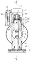
【実施例】
以下、本発明の吸気制御装置の一実施例を図1、図2により説明する。図1はその縦断面図、図2は図1のA−A線における縦断面図、である。尚、図3と同一構造部分は同一符号を使用する。シャフト軸受ボス5の先端部5Aは平坦状に形成され、その外周部分には、スロットルシャフト3の軸方向に沿うガイド筒部5Fが形成される。スロットルシャフト3の一端には、係合部3Aが形成されるとともにその下方には嵌合溝3Bが穿設され、さらに他端にはワイヤードラム9が固着される。本実施例にあってはワイヤードラム9はスロットルシャフト3の他端にカシメ固着された。ワイヤードラム9の固着手段はカシメに限定されるものでなく溶接であってもよい。開度センサSのハウジング7にはロータ8の外周にあって、ロータ8の下端8Bより更に下方に向かって突出する筒状のシール筒部7Aが形成される。
【0013】
次にその組付けについて説明する。ワイヤードラム9が固着されたスロットルシャフト3をシャフト軸受ボス5の後端部5Dよりシャフトガイド孔6内に向けて挿通し、スロットルシャフト3の一端の係合部3A及び嵌合溝3Bをシャフト軸受ボス5の先端部5Aより突出させる。かかる状態において、スロットルシャフト3の一端より平ワッシャーWをスロットルシャフト3に挿入し、しかる後に嵌合溝3BにEリングEを嵌合配置する。以上によると、平ワッシャーWは、シャフト軸受ボス5の先端部5AとEリングEとの間に挟持され、一方スロットルシャフト3の他端に固着配置されるワイヤードラム9はシャフト軸受ボス5の後端部5Dに臨んで配置される。次に吸気路2内にあるスロットルシャフト3に吸気路2を開閉するスロットルバルブ4がネジ締め取着される。次に開度センサSがスロットルボデー1に取着されるもので、ロータ8の嵌合孔8Aにスロットルシャフト3の係合部3Aが挿入配置され、ハウジング7のシール筒部7Aの内方がシャフト軸受ボス5のガイド筒部5Fに挿入配置され、かかる状態においてハウジング7から側方にのびる鍔部7BがボルトBによってスロットルボデー1に螺着固定される。
【0014】
以上よりなる吸気制御装置によると、平ワッシャーW部分のメンテナンス性を大きく向上できる。すなわち、長時間の使用において平ワッシャーWの上下において摺動接触による摩耗粉が発生した際、開度センサSをスロットルボデー1より取外すと、シャフト軸受ボス5の先端部5A、平ワッシャーW、EリングEは完全に外部に突出して露出するもので、例えばエアブローによる洗浄、液体を用いる洗浄に際し、完全に摩耗粉等の異物を除去できる。又、シャフト軸受ボス5の先端部5Aを平坦状に形成することによると、従来の如く有底凹部5Bを形成するものに対し、加工の容易化を図ることができる。又、スロットルシャフト3の一端の嵌合溝3Bをシャフト軸受ボス5の先端部5Aより突出配置したことによると、ワイヤードラム9は予めスロットルシャフト3に固着することができるもので、これによると、従来のスロットルシャフト3へのオネジ3Cの刻設及びナット10が不要となり、更にはナット締め作業が不要となり、部品点数の削減と組付け作業の削減によりその製造コストの低減に効果的である。
【0015】
【発明の効果】
以上の如く、本発明になる開度センサを備える吸気制御装置によると、スロットルシャフトの一端に形成される係合部を含む嵌合溝をシャフト軸受ボスの平坦状をなす先端部より突出させて配置したので、Eリングを嵌合溝に嵌合する作業性を向上できるとともにEリングと先端部間に配置される平ワッシャー部分におけるメンテナンス性の向上を達成できる。又、上記によればワイヤードラムを予めスロットルシャフトの他端に固着配置できるもので、これによるとワイヤードラムをスロットルシャフトへ取着する為のオネジ、ナットが不要となるとともにナット締め作業が不要となり製造コストを低減できたものである。尚、本実施例はスロットルボデーについて説明したが、気化器においても同様に実施できるものである。
【図面の簡単な説明】
【図1】 本発明の吸気制御装置の一実施例を示す縦断面図。
【図2】 図1のA−A線における縦断面図。
【図3】 従来の吸気制御装置を示す縦断面図。
【符号の説明】
1 スロットルボデー
2 吸気路
3 スロットルシャフト
3A 係合部
3B 嵌合溝
5 シャフト軸受ボス
5A 先端部
9 ワイヤードラム
E Eリング
S 開度センサ[0001]
[Industrial application fields]
The present invention relates to an intake control device that controls air or an air-fuel mixture supplied to an internal combustion engine, and more particularly to an intake control device that includes an opening sensor that detects the opening of a throttle valve that controls opening and closing of an intake passage.
[0002]
[Prior art]
A conventional intake control device will be described with reference to FIG.
[0003]
S is an opening sensor, and a
[0004]
The intake control device having the above configuration is assembled as follows. First, the
[0005]
When the driver rotates the
[0006]
[Problems to be solved by the invention]
Such a conventional intake control device has the following problems. In a state where the
[0007]
The intake air control device according to the present invention is made in view of the above problems, and includes an opening sensor that can reduce the number of parts and the number of assembling steps, reduce the manufacturing cost, and improve the maintainability. An object of the present invention is to provide an intake control device.
[0008]
[Means for solving the problems]
In order to achieve the above object, the intake control device according to the present invention has a rotor that rotates in accordance with the rotation of the throttle shaft that is pivotally supported by the throttle body, and the opening of the throttle valve that is attached to the throttle shaft. Equipped with an opening sensor to detect
A throttle body having a throttle shaft that traverses the intake passage is provided with a shaft bearing boss having a shaft guide hole for pivotally supporting the throttle shaft, and on the outer periphery of the flat tip portion of the shaft bearing boss. The guide tube portion along the axial direction is formed,
One end of the throttle shaft is formed with an engaging portion having a different shape that is engaged and disposed in the engaging hole of the rotor at the tip thereof, and an annular fitting groove is formed below the engaging portion.
The throttle shaft is inserted into the shaft guide hole, and the E-ring is fitted and disposed in the fitting groove of the throttle shaft protruding from the tip of the shaft bearing boss, so that the flat washer is connected to the tip of the shaft bearing boss. Sandwiched between E-rings ,
In the air intake control device in which the wire drum is fixed to the other end of the throttle shaft by caulking ,
The housing of the opening sensor has a cylindrical seal tube portion that protrudes downward from the lower end of the rotor in the outer circumferential direction of the rotor,
The engagement portion of the throttle shaft is engaged with the engagement hole of the rotor and the seal cylinder portion of the housing is inserted and arranged in the guide cylinder portion of the throttle body.
Furthermore, the housing has a flange extending laterally from the housing and screwed to the throttle body by a bolt.
The lower surface of the flange portion is formed above the seal cylinder portion so that the bolt head does not protrude beyond the upper surface of the housing when the bolt is screwed onto the upper surface of the flange portion. The first feature is that the collar is formed .
[0009]
According to the present invention, in addition to the first feature, the throttle shaft to which the wire drum is fixed is inserted from the rear end portion of the shaft bearing boss into the shaft guide hole. A second feature is that the fitting groove is projected from the tip of the shaft bearing boss, and in this state, a flat washer is inserted into the throttle shaft from one end of the throttle shaft, and then an E-ring is fitted and arranged in the fitting groove. And
[0010]
[Action]
According to the first feature of the intake control device of the present invention, the E-ring including the flat washer is disposed at the tip of the shaft bearing boss. Thus, the maintainability between the flat washer and the tip can be improved, and the assembly of the E-ring can be improved and the workability of the shaft bearing boss can be improved.
[0011]
Further, according to the second aspect of the present invention, Runode be inserted by fixing arranged beforehand wire drum to the throttle shaft into the shaft guide holes, reducing the number of parts, reduction of assembling steps can be achieved.
[0012]
【Example】
An embodiment of an intake air control apparatus according to the present invention will be described below with reference to FIGS. 1 is a longitudinal sectional view thereof, and FIG. 2 is a longitudinal sectional view taken along line AA of FIG. In addition, the same code | symbol is used for the same structure part as FIG. The
[0013]
Next, the assembly will be described. The
[0014]
According to the intake control device configured as described above, the maintainability of the flat washer W portion can be greatly improved. That is, when wear powder due to sliding contact is generated above and below the flat washer W during long-term use, if the opening sensor S is removed from the
[0015]
【The invention's effect】
As described above, according to the intake control device including the opening sensor according to the present invention, the fitting groove including the engaging portion formed at one end of the throttle shaft is protruded from the flat tip end portion of the shaft bearing boss. Since it arrange | positioned, the workability | operativity which fits an E ring in a fitting groove can be improved, and the improvement of the maintainability in the flat washer part arrange | positioned between an E ring and a front-end | tip part can be achieved. In addition, according to the above, the wire drum can be fixedly disposed on the other end of the throttle shaft in advance, which eliminates the need for male screws and nuts for attaching the wire drum to the throttle shaft and eliminates the need for nut tightening work. The manufacturing cost can be reduced. Although the present embodiment has been described with respect to the throttle body, the same can be applied to the carburetor.
[Brief description of the drawings]
FIG. 1 is a longitudinal sectional view showing an embodiment of an intake control device of the present invention.
FIG. 2 is a longitudinal sectional view taken along line AA in FIG.
FIG. 3 is a longitudinal sectional view showing a conventional intake control device.
[Explanation of symbols]
DESCRIPTION OF
Claims (2)
吸気路(2)を横断するスロットルシャフト(3)を有するスロットルボデー(1)には、前記スロットルシャフトを回動自在に軸支するシャフトガイド孔(6)を備えるシャフト軸受ボス(5)が設けられるとともに前記シャフト軸受ボスの平坦状の先端部(5A)の外周に、軸方向に沿うガイド筒部(5F)が形成され、
スロットルシャフト(3)の一端には、その先端部にロータ(8)の係合孔(8A)内に係合配置される異形状をなす係合部(3A)が形成されるとともにその下方に環状の嵌合溝(3B)が形成され、
前記スロットルシャフトを、シャフトガイド孔(6)内に挿入するとともにシャフト軸受ボス(5)の先端部(5A)より突出するスロットルシャフト(3)の嵌合溝(3B)内にEリング(E)を嵌合配置することにより平ワッシャー(W)を、シャフト軸受ボス(5)の先端部(5A)とEリング(E)との間に挟持し、
前記スロットルシャフトの他端にワイヤードラム(9)をカシメにより固着配置する吸気制御装置において、
開度センサ(S)のハウジング(7)には、ロータ(8)の外周方向にあってロータ(8)の下端(8B)より下方に向かって突出する筒状のシール筒部(7A)を有し、
スロットルシャフト(3)の係合部(3A)をロータ(8)の係合孔(8A)に係合配置するとともにハウジング(7)のシール筒部(7A)をスロットルボデー(1)のガイド筒部(5F)に挿入配置し、
更に前記ハウジングには、ハウジング(7)から側方にのび、ボルト(B)によってスロットルボデー(1)に螺着固定される鍔部(7B)を有し、
前記鍔部(7B)の下面が、前記シール筒部(7A)よりも上方に形成されており、前記鍔部(7B)の上面に前記ボルト(B)を螺着した時に前記ボルト(B)の頭がハウジングの上面よりも突出することがないように前記鍔部(7B)を形成したことを特徴とする吸気制御装置。A rotor that rotates according to the rotation of the throttle shaft pivotally supported by the throttle body, and an opening sensor that detects the opening of the throttle valve attached to the throttle shaft;
A throttle body (1) having a throttle shaft (3) traversing the intake passage (2) is provided with a shaft bearing boss (5) having a shaft guide hole (6) for pivotally supporting the throttle shaft. And a guide tube portion (5F) along the axial direction is formed on the outer periphery of the flat tip portion (5A) of the shaft bearing boss,
At one end of the throttle shaft (3), an engaging portion (3A) having a different shape is formed at the tip of the throttle shaft (3A) and engaged with the engaging hole (8A) of the rotor (8). An annular fitting groove (3B) is formed,
The E-ring (E) is inserted into the fitting groove (3B) of the throttle shaft (3) which is inserted into the shaft guide hole (6) and protrudes from the tip (5A) of the shaft bearing boss (5). The flat washer (W) is sandwiched between the tip end (5A) of the shaft bearing boss (5) and the E ring (E)
In the air intake control device in which the wire drum (9) is fixed to the other end of the throttle shaft by caulking ,
The housing (7) of the opening sensor (S) has a cylindrical seal cylinder (7A) that protrudes downward from the lower end (8B) of the rotor (8) in the outer circumferential direction of the rotor (8). Have
The engaging portion (3A) of the throttle shaft (3) is engaged with the engaging hole (8A) of the rotor (8), and the seal tube portion (7A) of the housing (7) is inserted into the guide tube of the throttle body (1). Inserted into the section (5F),
Furthermore, the housing has a flange portion (7B) extending from the housing (7) to the side and screwed to the throttle body (1) by a bolt (B).
The lower surface of the flange portion (7B) is formed above the seal tube portion (7A), and the bolt (B) is screwed when the bolt (B) is screwed onto the upper surface of the flange portion (7B). The intake control device is characterized in that the flange portion (7B) is formed so that the head of the housing does not protrude from the upper surface of the housing .
Priority Applications (4)
| Application Number | Priority Date | Filing Date | Title |
|---|---|---|---|
| JP2001031286A JP4088745B2 (en) | 2001-02-07 | 2001-02-07 | Intake control device |
| CN 01139825 CN1246579C (en) | 2001-02-07 | 2001-11-30 | Suction control device |
| TW90130542A TW534948B (en) | 2001-02-07 | 2001-12-10 | Intake controller |
| HK03101031.6A HK1048839B (en) | 2001-02-07 | 2003-02-13 | An intake air control apparatus |
Applications Claiming Priority (1)
| Application Number | Priority Date | Filing Date | Title |
|---|---|---|---|
| JP2001031286A JP4088745B2 (en) | 2001-02-07 | 2001-02-07 | Intake control device |
Publications (2)
| Publication Number | Publication Date |
|---|---|
| JP2002235560A JP2002235560A (en) | 2002-08-23 |
| JP4088745B2 true JP4088745B2 (en) | 2008-05-21 |
Family
ID=18895392
Family Applications (1)
| Application Number | Title | Priority Date | Filing Date |
|---|---|---|---|
| JP2001031286A Expired - Lifetime JP4088745B2 (en) | 2001-02-07 | 2001-02-07 | Intake control device |
Country Status (4)
| Country | Link |
|---|---|
| JP (1) | JP4088745B2 (en) |
| CN (1) | CN1246579C (en) |
| HK (1) | HK1048839B (en) |
| TW (1) | TW534948B (en) |
Families Citing this family (3)
| Publication number | Priority date | Publication date | Assignee | Title |
|---|---|---|---|---|
| ES2309702T3 (en) * | 2005-05-11 | 2008-12-16 | Magneti Marelli Powertrain S.P.A. | A TORBELLINO SYSTEM FOR THE ADMINSION COLLECTOR OF AN INTERNAL COMBUSTION ENGINE WITH AN ACTUATOR MADE WITH A FORMAT MEMORY MATERIAL. |
| JP5810809B2 (en) * | 2011-10-04 | 2015-11-11 | 株式会社デンソー | Intake device for internal combustion engine |
| JP6202530B2 (en) * | 2014-03-12 | 2017-09-27 | 株式会社ケーヒン | Engine intake air amount control device |
-
2001
- 2001-02-07 JP JP2001031286A patent/JP4088745B2/en not_active Expired - Lifetime
- 2001-11-30 CN CN 01139825 patent/CN1246579C/en not_active Expired - Lifetime
- 2001-12-10 TW TW90130542A patent/TW534948B/en not_active IP Right Cessation
-
2003
- 2003-02-13 HK HK03101031.6A patent/HK1048839B/en not_active IP Right Cessation
Also Published As
| Publication number | Publication date |
|---|---|
| JP2002235560A (en) | 2002-08-23 |
| HK1048839B (en) | 2006-06-23 |
| HK1048839A1 (en) | 2003-04-17 |
| CN1246579C (en) | 2006-03-22 |
| TW534948B (en) | 2003-06-01 |
| CN1368596A (en) | 2002-09-11 |
Similar Documents
| Publication | Publication Date | Title |
|---|---|---|
| JP4088745B2 (en) | Intake control device | |
| US6581569B2 (en) | Valve control unit for an internal combustion engine | |
| US7111609B2 (en) | Intake air control device having strain absorbing structure | |
| JP2006002607A (en) | Variable valve gear for internal combustion engine and method for assembling the variable valve gear | |
| JPH1089427A (en) | Lever arm for auto tensioner | |
| JP2004162680A (en) | Electric type throttle body | |
| JP2004132234A (en) | Throttle control device | |
| JPH0511419Y2 (en) | ||
| US20030094038A1 (en) | Throttle valve adjustment unit | |
| JP4384777B2 (en) | Engine intake control system | |
| JPH063147Y2 (en) | Intake control valve device for internal combustion engine | |
| JP3673064B2 (en) | Shaft coupling structure of inhibitor switch | |
| JP3600005B2 (en) | Throttle valve position detector | |
| JPS6036502Y2 (en) | Sealing device in automobile wiper | |
| JP2003065444A (en) | Oil seal attaching structure | |
| JP2025039416A (en) | Throttle valve control device | |
| JPH0129342Y2 (en) | ||
| JPH0238046Y2 (en) | ||
| JPH0341071Y2 (en) | ||
| JP2524489Y2 (en) | Engagement structure between throttle valve lever and actuator operating member | |
| JP3676563B2 (en) | Sensor support structure in engine | |
| JPH10252505A (en) | Link structure of multiple throttle valve | |
| JP2023042089A (en) | Throttle device | |
| JPH0514542U (en) | Throttle valve opening control device | |
| JPH04287842A (en) | Throttle valve opening detecting device for internal combustion engine |
Legal Events
| Date | Code | Title | Description |
|---|---|---|---|
| A621 | Written request for application examination |
Free format text: JAPANESE INTERMEDIATE CODE: A621 Effective date: 20040512 |
|
| A977 | Report on retrieval |
Free format text: JAPANESE INTERMEDIATE CODE: A971007 Effective date: 20061208 |
|
| A131 | Notification of reasons for refusal |
Free format text: JAPANESE INTERMEDIATE CODE: A131 Effective date: 20061219 |
|
| A521 | Written amendment |
Free format text: JAPANESE INTERMEDIATE CODE: A523 Effective date: 20070206 |
|
| A02 | Decision of refusal |
Free format text: JAPANESE INTERMEDIATE CODE: A02 Effective date: 20070529 |
|
| A521 | Written amendment |
Free format text: JAPANESE INTERMEDIATE CODE: A523 Effective date: 20070725 |
|
| A911 | Transfer to examiner for re-examination before appeal (zenchi) |
Free format text: JAPANESE INTERMEDIATE CODE: A911 Effective date: 20071107 |
|
| TRDD | Decision of grant or rejection written | ||
| A01 | Written decision to grant a patent or to grant a registration (utility model) |
Free format text: JAPANESE INTERMEDIATE CODE: A01 Effective date: 20071218 |
|
| R155 | Notification before disposition of declining of application |
Free format text: JAPANESE INTERMEDIATE CODE: R155 |
|
| A61 | First payment of annual fees (during grant procedure) |
Free format text: JAPANESE INTERMEDIATE CODE: A61 Effective date: 20080212 |
|
| R150 | Certificate of patent or registration of utility model |
Free format text: JAPANESE INTERMEDIATE CODE: R150 Ref document number: 4088745 Country of ref document: JP Free format text: JAPANESE INTERMEDIATE CODE: R150 |
|
| FPAY | Renewal fee payment (event date is renewal date of database) |
Free format text: PAYMENT UNTIL: 20110307 Year of fee payment: 3 |
|
| FPAY | Renewal fee payment (event date is renewal date of database) |
Free format text: PAYMENT UNTIL: 20110307 Year of fee payment: 3 |
|
| FPAY | Renewal fee payment (event date is renewal date of database) |
Free format text: PAYMENT UNTIL: 20120307 Year of fee payment: 4 |
|
| R250 | Receipt of annual fees |
Free format text: JAPANESE INTERMEDIATE CODE: R250 |
|
| FPAY | Renewal fee payment (event date is renewal date of database) |
Free format text: PAYMENT UNTIL: 20120307 Year of fee payment: 4 |
|
| FPAY | Renewal fee payment (event date is renewal date of database) |
Free format text: PAYMENT UNTIL: 20130307 Year of fee payment: 5 |
|
| R250 | Receipt of annual fees |
Free format text: JAPANESE INTERMEDIATE CODE: R250 |
|
| FPAY | Renewal fee payment (event date is renewal date of database) |
Free format text: PAYMENT UNTIL: 20130307 Year of fee payment: 5 |
|
| FPAY | Renewal fee payment (event date is renewal date of database) |
Free format text: PAYMENT UNTIL: 20140307 Year of fee payment: 6 |
|
| R250 | Receipt of annual fees |
Free format text: JAPANESE INTERMEDIATE CODE: R250 |
|
| R250 | Receipt of annual fees |
Free format text: JAPANESE INTERMEDIATE CODE: R250 |
|
| R250 | Receipt of annual fees |
Free format text: JAPANESE INTERMEDIATE CODE: R250 |
|
| R250 | Receipt of annual fees |
Free format text: JAPANESE INTERMEDIATE CODE: R250 |
|
| R250 | Receipt of annual fees |
Free format text: JAPANESE INTERMEDIATE CODE: R250 |
|
| R250 | Receipt of annual fees |
Free format text: JAPANESE INTERMEDIATE CODE: R250 |
|
| R250 | Receipt of annual fees |
Free format text: JAPANESE INTERMEDIATE CODE: R250 |
|
| R250 | Receipt of annual fees |
Free format text: JAPANESE INTERMEDIATE CODE: R250 |
|
| EXPY | Cancellation because of completion of term |