JP4088733B2 - Reinforcing bar receiver - Google Patents
Reinforcing bar receiver Download PDFInfo
- Publication number
- JP4088733B2 JP4088733B2 JP03148499A JP3148499A JP4088733B2 JP 4088733 B2 JP4088733 B2 JP 4088733B2 JP 03148499 A JP03148499 A JP 03148499A JP 3148499 A JP3148499 A JP 3148499A JP 4088733 B2 JP4088733 B2 JP 4088733B2
- Authority
- JP
- Japan
- Prior art keywords
- reinforcing bar
- metal wire
- planar portions
- rebar
- adjacent
- Prior art date
- Legal status (The legal status is an assumption and is not a legal conclusion. Google has not performed a legal analysis and makes no representation as to the accuracy of the status listed.)
- Expired - Lifetime
Links
- 230000003014 reinforcing effect Effects 0.000 title claims description 55
- 239000002184 metal Substances 0.000 claims description 30
- 238000004804 winding Methods 0.000 claims description 26
- 238000005452 bending Methods 0.000 claims description 8
- 230000008878 coupling Effects 0.000 claims description 7
- 238000010168 coupling process Methods 0.000 claims description 7
- 238000005859 coupling reaction Methods 0.000 claims description 7
- 239000000463 material Substances 0.000 description 4
- 238000010276 construction Methods 0.000 description 3
- 230000000694 effects Effects 0.000 description 2
- 229910000831 Steel Inorganic materials 0.000 description 1
- 238000010586 diagram Methods 0.000 description 1
- 238000009434 installation Methods 0.000 description 1
- 239000010959 steel Substances 0.000 description 1
Images
Landscapes
- Reinforcement Elements For Buildings (AREA)
Description
【0001】
【発明の属する技術分野】
本発明は鉄筋受け、詳しくは一本の金属線材の屈曲加工より形成した鉄筋受けに関する。
【0002】
【従来技術】
従来、鉄筋受けとしてプラスチック製、コンクリート製及び金属製等、材質,形状等を異にする種々の構成のものが提案されているが、特に一本の金属線材から屈曲形成された鉄筋受けは、構造簡素にして使用取り扱いやすい、安価である、コンクリート打設時に受ける流動抵抗が小さく設置位置を安定確実に保持できる、コンクリートの流動を妨げないのでコンクリート中に巣を発生させることがない、等の理由で、広く一般に普及している。
【0003】
【発明が解決しようとする課題】
一本の金属線材を屈曲加工して鉄筋受けを形成する場合、自立性を得るために2本の足部付き脚杆部を形成しなければならず、また鉄筋をしっかりと嵌め込み固定するためにU字状の鉄筋受架部を屈曲形成しなければならない等の理由のためにどうしても形状的に大きくなり嵩張り、輸送、保管に場所をとるばかりでなく、配筋作業時の使用取り扱いにも不便であった。またコンクリートのかぶり厚さは施工現場やコンクリート構造物のグレード等によって異なり、通常はかぶり厚さごとに高さの異なる数種類の鉄筋受けが製造され準備されるが、これでは在庫管理に不便であるばかりでなく在庫量が増え、かぶり厚さの寸法差に対応できる構成のものが望まれていた。また配筋される鉄筋の太さにも施工現場やコンクリート構造物のグレード等により寸法差があり、この場合も、寸法差に対応できれば便利である。
【0004】
本発明の目的は、コンパクト構造にして、しかも価格及び品質,性能のいずれをも満足し得る金属線材製の鉄筋受けを提供するにある。
【0005】
さらに、本発明の目的は、コンパクト構造にしてしかも価格及び品質,性能のいずれもを満足し得る上にコンクリートの被り厚さの寸法差にも対応できる金属線材製の鉄筋受けを提供するにある。
【0006】
さらに、本発明の目的は、コンパクト構造にしてしかも価格及び品質,性能のいずれもを満足し得る上に鉄筋の太さの寸法差にも対応できる金属線材製の鉄筋受けを提供するにある。
【0007】
【課題を解決するための手段】
本発明は、一本の金属線材を屈曲加工して形成した鉄筋受けであって、自立性を付与するための足部を備え、上下方向に延びる離間した2本の脚杆部と、該脚杆部の上端間を連成する螺旋巻回部とを備え、該螺旋巻回部は、平行に並ぶ異なる仮想平面に沿って前記金属線材が巻回することで形成される少なくとも2つの平面状部を備え、隣り合う2つの該平面状部と、該隣り合う2つの平面状部に連続する金属線材とによって、前記仮想平面に平行な方向から見て正面U溝状の鉄筋受架部を構成し、該受架部内の前記隣り合う2つの平面状部の間に鉄筋を摩擦嵌合状態に嵌め込むことができる構成になっていることを特徴とする鉄筋受けに係る(以下、第1発明という)。
【0008】
更に本発明は、一本の金属線材を屈曲加工して形成した鉄筋受けであって、自立性を付与するための足部を備え、上下方向に延びる離間した2本の脚杆部と、該脚杆部の上端間を連成する螺旋巻回部とを備え、該螺旋巻回部は、平行に並ぶ異なる仮想平面に沿って前記金属線材が巻回することで形成される少なくとも3つの平面状部を備え、隣り合う2つの該平面状部と、該隣り合う2つの平面状部に連続する金属線材とによって、前記仮想平面に平行な方向から見て複数個且つ高さを異にする正面U溝状の鉄筋受架部を構成し、選択された1つの上記受架部内の前記隣り合う2つの平面状部の間に鉄筋を摩擦嵌合状態に嵌め込むことができる構成になっていることを特徴とする鉄筋受けに係る(以下、第2発明という)。
【0009】
更に本発明は、一本の金属線材を屈曲加工して構成した鉄筋受けであって、自立性を付与するための足部を備え、上下方向に延びる離間した2本の脚杆部と、該脚杆部の上端間を連成する螺旋巻回部とを備え、該螺旋巻回部は、平行に並ぶ異なる仮想平面に沿って前記金属線材が巻回することで形成される少なくとも3つの平面状部を備え、隣り合う2つの該平面状部と、該隣り合う2つの平面状部に連続する金属線材とによって、前記仮想平面に平行な方向から見て複数個且つ溝幅を大小異にする正面U溝状の鉄筋受架部を構成し、選択された1つの上記受架部内の前記隣り合う2つの平面状部の間に鉄筋を摩擦嵌合状態に嵌め込むことができる構成になっていることを特徴とする鉄筋受けに係る(以下、第3発明という)。
【0010】
【発明の実施の形態】
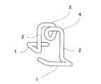
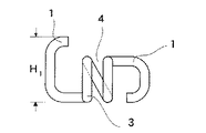
以下に、本発明の一実施形態を添付図面に基づき説明する。図1乃至図5は本発明の第1発明の一実施形態を示し、一本の鉄筋a(図2参照)を所定高さに支持し得る構成になっている。以下、第1発明に付き詳細に説明する。図1から明らかなように、第1発明の鉄筋受けは、一本の金属線材(例えば鋼鉄線材)の屈曲加工構造を有し、下端に足部1が屈曲形成された左右一対の脚杆部2、2を備え、該脚杆部2,2の上端は、図1に示すように、螺旋巻回部3を介し連成されている。尚、図1〜5では脚杆部2,2を螺旋巻回部3の一端側と他端側とに前後に位置をずらせて連成した場合が示されているが、螺旋巻回部3を半ピッチ延長させ、前後のいずれか一方側に揃えるようにしてもよい。
【0011】
足部1は鉄筋受けに自立性を付与するためのもであり、図1〜5では脚杆部2,2の下端部に、螺旋巻回部3を挟んで向き合うように、平面コ字型の足部1,1を屈曲形成した構成のものが示されているが、その平面形状は自立性が得られるものであれば特に制限されず、平面L型、山形等任意である。尚、足部1の前後方向の幅H1(図5参照)は螺旋巻回部3の巻回外径の範囲内にほぼ収まっていることが好ましいが、巻回外径が比較的小さい場合には、自立性向上を目的として、図示のように、少なくとも一方側の足部1を巻回外径を超えて、外側方へ若干はみ出すように形成してもよい。
【0012】
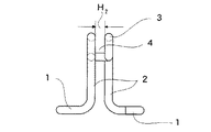
螺旋巻回部3には、図3,5に示すように、螺旋巻回に基づき一つの正面U溝状の鉄筋受架部4が形成され、該受架部4の溝幅H2は鉄筋aの直径と略々等しいか或いはこれより若干小さく、鉄筋aを摩擦嵌合状態に嵌め込むことができる構成になっている。鉄筋受架部4はこれを構成している金属線材の保有弾性に抗し多少は押し開くことができ、少し太めの鉄筋であっても保有弾性を利用して無理に押し入れ嵌め込むことができる。
【0013】
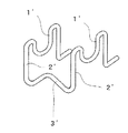
従来提供されているこの種鉄筋受けの代表的な例の一つとして、図16に示すような構成のものを上げることができる。この場合、鉄筋受架部1′を、例えばU字状に形成すれば、鉄筋を該受架部1′内に摩擦嵌合状態に嵌め込むことができるが、従来構成のものでは、前後一対の門型部2′を構成要素として含み、且つ自立性を得るために門型部2′,2′間にかなりの間隔をあけて連成部3′を形成することが必要になり、形状的に大きくなり嵩張るという問題点がある。 第1発明によれば、螺旋巻回により正面U溝状の鉄筋受架部4を形成する構成になっているので、形状的にコンパクトとなり小型で嵩小となり、輸送保管に場所をとらず便利である上、配筋作業時等の使用取り扱いも容易になる。
【0014】
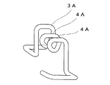
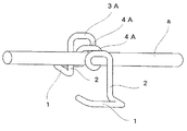
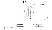
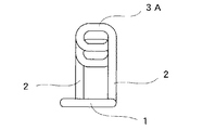
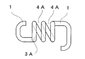
図6乃至10図は本発明の第2発明の一実施形態を示し、第2発明は螺旋巻回部3Aに、複数個、例えば2個のU溝状の鉄筋受架部4Aと、これら2個の鉄筋受架部4A、4A間に高低差を付けたことを特徴とし、これ以外の構成は図1乃至図5に示す第1発明と実質的に異なるところがない。
【0015】
第2発明によれば、高低差のある2つの鉄筋受架部4A,4Aを備えているので、その内の1つを選択的に使用することにより、鉄筋aの支持高さひいてはコンクリートのかぶり厚さを変更でき、一種の鉄筋受けを鉄筋支持高さひいてはコンクリートのかぶり厚さを異にする、2つの施工現場に適用できる。
【0016】
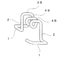
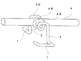
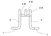
図11乃至図15は本発明の第3発明の一実施形態を示し、第3発明は螺旋巻回部3Bに、複数個、例えば2個のU溝状の鉄筋受架部4B,4Bを溝幅を異ならせて同一高さに形成したことを特徴とし、これ以外の構成は第1発明と実質的に異なるところがない。
【0017】
第3発明によれば、溝幅を相違する2つの鉄筋受架部4B,4Bを備えているので、その内の1つを選択的に使用することにより、鉄筋aとして太さの異なる2種の鉄筋に適用することが可能になり、鉄筋受けを太さを異にする2種の鉄筋に適用することが可能になる。
【0018】
第3発明に於いて、鉄筋受架部4B,4Bに高低差を付けるようにすれば第2発明と同様の効果が追加的に得られる。
【0019】
【発明の効果】
本発明の第1発明によれば、コンパクト構造にして、しかも価格及び品質,性能のいずれをも満足し得る金属線材製の鉄筋受けを提供できる。
【0020】
更に、本発明の第2発明によれば、コンパクト構造にしてしかも価格及び品質,性能のいずれもを満足し得る上にコンクリートの被り厚さの寸法差にも対応できる金属線材製の鉄筋受けを提供できる。
【0021】
更に、本発明の第3発明によれば、コンパクト構造にしてしかも価格及び品質,性能のいずれもを満足し得る上に鉄筋の太さの寸法差にも対応できる金属線材製の鉄筋受けを提供できる。
【図面の簡単な説明】
【図1】本発明の第1発明の一実施形態を示す斜視図である。
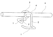
【図2】同、使用状況を示す斜視図である。
【図3】図1に示す鉄筋受けの正面図である。
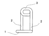
【図4】同、側面図である。
【図5】同、平面図である。
【図6】本発明の第2発明の一実施形態を示す斜視図である。
【図7】同、一使用状況を示す斜視図である。
【図8】図6に示す鉄筋受けの正面図である。
【図9】同、側面図である。
【図10】同、平面図である。
【図11】本発明の第3発明の一実施形態を示す斜視図である。
【図12】同、一使用状況を示す斜視図である。
【図13】図11に示す鉄筋受けの正面図である。
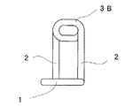
【図14】同、側面図である。
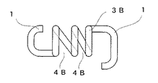
【図15】同、平面図である。
【図16】本発明を説明するための参考図である。
【符号の説明】
1 足部
2 脚杆部
3 螺旋巻回部
4 鉄筋受架部[0001]
BACKGROUND OF THE INVENTION
The present invention relates to a reinforcing bar receiver, and more particularly to a reinforcing bar receiver formed by bending a single metal wire.
[0002]
[Prior art]
Conventionally, various configurations of different materials, shapes, etc., such as plastic, concrete and metal, have been proposed as reinforcing bar receivers, but in particular, reinforcing bar receivers that are bent from a single metal wire, Simple structure, easy to use, inexpensive, low flow resistance when placing concrete, stable installation position can be maintained stably, no hindrance in concrete because it does not hinder the flow of concrete, etc. For this reason, it is widely used.
[0003]
[Problems to be solved by the invention]
When bending a single metal wire to form a reinforcing bar support, you must form two leg collars with legs in order to gain independence, and to securely fit and fix the reinforcing bars The U-shaped rebar support part must be bent and formed, so it is inevitably large and bulky, not only takes up space for transportation and storage, but also for handling during bar arrangement work. It was inconvenient. In addition, the concrete cover thickness varies depending on the construction site and the grade of the concrete structure. Usually, several types of reinforcing bar receivers with different heights are manufactured and prepared for each cover thickness, but this is inconvenient for inventory management. In addition to the increase in the amount of stock, a configuration that can cope with the dimensional difference in the cover thickness has been desired. In addition, there is a dimensional difference in the thickness of the reinforcing bars to be arranged depending on the construction site and the grade of the concrete structure. In this case, it is convenient if the dimensional difference can be accommodated.
[0004]
An object of the present invention is to provide a reinforcing bar receiver made of a metal wire that has a compact structure and can satisfy all of price, quality, and performance.
[0005]
It is another object of the present invention to provide a metal wire rod reinforcing bar receiver that has a compact structure, can satisfy all of the cost, quality, and performance, and can cope with a difference in the thickness of the concrete covering. .
[0006]
Furthermore, an object of the present invention is to provide a reinforcing bar receiver made of a metal wire material that has a compact structure and can satisfy all of the price, quality, and performance, and that can cope with a dimensional difference in the thickness of the reinforcing bar.
[0007]
[Means for Solving the Problems]
The present invention relates to a reinforcing bar receiver formed by bending a single metal wire , which includes a leg portion for providing independence, and two spaced leg legs extending in the vertical direction, and the leg. and a helical winding unit for coupling the upper ends of the rod portions, said helically wound portion is at least two planar to the metal wire along a different virtual planes aligned parallel is formed by winding A front U-groove reinforcing bar receiving portion as viewed from a direction parallel to the virtual plane by two adjacent planar portions and a metal wire continuous to the two adjacent planar portions. configured, according to the receiving rebar, characterized in that has a structure which can be fitted to the friction fit state rebar between the two planar portion adjacent the receiving rack portion (hereinafter, first Called invention).
[0008]
Furthermore, the present invention is a reinforcing bar receiver formed by bending a single metal wire, comprising leg portions for imparting independence, and two spaced leg portions extending in the vertical direction, and a helical winding unit for coupling the upper ends of the legs rod portion, the helical winding unit has at least three planes in which the metal wire along a different virtual planes aligned parallel is formed by winding comprising a Jo portion, and two flat planar portion adjacent, by the metal wire that is continuous with the two planar portions mutually Ri該隣, to different multiple and height as viewed in a direction parallel to the virtual plane It constitutes a front U-groove-shaped reinforcing bar receiving part, and the reinforcing bar can be fitted in a friction fitting state between the two adjacent planar parts in one selected receiving part. (Hereinafter referred to as the second invention).
[0009]
Furthermore, the present invention is a reinforcing bar receiver formed by bending a single metal wire, and includes two legs that are provided with a foot portion for providing independence, and that are spaced apart from each other and extending in the vertical direction. and a helical winding unit for coupling the upper ends of the legs rod portion, the helical winding unit has at least three planes in which the metal wire along a different virtual planes aligned parallel is formed by winding A plurality of adjacent planar members and a metal wire continuous to the two adjacent planar members, and a plurality of groove widths are made different in size from the direction parallel to the virtual plane. The front U-groove reinforcing bar receiving portion is configured such that the reinforcing bar can be fitted in a friction fitting state between the two adjacent planar portions in the selected one receiving portion. The present invention relates to a reinforcing bar receiver (hereinafter referred to as a third invention).
[0010]
DETAILED DESCRIPTION OF THE INVENTION
Hereinafter, an embodiment of the present invention will be described with reference to the accompanying drawings. 1 to 5 show an embodiment of the first invention of the present invention, which is configured to support a single reinforcing bar a (see FIG. 2) at a predetermined height. Hereinafter, the first invention will be described in detail. As is clear from FIG. 1, the reinforcing bar receiver of the first invention has a bent structure of a single metal wire (for example, a steel wire), and a pair of left and right leg portions with a
[0011]
The
[0012]
As shown in FIGS. 3 and 5, the
[0013]
As a typical example of this kind of reinforcing bar receiver provided conventionally, a structure as shown in FIG. 16 can be raised. In this case, if the reinforcing
[0014]
6 to 10 show an embodiment of the second invention of the present invention. In the second invention, a plurality of, for example, two U-groove rebar support portions 4A and two of these are provided in the
[0015]
According to the second invention, since the two reinforcing bar support portions 4A and 4A having a difference in height are provided, by selectively using one of them, the supporting height of the reinforcing bar a and thus the cover of the concrete is provided. The thickness can be changed, and it can be applied to two construction sites where a kind of reinforcing bar support is different from the reinforcing bar support height and the concrete cover thickness.
[0016]
11 to 15 show an embodiment of the third invention of the present invention. In the third invention, a plurality of, for example, two U-groove reinforcing bar support portions 4B and 4B are provided in the spirally wound portion 3B. It is characterized in that it is formed to have the same height with different widths, and other configurations are not substantially different from the first invention.
[0017]
According to the third invention, since the two reinforcing bar support portions 4B and 4B having different groove widths are provided, by selectively using one of them, two types having different thicknesses as the reinforcing bar a It becomes possible to apply to two types of reinforcing bars having different thicknesses.
[0018]
In the third aspect of the invention, the same effect as that of the second aspect of the invention can be additionally obtained by providing a height difference between the reinforcing bar support portions 4B and 4B.
[0019]
【The invention's effect】
According to the first invention of the present invention, it is possible to provide a reinforcing bar receiver made of a metal wire that has a compact structure and can satisfy all of price, quality, and performance.
[0020]
Furthermore, according to the second invention of the present invention, there is provided a reinforcing bar receiver made of a metal wire material that is compact in structure and can satisfy all of the price, quality, and performance, and that can also cope with a dimensional difference in concrete covering thickness. Can be provided.
[0021]
Furthermore, according to the third aspect of the present invention, there is provided a reinforcing bar receiver made of a metal wire material that can satisfy a price, quality, and performance, and can cope with a dimensional difference in the thickness of the reinforcing bar. it can.
[Brief description of the drawings]
FIG. 1 is a perspective view showing an embodiment of the first invention of the present invention.
FIG. 2 is a perspective view showing a use situation.
3 is a front view of the reinforcing bar receiver shown in FIG. 1. FIG.
FIG. 4 is a side view of the same.
FIG. 5 is a plan view of the same.
FIG. 6 is a perspective view showing an embodiment of the second invention of the present invention.
FIG. 7 is a perspective view showing one use situation.
FIG. 8 is a front view of the reinforcing bar receiver shown in FIG. 6;
FIG. 9 is a side view of the same.
FIG. 10 is a plan view of the same.
FIG. 11 is a perspective view showing an embodiment of the third invention of the present invention.
FIG. 12 is a perspective view showing one use situation.
13 is a front view of the reinforcing bar receiver shown in FIG.
FIG. 14 is a side view of the same.
FIG. 15 is a plan view of the same.
FIG. 16 is a reference diagram for explaining the present invention.
[Explanation of symbols]
1
Claims (3)
自立性を付与するための足部を備え、上下方向に延びる離間した2本の脚杆部と、
該脚杆部の上端間を連成する螺旋巻回部とを備え、
該螺旋巻回部は、平行に並ぶ異なる仮想平面に沿って前記金属線材が巻回することで形成される少なくとも2つの平面状部を備え、隣り合う2つの該平面状部と、該隣り合う2つの平面状部に連続する金属線材とによって、前記仮想平面に平行な方向から見て正面U溝状の鉄筋受架部を構成し、該受架部内の前記隣り合う2つの平面状部の間に鉄筋を摩擦嵌合状態に嵌め込むことができる構成になっていることを特徴とする鉄筋受け。A rebar receiver formed by bending a single metal wire,
Two legs that are provided with foot portions for providing independence and that extend in the vertical direction ;
And a helical winding unit for coupling the upper ends of the leg rod portion,
The spiral winding portion includes at least two planar portions formed by winding the metal wire along different virtual planes arranged in parallel, and the two adjacent planar portions and the adjacent ones A front U-groove-shaped reinforcing bar receiving portion as viewed from a direction parallel to the virtual plane is constituted by a metal wire continuous to two planar portions, and the two adjacent planar portions in the receiving portion receiving rebar, characterized in that has a structure that can fit the rebar friction fit state between.
自立性を付与するための足部を備え、上下方向に延びる離間した2本の脚杆部と、
該脚杆部の上端間を連成する螺旋巻回部とを備え、
該螺旋巻回部は、平行に並ぶ異なる仮想平面に沿って前記金属線材が巻回することで形成される少なくとも3つの平面状部を備え、隣り合う2つの該平面状部と、該隣り合う2つの平面状部に連続する金属線材とによって、前記仮想平面に平行な方向から見て複数個且つ高さを異にする正面U溝状の鉄筋受架部を構成し、選択された1つの上記受架部内の前記隣り合う2つの平面状部の間に鉄筋を摩擦嵌合状態に嵌め込むことができる構成になっていることを特徴とする鉄筋受け。A rebar receiver formed by bending a single metal wire,
Two legs that are provided with foot portions for providing independence and that extend in the vertical direction ;
And a helical winding unit for coupling the upper ends of the leg rod portion,
The spiral wound portion includes at least three planar portions formed by winding the metal wire along different virtual planes arranged in parallel, and the two adjacent planar portions and the adjacent ones by a metal wire that is continuous with the two planar portions, said plurality and height constitutes a front U-groove-like reinforcing bar受架unit to different when viewed from the direction parallel to the virtual plane, the one selected A reinforcing bar receiver characterized in that a reinforcing bar can be fitted in a friction fitting state between the two adjacent planar parts in the receiving part.
自立性を付与するための足部を備え、上下方向に延びる離間した2本の脚杆部と、
該脚杆部の上端間を連成する螺旋巻回部とを備え、
該螺旋巻回部は、平行に並ぶ異なる仮想平面に沿って前記金属線材が巻回することで形成される少なくとも3つの平面状部を備え、隣り合う2つの該平面状部と、該隣り合う2つの平面状部に連続する金属線材とによって、前記仮想平面に平行な方向から見て複数個且つ溝幅を大小異にする正面U溝状の鉄筋受架部を構成し、選択された1つの上記受架部内の前記隣り合う2つの平面状部の間に鉄筋を摩擦嵌合状態に嵌め込むことができる構成になっていることを特徴とする鉄筋受け。A rebar receiver constructed by bending a single metal wire,
Two legs that are provided with foot portions for providing independence and that extend in the vertical direction ;
And a helical winding unit for coupling the upper ends of the leg rod portion,
The spiral wound portion includes at least three planar portions formed by winding the metal wire along different virtual planes arranged in parallel, and the two adjacent planar portions and the adjacent ones by a metal wire that is continuous with the two planar portions, a plurality and groove width constitutes a front U-groove-like reinforcing bar受架unit for the large minor differences when viewed from the direction parallel to the virtual plane, the selected 1 A reinforcing bar receiver characterized in that a reinforcing bar can be fitted in a friction fitting state between the two adjacent planar parts in one of the receiving parts.
Priority Applications (1)
| Application Number | Priority Date | Filing Date | Title |
|---|---|---|---|
| JP03148499A JP4088733B2 (en) | 1999-02-09 | 1999-02-09 | Reinforcing bar receiver |
Applications Claiming Priority (1)
| Application Number | Priority Date | Filing Date | Title |
|---|---|---|---|
| JP03148499A JP4088733B2 (en) | 1999-02-09 | 1999-02-09 | Reinforcing bar receiver |
Publications (2)
| Publication Number | Publication Date |
|---|---|
| JP2000230296A JP2000230296A (en) | 2000-08-22 |
| JP4088733B2 true JP4088733B2 (en) | 2008-05-21 |
Family
ID=12332555
Family Applications (1)
| Application Number | Title | Priority Date | Filing Date |
|---|---|---|---|
| JP03148499A Expired - Lifetime JP4088733B2 (en) | 1999-02-09 | 1999-02-09 | Reinforcing bar receiver |
Country Status (1)
| Country | Link |
|---|---|
| JP (1) | JP4088733B2 (en) |
Families Citing this family (2)
| Publication number | Priority date | Publication date | Assignee | Title |
|---|---|---|---|---|
| JP5213748B2 (en) * | 2009-02-16 | 2013-06-19 | 株式会社ニッケンビルド | Welded wire mesh spacer, welded wire mesh structure using the same, and welded wire mesh arrangement method |
| JP6456022B2 (en) * | 2013-12-18 | 2019-01-23 | 東陽建設工機株式会社 | Reinforcing bar bending machine and method of manufacturing reinforcing bar spacer using the reinforcing bar bending machine |
-
1999
- 1999-02-09 JP JP03148499A patent/JP4088733B2/en not_active Expired - Lifetime
Also Published As
| Publication number | Publication date |
|---|---|
| JP2000230296A (en) | 2000-08-22 |
Similar Documents
| Publication | Publication Date | Title |
|---|---|---|
| US5154837A (en) | Flexible form | |
| US6497331B1 (en) | Metal wire shelf with collapsible sides, particularly for trolleys and the like | |
| US20080029473A1 (en) | Clothes rack available for dustproof jacket | |
| US5547160A (en) | Battery holddown | |
| JP4088733B2 (en) | Reinforcing bar receiver | |
| US7219904B1 (en) | Luggage cart assembly | |
| EP2009337B1 (en) | Assembly and method for fixing pipes | |
| US5700106A (en) | Island form | |
| US6010276A (en) | Island form | |
| JP7117808B1 (en) | Support pedestal for rebar beams | |
| AU2013273824A1 (en) | A reinforcement retainer | |
| US4184520A (en) | Manually formable stirrup mat reinforcement and pipe reinforcing method based thereon | |
| US7584585B2 (en) | Non metallic rebar support | |
| US20050034414A1 (en) | Hollow profile for securing objects | |
| US20030106475A1 (en) | Receiving plate supporting device | |
| JP3313145B2 (en) | Cylindrical reinforcing frame | |
| DE3734733C2 (en) | Pipe support for at least one curved pipe | |
| JP2002104740A (en) | Foldable winding drum for cable | |
| US3173521A (en) | Cable way connectors | |
| EP1270453A1 (en) | Support for transport and/or storage of shaped parts | |
| JP3097553B2 (en) | Wire stock stand | |
| JP3427159B2 (en) | Roller member for wiring and piping material receiving device and wiring and piping material receiving device | |
| US11359375B2 (en) | Enhanced non-coplanar double winding reinforcement method, structure built by the same, and crosstie for the same | |
| JPS6244029Y2 (en) | ||
| JP2502036Y2 (en) | Reinforcing bar unit for building foundation |
Legal Events
| Date | Code | Title | Description |
|---|---|---|---|
| A621 | Written request for application examination |
Free format text: JAPANESE INTERMEDIATE CODE: A621 Effective date: 20051227 |
|
| A977 | Report on retrieval |
Free format text: JAPANESE INTERMEDIATE CODE: A971007 Effective date: 20070531 |
|
| A131 | Notification of reasons for refusal |
Free format text: JAPANESE INTERMEDIATE CODE: A131 Effective date: 20070808 |
|
| A131 | Notification of reasons for refusal |
Free format text: JAPANESE INTERMEDIATE CODE: A131 Effective date: 20071121 |
|
| A521 | Written amendment |
Free format text: JAPANESE INTERMEDIATE CODE: A523 Effective date: 20071221 |
|
| TRDD | Decision of grant or rejection written | ||
| A01 | Written decision to grant a patent or to grant a registration (utility model) |
Free format text: JAPANESE INTERMEDIATE CODE: A01 Effective date: 20080123 |
|
| A61 | First payment of annual fees (during grant procedure) |
Free format text: JAPANESE INTERMEDIATE CODE: A61 Effective date: 20080212 |
|
| R150 | Certificate of patent or registration of utility model |
Free format text: JAPANESE INTERMEDIATE CODE: R150 |
|
| FPAY | Renewal fee payment (event date is renewal date of database) |
Free format text: PAYMENT UNTIL: 20110307 Year of fee payment: 3 |
|
| FPAY | Renewal fee payment (event date is renewal date of database) |
Free format text: PAYMENT UNTIL: 20130307 Year of fee payment: 5 |
|
| FPAY | Renewal fee payment (event date is renewal date of database) |
Free format text: PAYMENT UNTIL: 20130307 Year of fee payment: 5 |
|
| S111 | Request for change of ownership or part of ownership |
Free format text: JAPANESE INTERMEDIATE CODE: R313113 |
|
| FPAY | Renewal fee payment (event date is renewal date of database) |
Free format text: PAYMENT UNTIL: 20130307 Year of fee payment: 5 |
|
| R350 | Written notification of registration of transfer |
Free format text: JAPANESE INTERMEDIATE CODE: R350 |
|
| R250 | Receipt of annual fees |
Free format text: JAPANESE INTERMEDIATE CODE: R250 |
|
| R250 | Receipt of annual fees |
Free format text: JAPANESE INTERMEDIATE CODE: R250 |
|
| S111 | Request for change of ownership or part of ownership |
Free format text: JAPANESE INTERMEDIATE CODE: R313111 |
|
| R350 | Written notification of registration of transfer |
Free format text: JAPANESE INTERMEDIATE CODE: R350 |
|
| EXPY | Cancellation because of completion of term |
