JP4088723B2 - Sealed lead acid battery - Google Patents
Sealed lead acid battery Download PDFInfo
- Publication number
- JP4088723B2 JP4088723B2 JP13250697A JP13250697A JP4088723B2 JP 4088723 B2 JP4088723 B2 JP 4088723B2 JP 13250697 A JP13250697 A JP 13250697A JP 13250697 A JP13250697 A JP 13250697A JP 4088723 B2 JP4088723 B2 JP 4088723B2
- Authority
- JP
- Japan
- Prior art keywords
- exhaust
- lid
- partition
- cell
- battery
- Prior art date
- Legal status (The legal status is an assumption and is not a legal conclusion. Google has not performed a legal analysis and makes no representation as to the accuracy of the status listed.)
- Expired - Lifetime
Links
Images

Classifications
-
- H—ELECTRICITY
- H01—ELECTRIC ELEMENTS
- H01M—PROCESSES OR MEANS, e.g. BATTERIES, FOR THE DIRECT CONVERSION OF CHEMICAL ENERGY INTO ELECTRICAL ENERGY
- H01M50/00—Constructional details or processes of manufacture of the non-active parts of electrochemical cells other than fuel cells, e.g. hybrid cells
- H01M50/30—Arrangements for facilitating escape of gases
- H01M50/317—Re-sealable arrangements
- H01M50/325—Re-sealable arrangements comprising deformable valve members, e.g. elastic or flexible valve members
-
- Y—GENERAL TAGGING OF NEW TECHNOLOGICAL DEVELOPMENTS; GENERAL TAGGING OF CROSS-SECTIONAL TECHNOLOGIES SPANNING OVER SEVERAL SECTIONS OF THE IPC; TECHNICAL SUBJECTS COVERED BY FORMER USPC CROSS-REFERENCE ART COLLECTIONS [XRACs] AND DIGESTS
- Y02—TECHNOLOGIES OR APPLICATIONS FOR MITIGATION OR ADAPTATION AGAINST CLIMATE CHANGE
- Y02E—REDUCTION OF GREENHOUSE GAS [GHG] EMISSIONS, RELATED TO ENERGY GENERATION, TRANSMISSION OR DISTRIBUTION
- Y02E60/00—Enabling technologies; Technologies with a potential or indirect contribution to GHG emissions mitigation
- Y02E60/10—Energy storage using batteries
-
- Y—GENERAL TAGGING OF NEW TECHNOLOGICAL DEVELOPMENTS; GENERAL TAGGING OF CROSS-SECTIONAL TECHNOLOGIES SPANNING OVER SEVERAL SECTIONS OF THE IPC; TECHNICAL SUBJECTS COVERED BY FORMER USPC CROSS-REFERENCE ART COLLECTIONS [XRACs] AND DIGESTS
- Y02—TECHNOLOGIES OR APPLICATIONS FOR MITIGATION OR ADAPTATION AGAINST CLIMATE CHANGE
- Y02P—CLIMATE CHANGE MITIGATION TECHNOLOGIES IN THE PRODUCTION OR PROCESSING OF GOODS
- Y02P70/00—Climate change mitigation technologies in the production process for final industrial or consumer products
- Y02P70/50—Manufacturing or production processes characterised by the final manufactured product
Landscapes
- Gas Exhaust Devices For Batteries (AREA)
- Secondary Cells (AREA)
Description
【0001】
【発明の属する技術分野】
本発明は、小型の密閉形鉛蓄電池、特にその排気構造に関するものである。
【0002】
【従来の技術】
二輪車等に使用されている小型の密閉形鉛蓄電池は、電槽隔壁によって6個のセル室に区画され、各セル室で発生する排気ガスを一つのセル室に集め、そのセル室上部の蓋に設けられた排気部から前記排気ガスを外部に排気する集中排気構造が多く採用されている。例えば、図5、図6に示すように、電槽1の隔壁1aと蓋2の隔壁2aによって電池内を長手方向に三分割し、長手方向と直角方向に二分割して合計6個のセル室3a〜3fを形成した密閉形鉛蓄電池の場合、各セル室を区画する隔壁2aに排気ガス通過用の連通口4を設け、該連通口4を通じてセル室3a〜3d,3fの排気ガスをセル室3eへ集め、該セル室3eの上部の蓋2に設けられた排気部5より排気ガスを排気する。該排気部5は、蓋2上面から凹んだ凹部6と、該凹部6内の底壁を上下に貫通し、下部の一側面(図6の左側面)に排気ガスが通過できる通過口7aを有する筒7と、該筒7上端に外接嵌合した排気弁8とからなり、セル室3eに対応する蓋2の略中央に設けられていた。
【0003】
なお、排気部5には、排気弁8が排気ガスの圧力により上方に抜けるのを防止し、外観上の見栄えをよくするために通常は凹部6上部に上蓋9が超音波溶着、ヒートシール等により取り付けられている。
【0004】
【発明が解決しようとする課題】
このような電池は、外形寸法の小型化が最も重要な要求項目となってきた。この場合、高さ、長さ、幅方向のそれぞれの寸法を小さくすることが要求され、高さについては、それなりの対応が可能であるが、長さまたは幅については、排気部の構造を小さくできないため、小型化の障害となっていた。すなわち、図5、図6の構造の電池において、電池の幅寸法(図5では上下方向の寸法)を小さくすると、セル室3eの幅寸法(図5のa寸法)も狭くなり、排気部5を小さくしなければ、セル室3eに対応する蓋2の幅方向中央に排気部5を配置できなかった。しかし、排気部5は、電池容量によって決まるガス流量の最大値を排気する必要があるため、小型化には限界があった。
【0005】
また、ファストン端子10を蓋2内に埋設し、セル室3c,3fで立設する極柱と接続される構造の電池では、ファストン端子10の埋設された部分を避けて排気部5を設けなければならないため、セル室3eのa寸法を少なくとも排気部5とファストン端子の幅寸法の和以上にしなければならず、小型化できなかった。
【0006】
なお、セル室を図4のように一列に配置すると、排気部5を配置する蓋の幅寸法に余裕ができるが、一個のセル室に対応する蓋2の列方向の寸法(図4のb寸法)が狭くなり、上記問題点が解消できなかった。
【0007】
このような問題を解決するために、隣接するセル室に跨って排気部を形成し、それぞれのセル室と排気部とを連通させると、電池を横置きにして使用する場合、それぞれのセル室に残留する流動する電解液が、排気部の通過口から浸入して外部に逸出するという不具合があった。
【0008】
本発明は、上記問題点に鑑みてなされたものであって、その目的とするところは、電池の幅寸法が小さくても所定の大きさを有する排気部を蓋に取り付けることができると共に、電解液が排気部より漏れない密閉形鉛蓄電池を提供することにある。
【0009】
【課題を解決するための手段】
上記課題を解決するために、本発明の密閉形鉛蓄電池は、電槽の隔壁と蓋の隔壁によって内部を複数のセル室に区画し、前記セル室の一つに、それを構成する蓋の隔壁に排気部を形成するとともに、各セル室間の隔壁に、隣接するセル室同士を連通させる連通口を形成し、前記連通口を介して各セル室からのガスを排気部に集中させ、該ガスを排気部内に通じる通過口を介して外部に排出させるようにするとともに、前記通過口を排気部が形成された隔壁から離隔させた位置に形成したことを特徴とする。
【0012】
なお、前記連通口は、隔壁に限らず、隔壁上部の蓋裏面に形成したものでもよく、本発明はこれらを含む。
【0013】
【発明の実施の形態】
以下、本発明の実施形態を図面に基づいて詳細に説明する。
【0014】
(実施形態1)
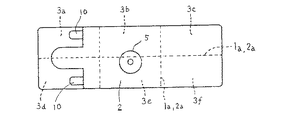
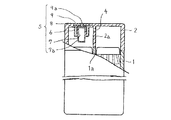
図1は、本発明の一実施形態を示す上面図、図2は図1の要部断面図、図3は図1の一部を切り欠いた正面図であり、図5、図6と同一符号は、同一名称を示す。
【0015】
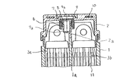
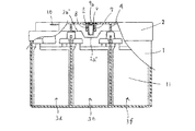
本実施形態に係る電槽1は、上面が開口した箱体からなり、内部が長手方向に延びる一列の隔壁1aと、該隔壁に直交する二列の隔壁1aにより6個の部屋に区画されている。蓋2は、下面が開口した箱体からなり、前記電槽1と同様に隔壁2aにより6個の部屋に区画されている。これら電槽1と蓋2とは、互いの周縁同士と隔壁の縁同士が溶着され、開口面が塞がれて6個のセル室3a〜3fが形成されている。該セル室には正極と負極をセパレータを介して積層された極群11が収納されている。セル室3bと3eとを仕切る蓋2の隔壁2aに排気部5が形成され、この部分の隔壁2aの下端2a’が図3のように排気部5の形成されていない隔壁2aの下端2a’’より下に突出している。このようにすることにより下端2a’と2a’’が同一高さの場合に比べ蓋2を低い位置に取り付けることができるので、極群11と蓋2の間のデッドスペースを減少できる。
【0016】
前記排気部5は、蓋2の上面から下方に凹んだ凹部6と、該凹部6の底壁を貫通し、下部に排気ガス通過口7aを有する筒7と、該筒7の上端に外接嵌合した排気弁8と、該排気弁8を押さえ、凹部6の開口上面を塞ぐ上蓋9とからなり、上蓋9の中心にガスを外部に排出するための排気孔9aを有する。また、該排気部5は中心線がセル室3e側に偏るように形成され、前記通過口7aが隔壁2aから最も離れるように筒7の側面に設けられている。こうすることにより電池が横置された場合、セル室3e内に残存する電解液が通過口7aから排気部5に浸入しにくくしている。
【0017】
各セル室3a〜3fを仕切る蓋の隔壁2aには、セル室3bと3eを仕切る隔壁2aを除いて連通口4が形成され、各セル室3a〜3d,3fで発生した排気ガスを連通口4を通じてセル室3eに集められるようになっている。セル室3eの排気ガスは、通過口7aから排気部5内に充満し、該排気ガスの圧力が所定の値になれば、排気弁8が持ち上げられて排気弁8と筒7との間を通って、排気孔9aから外部に排出される。
【0018】
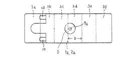
(実施形態2)
図4は、本発明の他の実施形態を示す上面図であり、セル室3a〜3fが長手方向に6個形成されたものであり、排気部5がセル室3cと3dを仕切る蓋2の隔壁2aに一体に形成され、セル室3d側に偏っている。そして、セル室3a〜3c,3e,3fで発生した排気ガスをセル室3dに集中するために、隣接する各セル室を仕切る蓋2の隔壁2aの全てに連通口4を形成している。その他の構成は実施形態1と同様である。
【0019】
【発明の効果】
以上の様に、請求項1によると、隣接するセル室に跨がって排気部を設けているので、セル室の幅を狭くでき、コンパクトな密閉形鉛蓄電池を提供できる。
【0020】
また、請求項2によると、請求項1の効果に加え、電池が横置されても残存する電解液が排気部から漏れにくい密閉形鉛蓄電池を提供できる。
【0021】
さらに、請求項3によると、請求項1の効果に加え、極群と蓋の間のデッドスペースが少なくなり高さの低い密閉形鉛蓄電池を提供できる。
【図面の簡単な説明】
【図1】本発明の一実施形態を示す上面図である。
【図2】図1の要部側断面図である。
【図3】図1の一部切欠き正面図である。
【図4】本発明の他の実施形態を示す上面図である。
【図5】従来の密閉形鉛蓄電池の一例を示す上面図である。
【図6】図5の一部切欠き側面図である。
【符号の説明】
1 電槽
1a 電槽の隔壁
2 蓋
2a 蓋の隔壁
2a’ 排気部下方の蓋の隔壁下縁
2a’’ 排気部側方の蓋の隔壁下縁
3a〜3f セル室
4 連通口
5 排気部
7a 通過口[0001]
BACKGROUND OF THE INVENTION
The present invention relates to a small sealed lead-acid battery, and particularly to an exhaust structure thereof.
[0002]
[Prior art]
Small sealed lead-acid batteries used in motorcycles, etc., are divided into six cell chambers by battery compartment partitions, collecting exhaust gas generated in each cell chamber into one cell chamber, and a lid on the top of the cell chamber A concentrated exhaust structure is often employed in which the exhaust gas is exhausted to the outside from an exhaust section provided in the interior. For example, as shown in FIGS. 5 and 6, the inside of the battery is divided into three in the longitudinal direction by the partition wall 1a of the
[0003]
In addition, in order to prevent the
[0004]
[Problems to be solved by the invention]
In such batteries, downsizing of the outer dimensions has become the most important requirement item. In this case, it is required to reduce the respective dimensions in the height, length, and width directions, and some measures can be taken for the height, but the structure of the exhaust part is made small for the length or width. Because it was not possible, it was an obstacle to miniaturization. That is, in the battery having the structure shown in FIGS. 5 and 6, when the width dimension of the battery (the vertical dimension in FIG. 5) is reduced, the width dimension (a dimension in FIG. 5) of the cell chamber 3e is also reduced. Unless the value is reduced, the
[0005]
Further, in a battery having a structure in which the
[0006]
If the cell chambers are arranged in a row as shown in FIG. 4, the width of the lid on which the
[0007]
In order to solve such a problem, when an exhaust part is formed across adjacent cell chambers and the respective cell chambers and the exhaust part are communicated with each other, when the battery is used horizontally, There is a problem that the flowing electrolytic solution remaining in the gas enters the exhaust port and escapes to the outside.
[0008]
The present invention was made in view of the above problems, and an object, it is possible to attach the vent to be less that the width of the battery having a predetermined size to the lid, the electrolyte An object of the present invention is to provide a sealed lead-acid battery in which liquid does not leak from the exhaust part.
[0009]
[Means for Solving the Problems]
In order to solve the above-mentioned problems, the sealed lead-acid battery of the present invention divides the interior into a plurality of cell chambers by the partition walls of the battery case and the partition walls of the lid, and one of the cell chambers has a lid constituting the lid. Forming an exhaust part in the partition wall, forming a communication port for communicating adjacent cell chambers in the partition wall between the cell chambers, concentrating gas from each cell chamber through the communication port to the exhaust part, The gas is discharged to the outside through a passage port that communicates with the inside of the exhaust portion, and the passage port is formed at a position separated from the partition wall on which the exhaust portion is formed.
[0012]
The communication port is not limited to the partition wall, but may be formed on the back surface of the lid on the top of the partition wall, and the present invention includes these.
[0013]
DETAILED DESCRIPTION OF THE INVENTION
Hereinafter, embodiments of the present invention will be described in detail with reference to the drawings.
[0014]
(Embodiment 1)
FIG. 1 is a top view showing an embodiment of the present invention, FIG. 2 is a cross-sectional view of the main part of FIG. 1, and FIG. 3 is a front view with a part cut away of FIG. A code | symbol shows the same name.
[0015]
The
[0016]
The
[0017]
A
[0018]
(Embodiment 2)
FIG. 4 is a top view showing another embodiment of the present invention, in which six cell chambers 3a to 3f are formed in the longitudinal direction, and the
[0019]
【The invention's effect】
As described above, according to the first aspect, since the exhaust portion is provided across the adjacent cell chambers, the width of the cell chamber can be reduced, and a compact sealed lead-acid battery can be provided.
[0020]
Further, according to
[0021]
Further, according to the third aspect, in addition to the effect of the first aspect, a dead space between the pole group and the lid is reduced, and a sealed lead-acid battery having a low height can be provided.
[Brief description of the drawings]
FIG. 1 is a top view showing an embodiment of the present invention.
2 is a cross-sectional side view of a main part of FIG. 1;
3 is a partially cutaway front view of FIG. 1. FIG.
FIG. 4 is a top view showing another embodiment of the present invention.
FIG. 5 is a top view showing an example of a conventional sealed lead-acid battery.
6 is a partially cutaway side view of FIG. 5. FIG.
[Explanation of symbols]
DESCRIPTION OF
Claims (1)
Priority Applications (1)
| Application Number | Priority Date | Filing Date | Title |
|---|---|---|---|
| JP13250697A JP4088723B2 (en) | 1997-05-22 | 1997-05-22 | Sealed lead acid battery |
Applications Claiming Priority (1)
| Application Number | Priority Date | Filing Date | Title |
|---|---|---|---|
| JP13250697A JP4088723B2 (en) | 1997-05-22 | 1997-05-22 | Sealed lead acid battery |
Publications (3)
| Publication Number | Publication Date |
|---|---|
| JPH10321209A JPH10321209A (en) | 1998-12-04 |
| JPH10321209A5 JPH10321209A5 (en) | 2005-02-10 |
| JP4088723B2 true JP4088723B2 (en) | 2008-05-21 |
Family
ID=15082957
Family Applications (1)
| Application Number | Title | Priority Date | Filing Date |
|---|---|---|---|
| JP13250697A Expired - Lifetime JP4088723B2 (en) | 1997-05-22 | 1997-05-22 | Sealed lead acid battery |
Country Status (1)
| Country | Link |
|---|---|
| JP (1) | JP4088723B2 (en) |
-
1997
- 1997-05-22 JP JP13250697A patent/JP4088723B2/en not_active Expired - Lifetime
Also Published As
| Publication number | Publication date |
|---|---|
| JPH10321209A (en) | 1998-12-04 |
Similar Documents
| Publication | Publication Date | Title |
|---|---|---|
| JP4715089B2 (en) | Lead acid battery | |
| JP5245335B2 (en) | Lead acid battery | |
| JP2010272264A (en) | Lead acid battery | |
| JP2005166318A5 (en) | ||
| JP5446326B2 (en) | Lead acid battery | |
| JP5365046B2 (en) | Lead acid battery | |
| JP5365080B2 (en) | Lead acid battery | |
| JP4088723B2 (en) | Sealed lead acid battery | |
| JP4246600B2 (en) | Battery exhaust structure | |
| JP2009016063A (en) | Storage battery | |
| JP4715091B2 (en) | Lead acid battery | |
| JP2008117583A (en) | Exhaust structure of storage battery | |
| JP2008186690A (en) | Lead acid storage battery | |
| JP5184000B2 (en) | Storage battery exhaust structure | |
| JP4698153B2 (en) | Battery exhaust structure | |
| CN217405482U (en) | Separation device and fuel cell system having the same | |
| JPH09134710A (en) | Storage battery | |
| JP2008177042A (en) | Double-lid exhaust structure for storage battery | |
| JP4715090B2 (en) | Lead acid battery | |
| US20250149728A1 (en) | Power storage device | |
| JP5084396B2 (en) | Storage battery exhaust structure | |
| JPH11312506A (en) | Sealed lead-acid battery | |
| JPH1140124A (en) | Sealed lead-acid battery | |
| CN2342470Y (en) | storage battery | |
| JPH0514456Y2 (en) |
Legal Events
| Date | Code | Title | Description |
|---|---|---|---|
| A521 | Request for written amendment filed |
Free format text: JAPANESE INTERMEDIATE CODE: A523 Effective date: 20040304 |
|
| A621 | Written request for application examination |
Free format text: JAPANESE INTERMEDIATE CODE: A621 Effective date: 20040412 |
|
| A977 | Report on retrieval |
Free format text: JAPANESE INTERMEDIATE CODE: A971007 Effective date: 20050428 |
|
| A711 | Notification of change in applicant |
Free format text: JAPANESE INTERMEDIATE CODE: A712 Effective date: 20051219 |
|
| A131 | Notification of reasons for refusal |
Free format text: JAPANESE INTERMEDIATE CODE: A131 Effective date: 20070905 |
|
| A521 | Request for written amendment filed |
Free format text: JAPANESE INTERMEDIATE CODE: A523 Effective date: 20071017 |
|
| A131 | Notification of reasons for refusal |
Free format text: JAPANESE INTERMEDIATE CODE: A131 Effective date: 20071108 |
|
| A521 | Request for written amendment filed |
Free format text: JAPANESE INTERMEDIATE CODE: A523 Effective date: 20071226 |
|
| TRDD | Decision of grant or rejection written | ||
| A01 | Written decision to grant a patent or to grant a registration (utility model) |
Free format text: JAPANESE INTERMEDIATE CODE: A01 Effective date: 20080130 |
|
| A61 | First payment of annual fees (during grant procedure) |
Free format text: JAPANESE INTERMEDIATE CODE: A61 Effective date: 20080212 |
|
| R150 | Certificate of patent or registration of utility model |
Free format text: JAPANESE INTERMEDIATE CODE: R150 |
|
| FPAY | Renewal fee payment (event date is renewal date of database) |
Free format text: PAYMENT UNTIL: 20110307 Year of fee payment: 3 |
|
| FPAY | Renewal fee payment (event date is renewal date of database) |
Free format text: PAYMENT UNTIL: 20110307 Year of fee payment: 3 |
|
| S111 | Request for change of ownership or part of ownership |
Free format text: JAPANESE INTERMEDIATE CODE: R313111 |
|
| FPAY | Renewal fee payment (event date is renewal date of database) |
Free format text: PAYMENT UNTIL: 20110307 Year of fee payment: 3 |
|
| R360 | Written notification for declining of transfer of rights |
Free format text: JAPANESE INTERMEDIATE CODE: R360 |
|
| FPAY | Renewal fee payment (event date is renewal date of database) |
Free format text: PAYMENT UNTIL: 20110307 Year of fee payment: 3 |
|
| R360 | Written notification for declining of transfer of rights |
Free format text: JAPANESE INTERMEDIATE CODE: R360 |
|
| R371 | Transfer withdrawn |
Free format text: JAPANESE INTERMEDIATE CODE: R371 |
|
| S111 | Request for change of ownership or part of ownership |
Free format text: JAPANESE INTERMEDIATE CODE: R313111 |
|
| FPAY | Renewal fee payment (event date is renewal date of database) |
Free format text: PAYMENT UNTIL: 20110307 Year of fee payment: 3 |
|
| R350 | Written notification of registration of transfer |
Free format text: JAPANESE INTERMEDIATE CODE: R350 |
|
| FPAY | Renewal fee payment (event date is renewal date of database) |
Free format text: PAYMENT UNTIL: 20120307 Year of fee payment: 4 |
|
| FPAY | Renewal fee payment (event date is renewal date of database) |
Free format text: PAYMENT UNTIL: 20120307 Year of fee payment: 4 |
|
| FPAY | Renewal fee payment (event date is renewal date of database) |
Free format text: PAYMENT UNTIL: 20130307 Year of fee payment: 5 |
|
| FPAY | Renewal fee payment (event date is renewal date of database) |
Free format text: PAYMENT UNTIL: 20130307 Year of fee payment: 5 |
|
| FPAY | Renewal fee payment (event date is renewal date of database) |
Free format text: PAYMENT UNTIL: 20140307 Year of fee payment: 6 |
|
| EXPY | Cancellation because of completion of term |