JP4088198B2 - Hydrogen storage tank container and heating device thereof - Google Patents
Hydrogen storage tank container and heating device thereof Download PDFInfo
- Publication number
- JP4088198B2 JP4088198B2 JP2003133514A JP2003133514A JP4088198B2 JP 4088198 B2 JP4088198 B2 JP 4088198B2 JP 2003133514 A JP2003133514 A JP 2003133514A JP 2003133514 A JP2003133514 A JP 2003133514A JP 4088198 B2 JP4088198 B2 JP 4088198B2
- Authority
- JP
- Japan
- Prior art keywords
- hydrogen storage
- storage tank
- heating device
- container
- hydrogen
- Prior art date
- Legal status (The legal status is an assumption and is not a legal conclusion. Google has not performed a legal analysis and makes no representation as to the accuracy of the status listed.)
- Expired - Fee Related
Links
- 239000001257 hydrogen Substances 0.000 title claims description 102
- 229910052739 hydrogen Inorganic materials 0.000 title claims description 102
- UFHFLCQGNIYNRP-UHFFFAOYSA-N Hydrogen Chemical compound [H][H] UFHFLCQGNIYNRP-UHFFFAOYSA-N 0.000 title claims description 101
- 238000010438 heat treatment Methods 0.000 title claims description 66
- XLYOFNOQVPJJNP-UHFFFAOYSA-N water Substances O XLYOFNOQVPJJNP-UHFFFAOYSA-N 0.000 claims description 42
- 239000000463 material Substances 0.000 claims description 7
- 238000012546 transfer Methods 0.000 claims description 5
- 239000011230 binding agent Substances 0.000 claims 1
- 239000000446 fuel Substances 0.000 description 24
- 238000007789 sealing Methods 0.000 description 10
- 239000000956 alloy Substances 0.000 description 5
- 229910045601 alloy Inorganic materials 0.000 description 5
- 239000006227 byproduct Substances 0.000 description 3
- XAGFODPZIPBFFR-UHFFFAOYSA-N aluminium Chemical compound [Al] XAGFODPZIPBFFR-UHFFFAOYSA-N 0.000 description 2
- 229910052782 aluminium Inorganic materials 0.000 description 2
- QVGXLLKOCUKJST-UHFFFAOYSA-N atomic oxygen Chemical compound [O] QVGXLLKOCUKJST-UHFFFAOYSA-N 0.000 description 2
- 239000004020 conductor Substances 0.000 description 2
- 230000007613 environmental effect Effects 0.000 description 2
- 239000001301 oxygen Substances 0.000 description 2
- 229910052760 oxygen Inorganic materials 0.000 description 2
- 239000002918 waste heat Substances 0.000 description 2
- 238000003915 air pollution Methods 0.000 description 1
- 239000003086 colorant Substances 0.000 description 1
- 238000004891 communication Methods 0.000 description 1
- 230000007423 decrease Effects 0.000 description 1
- 238000013461 design Methods 0.000 description 1
- 238000005516 engineering process Methods 0.000 description 1
- 239000007789 gas Substances 0.000 description 1
- 125000004435 hydrogen atom Chemical group [H]* 0.000 description 1
- 230000014759 maintenance of location Effects 0.000 description 1
- 238000000034 method Methods 0.000 description 1
- 238000012986 modification Methods 0.000 description 1
- 230000004048 modification Effects 0.000 description 1
- 239000012495 reaction gas Substances 0.000 description 1
Images

Classifications
-
- H—ELECTRICITY
- H01—ELECTRIC ELEMENTS
- H01M—PROCESSES OR MEANS, e.g. BATTERIES, FOR THE DIRECT CONVERSION OF CHEMICAL ENERGY INTO ELECTRICAL ENERGY
- H01M8/00—Fuel cells; Manufacture thereof
- H01M8/04—Auxiliary arrangements, e.g. for control of pressure or for circulation of fluids
- H01M8/04082—Arrangements for control of reactant parameters, e.g. pressure or concentration
- H01M8/04201—Reactant storage and supply, e.g. means for feeding, pipes
- H01M8/04208—Cartridges, cryogenic media or cryogenic reservoirs
-
- F—MECHANICAL ENGINEERING; LIGHTING; HEATING; WEAPONS; BLASTING
- F17—STORING OR DISTRIBUTING GASES OR LIQUIDS
- F17C—VESSELS FOR CONTAINING OR STORING COMPRESSED, LIQUEFIED OR SOLIDIFIED GASES; FIXED-CAPACITY GAS-HOLDERS; FILLING VESSELS WITH, OR DISCHARGING FROM VESSELS, COMPRESSED, LIQUEFIED, OR SOLIDIFIED GASES
- F17C11/00—Use of gas-solvents or gas-sorbents in vessels
- F17C11/005—Use of gas-solvents or gas-sorbents in vessels for hydrogen
-
- H—ELECTRICITY
- H01—ELECTRIC ELEMENTS
- H01M—PROCESSES OR MEANS, e.g. BATTERIES, FOR THE DIRECT CONVERSION OF CHEMICAL ENERGY INTO ELECTRICAL ENERGY
- H01M8/00—Fuel cells; Manufacture thereof
- H01M8/06—Combination of fuel cells with means for production of reactants or for treatment of residues
- H01M8/0606—Combination of fuel cells with means for production of reactants or for treatment of residues with means for production of gaseous reactants
- H01M8/065—Combination of fuel cells with means for production of reactants or for treatment of residues with means for production of gaseous reactants by dissolution of metals or alloys; by dehydriding metallic substances
-
- Y—GENERAL TAGGING OF NEW TECHNOLOGICAL DEVELOPMENTS; GENERAL TAGGING OF CROSS-SECTIONAL TECHNOLOGIES SPANNING OVER SEVERAL SECTIONS OF THE IPC; TECHNICAL SUBJECTS COVERED BY FORMER USPC CROSS-REFERENCE ART COLLECTIONS [XRACs] AND DIGESTS
- Y02—TECHNOLOGIES OR APPLICATIONS FOR MITIGATION OR ADAPTATION AGAINST CLIMATE CHANGE
- Y02E—REDUCTION OF GREENHOUSE GAS [GHG] EMISSIONS, RELATED TO ENERGY GENERATION, TRANSMISSION OR DISTRIBUTION
- Y02E60/00—Enabling technologies; Technologies with a potential or indirect contribution to GHG emissions mitigation
- Y02E60/30—Hydrogen technology
- Y02E60/32—Hydrogen storage
-
- Y—GENERAL TAGGING OF NEW TECHNOLOGICAL DEVELOPMENTS; GENERAL TAGGING OF CROSS-SECTIONAL TECHNOLOGIES SPANNING OVER SEVERAL SECTIONS OF THE IPC; TECHNICAL SUBJECTS COVERED BY FORMER USPC CROSS-REFERENCE ART COLLECTIONS [XRACs] AND DIGESTS
- Y02—TECHNOLOGIES OR APPLICATIONS FOR MITIGATION OR ADAPTATION AGAINST CLIMATE CHANGE
- Y02E—REDUCTION OF GREENHOUSE GAS [GHG] EMISSIONS, RELATED TO ENERGY GENERATION, TRANSMISSION OR DISTRIBUTION
- Y02E60/00—Enabling technologies; Technologies with a potential or indirect contribution to GHG emissions mitigation
- Y02E60/30—Hydrogen technology
- Y02E60/50—Fuel cells
Landscapes
- Engineering & Computer Science (AREA)
- Chemical Kinetics & Catalysis (AREA)
- Manufacturing & Machinery (AREA)
- Sustainable Development (AREA)
- Sustainable Energy (AREA)
- Chemical & Material Sciences (AREA)
- Life Sciences & Earth Sciences (AREA)
- Electrochemistry (AREA)
- General Chemical & Material Sciences (AREA)
- Mechanical Engineering (AREA)
- General Engineering & Computer Science (AREA)
- Filling Or Discharging Of Gas Storage Vessels (AREA)
- Fuel Cell (AREA)
- Hydrogen, Water And Hydrids (AREA)
Description
【0001】
【発明の属する技術分野】
本発明は、水素貯蔵タンク(hydrogen storage tank)のコンテナ(container)に関するもので、特に、加熱装置(heat device)を備えるコンテナに関するものである。
【0002】
【従来の技術】
近来の空気汚染は非常に深刻で、大部分は、ガソリンエンジンからの排ガスによるものである。よって、ガソリンエンジン(gasoline engine)による汚染は軽視してはならぬ問題であり、更によい環境品質を追求するため、汚染を伴わない燃料電池(fuel cell)により、汚染度が高いガソリンエンジンを代替することが重要である。
【0003】
燃料電池の構造とタイプは、本発明と無関係であるから、詳述を省略する。注意すべきことは、燃料電池は水素と酸素の結合により作用し、酸素は周囲から直接提供され、水素は通常、純水素を含む水素貯蔵タンクから供給されることである。
【0004】
水素貯蔵合金は水素を保存する水素貯蔵タンクに設置される。水素貯蔵タンクが燃料電池に連通する時、水素は水素貯蔵アレイから放出されて、水素を燃料電池に放出する。この時、水素は水素貯蔵合金により放出されて、水素貯蔵タンク内の熱は、水素貯蔵合金により吸収される。これにより、水素貯蔵タンク内の温度は下降する。しかし、水素貯蔵タンク内の温度が低い時、水素貯蔵合金から水素を放出する効率も低下する。その結果、燃料電池に供給する水素の量が不足してしまう。
【0005】
更に、燃料電池が反応する時、水や廃熱等の副産物が生成される。これらをどのように応用するかが重要な課題である。
【0006】
更に、水素を、反応ガスとして用いるシステム、例えば、空調や水素エンジンにおいて、どのようにして水素貯蔵タンクに、正常に水素を供給させるかが重要である。
【0007】
【発明が解決しようとする課題】
本発明は、水素貯蔵タンクを所定の温度下で保持することが出来る水素貯蔵タンクの加熱装置を提供することを目的とする。
【0008】
副産物を適切に応用することが出来る水素貯蔵タンクのコンテナを提供することをもう一つの目的とする。
【0009】
【課題を解決するための手段】
上述の目的を達成するため、本発明は、水素貯蔵タンクが収容できるコンテナの加熱装置を提供する。水素貯蔵タンクは、排水口(discharge port)を備える燃料電池に水素を供給し、加熱装置はウォータージャケット(water jacket)と封鎖素子(seal member)とを備える。ウォータージャケットはコンテナに設置され、燃料電池の排水口と連通している。水素貯蔵タンクがコンテナに設置される時、水素貯蔵タンクはウォータージャケットにより囲繞され、排水口からの水により加熱される。封鎖素子はウォータージャケットとコンテナ間に設置されて、水素貯蔵タンクは、ウォータージャケットに抵接する。
【0010】
好ましい具体例において、加熱装置は、更に、複数の本体と複数のハウジングを備える。本体はコンテナに設置される。ハウジングは本体に対応し、対応する本体と結合される。
【0011】
更に、ハウジングは、第一開口と第二開口とをそれぞれ、備える。本体はそれぞれ凹部を形成し、燃料電池からの水は、本体とハウジングが結合される時、ウォ−タージャケットに流れ込む。本体の形状は水素貯蔵タンクに対応し、ハウジングの形状は、本体に対応する。
【0012】
水素貯蔵タンクは円柱形で、本体とハウジングはその断面が半円の弧形である。
もう一つの好ましい具体例において、ウォータージャケットはアルミニウムからなり、封鎖素子はO型リングである。
【0013】
本発明において、水素貯蔵タンクのコンテナが提供される。コンテナは支承、加熱装置、供給装置、を備える。支承は水素貯蔵タンクを支承する。加熱装置は支承上に設置される。水素貯蔵タンクが支承に設置される時、水素貯蔵タンクは加熱装置に囲繞される。供給装置は加熱装置に連通し、熱導電材(thermal−conductive material)を加熱装置に供給するのに用いられ、水素貯蔵タンクは加熱装置により加熱される。
【0014】
加熱装置はウォータージャケットである。
好ましい具体例において、支承は第一プレートと第二プレートとを備え、水素貯蔵タンクを支承し、水素貯蔵タンクを固定するための結合材を備える。
【0015】
本発明において、水素貯蔵タンクを設置するコンテナのもう一つの加熱装置が提供される。加熱装置はウォータージャケット、供給装置、封鎖素子、を備える。ウォータージャケットはコンテナに設置される。水素貯蔵タンクがコンテナ上に設置される時、水素貯蔵タンクはウォータージャケットに囲繞される。供給装置はウォータージャケットに連通し、熱導電材をウォータージャケットに供給するのに用いられて、水素貯蔵タンクはウォータージャケットにより加熱される。封鎖素子はウォータージャケットとコンテナ間に設置されて、水素貯蔵タンクはウォータージャケットにきっちりと抵接する。
【0016】
【発明の実施の形態】
上述した本発明の目的、特徴、及び長所をいっそう明瞭にするため、以下に本発明の好ましい実施の形態を挙げ、図を参照にしながらさらに詳しく説明する。
【0017】
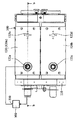
図1〜図3を参照すると、水素貯蔵タンク200のコンテナ100が提供される。水素貯蔵タンク200は燃料電池300に、水素を供給する。燃料電池300は排水口310を形成している。コンテナ100は、支承110、四つの加熱装置120、二つの封鎖素子130、からなる。
【0018】
二つの水素貯蔵タンク200は、本具体例において、支承110により支承されているが、これに限定するものではなく、実際の使用状況に応じて変更することが出来る。
【0019】
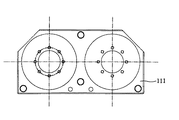
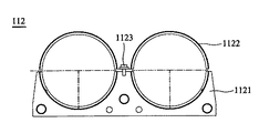
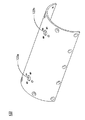
支承110は水素貯蔵タンク200の両端を支承し、第一プレート111と第二プレート112とを備える。第一プレート111は図4で、第二プレート112は図5で示されている。図5を参照すると、第二プレート112はベース1121、トップカバー1122及び固定素子1123、を備える。トップカバー1122は、固定素子1123によりベース1121に結合される。更に、図1〜図3で示されるように、結合材113が第一プレート111に設置されて、水素貯蔵タンク200を、支承110の第一プレート111に固定する。
【0020】
上述のような構成により、支承110内に水素貯蔵タンク200を収納する時、水素貯蔵タンク200は、水素貯蔵タンク200の一端が第一プレート111に抵接し、結合材113に接続されるまで、ベース1121と第二プレート112のトップカバー1122間の円形ホールを突き抜ける。
【0021】
第一プレート111と第二プレート112の形状は、水素貯蔵タンク200と加熱装置120が支承110に設置できれば、図4及び図5で示されるものに限定されない。
【0022】
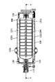
図2で示されるように、加熱装置120は支承110に設置され、二つの本体1211、1212及び二つのハウジング1221、1222、を備える。水素貯蔵タンク200は、二つの本体121と二つのハウジング122に囲繞される。
【0023】
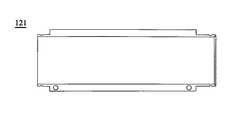
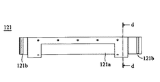
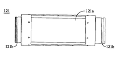
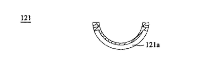
本体121の両端は、支承110の第一プレート111と第二プレート112上に設置される。図6〜図9で示されるように、本体121は凹部121aを形成する。ハウジング122が本体121に結合された後、燃料電池300からの水は、加熱装置120の凹部121aに流れ込む。本体121は両端で溝(groove)121bを形成し、封鎖素子130を設置する。
【0024】
図10を参照すると、ハウジング122は本体121に対応し、本体121に結合されて、加熱装置120の半分を形成する。ハウジング122は、第一開口122aと第二開口122bとを備える。第一開口122aが加熱装置120に流れ込む水の引き込み口として用いられる時、第二開口122bは加熱装置120から流れ出す水の排水口として用いられる。また、第一開口122aが加熱装置120から流れ出す水の排水口として用いられる時、第二開口122bは加熱装置120に流れ込む水の引き込み口として用いられる。図1において、第一開口122aが加熱装置120に流れ込む水の引き込み口として用いられている。特に、第一開口122aは燃料電池300の排水口310と連通する時、燃料電池300により生成される水は、排水口310と第一開口122aとにより、加熱装置120に流れ込む。
【0025】
更に、図1により、燃料電池300からの水がコンテナ100中で循環する過程を説明する。二つの加熱装置120a及び120bは、支承110に設置される。加熱装置120aは第一開口122aと第二開口122bとを備え、加熱装置120bは第一開口122cと第二開口122dとを備える。第一開口122aにより、燃料電池300からの水が加熱装置120aに流れ込んだ後、第二開口122bにより加熱装置120aから流れ出す。その後、パイプ(図示しない)により、加熱装置120aからの水は第二開口122dにより、加熱装置120bに流れ込む。最後に、水は、第一開口122cにより、加熱装置120bから流れ出る。このような配置により、燃料電池300からの水は水素貯蔵タンク200を加熱するのに用いることが出来る。
【0026】
よって、水素貯蔵タンク200は支承110上に設置される時、加熱装置120により囲繞され、燃料電池300の排水口310からの水により加熱される。
【0027】
加熱装置120は、本具体例ではウォータージャケットであるが、これに限定するものではない。
【0028】
更に、本体121の形状は水素貯蔵タンク200に対応し、ハウジング122の形状は本体121に対応する。例えば、水素貯蔵タンク200が円筒形の時、本体121とハウジング122は、断面が半円形である弧形である。
【0029】
本体121とハウジング122は、例えば、アルミニウムなどの熱導電係数が高い材料からなる。よって、加熱装置120と水素貯蔵タンク200間の熱伝達効率は増加する。
【0030】
封鎖素子130は加熱装置120の本体121の溝121b上に設置され、加熱装置120と支承110間に設置される。よって、加熱装置120は水素貯蔵タンク200にきっちりと抵接する。
【0031】
封鎖素子130はO型リングである。
加熱装置120は分離可能であるから、水素貯蔵装置200は封鎖素子130により、加熱装置120に続けて抵接する。その結果、加熱装置120と水素貯蔵装置200間の熱伝達効率は増加する。
【0032】
本発明による水素貯蔵タンクのコンテナの構造は以上のようである。このコンテナは、以下のような長所を有する。加熱装置がコンテナに設置されるため、コンテナ内の水素貯蔵装置は所定温度で維持される。よって、水素貯蔵合金から水素を放出する効率が上昇し、水素は燃料電池に十分に供給される。更に、燃料電池からの水や廃熱等の副産物が加熱装置により応用されて、その他の熱源が不用である。つまり、本発明の設計は、環境保護のコンセプトに基づいている。更に、加熱装置は分離可能で、封鎖素子が支承と加熱装置間に設置されるため、たとえ、温度変化のせいで、水素貯蔵タンクの大きさが変化しても、水素貯蔵タンクは加熱装置にきっちりと抵接する。この結果、加熱装置と水素貯蔵タンク間の熱伝達効率は増加する。
【0033】
本記述では、燃料電池を、水素貯蔵タンクが水素を供給する対象として用いられているが、これに限定するものではなく、本発明の加熱装置は、水素により冷却されるエンジンなど、水素貯蔵タンクに水素を供給することが要求される他の装置に適用することも出来る。
【0034】
更に、本具体例において、加熱装置の熱源は、燃料電池からの水である。しかし、実際はこれに限定するものではなく、例えば、図11で示されるように、加熱装置を設置する十分な空間がある場合は、供給装置400を設置することも出来る。供給装置400は、熱伝達材料を加熱装置120に供給し、水素貯蔵タンクを加熱する。
【0035】
本発明では好ましい実施例を前述の通り開示したが、これらは決して本発明に限定するものではなく、当該技術を熟知する者なら誰でも、本発明の精神と領域を脱しない範囲内で各種の変動や潤色を加えることができ、従って本発明の保護範囲は、特許請求の範囲で指定した内容を基準とする。
【図面の簡単な説明】
【図1】 本発明による水素貯蔵タンクのコンテナを示す図である。
【図2】 図1のb−bに沿った断面図である。
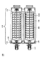
【図3】 図2のc−cに沿った断面図である。
【図4】 図1の第一プレートを示す図である。
【図5】 図1の第二プレートを示す図である。
【図6】 図1のウォータージャケットの本体の底部を示す図である。
【図7】 図1のウォータージャケットの本体の側面図である。
【図8】 図1のウォータージャケットの本体の上視図である。
【図9】 図7のd−dに沿った断面図である。
【図10】 図1のウォータージャケットのハウジングを示す図である。
【図11】 本発明による水素貯蔵タンクのコンテナの具体例の上視図である。
【符号の説明】
100…コンテナ
110…支承
111…第一プレート
112…第二プレート
113…結合材
1121…ベース
1122…トップカバー
1123…固定素子
120、120a、120b…加熱装置
121、1211、1212…本体
121a…凹部
122、1221、1222…ハウジング
122a、122c…第一開口
122b、122d…第二開口
130…封鎖素子
200…水素貯蔵タンク
300…燃料電池
310…排水口
400…供給装置[0001]
BACKGROUND OF THE INVENTION
The present invention relates to a container for a hydrogen storage tank, and more particularly to a container having a heat device.
[0002]
[Prior art]
Modern air pollution is very serious, mostly due to exhaust gas from gasoline engines. Therefore, pollution by gasoline engine is a problem that should not be neglected, and in order to pursue better environmental quality, a fuel cell without pollution is replaced by a highly polluted gasoline engine. It is important to.
[0003]
Since the structure and type of the fuel cell are irrelevant to the present invention, detailed description is omitted. It should be noted that fuel cells operate by a combination of hydrogen and oxygen, oxygen is provided directly from the surroundings, and hydrogen is usually supplied from a hydrogen storage tank containing pure hydrogen.
[0004]
The hydrogen storage alloy is installed in a hydrogen storage tank that stores hydrogen. When the hydrogen storage tank is in communication with the fuel cell, hydrogen is released from the hydrogen storage array, releasing hydrogen to the fuel cell. At this time, hydrogen is released by the hydrogen storage alloy, and heat in the hydrogen storage tank is absorbed by the hydrogen storage alloy. Thereby, the temperature in a hydrogen storage tank falls. However, when the temperature in the hydrogen storage tank is low, the efficiency of releasing hydrogen from the hydrogen storage alloy also decreases. As a result, the amount of hydrogen supplied to the fuel cell is insufficient.
[0005]
Further, when the fuel cell reacts, byproducts such as water and waste heat are generated. How to apply these is an important issue.
[0006]
Furthermore, in a system using hydrogen as a reaction gas, for example, an air conditioner or a hydrogen engine, it is important how hydrogen is normally supplied to a hydrogen storage tank.
[0007]
[Problems to be solved by the invention]
An object of this invention is to provide the heating apparatus of the hydrogen storage tank which can hold | maintain a hydrogen storage tank under predetermined temperature.
[0008]
Another object is to provide a container for a hydrogen storage tank to which the by-products can be appropriately applied.
[0009]
[Means for Solving the Problems]
To achieve the above object, the present invention provides a container heating apparatus that can accommodate a hydrogen storage tank. The hydrogen storage tank supplies hydrogen to a fuel cell having a discharge port, and the heating device includes a water jacket and a seal member. The water jacket is installed in the container and communicates with the drain of the fuel cell. When the hydrogen storage tank is installed in the container, the hydrogen storage tank is surrounded by a water jacket and heated by water from the drain. The sealing element is installed between the water jacket and the container, and the hydrogen storage tank is in contact with the water jacket.
[0010]
In a preferred embodiment, the heating device further comprises a plurality of main bodies and a plurality of housings. The main body is installed in a container. The housing corresponds to the main body and is coupled to the corresponding main body.
[0011]
Further, the housing includes a first opening and a second opening, respectively. Each body forms a recess, and water from the fuel cell flows into the water jacket when the body and housing are joined. The shape of the main body corresponds to the hydrogen storage tank, and the shape of the housing corresponds to the main body.
[0012]
The hydrogen storage tank has a cylindrical shape, and the main body and the housing have an arc shape with a semicircular cross section .
In another preferred embodiment, the water jacket is made of aluminum and the sealing element is an O-ring.
[0013]
In the present invention, a container for a hydrogen storage tank is provided. The container includes a support, a heating device, and a supply device. The support is a hydrogen storage tank. The heating device is installed on the bearing. When the hydrogen storage tank is installed on the bearing, the hydrogen storage tank is surrounded by a heating device. The supply device communicates with the heating device and is used to supply a thermal-conductive material to the heating device, and the hydrogen storage tank is heated by the heating device.
[0014]
The heating device is a water jacket.
In a preferred embodiment, the bearing includes a first plate and a second plate, and supports the hydrogen storage tank and includes a binding material for fixing the hydrogen storage tank.
[0015]
In the present invention, another heating device for a container in which a hydrogen storage tank is installed is provided. The heating device includes a water jacket, a supply device, and a sealing element. The water jacket is installed in the container. When the hydrogen storage tank is installed on the container, the hydrogen storage tank is surrounded by a water jacket. The supply device communicates with the water jacket and is used to supply the thermal conductive material to the water jacket, and the hydrogen storage tank is heated by the water jacket. The sealing element is installed between the water jacket and the container, and the hydrogen storage tank is in full contact with the water jacket.
[0016]
DETAILED DESCRIPTION OF THE INVENTION
In order to further clarify the above-described objects, features, and advantages of the present invention, preferred embodiments of the present invention will be described below and described in more detail with reference to the drawings.
[0017]
1 to 3, a
[0018]
In the present specific example, the two
[0019]
The
[0020]
With the above-described configuration, when the
[0021]
The shapes of the
[0022]
As shown in FIG. 2, the
[0023]
Both ends of the
[0024]
Referring to FIG. 10, the
[0025]
Further, the process of circulating water from the
[0026]
Therefore, when the
[0027]
The
[0028]
Further, the shape of the
[0029]
The
[0030]
The sealing
[0031]
The sealing
Since the
[0032]
The structure of the container of the hydrogen storage tank according to the present invention is as described above. This container has the following advantages. Since the heating device is installed in the container, the hydrogen storage device in the container is maintained at a predetermined temperature. Therefore, the efficiency of releasing hydrogen from the hydrogen storage alloy is increased, and hydrogen is sufficiently supplied to the fuel cell. Furthermore, by-products such as water and waste heat from the fuel cell are applied by the heating device, and other heat sources are unnecessary. That is, the design of the present invention is based on the concept of environmental protection. Furthermore, since the heating device is separable and the sealing element is installed between the support and the heating device, even if the size of the hydrogen storage tank changes due to a temperature change, the hydrogen storage tank is attached to the heating device. I will be in close contact. As a result, the heat transfer efficiency between the heating device and the hydrogen storage tank increases.
[0033]
In this description, the fuel cell is used as an object to which the hydrogen storage tank supplies hydrogen. However, the present invention is not limited to this, and the heating device of the present invention is a hydrogen storage tank such as an engine cooled by hydrogen. The present invention can also be applied to other apparatuses that are required to supply hydrogen.
[0034]
Furthermore, in this specific example, the heat source of the heating device is water from the fuel cell. However, the present invention is not limited to this. For example, as shown in FIG. 11, when there is a sufficient space for installing the heating device, the
[0035]
In the present invention, preferred embodiments have been disclosed as described above. However, the present invention is not limited to the present invention, and any person who is familiar with the technology can make various modifications within the spirit and scope of the present invention. Variations and moist colors can be added, so the protection scope of the present invention is based on what is specified in the claims.
[Brief description of the drawings]
FIG. 1 shows a container of a hydrogen storage tank according to the present invention.
FIG. 2 is a cross-sectional view taken along line bb of FIG.
3 is a cross-sectional view taken along the line cc of FIG.
4 is a view showing a first plate of FIG. 1. FIG.
FIG. 5 is a view showing a second plate of FIG. 1;
6 is a view showing a bottom portion of the main body of the water jacket of FIG. 1. FIG.
7 is a side view of the main body of the water jacket of FIG. 1. FIG.
8 is a top view of the main body of the water jacket of FIG. 1. FIG.
9 is a cross-sectional view taken along the line dd in FIG.
10 is a view showing a housing of the water jacket of FIG. 1. FIG.
FIG. 11 is a top view of a specific example of a container of a hydrogen storage tank according to the present invention.
[Explanation of symbols]
DESCRIPTION OF
Claims (8)
それぞれ前記水素貯蔵タンク(200)の形状に対応する形状を有し、それぞれの外表面に凹部(121a)が形成されるとともに、前記水素貯蔵タンク(200)を間に挟んで、前記水素貯蔵タンク(200)の外壁表面を被うような位置にあるように互いに結合される二つの本体(121)と
それぞれ前記本体の形状に対応する形状を有し、前記二つの凹部(121a)をそれぞれ被う二つのハウジング(122)と
前記水素貯蔵タンク(200)を支持する支承(110)と、
前記二つの本体(121)と前記支承(110)との間に装着されて二つの本体(121)を互いに結合させるとともに、前記二つの本体(121)の内壁と前記水素貯蔵タンク(200)の外壁とを接触させるためのO型リング(130)と
前記凹部(121a)とハウジング(122)とによって形成されるウォータージャケットヘ水を供給するための開口(122a、122b、122c、122d)と、
を備えることを特徴とする加熱装置。A heating device for a hydrogen storage tank (200), comprising:
Each of the hydrogen storage tanks has a shape corresponding to the shape of the hydrogen storage tank (200) , a recess (121a) is formed on each outer surface, and the hydrogen storage tank (200) is interposed between the hydrogen storage tanks. Two main bodies (121) coupled to each other so as to cover the outer wall surface of (200) and a shape corresponding to the shape of each of the main bodies, and each of the two concave portions (121a) being covered. Two housings (122)
A bearing (110) supporting the hydrogen storage tank (200);
Together they are attached to bond the two main body (121) with each other between the two bodies and (121) and said bearing (110), the two inner walls and the hydrogen storage tank of the main body (121) of (200) An opening (122a, 122b, 122c, 122d) for supplying water to the water jacket formed by the O-ring (130) for contacting the outer wall, the recess (121a) and the housing (122) ;
A heating apparatus comprising:
前記水素貯蔵タンク(200)を支持する支承(110)と、
前記支承(110)に支持される前記水素貯蔵タンク(200)を囲繞する加熱装置と、
前記加熱装置に連通し、熱伝達材を前記加熱装置に供給して、前記加熱装置に前記水素貯蔵タンク(200)を加熱させる供給装置と、
前記水素貯蔵タンク(200)からみて前記支承(110)が前記加熱装置の外側となる位置で、前記加熱装置と前記支承(110)間に設置され、前記水素貯蔵タンク(200)を加熱装置に接するようにされるO型リング(130)とを備えることを特徴とするコンテナ。A container for a hydrogen storage tank (200) ,
A bearing (110) supporting the hydrogen storage tank (200) ;
A heating device surrounding the hydrogen storage tank (200) supported by the support (110) ;
A supply device that communicates with the heating device, supplies a heat transfer material to the heating device, and causes the heating device to heat the hydrogen storage tank (200) ;
The support (110) is located outside the heating device when viewed from the hydrogen storage tank (200), and is installed between the heating device and the support (110). The hydrogen storage tank (200) is used as a heating device. A container comprising an O-shaped ring (130) adapted to contact.
前記コンテナに設置された複数の本体(121)と、
前記本体に対応し、前記本体と結合される複数のハウジング(122)と、を備えることを特徴とする請求項4に記載のコンテナ。The heating device is
A plurality of main bodies (121) installed in the container;
5. A container according to claim 4, comprising a plurality of housings (122) corresponding to the body and coupled to the body.
Applications Claiming Priority (1)
| Application Number | Priority Date | Filing Date | Title |
|---|---|---|---|
| TW091110425A TW544971B (en) | 2002-05-17 | 2002-05-17 | Heating device for hydrogen fuel can and hydrogen fuel can container having the heating device |
Publications (2)
| Publication Number | Publication Date |
|---|---|
| JP2004053009A JP2004053009A (en) | 2004-02-19 |
| JP4088198B2 true JP4088198B2 (en) | 2008-05-21 |
Family
ID=29417971
Family Applications (1)
| Application Number | Title | Priority Date | Filing Date |
|---|---|---|---|
| JP2003133514A Expired - Fee Related JP4088198B2 (en) | 2002-05-17 | 2003-05-12 | Hydrogen storage tank container and heating device thereof |
Country Status (3)
| Country | Link |
|---|---|
| US (1) | US6857396B2 (en) |
| JP (1) | JP4088198B2 (en) |
| TW (1) | TW544971B (en) |
Cited By (1)
| Publication number | Priority date | Publication date | Assignee | Title |
|---|---|---|---|---|
| EP3922940A1 (en) | 2020-06-12 | 2021-12-15 | Asia Pacific Fuel Cell Technologies, Ltd. | Heat transferring device and heat transferring component thereof |
Families Citing this family (15)
| Publication number | Priority date | Publication date | Assignee | Title |
|---|---|---|---|---|
| TW577186B (en) * | 2003-01-21 | 2004-02-21 | Asia Pacific Fuel Cell Tech | Device and method for heating hydrogen storage container |
| CN100414166C (en) * | 2003-03-31 | 2008-08-27 | 亚太燃料电池科技股份有限公司 | Hydrogen fuel tank container and heating device thereof |
| KR101126207B1 (en) | 2005-02-28 | 2012-03-26 | 삼성에스디아이 주식회사 | Fuel supply apparatus for reformer and fuel cell system |
| JP4803573B2 (en) * | 2005-03-16 | 2011-10-26 | 株式会社日本製鋼所 | Heat transfer device |
| JP5056181B2 (en) * | 2007-06-06 | 2012-10-24 | トヨタ自動車株式会社 | Hydrogen gas storage device |
| US20090159258A1 (en) * | 2007-12-19 | 2009-06-25 | Kiyoshi Handa | Internal Gas Warming For High Pressure Gas Storage Cylinders With Metal Liners |
| KR101012404B1 (en) * | 2008-09-09 | 2011-02-09 | 삼성전기주식회사 | Fuel Cell Power Generation System |
| FR2952695B1 (en) * | 2009-11-13 | 2012-03-30 | Commissariat Energie Atomique | METAL HYDRIDE HYDROGEN STORAGE TANK |
| TWM395138U (en) * | 2010-01-25 | 2010-12-21 | Rui-Fang Xu | Structure of water-storage and rapid-heating type water heater |
| TWI437756B (en) * | 2010-12-23 | 2014-05-11 | Asia Pacific Fuel Cell Tech | The structure of the bearing module |
| TWI429569B (en) * | 2010-12-23 | 2014-03-11 | Asia Pacific Fuel Cell Tech | Storage tank with compartment structure |
| GB201806840D0 (en) | 2018-04-26 | 2018-06-13 | Univ Of The Western Cape | Metal hydride hydrogen storage arrangement for use in a fuel cell utility vehicle and method of manufacturing the same |
| CN113809357A (en) * | 2020-06-12 | 2021-12-17 | 亚太燃料电池科技股份有限公司 | Heat energy conveying device and heat transfer element thereof |
| US20240159476A1 (en) * | 2020-06-12 | 2024-05-16 | Asia Pacific Fuel Cell Technologies, Ltd. | Heat transferring device and heat transferring component thereof |
| KR20230128775A (en) * | 2022-02-28 | 2023-09-05 | 현대자동차주식회사 | Hydrogen storage system |
Family Cites Families (5)
| Publication number | Priority date | Publication date | Assignee | Title |
|---|---|---|---|---|
| US4566281A (en) * | 1979-02-12 | 1986-01-28 | Ergenics, Inc. | Reaction heat storage method for hydride tanks |
| US5301423A (en) * | 1993-03-11 | 1994-04-12 | Clark Industries, Inc. | One piece cylinder head and liner including a draftless water jacket and method for making same |
| US5544701A (en) * | 1994-07-19 | 1996-08-13 | Elder; Roy W. | Canister warming apparatus |
| JP2001065797A (en) * | 1999-09-01 | 2001-03-16 | Toyota Motor Corp | Hydrogen storage device and hydrogen storage system |
| US6748748B2 (en) * | 2002-06-10 | 2004-06-15 | Nanomix, Inc. | Hydrogen storage and supply system |
-
2002
- 2002-05-17 TW TW091110425A patent/TW544971B/en not_active IP Right Cessation
-
2003
- 2003-05-02 US US10/428,469 patent/US6857396B2/en not_active Expired - Lifetime
- 2003-05-12 JP JP2003133514A patent/JP4088198B2/en not_active Expired - Fee Related
Cited By (1)
| Publication number | Priority date | Publication date | Assignee | Title |
|---|---|---|---|---|
| EP3922940A1 (en) | 2020-06-12 | 2021-12-15 | Asia Pacific Fuel Cell Technologies, Ltd. | Heat transferring device and heat transferring component thereof |
Also Published As
| Publication number | Publication date |
|---|---|
| US6857396B2 (en) | 2005-02-22 |
| JP2004053009A (en) | 2004-02-19 |
| TW544971B (en) | 2003-08-01 |
| US20030215684A1 (en) | 2003-11-20 |
Similar Documents
| Publication | Publication Date | Title |
|---|---|---|
| JP4088198B2 (en) | Hydrogen storage tank container and heating device thereof | |
| CN102132451B (en) | Improved Fuel Cell Stack Flow Hood Airflow Using Air Distribution Devices | |
| CA2274904A1 (en) | Steam reformer with internal hydrogen purification | |
| EA015917B1 (en) | Fuel cell stack flow hood | |
| CN100414166C (en) | Hydrogen fuel tank container and heating device thereof | |
| WO2015005441A1 (en) | Fuel cell device | |
| JP2010238416A (en) | Fuel cell system | |
| JP4863194B2 (en) | Fuel reformer for fuel cell | |
| CN114730894B (en) | Fuel cell module | |
| CN100581990C (en) | Reactor, fuel cell system and electronic equipment | |
| JP7090042B2 (en) | Fuel cell system and fuel cell vehicle | |
| JP5082535B2 (en) | Reactor | |
| JP4316975B2 (en) | Reformer | |
| JP7113374B2 (en) | fuel cell system | |
| JP2020098750A (en) | Fuel battery module | |
| US20240128486A1 (en) | Fuel cell module and fuel cell device | |
| JP5041666B2 (en) | Fuel cell power generation system | |
| US20240145753A1 (en) | Fuel cell module and fuel cell device | |
| JP4254769B2 (en) | Reactor | |
| JP2020004656A (en) | Fuel cell device | |
| JP2008041388A (en) | Fuel cell system | |
| JP3738464B2 (en) | Hydrogen generator | |
| JPWO2019004032A1 (en) | Fuel cell device | |
| JP3389286B2 (en) | Reformer for fuel cell | |
| JP4878466B2 (en) | Fuel reformer for fuel cell |
Legal Events
| Date | Code | Title | Description |
|---|---|---|---|
| A977 | Report on retrieval |
Free format text: JAPANESE INTERMEDIATE CODE: A971007 Effective date: 20050412 |
|
| A131 | Notification of reasons for refusal |
Free format text: JAPANESE INTERMEDIATE CODE: A131 Effective date: 20050510 |
|
| A601 | Written request for extension of time |
Free format text: JAPANESE INTERMEDIATE CODE: A601 Effective date: 20050809 |
|
| A602 | Written permission of extension of time |
Free format text: JAPANESE INTERMEDIATE CODE: A602 Effective date: 20050812 |
|
| A521 | Request for written amendment filed |
Free format text: JAPANESE INTERMEDIATE CODE: A523 Effective date: 20050905 |
|
| A131 | Notification of reasons for refusal |
Free format text: JAPANESE INTERMEDIATE CODE: A131 Effective date: 20060606 |
|
| A601 | Written request for extension of time |
Free format text: JAPANESE INTERMEDIATE CODE: A601 Effective date: 20060904 |
|
| A602 | Written permission of extension of time |
Free format text: JAPANESE INTERMEDIATE CODE: A602 Effective date: 20060907 |
|
| A521 | Request for written amendment filed |
Free format text: JAPANESE INTERMEDIATE CODE: A523 Effective date: 20061204 |
|
| A521 | Request for written amendment filed |
Free format text: JAPANESE INTERMEDIATE CODE: A523 Effective date: 20070110 |
|
| A521 | Request for written amendment filed |
Free format text: JAPANESE INTERMEDIATE CODE: A523 Effective date: 20070115 |
|
| A521 | Request for written amendment filed |
Free format text: JAPANESE INTERMEDIATE CODE: A523 Effective date: 20070118 |
|
| A131 | Notification of reasons for refusal |
Free format text: JAPANESE INTERMEDIATE CODE: A131 Effective date: 20071002 |
|
| RD02 | Notification of acceptance of power of attorney |
Free format text: JAPANESE INTERMEDIATE CODE: A7422 Effective date: 20071025 |
|
| A521 | Request for written amendment filed |
Free format text: JAPANESE INTERMEDIATE CODE: A821 Effective date: 20071116 |
|
| RD04 | Notification of resignation of power of attorney |
Free format text: JAPANESE INTERMEDIATE CODE: A7424 Effective date: 20071116 |
|
| A521 | Request for written amendment filed |
Free format text: JAPANESE INTERMEDIATE CODE: A523 Effective date: 20071219 |
|
| TRDD | Decision of grant or rejection written | ||
| A01 | Written decision to grant a patent or to grant a registration (utility model) |
Free format text: JAPANESE INTERMEDIATE CODE: A01 Effective date: 20080131 |
|
| A61 | First payment of annual fees (during grant procedure) |
Free format text: JAPANESE INTERMEDIATE CODE: A61 Effective date: 20080222 |
|
| FPAY | Renewal fee payment (event date is renewal date of database) |
Free format text: PAYMENT UNTIL: 20110228 Year of fee payment: 3 |
|
| R150 | Certificate of patent or registration of utility model |
Ref document number: 4088198 Country of ref document: JP Free format text: JAPANESE INTERMEDIATE CODE: R150 Free format text: JAPANESE INTERMEDIATE CODE: R150 |
|
| FPAY | Renewal fee payment (event date is renewal date of database) |
Free format text: PAYMENT UNTIL: 20120229 Year of fee payment: 4 |
|
| R250 | Receipt of annual fees |
Free format text: JAPANESE INTERMEDIATE CODE: R250 |
|
| FPAY | Renewal fee payment (event date is renewal date of database) |
Free format text: PAYMENT UNTIL: 20130228 Year of fee payment: 5 |
|
| R250 | Receipt of annual fees |
Free format text: JAPANESE INTERMEDIATE CODE: R250 |
|
| FPAY | Renewal fee payment (event date is renewal date of database) |
Free format text: PAYMENT UNTIL: 20130228 Year of fee payment: 5 |
|
| FPAY | Renewal fee payment (event date is renewal date of database) |
Free format text: PAYMENT UNTIL: 20140228 Year of fee payment: 6 |
|
| R250 | Receipt of annual fees |
Free format text: JAPANESE INTERMEDIATE CODE: R250 |
|
| R250 | Receipt of annual fees |
Free format text: JAPANESE INTERMEDIATE CODE: R250 |
|
| R250 | Receipt of annual fees |
Free format text: JAPANESE INTERMEDIATE CODE: R250 |
|
| R250 | Receipt of annual fees |
Free format text: JAPANESE INTERMEDIATE CODE: R250 |
|
| R250 | Receipt of annual fees |
Free format text: JAPANESE INTERMEDIATE CODE: R250 |
|
| R250 | Receipt of annual fees |
Free format text: JAPANESE INTERMEDIATE CODE: R250 |
|
| R250 | Receipt of annual fees |
Free format text: JAPANESE INTERMEDIATE CODE: R250 |
|
| R250 | Receipt of annual fees |
Free format text: JAPANESE INTERMEDIATE CODE: R250 |
|
| R250 | Receipt of annual fees |
Free format text: JAPANESE INTERMEDIATE CODE: R250 |
|
| LAPS | Cancellation because of no payment of annual fees |