JP4087841B2 - Robot controller - Google Patents
Robot controller Download PDFInfo
- Publication number
- JP4087841B2 JP4087841B2 JP2004368977A JP2004368977A JP4087841B2 JP 4087841 B2 JP4087841 B2 JP 4087841B2 JP 2004368977 A JP2004368977 A JP 2004368977A JP 2004368977 A JP2004368977 A JP 2004368977A JP 4087841 B2 JP4087841 B2 JP 4087841B2
- Authority
- JP
- Japan
- Prior art keywords
- workpiece
- path
- robot
- route
- robot hand
- Prior art date
- Legal status (The legal status is an assumption and is not a legal conclusion. Google has not performed a legal analysis and makes no representation as to the accuracy of the status listed.)
- Active
Links
- 238000013459 approach Methods 0.000 claims description 40
- 238000000926 separation method Methods 0.000 claims description 34
- 230000000007 visual effect Effects 0.000 claims description 22
- 101100522111 Oryza sativa subsp. japonica PHT1-11 gene Proteins 0.000 claims description 14
- 101100522114 Oryza sativa subsp. japonica PHT1-12 gene Proteins 0.000 claims description 13
- 230000033001 locomotion Effects 0.000 claims description 6
- 238000012986 modification Methods 0.000 claims 1
- 230000004048 modification Effects 0.000 claims 1
- 238000000034 method Methods 0.000 description 7
- 238000012937 correction Methods 0.000 description 6
- 238000003384 imaging method Methods 0.000 description 6
- 238000012545 processing Methods 0.000 description 6
- 239000002699 waste material Substances 0.000 description 5
- 238000010586 diagram Methods 0.000 description 2
- 238000005259 measurement Methods 0.000 description 2
- 230000008054 signal transmission Effects 0.000 description 2
- 230000005856 abnormality Effects 0.000 description 1
- 238000007689 inspection Methods 0.000 description 1
- 238000011144 upstream manufacturing Methods 0.000 description 1
Images


Classifications
-
- B—PERFORMING OPERATIONS; TRANSPORTING
- B25—HAND TOOLS; PORTABLE POWER-DRIVEN TOOLS; MANIPULATORS
- B25J—MANIPULATORS; CHAMBERS PROVIDED WITH MANIPULATION DEVICES
- B25J9/00—Programme-controlled manipulators
- B25J9/16—Programme controls
- B25J9/1656—Programme controls characterised by programming, planning systems for manipulators
- B25J9/1664—Programme controls characterised by programming, planning systems for manipulators characterised by motion, path, trajectory planning
-
- G—PHYSICS
- G05—CONTROLLING; REGULATING
- G05B—CONTROL OR REGULATING SYSTEMS IN GENERAL; FUNCTIONAL ELEMENTS OF SUCH SYSTEMS; MONITORING OR TESTING ARRANGEMENTS FOR SUCH SYSTEMS OR ELEMENTS
- G05B2219/00—Program-control systems
- G05B2219/30—Nc systems
- G05B2219/40—Robotics, robotics mapping to robotics vision
- G05B2219/40431—Grid of preoptimised paths as function of target position, choose closest, fine adapt
-
- G—PHYSICS
- G05—CONTROLLING; REGULATING
- G05B—CONTROL OR REGULATING SYSTEMS IN GENERAL; FUNCTIONAL ELEMENTS OF SUCH SYSTEMS; MONITORING OR TESTING ARRANGEMENTS FOR SUCH SYSTEMS OR ELEMENTS
- G05B2219/00—Program-control systems
- G05B2219/30—Nc systems
- G05B2219/40—Robotics, robotics mapping to robotics vision
- G05B2219/40564—Recognize shape, contour of object, extract position and orientation
-
- G—PHYSICS
- G05—CONTROLLING; REGULATING
- G05B—CONTROL OR REGULATING SYSTEMS IN GENERAL; FUNCTIONAL ELEMENTS OF SUCH SYSTEMS; MONITORING OR TESTING ARRANGEMENTS FOR SUCH SYSTEMS OR ELEMENTS
- G05B2219/00—Program-control systems
- G05B2219/30—Nc systems
- G05B2219/45—Nc applications
- G05B2219/45063—Pick and place manipulator
Landscapes
- Engineering & Computer Science (AREA)
- Robotics (AREA)
- Mechanical Engineering (AREA)
- Numerical Control (AREA)
- Manipulator (AREA)
Description
本発明は、ワークの位置を視覚センサによって検出し、検出されたワークの位置に基づいてロボットハンドが向かうべき目標位置を補正してワークに対してロボットハンドを接近及び離隔させるロボット制御装置に関する。 The present invention relates to a robot control apparatus that detects a position of a workpiece by a visual sensor, corrects a target position to which the robot hand should go based on the detected position of the workpiece, and moves the robot hand toward and away from the workpiece.
ロボットシステムでは、基準位置を予め定めておき、ワークが基準位置に配置されていることを前提として、ワークに対するロボットハンドの接近経路又は離隔経路を教示し、ロボットハンドの動作を規定する必要がある。このような経路の教示は、ロボットハンドを経路に沿って直接動かす直接的教示や経路上の始点、経由点及び終点などを指定しその間の軌道を補間により求めさせる間接的教示などにより行われる。 In a robot system, it is necessary to prescribe a reference position and specify an approach path or a separation path of the robot hand with respect to the work and prescribe the operation of the robot hand on the assumption that the work is arranged at the reference position. . Such route teaching is performed by direct teaching in which the robot hand is moved directly along the route or indirect teaching in which a start point, a via point, an end point, and the like on the route are designated and a trajectory between them is obtained by interpolation.
ところが、実際には、ワークを正確に基準位置に配置することは困難であり、ワークは基準位置からずれて載置されることが多い。そこで、実際にワークが載置されている位置にロボットハンドを移動させるために、ロボットシステムに視覚センサ等を設けて、実際のワークの位置と基準位置との位置ズレを検出し、予め教示されているロボットハンドの移動経路の教示点のうち目標位置(接近経路の終点又は離隔経路の始点)を補正する必要がある。一方で、ロボットハンドの移動経路は、ロボットハンド自体やロボットハンドに把持されたワークが他の物体に干渉しないように規定される必要がある。そこで、実際のワークの位置がいかなる位置であっても、他の物体と干渉の恐れがないように規定された共通の経路に沿って特定点まで移動させ、その特定点でその特定経路から外れて補正された目標位置にロボットハンドを移動させるようにしていた。 However, in practice, it is difficult to accurately place the workpiece at the reference position, and the workpiece is often placed out of the reference position. Therefore, in order to move the robot hand to the position where the workpiece is actually placed, a visual sensor or the like is provided in the robot system to detect the positional deviation between the actual workpiece position and the reference position, and is taught in advance. It is necessary to correct the target position (the end point of the approach path or the start point of the separation path) among the teaching points of the movement path of the robot hand. On the other hand, the movement path of the robot hand needs to be defined so that the robot hand itself and the workpiece gripped by the robot hand do not interfere with other objects. Therefore, no matter what the actual workpiece position is, it moves to a specific point along a specified common path so that there is no risk of interference with other objects, and deviates from the specific path at that specific point. The robot hand is moved to the corrected target position.
従来技術では、ロボットハンドは、ワークの位置(すなわち、補正後の目標位置)にかかわらず、共通の経路に沿って特定点まで移動した後に、特定点からワークまで移動していたので、ワークがある範囲の位置に配置されている場合には、遠回りの移動経路に沿ってロボットハンドを移動させることになる。このため、ロボットハンドの動作に無駄が生じ、サイクルタイムを長くする原因となっていた。 In the prior art, the robot hand moves from the specific point to the workpiece after moving to the specific point along the common path regardless of the position of the workpiece (that is, the corrected target position). When the robot hand is arranged in a certain range of positions, the robot hand is moved along a detour movement path. For this reason, the operation of the robot hand is wasted and the cycle time is lengthened.
よって、本発明の目的は、上記従来技術に存する問題を解決して、実際にワークが配置されている位置に応じた経路に沿ってロボットハンドを移動させ、ロボットハンドの動作のサイクルタイムを低減させることにある。 Therefore, the object of the present invention is to solve the above-mentioned problems in the prior art and move the robot hand along the path according to the position where the workpiece is actually arranged, thereby reducing the cycle time of the operation of the robot hand. There is to make it.
本発明は、上記目的に鑑み、ワークの位置を視覚センサによって検出し、検出されたワークの位置に基づいてロボットハンドが向かうべき目標位置を補正して前記ワークに対してロボットハンドを接近及び離隔させるロボット制御装置において、ワークの戴置が許容される範囲を複数の領域に分割し、分割した各領域においてロボットハンドの接近経路及び離隔経路を設定するために特定の代表位置を選定し、前記選定された特定の代表位置に前記ロボットハンドを接近させるための接近経路と前記選定された特定の代表位置から前記ロボットハンドを離隔させるための離隔経路を各領域に対応付けた経路パターンとして経路パターン記憶手段に記憶しておき、前記視覚センサによって検出されたワークの位置が前記複数の領域のうちの何れの領域に属するかに基づいて、前記経路パターン記憶手段に記憶された複数の経路パターンから、前記視覚センサによって検出されたワークの位置が属する領域に対応付けられた経路パターンを選択して、選択された経路パターンについての前記代表位置を前記ロボットハンドが向かうべき目標位置として設定した後、前記ロボットハンドが向かうべき目標位置と前記視覚センサによって検出されたワークの位置とが一致するように前記選択された経路パターンを修正したものを接近経路及び離隔経路として規定し、規定された前記接近経路及び前記離隔経路に沿って前記ワークに向かって前記ロボットハンドを移動させ、前記ワークを把持、搬送するようにしたロボット制御装置を提供する。 In view of the above-described object, the present invention detects the position of a workpiece by a visual sensor, corrects the target position to which the robot hand should go based on the detected position of the workpiece, and moves the robot hand toward and away from the workpiece. In the robot control device, the range in which the placement of the workpiece is allowed is divided into a plurality of regions, and a specific representative position is selected in order to set the approach route and the separation route of the robot hand in each divided region, after the separation path in order to separate the said robot hand from the selected the particular representative position an approaching route to the route pattern associated with each region for the to approach the robot hand to selected the particular representative position is stored in the road-pattern storage means, any position of the workpiece detected by the visual sensor of the plurality of regions Based on belongs to the region, the path from the path pattern of multiple stored in the pattern storing means, and selects a route pattern associated with the region in which the position of the workpiece detected by the visual sensor belongs, selects After the representative position of the route pattern is set as a target position to which the robot hand should go, the selection is made so that the target position to which the robot hand should go and the position of the workpiece detected by the visual sensor match. The corrected route pattern is defined as an approach route and a separation route, the robot hand is moved toward the workpiece along the defined approach route and the separation route, and the workpiece is gripped and conveyed. Provided is a robot control apparatus.
本発明のロボット制御装置では、実際にワークが配置された位置に応じて、経路パターン記憶手段に予め記憶された複数の経路パターンの中から接近経路及び離隔経路が選択され、ロボットハンドが向かうべき目標位置と実際のワークの位置とが一致するように、選択された経路パターンにおいて経路パターンを特定するために選定された特定の目標位置を補正することによって、接近経路及び離隔経路を修正する。したがって、経路パターン記憶手段にワークの位置に適した経路パターンを記憶させることができ、実際のワークの位置に応じて、ロボットハンドと他の物体との干渉を避けながらロボットハンドの動作の無駄を低減させるような経路パターンを容易に規定することが可能となる。また、ワークの載置が許容される範囲を複数の領域に分割することで、各領域の検討範囲が狭くなるので、干渉を避けることができる経路の検討が容易になると共に、実際のワークの位置と選択される経路パターンとの対応付けも容易になる。 In the robot control apparatus according to the present invention, the approach route and the separation route are selected from a plurality of route patterns stored in advance in the route pattern storage unit according to the position where the workpiece is actually arranged, and the robot hand should head. The approach path and the separation path are corrected by correcting the specific target position selected for specifying the path pattern in the selected path pattern so that the target position matches the actual workpiece position. Therefore, it is possible to store a route pattern suitable for the position of the workpiece in the route pattern storage means, and waste of the operation of the robot hand while avoiding interference between the robot hand and other objects according to the actual workpiece position. It is possible to easily define a route pattern to be reduced. In addition, by dividing the range in which workpiece placement is allowed into multiple areas, the examination range for each area is narrowed, making it easier to study routes that can avoid interference and It is also easy to associate the position with the selected route pattern.
一つの実施形態として、前記制御装置は、前記ロボットハンドが向かうべき目標位置と前記視覚センサによって検出されたワークの位置とが一致するように前記選択された経路パターンを平行移動させたものを接近経路及び離隔経路として規定することができる。このように接近経路及び離隔経路を規定する場合、実際のワークの位置に応じてワークへの接近方向及びワークからの離隔方向を設定することができ、他の物体との衝突を回避させるように経路を設定することが容易となる。 In one embodiment, the control device approaches a target obtained by translating the selected path pattern so that a target position to which the robot hand should go and a work position detected by the visual sensor coincide with each other. It can be defined as a route and a remote route. When the approach path and the separation path are defined in this way, the approach direction to the workpiece and the separation direction from the workpiece can be set according to the actual position of the workpiece, so that the collision with other objects can be avoided. It becomes easy to set a route.
接近経路と離隔経路とを異なった経路にする必要性がないときには、一つのワークに対する前記接近経路と前記離隔経路とは同じ経路としてもよい。 When there is no need to make the approach route and the separation route different from each other, the approach route and the separation route for one workpiece may be the same route.
前記視覚センサによって検出されたワークの位置の各座標値の少なくとも一つが予め定められた閾値を越えているとき、前記ロボット制御装置は警報を発し、前記ロボットハンドの動作を停止させることが好ましい。この場合、干渉の可能性を検討されていない領域内をロボットハンドが移動することを回避させ、実際に干渉が発生することを防止することができる。 Preferably, when at least one of the coordinate values of the workpiece position detected by the visual sensor exceeds a predetermined threshold, the robot controller issues an alarm and stops the operation of the robot hand. In this case, it is possible to prevent the robot hand from moving in an area where the possibility of interference is not considered, and to prevent actual interference from occurring.
前記接近経路及び前記離隔経路は、始点と終点とを指定し、指定された始点と終点との間を補間により結ぶことによって規定されてもよく、始点と終点と該始点と該終点との間の少なくとも一つの経由点とを指定し、指定された各点の間を補間により結ぶことによって規定されてもよい。
また、前記視覚センサによって検出されるワークの位置は、予め定められた基準位置に対するワークの相対位置としてもよく、絶対座標系における位置であってもよい。
The approach path and the separation path may be defined by specifying a start point and an end point and connecting the specified start point and end point by interpolation, and between the start point, the end point, the start point, and the end point. May be defined by specifying at least one via point and connecting the specified points by interpolation.
Further, the position of the workpiece detected by the visual sensor may be a relative position of the workpiece with respect to a predetermined reference position, or may be a position in an absolute coordinate system.
本発明のロボット制御装置によれば、実際のワークの位置に応じて、他の物体との干渉を避けながらロボットハンドの動作の無駄を低減させるような経路パターンを経路パターン記憶手段に記憶された複数の経路パターンの中から選択することができる。したがって、他の物体との干渉を回避しながらロボットハンドの動作のサイクルタイムを短縮することが可能となる。 According to the robot control apparatus of the present invention, a route pattern that reduces waste of the operation of the robot hand while avoiding interference with other objects is stored in the route pattern storage unit according to the actual position of the workpiece. A plurality of route patterns can be selected. Therefore, it is possible to shorten the cycle time of the operation of the robot hand while avoiding interference with other objects.
以下、添付図面を参照して、本発明の実施形態を詳細に説明する。
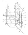
図1は本発明のロボット制御装置を備えるロボットシステムの全体構成図、図2は本発明のロボット制御装置における処理のフローチャート、図3は本発明のロボット制御装置の経路パターン記憶手段内においてワーク載置範囲の各分割領域と対応付けられた経路パターンを説明するための説明図を示している。
Hereinafter, embodiments of the present invention will be described in detail with reference to the accompanying drawings.
FIG. 1 is an overall configuration diagram of a robot system provided with a robot control apparatus of the present invention, FIG. 2 is a flowchart of processing in the robot control apparatus of the present invention, and FIG. 3 is a work placement in a path pattern storage means of the robot control apparatus of the present invention. An explanatory view for explaining a route pattern associated with each divided region of the placement range is shown.
最初に、図1を参照して、本発明のロボット制御装置16を使用するロボットシステム10の全体構成について説明する。ロボットシステム10は、ロボットアーム12と、ロボットアーム12の先端に取り付けられたロボットハンド14と、ロボットアーム12及びロボットハンド14の動作を制御するロボット制御装置16と、ワークWの位置を検出するための視覚センサ18と、経路パターンを記憶するための経路パターン記憶手段20とを備えており、コンベアや作業台のようなワーク載置面22上に載置されたワークWにロボットハンド14を接近させ、ロボットハンド14でワークWを保持した後、別の場所にワークWを搬送する。
First, the overall configuration of the robot system 10 using the
ロボットアーム12は、公知のタイプのものであり、ロボット制御装置16からの動作指令に基づいてロボットハンド14を所定の位置に移動させることができるように構成されている。ロボットハンド14は、把持又は吸着などによりワークWを保持できる公知のタイプのものであり、ロボット制御装置16からの動作指令に基づいてロボットアーム12に対して任意の向きに旋回できるようになっている。
The
視覚センサ18は、三次元計測を行えるタイプのものであり、ロボットハンド14と並んで設けられた撮像装置18aと、撮像装置18aから得た画像情報を処理するための画像処理装置18bとから構成されている。撮像装置18aとしては、例えば、2台のCCDカメラを用いたステレオ方式のものが使用される。撮像装置18aは、信号ケーブルなどの信号伝達手段18cによって画像処理装置18bに接続されており、画像処理装置18bは、ビデオ信号のような撮像装置18aから得られた信号を処理して3次元計測を行い、ワーク載置面22上に載置されたワークWの位置を検出する。ワークWの位置情報として、絶対座標系における座標を測定してもよく、予め定められた基準点に対する相対座標を測定してもよい。後者の場合、例えば、ワーク載置面22上に予め定められた基準位置Oに配置されたと仮定されたワークW0に対する実際のワークWの相対位置を測定する。
The
ロボット制御装置16は、一般的に使用されている周知のタイプのもので、メインボードには、CPU、ROM、RAM、不揮発性RAMなどが装備されている。ROMには、ロボットアーム12及びロボットハンド14を制御するシステムソフトウェアが格納される。このシステムソフトウェアは、通常、RAM上にコピーされた上でCPUにより実行される。また、ユーザが作成する動作指令を含むロボットプログラム(動作プログラム)は、不揮発性RAMに格納される。このロボットプログラムも、通常、RAM上にコピーされた上でCPUにより実行される。ロボット制御装置16のメインボードは、サーボアンプを介してロボットアームを駆動するサーボモータ24と接続され、またサーボモータ24のエンコーダやその他のI/O信号(外部入出力信号)の信号線と接続される。また、ロボット制御装置16には、教示操作盤用の入出力インターフェイスを介して、ディスプレイ付の教示操作盤(図示せず)が接続されてもよい。
The
経路パターン記憶手段20は、メモリ、RAMなどの記憶装置によって構成されており、通常、ロボット制御装置16の一部として形成される。
The path pattern storage unit 20 is configured by a storage device such as a memory or a RAM, and is usually formed as a part of the
次に、図2を参照して、上記ロボット制御装置16におけるロボット制御処理について説明する。まず、ワークWの載置が許容される範囲であるワーク載置範囲RAが指定され、ワーク載置範囲RAが複数の領域R1〜R4に分割される(ステップS100)。例えば、図3に示されているようにワーク載置範囲RAが平面であり、ワークWが載置されるべき基準位置Oを中心とした直交相対座標系が規定されている場合、ワーク載置範囲RAは、X軸及びY軸について相対座標系の原点(すなわち、基準位置O)から各座標が最も遠い点P1〜P4を指定することによって行われる。各点P1〜P4の指定は、座標値を入力することによって行ってもよく、ロボットハンド14を実際に上記の点に移動させることによって行ってもよい。図3では、直交座標系のXY平面がX軸及びY軸によって仕切られた四つの領域に分割されているが、ワーク載置範囲RAの指定及びその分割は他の方法により行うことも可能である。なお、ワーク載置範囲RAが立体的である場合には、X軸、Y軸及びZ軸について原点から最も遠い少なくとも八つの点を指定すればよい。
Next, a robot control process in the
次に、分割された各領域R1〜R4ごとに適した経路パターンPT1〜PT4が指定され、これら経路パターンPT1〜PT4が各分割領域R1〜R4に対応付けて経路パターン記憶手段20に記憶される(ステップS102)。例えば、図3に示されているように、四つに分割された領域R1〜R4のそれぞれにおいて、経路パターンを規定するために任意の点を代表位置として選定し、選定された代表位置を目標位置として目標位置にロボットハンド14を接近させるための接近経路と目標位置からロボットハンド14を離隔させるための離隔経路として経路パターンPT1〜PT4を規定し、各分割領域R1〜R4に経路パターンPT1〜PT4を対応付ける。図3には、各分割領域R1〜R4における代表位置に配置されたワークW1〜W4と、各分割領域R1〜R4の代表位置への接近経路として規定された経路パターンPT11、PT2〜PT4及び各分割領域R1〜R4の代表位置からの離隔経路として規定された経路パターンPT12、PT2〜PT4とが示されている。通常、経路パターンPT2〜PT4のように、接近経路と離隔経路とに対して、共通の経路パターンが対応付けられるが、ワークWの形状などから、接近時と離隔時で異なる経路に沿ってロボットハンド14を移動させることが好ましい場合には、図3の経路パターンPT1のように、接近経路と離隔経路とに対して異なる経路パターンPT11、PT12が対応付けられてもよい。 Next, route patterns PT1 to PT4 suitable for each of the divided regions R1 to R4 are designated, and these route patterns PT1 to PT4 are stored in the route pattern storage unit 20 in association with the divided regions R1 to R4. (Step S102). For example, as shown in FIG. 3, in each of the four divided regions R1 to R4, an arbitrary point is selected as a representative position in order to define a route pattern, and the selected representative position is set as a target. Route patterns PT1 to PT4 are defined as an approach route for causing the robot hand 14 to approach the target position as a position and a separation route for separating the robot hand 14 from the target position, and the route patterns PT1 to PT4 are defined in the divided regions R1 to R4. Associate PT4. In FIG. 3, the workpieces W1 to W4 arranged at the representative positions in the divided areas R1 to R4, the path patterns PT11, PT2 to PT4 defined as the approach paths to the representative positions of the divided areas R1 to R4, and the respective Path patterns PT12 and PT2 to PT4 defined as separation paths from the representative positions of the divided areas R1 to R4 are shown. Usually, like the route patterns PT2 to PT4, a common route pattern is associated with the approach route and the separation route. However, due to the shape of the workpiece W, the robot follows different routes at the time of approach and separation. When it is preferable to move the hand 14, different route patterns PT11 and PT12 may be associated with the approach route and the separation route as in the route pattern PT1 of FIG.
本願において使用される用語「目標位置」は、説明の便宜上、ワークWが配置されている又は配置されているはずの位置を意味し、接近経路の場合には終点を、離隔経路の場合には始点を指すものとする。 The term “target position” used in the present application means a position at which the workpiece W is or should be arranged for convenience of explanation. In the case of an approach route, the end point is used. Point to the starting point.
経路パターンPT1〜PT4は、図3に示されているように非直線的経路として規定される場合には、教示点として、始点と、終点と、始点と終点との間の少なくとも一つの経由点の座標をそれぞれ指定し、指定された各点間を各軸補間、直線補間又は円弧補間などにより結ぶことによって規定される。しかしながら、経路パターンが直線的経路として規定される場合などには、教示点として、始点と終点の座標のみを指定することにより経路パターンを規定することも可能である。なお、各点の座標の指定は、動作プログラム中の指令又は操作盤からの入力によって行ってもよく、ロボットアーム12及びロボットハンド14を手動で自由に動かせるようにしてロボットハンド14を所望の位置まで移動させてその位置におけるロボット機構部の各動作軸や視覚センサ18からの情報に基づいて自動的に入力させることによって行ってもよい。
When the path patterns PT1 to PT4 are defined as non-linear paths as shown in FIG. 3, at least one waypoint between a start point, an end point, and a start point and an end point is used as a teaching point. Are specified, and the specified points are connected by axis interpolation, linear interpolation or circular interpolation. However, when the route pattern is defined as a linear route, the route pattern can be defined by designating only the coordinates of the start point and the end point as teaching points. The coordinates of each point may be specified by a command in the operation program or input from the operation panel. The robot arm 14 and the robot hand 14 can be manually moved freely to move the robot hand 14 to a desired position. And may be automatically input based on information from each motion axis of the robot mechanism unit and the
次に、ワーク載置面22にワークWが載置されると、視覚センサ18によってワークWの位置が検出される。詳細には、ロボットハンド14に設けられた撮像装置18aによって実際にワーク載置面22に載置されたワークWの画像情報を取得し、取得した画像情報を信号伝達手段18cを介して画像処理装置18bに送り、画像処理によってワークWの位置を検出する(ステップS104)。このとき、絶対座標系におけるワークWの位置座標を検出してもよく、ワーク載置面22上の基準位置Oに配置されていると仮定されたワークW0に対する相対位置又はワーク載置範囲RAの相対座標系における座標を検出してもよい。ロボット制御装置16は、検出されたワークWの位置情報を受け取ると、ワークWの位置がワーク載置範囲RA内に入っているかを確認する(ステップS106)。具体的には、ワークWの各位置座標がワーク載置範囲RAを指定した際の各座標軸の最大値と最小値の間の値である場合に、ワークWがワーク載置範囲RA内に配置されていると判断する。
Next, when the workpiece W is placed on the
ロボット制御装置16は、ワークWがワーク載置範囲RA内に配置されていると判断すると、経路パターン記憶手段20に記憶された複数の経路パターンPT1〜PT4のうちで、検出されたワークWの位置の属する分割領域R1〜R4に対応付けられた経路パターンPT1〜PT4を選択する(ステップS108)。しかしながら、この経路パターンPT1〜PT4は、ワークWの位置の属する分割領域R1〜R4内の代表位置を目標位置として規定されたものであり、目標位置とワークWの位置とが通常一致しておらず、この経路パターンPT1〜PT4をそのまま接近経路として用いてもロボットハンド14を実際のワークWの位置に正確に移動させることはできない。そこで、検出されたワークWの位置に合わせて、選択された経路パターンPT1〜PT4の修正が行われる(ステップS110)。
When the
経路パターンPT1〜PT4の修正は、例えば、視覚センサによって検出されたワークの位置の座標と既知の代表位置の座標とに基づいてワークWの位置が属する分割領域R1〜R4の代表位置に対する実際のワークWの位置の相対座標を求め、経路パターンPT1〜PT4の目標位置(すなわち、接近経路の終点又は離隔経路の始点)がワークWの位置となるように、経路パターンPT1〜PT4を規定する始点、終点及び経由点のぞれぞれの各座標値に代表位置に対するワークWの相対位置の各相対座標値を加算して経路パターンPT1〜PT4の全ての教示点、すなわち始点、終点及び経由点の座標を補正し、経路パターンPT1〜PT4を平行移動させることによって行われる。これは、接近経路と離隔経路とで同じ経路パターンを使用する場合(PT2〜PT4)も異なる経路パターンを使用する場合(PT1:PT11;PT12)も同じである。このように修正した経路パターンPT1〜PT4を接近経路又は離隔経路として使用することにより、ワークWの位置に応じて適した接近経路又は離隔経路が規定されることになり、ロボットハンド14と他の物体との衝突を回避しつつロボットハンド14の無駄な動作を低減させることが可能になる。 For example, the correction of the path patterns PT1 to PT4 is performed on the representative positions of the divided regions R1 to R4 to which the position of the work W belongs based on the coordinates of the position of the work detected by the visual sensor and the coordinates of the known representative position. The relative coordinates of the position of the workpiece W are obtained, and the starting points for defining the path patterns PT1 to PT4 so that the target positions of the path patterns PT1 to PT4 (that is, the end point of the approach path or the starting point of the separation path) are the positions of the workpiece W In addition, the relative coordinate values of the relative position of the workpiece W with respect to the representative position are added to the respective coordinate values of the end point and the via point, and all the teaching points of the path patterns PT1 to PT4, that is, the start point, the end point, and the via point This is performed by correcting the coordinates of and moving the path patterns PT1 to PT4 in parallel. This is the same when the same route pattern is used for the approach route and the separation route (PT2 to PT4) and when different route patterns are used (PT1: PT11; PT12). By using the route patterns PT1 to PT4 thus corrected as the approach route or the separation route, a suitable approach route or separation route is defined according to the position of the workpiece W. It is possible to reduce useless movement of the robot hand 14 while avoiding collision with an object.
また、経路パターンPT1〜PT4の修正の代替的な方法として、接近経路のための経路パターンPT11、PT2〜PT4の修正が、経路パターンPT11、PT2〜PT4を規定する教示点のうちの終点の座標のみをワークWの位置の座標と一致するように補正することによって行われるようにすることもできる。この場合でも、選択された経路パターンPT11、PT2〜PT4はワークWが属する分割領域R1〜R4に適した接近経路として規定されているので、ロボットハンド14の動作の無駄を低減させることが可能である。離隔経路のための経路パターンPT12、PT2〜PT4の修正は、同様に、経路パターンPT12、PT2〜PT4を規定する教示点のうちの始点の座標のみをワークWの位置座標と一致するように補正することによって行われる。これは、接近経路と離隔経路とで同じ経路パターンを使用する場合(PT2〜PT4)も異なる経路パターンを使用する場合(PT1:PT11;PT12)も同じである。 As an alternative method of correcting the route patterns PT1 to PT4, the correction of the route patterns PT11 and PT2 to PT4 for the approach route is the coordinates of the end points of the teaching points that define the route patterns PT11 and PT2 to PT4. It is also possible to perform the correction by correcting only to match the coordinates of the position of the workpiece W. Even in this case, since the selected route patterns PT11 and PT2 to PT4 are defined as approach routes suitable for the divided regions R1 to R4 to which the workpiece W belongs, it is possible to reduce the waste of the operation of the robot hand 14. is there. Similarly, the correction of the path patterns PT12, PT2 to PT4 for the separation path is corrected so that only the coordinates of the start point of the teaching points defining the path patterns PT12, PT2 to PT4 coincide with the position coordinates of the workpiece W. Is done by doing. This is the same when the same route pattern is used for the approach route and the separation route (PT2 to PT4) and when different route patterns are used (PT1: PT11; PT12).
このようにして経路パターン記憶手段20に記憶された複数の経路パターンPT1〜PT4の中から選択された経路パターンPT1〜PT4を修正した後、ロボット制御装置16は、修正した経路パターンPT1〜PT4を接近経路又は離隔経路として設定し、設定された接近経路及び離隔経路に沿ってロボットハンド14を移動させる(ステップS112)。そして、一つのワークWに対する動作サイクルが終了すると、ステップS104に戻り、次のワークWについて、同様の動作を繰り返す。
After correcting the route patterns PT1 to PT4 selected from the plurality of route patterns PT1 to PT4 stored in the route pattern storage means 20 in this way, the
一方、ステップS106において、ワークWの位置がワーク載置範囲RA内に入っていないと判断されたとき、すなわちワークWの各位置座標のいずれか一つがワーク載置範囲RAを指定した際の各座標軸の最大値と最小値の間に入っていないとき、ロボット制御装置16は、ロボットハンド14又はそれに保持されるワークWが他の物体と干渉する危険性があると判断し、警報を発して動作プログラムの実行を停止させ、ロボットハンド14の動作を停止させる。この場合、ワークWがワーク載置面22上の基準位置Oから許容範囲以上にはずれて配置されたことを意味し、上流側の動作異常が疑われるので、操作者は点検等を行えばよい。
On the other hand, when it is determined in step S106 that the position of the workpiece W is not within the workpiece placement range RA, that is, each of the position coordinates when the workpiece W has designated the workpiece placement range RA. When it is not between the maximum value and the minimum value of the coordinate axes, the
このようにして、ワークWの位置に応じて、適した接近経路及び離隔経路が規定される結果、ロボットハンド14と他の物体との干渉を回避させつつロボットハンド14の無駄のない動作が可能となり、サイクルタイムの短縮を図ることができる。 In this way, as a result of the appropriate approach path and separation path being defined according to the position of the workpiece W, it is possible to operate the robot hand 14 without waste while avoiding interference between the robot hand 14 and other objects. Thus, the cycle time can be shortened.
以上、図示された実施形態に基づいて本発明のロボット制御装置16及びそれを使用したロボットシステム10について説明したが、本発明のロボット制御装置16は、図示される実施形態に限定されるものではない。例えば、上記実施形態では、ワーク載置範囲RAを分割した各領域R1〜R4に経路パターンPT1〜PT4を対応付ける際に、経路パターンPT1〜PT4を規定するために各分割領域R1〜R4において選定された代表位置を目標位置として経路パターンPT1〜PT4が指定されている。しかしながら、経路パターンPT1〜PT4の指定は、必ずしも上記手法に従う必要はなく、例えば、ワーク載置面22上の基準位置Oに配置されているワークWの位置、すなわち相対座標系における原点を目標位置として経路パターンPT1〜PT4を指定することも可能である。ただし、この場合には、ロボットハンド14の動作の無駄を低減させるために、検出されたワークWの位置に応じた経路パターンPT1〜PT4の修正は、経路パターンPT1〜PT4の目標位置がワークWの位置となるように、経路パターンPT1〜PT4を規定する始点、終点及び経由点のそれぞれの各座標値に各領域R1〜R4における代表位置に対するワークWの位置の相対位置の各相対座標値を加算して経路パターンPT1〜PT4の始点、終点及び経由点の座標を補正し、経路パターンPT1〜PT4を平行移動させることによって行われることが好ましい。
The
14 ロボットハンド
16 ロボット制御装置
18 視覚センサ
20 経路パターン記憶手段
PT1 経路パターン
PT2 経路パターン
PT3 経路パターン
PT4 経路パターン
RA ワーク載置範囲
R1 分割領域
R2 分割領域
R3 分割領域
R4 分割領域
W ワーク
14
Claims (7)
ワーク(W)の戴置が許容される範囲を複数の領域(R1,R2,R3,R4)に分割し、分割した各領域(R1,R2,R3,R4)においてロボットハンド(14)の接近経路(PT11,PT2,PT3,PT4)及び離隔経路(PT12、PT2,PT3,PT4)を設定するために特定の代表位置を選定し、前記選定された特定の代表位置に前記ロボットハンド(14)を接近させるための接近経路(PT11,PT2,PT3,PT4)と前記選定された特定の代表位置から前記ロボットハンド(14)を離隔させるための離隔経路(PT12、PT2,PT3,PT4)を各領域(R1,R2,R3,R4)に対応付けた経路パターンとして経路パターン記憶手段(20)に記憶しておき、前記視覚センサ(18)によって検出されたワーク(W)の位置が前記複数の領域(R1,R2,R3,R4)のうちの何れの領域に属するかに基づいて、前記経路パターン記憶手段(20)に記憶された複数の経路パターン(PT1,PT2,PT3,PT4)から、前記視覚センサ(18)によって検出されたワーク(W)の位置が属する領域(R1;R2;R3;R4)に対応付けられた経路パターン(PT1;PT2;PT3;PT4)を選択して、選択された経路パターン(PT1;PT2;PT3;PT4)についての前記代表位置を前記ロボットハンド(14)が向かうべき目標位置として設定した後、前記ロボットハンド(14)が向かうべき目標位置と前記視覚センサ(18)によって検出されたワーク(W)の位置とが一致するように前記選択された経路パターン(PT1;PT2;PT3;PT4)を修正したものを接近経路(PT11;PT2;PT3;PT4)及び離隔経路(PT12;PT2;PT3;PT4)として規定し、規定された前記接近経路(PT11;PT2;PT3;PT4)及び前記離隔経路(PT12;PT2;PT3;PT4)に沿って前記ワークに向かって前記ロボットハンド(14)を移動させ、前記ワーク(W)を把持、搬送するようにしたことを特徴とするロボット制御装置。 The position of the workpiece (W) detected by the visual sensor (18), with respect to the corrected target position to the robot hand (14) is directed on the basis of the detected position of the workpiece (W) the work (W) In the robot control device (16) for approaching and separating the robot hand (14) ,
The range in which the workpiece (W) is allowed to be placed is divided into a plurality of regions (R1, R2, R3, R4), and the robot hand (14) approaches the divided regions (R1, R2, R3, R4). A specific representative position is selected to set the path (PT11, PT2, PT3, PT4) and the separation path (PT12, PT2, PT3, PT4), and the robot hand (14) is set to the selected specific representative position. An approach path (PT11, PT2, PT3, PT4) for approaching and a separation path (PT12, PT2, PT3, PT4) for separating the robot hand (14) from the selected specific representative position. regions (R1, R2, R3, R4) to be the associated path pattern is stored in the route pattern storage means (20), search by the visual sensor (18) Based on whether position of the workpiece (W) belongs to one area of the plurality of regions (R1, R2, R3, R4 ), said path pattern storage means (20) to store the number of double the route pattern from (PT1, PT2, PT3, PT4 ), said visual sensor (18) by belongs area position of the detected workpiece (W) (R1; R2; R3; R4) on the associated path pattern (PT1 PT2; PT3; PT4) and setting the representative position of the selected route pattern (PT1; PT2; PT3; PT4) as a target position to which the robot hand (14) should go , then the robot the selected route as the position of the hand (14) detected by said visual sensor to the target position should be headed (18) work (W) matches Turn (PT1; PT2; PT3; PT4 ) approach route a modification of the (PT11; PT2; PT3; PT4 ) and leaving path (PT12; PT2; PT3; PT4 ) as defined, defined the approaching path (PT11 PT2; PT3; PT4) and the separation path (PT12; PT2; PT3; PT4 ) to move the robot hand (14) toward the workpiece so that the workpiece (W) is gripped and conveyed. A robot control device characterized by that.
Priority Applications (4)
| Application Number | Priority Date | Filing Date | Title |
|---|---|---|---|
| JP2004368977A JP4087841B2 (en) | 2004-12-21 | 2004-12-21 | Robot controller |
| EP05027674A EP1676679A3 (en) | 2004-12-21 | 2005-12-16 | Robot controller for correcting a target position of a robot hand by means of a visual sensor |
| CNB2005101326470A CN100396453C (en) | 2004-12-21 | 2005-12-20 | Robot controller |
| US11/311,351 US20060149421A1 (en) | 2004-12-21 | 2005-12-20 | Robot controller |
Applications Claiming Priority (1)
| Application Number | Priority Date | Filing Date | Title |
|---|---|---|---|
| JP2004368977A JP4087841B2 (en) | 2004-12-21 | 2004-12-21 | Robot controller |
Publications (2)
| Publication Number | Publication Date |
|---|---|
| JP2006175532A JP2006175532A (en) | 2006-07-06 |
| JP4087841B2 true JP4087841B2 (en) | 2008-05-21 |
Family
ID=36097221
Family Applications (1)
| Application Number | Title | Priority Date | Filing Date |
|---|---|---|---|
| JP2004368977A Active JP4087841B2 (en) | 2004-12-21 | 2004-12-21 | Robot controller |
Country Status (4)
| Country | Link |
|---|---|
| US (1) | US20060149421A1 (en) |
| EP (1) | EP1676679A3 (en) |
| JP (1) | JP4087841B2 (en) |
| CN (1) | CN100396453C (en) |
Cited By (1)
| Publication number | Priority date | Publication date | Assignee | Title |
|---|---|---|---|---|
| DE102017008475A1 (en) | 2016-09-16 | 2018-03-22 | Fanuc Corporation | MACHINE LEARNING DEVICE, ROBOT SYSTEM AND MACHINE LEARNING METHOD FOR LEARNING A ROBOT OPERATION PROGRAM |
Families Citing this family (33)
| Publication number | Priority date | Publication date | Assignee | Title |
|---|---|---|---|---|
| WO2008154932A1 (en) * | 2007-06-18 | 2008-12-24 | Syddansk Universitet | Determining a robot path |
| JP4347386B2 (en) * | 2008-01-23 | 2009-10-21 | ファナック株式会社 | Processing robot program creation device |
| US8862269B2 (en) * | 2008-08-29 | 2014-10-14 | Abb Research Ltd. | Robotic picking of parts from a bin |
| EP2331301B1 (en) * | 2008-08-29 | 2018-10-17 | ABB Research Ltd. | Robotic picking of parts from a bin using force feedback |
| WO2011031523A2 (en) | 2009-08-27 | 2011-03-17 | Abb Research Ltd. | Robotic picking of parts from a parts holding bin |
| US20110295408A1 (en) * | 2010-05-27 | 2011-12-01 | Toyota Motor Engineering & Manufacturing North America, Inc. | Process for positioning a workpiece |
| WO2013027251A1 (en) * | 2011-08-19 | 2013-02-28 | 株式会社安川電機 | Robot system, robot control device, robot hand and method for controlling robot |
| US8694160B2 (en) * | 2011-08-24 | 2014-04-08 | Yamazaki Mazak Corporation | NC machine tool system |
| KR102153663B1 (en) * | 2011-09-02 | 2020-09-21 | 브룩스 오토메이션 인코퍼레이티드 | Time-optimal trajectories for robotic transfer devices |
| JP5911299B2 (en) | 2011-12-27 | 2016-04-27 | キヤノン株式会社 | Information processing apparatus, information processing apparatus control method, and program |
| JP2014222393A (en) * | 2013-05-13 | 2014-11-27 | キヤノン株式会社 | Moving body arrangement determination method, measuring apparatus, processing device, and program |
| JP6005299B2 (en) * | 2013-11-28 | 2016-10-12 | 三菱電機株式会社 | Robot system and control method of robot system |
| US9138895B2 (en) * | 2014-01-10 | 2015-09-22 | Recognition Robotics, Inc. | Method for picking up an article using a robot arm and associated system |
| JP5824173B1 (en) * | 2014-02-28 | 2015-11-25 | ファナック株式会社 | Article alignment apparatus and article alignment method for aligning articles using robot, and article transfer system provided with article alignment apparatus |
| WO2017015898A1 (en) * | 2015-07-29 | 2017-02-02 | Abb 瑞士股份有限公司 | Control system for robotic unstacking equipment and method for controlling robotic unstacking |
| JP6517762B2 (en) | 2016-08-23 | 2019-05-22 | ファナック株式会社 | A robot system that learns the motion of a robot that a human and a robot work together |
| US11039893B2 (en) * | 2016-10-21 | 2021-06-22 | Globus Medical, Inc. | Robotic surgical systems |
| JP6450727B2 (en) * | 2016-10-28 | 2019-01-09 | ファナック株式会社 | Apparatus, method, program, and recording medium for simulating article alignment work performed by robot |
| CN106625726A (en) * | 2016-12-29 | 2017-05-10 | 吴中区穹窿山德毅新材料技术研究所 | Arm part of industrial robot |
| WO2018120208A1 (en) * | 2016-12-30 | 2018-07-05 | 深圳配天智能技术研究院有限公司 | Method and device for determining stacking path pattern, and robot |
| WO2019002898A1 (en) * | 2017-06-30 | 2019-01-03 | Siemens Industry Software Ltd. | Method and system for determining joint values of an external axis in robot manufacturing |
| CN110869174B (en) | 2017-07-10 | 2023-12-05 | 海别得公司 | Computer-implemented method and system for generating a material handling robot tool path |
| JP6626065B2 (en) * | 2017-10-31 | 2019-12-25 | ファナック株式会社 | Robot teaching device that warns or corrects the displacement of the teaching point or teaching line |
| JP7233858B2 (en) * | 2018-06-13 | 2023-03-07 | オムロン株式会社 | ROBOT CONTROL DEVICE, ROBOT CONTROL METHOD, AND ROBOT CONTROL PROGRAM |
| US10776949B2 (en) | 2018-10-30 | 2020-09-15 | Liberty Reach Inc. | Machine vision-based method and system for measuring 3D pose of a part or subassembly of parts |
| JP6871220B2 (en) * | 2018-11-08 | 2021-05-12 | ファナック株式会社 | Control system |
| WO2020142498A1 (en) * | 2018-12-31 | 2020-07-09 | Abb Schweiz Ag | Robot having visual memory |
| DE202019101782U1 (en) * | 2019-03-28 | 2019-04-25 | Fft Produktionssysteme Gmbh & Co. Kg | Mounting Arrangement Light |
| CN114025925A (en) * | 2019-06-27 | 2022-02-08 | 川崎重工业株式会社 | Substrate scanning and mapping device, scanning and mapping method thereof and scanning and mapping teaching method |
| CN111230876B (en) * | 2020-02-06 | 2021-11-02 | 腾讯科技(深圳)有限公司 | Method and device for moving article, intelligent equipment and storage medium |
| DE112021001173T5 (en) * | 2020-02-21 | 2023-01-19 | Fanuc Corporation | Deburring device and control system |
| US11707843B2 (en) * | 2020-04-03 | 2023-07-25 | Fanuc Corporation | Initial reference generation for robot optimization motion planning |
| CN114347008B (en) * | 2022-01-18 | 2024-06-25 | 广东原点智能技术有限公司 | Unordered workpiece grabbing method and device based on industrial robot and intelligent terminal |
Family Cites Families (27)
| Publication number | Priority date | Publication date | Assignee | Title |
|---|---|---|---|---|
| US5579444A (en) * | 1987-08-28 | 1996-11-26 | Axiom Bildverarbeitungssysteme Gmbh | Adaptive vision-based controller |
| US4942539A (en) * | 1988-12-21 | 1990-07-17 | Gmf Robotics Corporation | Method and system for automatically determining the position and orientation of an object in 3-D space |
| JP2710850B2 (en) * | 1989-03-27 | 1998-02-10 | キヤノン株式会社 | Work holding device, work and its storage case |
| US5314722A (en) * | 1989-06-29 | 1994-05-24 | Fanuc Ltd | Method of applying a material to a rotating object by using a robot |
| JPH0736989B2 (en) * | 1990-01-19 | 1995-04-26 | トキコ株式会社 | Control method for industrial robot |
| JP2779072B2 (en) * | 1991-01-28 | 1998-07-23 | ファナック株式会社 | Robot teaching method |
| JPH04343178A (en) * | 1991-05-20 | 1992-11-30 | Sony Corp | Image processor |
| US5380978A (en) * | 1991-07-12 | 1995-01-10 | Pryor; Timothy R. | Method and apparatus for assembly of car bodies and other 3-dimensional objects |
| US5577130A (en) * | 1991-08-05 | 1996-11-19 | Philips Electronics North America | Method and apparatus for determining the distance between an image and an object |
| JPH05127718A (en) * | 1991-11-08 | 1993-05-25 | Fujitsu Ltd | Automatic generation device for hand tip track of manipulator |
| JPH07261821A (en) * | 1994-03-16 | 1995-10-13 | Fanuc Ltd | Robot track planning method taking deflection due to load into consideration |
| JP3418456B2 (en) * | 1994-06-23 | 2003-06-23 | ファナック株式会社 | Robot position teaching tool and robot position teaching method |
| US5495410A (en) * | 1994-08-12 | 1996-02-27 | Minnesota Mining And Manufacturing Company | Lead-through robot programming system |
| US5572102A (en) * | 1995-02-28 | 1996-11-05 | Budd Canada Inc. | Method and apparatus for vision control of welding robots |
| JPH0970780A (en) * | 1995-09-06 | 1997-03-18 | Fanuc Ltd | Tool shape correcting method of robot |
| JP3834088B2 (en) * | 1995-11-10 | 2006-10-18 | ファナック株式会社 | A vision sensor robot system for tracking multiple robots |
| WO1997024206A1 (en) * | 1995-12-27 | 1997-07-10 | Fanuc Ltd | Composite sensor robot system |
| US6445964B1 (en) * | 1997-08-04 | 2002-09-03 | Harris Corporation | Virtual reality simulation-based training of telekinegenesis system for training sequential kinematic behavior of automated kinematic machine |
| JPH11300670A (en) * | 1998-04-21 | 1999-11-02 | Fanuc Ltd | Article picking-up device |
| US5959425A (en) * | 1998-10-15 | 1999-09-28 | Fanuc Robotics North America, Inc. | Vision guided automatic robotic path teaching method |
| JP3326472B2 (en) * | 1999-11-10 | 2002-09-24 | 独立行政法人 航空宇宙技術研究所 | Articulated robot |
| JP2002172575A (en) * | 2000-12-07 | 2002-06-18 | Fanuc Ltd | Teaching device |
| JP3715537B2 (en) * | 2001-02-19 | 2005-11-09 | 本田技研工業株式会社 | Interference avoidance method and program for articulated robot |
| JP2003148914A (en) * | 2001-11-08 | 2003-05-21 | Fanuc Ltd | Position detector and taking-out device using position detection |
| JP3702257B2 (en) * | 2002-08-23 | 2005-10-05 | ファナック株式会社 | Robot handling device |
| KR100571834B1 (en) * | 2004-02-27 | 2006-04-17 | 삼성전자주식회사 | Method and apparatus of detecting dust on the floor in a robot for cleaning |
| WO2006019970A2 (en) * | 2004-07-14 | 2006-02-23 | Braintech Canada, Inc. | Method and apparatus for machine-vision |
-
2004
- 2004-12-21 JP JP2004368977A patent/JP4087841B2/en active Active
-
2005
- 2005-12-16 EP EP05027674A patent/EP1676679A3/en not_active Withdrawn
- 2005-12-20 CN CNB2005101326470A patent/CN100396453C/en not_active Expired - Fee Related
- 2005-12-20 US US11/311,351 patent/US20060149421A1/en not_active Abandoned
Cited By (3)
| Publication number | Priority date | Publication date | Assignee | Title |
|---|---|---|---|---|
| DE102017008475A1 (en) | 2016-09-16 | 2018-03-22 | Fanuc Corporation | MACHINE LEARNING DEVICE, ROBOT SYSTEM AND MACHINE LEARNING METHOD FOR LEARNING A ROBOT OPERATION PROGRAM |
| DE102017008475B4 (en) | 2016-09-16 | 2021-08-12 | Fanuc Corporation | MACHINE LEARNING DEVICE, ROBOT SYSTEM AND MACHINE LEARNING METHOD FOR LEARNING A ROBOT OPERATING PROGRAM |
| US11511420B2 (en) | 2016-09-16 | 2022-11-29 | Fanuc Corporation | Machine learning device, robot system, and machine learning method for learning operation program of robot |
Also Published As
| Publication number | Publication date |
|---|---|
| EP1676679A3 (en) | 2008-03-19 |
| US20060149421A1 (en) | 2006-07-06 |
| CN1792573A (en) | 2006-06-28 |
| CN100396453C (en) | 2008-06-25 |
| JP2006175532A (en) | 2006-07-06 |
| EP1676679A2 (en) | 2006-07-05 |
Similar Documents
| Publication | Publication Date | Title |
|---|---|---|
| JP4087841B2 (en) | Robot controller | |
| US8155789B2 (en) | Device, method, program and recording medium for robot offline programming | |
| US9895810B2 (en) | Cooperation system having machine tool and robot | |
| EP3542969B1 (en) | Working-position correcting method and working robot | |
| EP3542973B1 (en) | Work robot and work position correction method | |
| JP2009110190A (en) | Control device of robot for workpiece conveyance | |
| WO2012169374A1 (en) | Workpiece-processing system | |
| US10394216B2 (en) | Method and system for correcting a processing path of a robot-guided tool | |
| JP2021035708A (en) | Production system | |
| JP2016187846A (en) | Robot, robot controller and robot system | |
| CN109465817B (en) | Robot system, robot control device, and method for manufacturing workpiece | |
| US20220388179A1 (en) | Robot system | |
| JP6088190B2 (en) | Processing system and processing method thereof | |
| JP6860735B1 (en) | Transport system, transport system control method, and transport system control program | |
| CN109789555B (en) | Robot system and method for operating the same | |
| US10786901B2 (en) | Method for programming robot in vision base coordinate | |
| JP5446887B2 (en) | Control device, robot, robot system, and robot tracking method | |
| JP5088187B2 (en) | Robot installation method and robot production system | |
| CN110154043B (en) | Robot system for learning control based on machining result and control method thereof | |
| JP6816060B2 (en) | Work robot system and work robot | |
| JP2010149225A (en) | Robot system, device and method for controlling robot system | |
| WO2024062535A1 (en) | Robot control device | |
| WO2023053374A1 (en) | Control device and robot system | |
| JP2023017385A (en) | Robot control method, robot control system, control device and control program | |
| TW202313285A (en) | robot system |
Legal Events
| Date | Code | Title | Description |
|---|---|---|---|
| A977 | Report on retrieval |
Free format text: JAPANESE INTERMEDIATE CODE: A971007 Effective date: 20070808 |
|
| A131 | Notification of reasons for refusal |
Free format text: JAPANESE INTERMEDIATE CODE: A131 Effective date: 20070828 |
|
| A521 | Request for written amendment filed |
Free format text: JAPANESE INTERMEDIATE CODE: A523 Effective date: 20071024 |
|
| TRDD | Decision of grant or rejection written | ||
| A01 | Written decision to grant a patent or to grant a registration (utility model) |
Free format text: JAPANESE INTERMEDIATE CODE: A01 Effective date: 20080205 |
|
| A61 | First payment of annual fees (during grant procedure) |
Free format text: JAPANESE INTERMEDIATE CODE: A61 Effective date: 20080221 |
|
| FPAY | Renewal fee payment (event date is renewal date of database) |
Free format text: PAYMENT UNTIL: 20110228 Year of fee payment: 3 |
|
| R150 | Certificate of patent or registration of utility model |
Ref document number: 4087841 Country of ref document: JP Free format text: JAPANESE INTERMEDIATE CODE: R150 Free format text: JAPANESE INTERMEDIATE CODE: R150 |
|
| FPAY | Renewal fee payment (event date is renewal date of database) |
Free format text: PAYMENT UNTIL: 20110228 Year of fee payment: 3 |
|
| FPAY | Renewal fee payment (event date is renewal date of database) |
Free format text: PAYMENT UNTIL: 20120229 Year of fee payment: 4 |
|
| FPAY | Renewal fee payment (event date is renewal date of database) |
Free format text: PAYMENT UNTIL: 20120229 Year of fee payment: 4 |
|
| FPAY | Renewal fee payment (event date is renewal date of database) |
Free format text: PAYMENT UNTIL: 20130228 Year of fee payment: 5 |
|
| FPAY | Renewal fee payment (event date is renewal date of database) |
Free format text: PAYMENT UNTIL: 20140228 Year of fee payment: 6 |