JP4087547B2 - Computed tomography equipment - Google Patents
Computed tomography equipment Download PDFInfo
- Publication number
- JP4087547B2 JP4087547B2 JP2000148407A JP2000148407A JP4087547B2 JP 4087547 B2 JP4087547 B2 JP 4087547B2 JP 2000148407 A JP2000148407 A JP 2000148407A JP 2000148407 A JP2000148407 A JP 2000148407A JP 4087547 B2 JP4087547 B2 JP 4087547B2
- Authority
- JP
- Japan
- Prior art keywords
- rotation
- transmission data
- subject
- tomography apparatus
- radiation
- Prior art date
- Legal status (The legal status is an assumption and is not a legal conclusion. Google has not performed a legal analysis and makes no representation as to the accuracy of the status listed.)
- Expired - Lifetime
Links
Images


Description
【0001】
【発明の属する技術分野】
本発明は、非破壊検査装置のうちのコンピュータ断層撮影方法および装置に係り、特に撮影の高速化、あるいは画像の高品質化に寄与し得るようにしたコンピュータ断層撮影方法および装置に関するものである。
【0002】
【従来の技術】
近年、小型電子部品等を高分解能で検査することを目的として、高分解能型の産業用のコンピュータ断層撮影装置(以下、CTスキャナ)が製作されるようになってきている。
【0003】
図13は、この種の従来の高分解能型CTスキャナのシステム構成例を示す概要図であり、これは透過像と断面像の両方が得られるものである。
【0004】
図13において、X線管101と、このX線管101から放射されるコーン状のX線ビーム102を2次元の空間分解能をもって検出する検出器103が対向して配置され、このX線ビーム102中の被検体104の透過像を得るようになっている。
【0005】
透過像は、リアルタイムで動画像として表示することもできれば、データ処理部109で加算してノイズを低減させて表示することもできる。
【0006】
回転テーブル105および回転昇降機構106は、シフト機構107によりX線管101に近づけたり遠ざけたりされ、撮影距離が変更され、撮影距離を小さくした場合、撮影倍率を上げることができる。
【0007】
断面像を撮影する場合には、回転テーブル105上の被検体104を回転昇降機構106により回転させながら多数の透過像を得る。
【0008】
この多数の透過像をデータ処理部109で処理して、回転軸112に直交する撮影面111を通る透過像から、この撮影面111上の断面像を得る。
【0009】
その再構成法としては、主に例えば「CTスキャナ」(岩井喜典編:コロナ社)等に示されているフィルタ補正逆投影法(FBP法)が用いられる。
【0010】
被検体104の断面像位置の変更は、被検体104を回転軸112方向に昇降させて行なうが、回転テーブル105を同時に回転および昇降させるヘリカルスキャンを行なって、1回の撮影で撮影面111にほぼ平行な複数の断面像(3次元像)を得る方法もある。
【0011】
さらに、ヘリカルスキャンを行ない、なおかつ撮影面111の外を通る透過像も使って撮影断層面111にほぼ平行な複数の断面像を得る方法もある。
【0012】
この時の再構成法としては、FBP法の応用として、例えば次のような文献に記載されている。
【0013】
(文献1)「CT装置」(株)東芝 荒舘 博、南部 恭二郎、“特開平4-224736号公報”
ここにある第1の再構成法は、撮影面111の外を通る透過像面が撮影面111に対して傾斜するのを平行面と見なして逆投影しているため、若干、回転軸112方向の分解能が低下するのに対して、同文献にある第2の再構成法は、傾斜に従って逆投影しているため、回転軸112方向の分解能を上げることができる。
【0014】
この第2の再構成法は、下記の文献に記載されている方法(フェルドカンプ法)をヘリカルスキャンに対して適用したものと言える。
【0015】
(文献2)“Practica1 cone-beam algorithm”L.A.Fe1dkamp, L.C.Davis, and J.W.Kress J.0pt.Soc.Am./Vol.1,No.6,pp.612-619/June1984
【0016】
【発明が解決しようとする課題】
ところで、最近では、CTスキャナを用いた検査に対する要求が強く、被検体の種類や検査内容も拡大しつつある。このため、画質の高品質化の要求や撮影の高速化の要求が、益々高くなる傾向にある。
【0017】
しかしながら、上述した従来の高分解能型CTスキャナで、コーン状のX線ビーム102を用いて、複数の断面像を一回のスキャンで得る場合、断面像の再構成に要する時間が長く、撮影の高速化のネックになるという問題がある。
【0018】
また、前述した文献1、文献2等には、コーン状のX線ビーム102を用いた(また同時にヘリカルスキャンした)場合の具体的な再構成の高速化の手法については記載されていない。
【0019】
一方、上述した従来の高分解能型CTスキャナでは、被検体104をX線の焦点に近づけることで、高分解能の画像が得られる特徴を有しているが、他方ファン状ではなくコーン状のX線ビーム102が被検体104に照射されることから、被検体104で散乱されて検出器103に入射する散乱X線が増加し、被検体104によっては断面像が不鮮明になり、十分な検査が行なえないという問題がある。
【0020】
また、被検体104により、柔らかく変形し易い場合等があり、撮影中に動きが生じて断面像が不鮮明になるという問題がある。
【0021】
さらに、任意に選択した撮影条件によっては、再構成のフィルタ関数が不適当で、ノイズの大きい画像になってしまうことがある。そして、このような場合には、フィルタ関数を再度選択して再構成し直している。
【0022】
本発明の目的は、撮影の高速化あるいは画像の高品質化に寄与することが可能なコンピュータ断層撮影方法および装置を提供することにある。
【0023】
【課題を解決するための手段】
上記の目的を達成するために、請求項1に対応する発明のコンピュータ断層撮影装置は、 放射線ビームを放射する放射線源と、前記放射線源からの放射線ビームを2次元の空間分解能をもって検出する放射線検出器と、前記放射線ビーム内で被検体を相対回転させる回転手段と、前記放射線ビーム内で被検体を前記回転の軸方向に相対移動させる並進手段を有し、前記回転手段による回転と前記並進手段による相対移動とをほぼ同時に行ないながら透過データを収集するようにしたコンピュータ断層撮影装置において、
前記回転手段による回転中に前記放射線検出器で得られた被検体の多方向からの2次元透過データに対し、回転の軸位置で0.5、当該回転の軸に直交する左右側に傾きが対称な0から1まで変化する傾斜部を有し、当該傾斜部の外は片側が0逆側が1である窓関数を掛ける窓関数掛け部、及び、前記窓関数を掛けた2次元透過データを3次元像の体積素に逆投影する体積逆投影部を有し、前記被検体の3次元像を作成する再構成手段とを備えている。
【0026】
従って、請求項1に対応する発明のコンピュータ断層撮影装置においては、大きな被検体を撮影する目的で、放射線検出器の検出する放射線ビームの端部に回転中心を設定して、この端部側のビーム外に被検体をはみ出させて透過データを得る ( オフセットスキャン ) 場合に、窓関数を掛けることで投影データの急激な変化が避けられ、偽像 ( リング状 ) の少ない3次元像を得ることができる。また、データ列を再編成 ( パラレルデータへの変換等 ) することが不要となり、再構成を高速で行なうことができる。
【0028】
また、請求項1に対応する発明のコンピュータ断層撮影装置においては、被検体の回転軸方向の広い領域にわたる3次元像を一度に得ることができる。
【0029】
さらにまた、請求項2に対応する発明では、上記請求項1に対応する発明のコンピュータ断層撮影装置において、前記体積逆投影部は前記窓関数を掛けた2次元透過データを前記3次元像の体積素の回転軸にほぼ平行な一つの面にほぼ平行なセンタリング面上に逆投影し、当該センタリング面上の値を当該センタリング面にほぼ平行な体積素の集合毎に各体積素に逆投影する。
【0030】
従って、請求項2に対応する発明のコンピュータ断層撮影装置においては、第2の逆投影が平行面間の逆投影となるため、逆投影係数の計算時間が短縮でき、再構成を高速で行なうことができる。
【0031】
一方、請求項3に対応する発明のコンピュータ断層撮影装置は、前記放射線ビームを回転面に沿ったファンビームに制限するコリメータと、前記コリメータにより遮られた通路の透過データを用いて、遮られなかった透過データの散乱放射線の補正を行なう散乱線補正手段とを備えている。
【0032】
従って、請求項3に対応する発明のコンピュータ断層撮影装置においては、遮られた通路の透過データから散乱放射線のみの強度が得られ、遮られなかった透過データからこの透過データの2次元位置に近い遮られた通路の透過データを差し引くことで散乱線補正ができ、高品質な断面像を得ることができる。
【0033】
一方、請求項4に対応する発明のコンピュータ断層撮影装置は、前記再構成手段は、前記透過データの信号ノイズ比に基づいてフィルタ関数を選択しフィルタ補正逆投影して3次元像を作成するようにしたことを特徴とするコンピュータ断層撮影装置。
【0034】
従って、請求項4に対応する発明のコンピュータ断層撮影装置においては、撮影倍率や管電圧、管電流、スキャン時間等の撮影条件を任意に変更しても、透過データの信号ノイズ比でフィルタ関数を選択するため、画像ノイズと空間分解能との関係が最適な断面像を得ることができる。
【0037】
【発明の実施の形態】
以下、本発明の実施の形態について図面を参照して詳細に説明する。
【0038】
(第1の実施の形態)
図1は、本実施の形態によるCTスキャナのシステム構成例を示す概要図である。
【0039】
図1において、放射線源であるX線管1としては、放射するX線ビーム2の焦点Fが数ないし数十μmのマイクロフォーカスX線管を用い、放射線検出器3にはフォトダイオードアレイにシンチレータを貼り付けたX線平面固体検出器(またはX線l.l.(像増強管)とテレビカメラのもの)を用いている。
【0040】
X線管1および放射線検出器3は対向して配置され、フロアに図示しない支持部材で支持されている。
【0041】
被検体4は、回転テーブル5上に載置され、回転・昇降機構6でX線ビーム2内で撮影面11に沿って回転されると共に、撮影面11に直角に昇降される。
【0042】
また、被検体4は、回転テーブル5と回転・昇降機構6と共にフロアに支持されたシフト機構7により、撮影面11に沿ってX線管1と放射線検出器3との間を移動して、撮影倍率が変更される。
【0043】
なお、図示していないが、上記機構の部分はX線遮蔽で囲われている。
【0044】
一方、構成要素として、他に、放射線検出器3からの透過像を処理するデータ処理部9と、処理結果等を表示する表示部10と、データ処理部9からの指令で機構部を制御する機構制御部8と、X線管1の管電圧、管電流を制御するX線制御部13等を備えている。
【0045】
データ処理部9および表示部10は通常のコンピュータで、CPU、メモリ、ディスク、キーボード、インターフェース等からなり、断層撮影のシークェンスやデータから3次元像を再構成するソフトウエア等を記憶している。
【0046】
操作者は、データ処理部9および表示部10を用いて、メニュー選択や条件設定、機構部手動操作、断層撮影の開始、装置のステータス読取、3次元像の表示、3次元像の解析等を行なう。
【0047】
データ処理部9は、放射線検出器3からのデジタルデータを処理する空気補正部14と、LOG変換部15と、再構成部16とを備えてなり、さらに再構成部16は、フィルタ掛け部16aと体積BP部16bとからなる。
【0048】
次に、以上のように構成した本実施の形態によるCTスキャナの作用について説明する。
【0049】
図1において、透過像を得る場合には、操作者は被検体4をテーブル5に載せ、管電圧と管電流を設定してX線をONし、透過像を表示部10に表示させる。
【0050】
3次元像の場合には、回転・昇降機構6で被検体4を昇降させ、検査位置中心を撮影面11に合わせる。
【0051】
これは、透過像を見ながら行なうこともできる。
【0052】
断層撮影を開始すると、回転テーブル5が回転し、この間にデータ処理部9により透過像が収集され、360°方向で△φ間隔で得られた撮影面11近傍の透過データから、この面近傍の3次元像が再構成され、表示部10に表示される。
【0053】
まず、透過像は空気補正部14で、あらかじめ収集してある被検体4のない場合のデータdaとの比が取られることで、チャンネル毎に利得補正がなされる。
【0054】
h=(d−doff)/(da−doff) ・・・(1)
ここで、doffはX線OFF時のデータである。
【0055】
次に、チャンネル毎にLOG変換部15で対数変換され、吸収係数の線積分に相当する投影データpに変換される。
【0056】
p=LOG(1/h) ・・・(2)
回転角φでのn,mチャンネルの投影データをpφ(n,m)と記載して、次にフィルタ掛け部16aで撮影面11に沿ったn方向に高域強調のフィルタを掛ける。
【0057】
これは、n方向にフーリエ変換して周波数空間で周波数にほぼ比例するフィルタ関数を掛け、逆フーリエ変換で戻すことで行なわれる。
【0058】
次に、体積BP部16bで、各体積素(ボクセル)に逆投影される。
【0059】
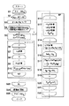
この逆投影処理について、図2に示す幾何図、および図3に示すフロー図を用いて説明する。
【0060】
なお、既出の符号および図より明らかな符号の説明については省略する。
【0061】
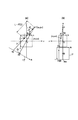
図2(a)および(b)は、被検体4に固定した座標x,y,zで見たX線焦点Fと検出面17の位置である。Fの回転角をφとする。
【0062】
再構成する体積の各ボクセルをi,j,kで番号づけ、ボクセルサイズを△x,△y,△zとする。
【0063】
ここで、△yは△xと等しく設定し、△zも△xと等しくすることが好ましい。
【0064】
次に、図3において、ステップS1で360°分のφループとなり、ステップS2でFのx,y座標xF,yFが計算され、
xF=FCD・sinφ ・・・(3)
yF=FCD・cosφ ・・・(4)
FCD:焦点、回転中心間距離
ステップS3,S4でボクセルj,iのループに入り、ステップS5でnij,△mij, L2を求める。
【0065】
nij,mijk:ボクセルi,j,kにBPされるチャンネル番号
△mij:kが1増加したときのmijkの増分
1/L2:BPウエイト
x=(i−ic)・△x ・・・(5)
y=(jc−j)・△y ・・・(6)
△x,△y,△z:ボクセルサイズ
φ'=arctan((xF−x)/(yF−y)) ・・・(7)
θ=φ−φ' ・・・(8)
nij=nc+FDD・tanθ/d ・・・(9)
L2=((xF−x)2+(yF−y)2)/FCD2 ・・・(10)
△mij=FDD/(√(L2)・FCD・cosθ)・△z/d ・・・(11)
d:チャンネル間隔
FDD:焦点、検出面間距離
ステップS5で、さらにmijkの初期値を設定する。
【0066】
mijk=mc+(ks−kc)・△mij ・・・(12)
次に、ステップS6でkループに入り、ステップS7でボクセルi,j,kへのたし込みを行なう。
【0067】

【0068】
次に、ステップS8で、次のkのためにmijkを更新する。
【0069】
mijk=mijk+△mij ・・・(14)
ステップS9,S10,S11でk,i,jについて繰り返すことで体積全体についてたし込み、ステップS12でφを繰り返し一つの体積に逆投影をたし込んで逆投影処理が終わり、体積の3次元像ができる。
【0070】
以上の逆投影処理の説明では、説明をわかり易くするため最速な計算式になっておらず、式はループ外に出せる部分を多く含んでいる。
【0071】
上述したように、本実施の形態によるCTスキャナでは、回転軸12方向のボクセルのループ、すなわちkループを最内としているので、対応チャンネルnij,mijk(あるいは△mij)の計算をkループ内で共通にできるため、前述した従来のように、kループをi,jループの外側にする場合よりも計算に無駄が無くなる。
【0072】
また、データを収集した順に他のデータを待つことなく再構成できるため、再構成速度を上げることが可能となる。
【0073】
さらに、撮影面11からの傾斜に従って逆投影しているため、回転軸12方向の分解能を上げることが可能となる。
【0074】
(第1の実施の形態の変形例)
BPウエイトは、1/L2以外にさらに図4で示すように、回転角によるウエイトw(φ)を掛けるようにしてもよい。
【0075】
この場合、360°+2αの回転の間、データ収集を行なう。このウェイトを掛けると、360°の回転の前後が平均されるため、撮影中に被検体4が回転テーブル5上で微動しても偽像が生じ難くなる。
【0076】
ウェイトw(φ)は、傾斜部が曲線でもよい。すなわち、360°ずらしたものと加算した時1になるようになっていればよい。
【0077】
(第2の実施の形態)
本実施の形態によるCTスキャナのシステム構成は前記図1と同様であり、体積BP部16bによる逆投影処理の方法のみが異なっている。
【0078】
従ってここでは、本実施の形態のCTスキャナの逆投影処理(作用)について、図5および図6に示す幾何図、および図7に示すフロー図を用いて説明する。
【0079】
なお、既出の符号および図より明らかな符号の説明については省略する。
【0080】
図5は、被検体4に固定した座標x,y,zで見たX線焦点Fと検出面17の位置である。Fの回転角をφとする。
【0081】
図6も同様で、再構成する体積の各ボクセルをi,j,kで番号づけ、ボクセルサイズを△x,△y,△zとする(△y=△x)。
【0082】
次に、図7において、ステップS1で360°分の投影データpは90°分ずつのクオータに分けられ、ステップS2で最初の90°分のφc(計算回転角)ループとなり、ステップS3でデータ収集回転角φを計算する.
φ=φc+nq・π/2 ・・・(15)
nq:クオータ番号
ステップS4で、φが収集中のφであるか判定して頭だし、あるいは終了を行なう。
【0083】
ステップS5で、Fのx,y座標xF,yFが計算される。
【0084】
xF=FCD・sinφc ・・・(16)
yF=FCD・cosφc ・・・(17)
次に、ステップS6〜ステップS11でセンタリングを行なう。
【0085】
図5において、センタリングは検出面17上のデータをxz平面上のpqマトリックスに逆投影する処理である。
【0086】
ステップS6でpループに入り、ステップS7でnpを求める。
【0087】
xo=(p−pc)・cp ・・・(18)
x1=xo・cosφc ・・・(19)
mag1=FDD/√((xF−xo)2+yF2−x12)) ・・・(20)
np=nc+x1・mag1/d ・・・(21)
np,mpq:マトリックスp,qにBPされるチャンネル番号
cp,cq:センタリングピッチ
次に、ステップS8でqループに入り、ステップS9でmpq、ステップS10でセンタリングデータpc(p,q)を求める。
【0088】
mpq=mc+(q−qc)・cq・mag1/d ・・・(22)
pc(p,q)=pφ(np,mpq) ・・・(23)
ここで、npとmpqは一般に整数とならないので、補間計算を行なう。
【0089】
次に、ステップS11で、次のq,pを繰り返す。
【0090】
次に、ステップS12〜ステップS22でBPを行なう。
【0091】
図6において、ステップS12でjループに入り、ステップS13でpoj、△pj、△qjを求める。
【0092】
mag2=yF/(yF+(j−jc)・△y) ・・・(24)
poj=pc+(xF−mag2・(xF+ic・△x))/cp ・・(25)
△pj=mag2・△x/cp ・・・(26)
△qj=mag2・△y/cp ・・・(27)
pij,qjk:ボクセルi,j,kにBPされるマトリックス番号
△pj:iが1増加したときのpijの増分
△qj:kが1増加したときのqjkの増分
ステップS13で、さらにpijの初期値を設定する。
【0093】
pij=poj ・・・(28)
次に、Sステップ14でiループに入り、ステップS15でL2を計算する。
【0094】
x=(i−ic)・△x ・・・(29)
y=(jc−j)・△y ・・・(30)
L2=((xF−x)2+(yF−y)2)/FCD2 ・・・(31)
ステップS15で、さらにqjkの初期値を設定する。
【0095】
qjk=qc+(ks−kc)・△qj ・・・(32)
次に、ステップS16でkループに入り、ステップS17でボクセルi,j,kへのたし込みを行なう。
【0096】
【0097】
次に、ステップS18で、次のkのためにqjkを更新する。
【0098】
qjk=qjk+△qj ・・・(34)
ステップS19でkループを繰り返し、ステップS20で次のiのためにpijを更新する。
【0099】
pij=pij+△Pj (35)
ステップS21,S22でi,jについて繰り返すことで体積全体についてたし込み、ステップS23でφcを繰り返し一つの体積に逆投影をだし込んで行く。
【0100】
ステップS24で画像を90度回転し、ステップS25でクオータについて繰り返して逆投影処理が終わり、体積の3次元像ができる。
【0101】
以上の逆投影処理の説明では、説明をわかり易くするため最速な計算式になっておらず、式はループ外に出せる部分を多く含んでいる。
【0102】
上述したように、本実施の形態によるCTスキャナでは、まず、各回転位置φで検出面17上のデータをxz平面に逆投影してセンタリングデータpcを求めると、pcはボクセルの一つの面ik平面に平行な面上で等間隔で得られるため、ik面への逆投影計算(具体的には、pij,qjkの計算)を著しく簡略化することができ、再構成速度を上げることが可能となる。
【0103】
また、前述した第1の実施の形態と同様に、回転軸12方向のボクセルのループ、すなわちkループを最内としているので、対応チャンネルpij,qjk(あるいは△qj)の計算をkループ内で共通にできるため、前述した従来のように、kループをi,jループの外側にする場合よりも計算に無駄が無くなり、再構成速度を上げることが可能となる。
【0104】
さらに、データを収集した順に他のデータを待つことなく再構成できるため、再構成速度を上げることが可能となる。
【0105】
さらにまた、撮影面11からの傾斜に従って逆投影しているため、回転軸12方向の分解能を上げることが可能となる。
【0106】
(第2の実施の形態の変形例)
前述した第1の実施の形態の変形例と同様に、BPウエイトは、1/L2以外にさらに図4で示すように、回転角によるウエイトw(φ)を掛けるようにしてもよい。この場合にも、同様の作用効果を得ることができる。
【0107】
第2の実施の形態において、体積のk方向がij方向と比較して同等のサイズの場合には、iループをkループの内側にするようにしてもよい。この場合、式(33)は略計算でなく1行目の計算を行なう。
【0108】
(第3の実施の形態)
本実施の形態によるCTスキャナのシステム構成は前記第2の実施の形態と同様であり、透過像収集時の機構動作と体積BP部16bによる逆投影処理の方法のみが異なっている。
【0109】
従ってここでは、本実施の形態のCTスキャナの透過像収集時の作用と、逆投影処理(作用)について、図7に示すフロー図を用いて説明する。
【0110】
本実施の形態の場合には、断層撮影を開始すると、回転テーブル5が回転と同時に昇降され(ヘリカルスキャン)、この間に透過像が収集され、360度以上の方向の透過データから体積の3次元像が再構成され、表示部10に表示される。
【0111】
また、本実施の形態の体積BPは、前述した第2の実施の形態の場合とほぼ同様であり、図7に示すフロー図、および式(15)〜(35)を用いて説明する。
【0112】
すなわち、前述した第2の実施の形態の場合と異なる点は、kcが定数でなくφの関数であること、および式(33)が異なることである。
【0113】
【0114】
まず、式(36)でkc(φ)は、回転角φの時の撮影面11が横切るマトリックスのk位置である。
【0115】
この式で、zpは1回転中に昇降する高さ(ヘリカルビッチ)で、△zは高さ方向のボクセルサイズ、φOはk=0を横切る時の回転角である。
【0116】
図8(a)で、wφ(z)は回転角φの時のz方向のボクセルのBPのウェイトで半値幅zpの台形状となる。
【0117】
この台形の斜面においては、360°異なるφからのBPが合成される(点線)。
【0118】
wφ(z)をk目盛に変更したウエイトがwφ(k)で、図8(b)に示す中心がkc(φ)、半値幅zp/△zの台形である。
【0119】
kでのzp/△zは回転角で、360°に相当する。
【0120】
ここで、斜面の半長kαは角度αと、
kα=Zp/△z・α/2π ・・・(37)
の関係があり、補間合成する角度半幅αを設定するとkαが決まる。
【0121】
式(33')においては、BPウェイトにwφ(k)を用いるため、ヘリカルスキャンを行なった場合に、φについて連続してBPを行なっても、各ボクセルに360°分のBPがなされる。
【0122】
上述したように、本実施の形態によるCTスキャナでは、前述した第2の実施の形態と同様に、再構成速度を上げること、および回転軸12方向の分解能を上げることが可能となる。
【0123】
また、ヘリカルスキャンで効率よく、かつ撮影面11からのビームの傾斜を大きくせずに撮影できるため、回転軸12方向に広くかつ高品質の3次元像を得ることができる。
【0124】
さらに、ヘリカルスキャンで回転、昇降を一定速度で滑らかに広い範囲をスキャンできるため、被検体4に加速度がかからず、動き易い被検体4でも高品質の画像を得ることができる。
【0125】
また、台形のウェイトwφ(k)を掛けてBPしているので、360°の回転の前後が平均されるため、撮影中に被検体4が動いても偽像が生じ難くなる。
【0126】
(第3の実施の形態の変形例)
ウエイトwφ(k)は、図8(c)に示すように、傾斜部が曲線であってもよい。すなわち、zp/△zずらしたもの(点線)と加算した時に1になるようになっていればよい。
【0127】
(第4の実施の形態)
本実施の形態によるCTスキャナのシステム構成は前記第3の実施の形態とほぼ同様であり、LOG変換部15と再構成部16との間に窓関数掛け部を備えている点、および回転中心が上から見てX線ビーム2の中心からずれて設定されている点が異なっている。
【0128】
図9は、回転中心CとX線ビーム2との位置関係を示す概要図である。
【0129】
これは、回転テーブル5をずらして設定して、被検体4をX線ビーム2から片側にはみ出させて載置し、大きな被検体4も撮影可能としたCTスキャナであり、この撮影法はオフセットスキャンと呼ばれる。
【0130】
本実施の形態によるCTスキャナにおける作用は、前記第3の実施の形態と同様であり、LOG変換後の投影データpφ(n,m)に対して、図10に示すような窓関数w(n)を掛ける点のみが異なっている。
【0131】
窓関数w(n)は中心ch,ncで、0.5でここを中心に傾斜しており、傾斜領域の外側の一方は0もう一方は1である。
【0132】
再構成部16は、前記第3の実施の形態と同様に再構成を行なう。
【0133】
上述したように、本実施の形態によるCTスキャナでは、オフセットスキャンの場合でも、データ列を再編成(パラレルデータヘの変換等)することが不要となるため、高速で再構成することができ、さらに中心chを挟んで滑らかなウエイトが掛かるため、投影データの急激な変化が避けられ、偽像(リング状)の少ない3次元像を得ることができる。
【0134】
さらに、ヘリカルスキャンを行ないながらオフセットスキャンを実施することができ、前述した第3の実施の形態と同様の効果を得ることができるのに加えて、大きな被検体4に対応できるCTスキャナを実現することが可能となる。
【0135】
(第4の実施の形態の変形例)
第4の実施の形態によるオフセットスキャンは、前述した第1または第2の実施の形態に対して適用することもできる。
【0136】
また、窓関数w(n)は傾斜部が曲線であってもよい。すなわち、中心chで0.5、軸に直交する左右側に傾きが対称な0から1まで変化する傾斜部を有し、傾斜部の外は片側が0逆側が1であればよい。
【0137】
(第5の実施の形態)
図11は、本実施の形態によるCTスキャナのシステム構成例を示す概要図で、前記第1の実施の形態とほぼ同様であり、空気補正部14とLOG変換部15との間に散乱線補正部19を備えている点、およびX線ビーム2を撮影面11を挟んだ薄厚コーン状に制限する可動のコリメータ18を備えている点が異なっている。
【0138】
本実施の形態によるCTスキャナにおける作用は、前記第1の実施の形態と同様であり、断層撮影時にX線ビーム2を薄厚コーン状に制限する点と、空気補正後のデータh(n,m)に対して散乱線補正を行なう点が異なっている。
【0139】
図12は、散乱線補正の内容を説明するための図である。
【0140】
図12は、検出面17上のデータh(n,m)を示している。
【0141】
X線ビーム2の照射部20以外はコリメータ18で遮られる部分で、被検体4等からの散乱線のみ検出している。
【0142】
照射部20内のデータh(n,m)に対して、散乱線補正
【0143】
ここでは、h(n,m)に近い上下の2チャンネルを1次補間して散乱線を求め、減算している。
【0144】
上述したように、本実施の形態によるCTスキャナでは、散乱線測定の専用の検出器を用いることなく、2次元検出器のコリメータ18で遮られる部分のデータを用いて散乱線補正をすることができる。
【0145】
また、専用の検出器に対して、2次元検出器は全チャンネルが一度に製造されるため、特性が均質である。
【0146】
さらに、測定点に近い位置で、同時にしかも均質な条件で散乱線が測定できるため、正確に補正を行なうことが可能となる。
【0147】
(第5の実施の形態の変形例)
第5の実施の形態において、補正を行なうに当たっては、2チャンネルのデータでなく、もっと多数のチャンネルデータを用いてもよく、1次補間でなくてもよい。
【0148】
この多数のチャンネルデータを用いることにより、統計精度を上げることが可能となる。
【0149】
第5の実施の形態における散乱線補正は、前記第1の実施の形態に付加するだけでなく、前記第2乃至第4の実施の形態に対しても付加することができ、さらに単独で図13に示すような従来の2次元検出器を用いるCTスキャナに対しても付加することができる.
(第6の実施の形態)
本実施の形態によるCTスキャナのシステム構成は前記第1の実施の形態とほぼ同様であり、やわらかな変形し易い被検体4の撮影に適用される点が異なっている。
【0150】
本実施の形態の場合、被検体4をテーブル5に設定し、準備回転として、滑らかな一定速度の回転を行なわせ、十分に被検体4を安定させた後に、断層撮影を開始する。
【0151】
装置は、そのまま同じ回転速度を保ったままX線をONさせ、透過像を収集して3次元像を作成する。
【0152】
ヘリカルスキャンの場合は、同様に準備回転を行なわせておき、断層撮影開始時に昇降を徐々に開始させて透過像を収集開始する。
【0153】
また、準備回転の時間が短くてよい場合には、準備昇降をいっしょに行なってもよい。
【0154】
上述したように、本実施の形態によるCTスキャナでは、回転始動時に生じた被検体4の動きを一定速度回転を続けて終息させ、その後に回転速度を変えずに撮影するため、変形し易い被検体4でも動きを終息させて撮影でき、高品質な3次元像を得ることができる。
【0155】
(第7の実施の形態)
本実施の形態によるCTスキャナのシステム構成は前記第1の実施の形態とほぼ同様であり、フィルタ関数の自動選択を行なう点が異なっている。
【0156】
すなわち、データ処理部9は、フィルタ掛け前のデータ(pあるいはh)の信号ノイズ比(平均)を計算して、フィルタ関数を自動選択する。
【0157】
信号ノイズ比は、低周波数成分を信号、高周波数成分をノイズとして、その比である信号/ノイズを求める。
【0158】
信号ノイズ比の小さな場合、フィルタ関数は低いカットオフ周波数のものを選択して、空間分解能を少し低下させる代りに画像ノイズを少なくさせる。
【0159】
上述したように、本実施の形態によるCTスキャナでは、撮影倍率や管電圧、管電流、スキャン時間等の撮影条件を任意に変更しても、透過データの信号ノイズ比でフィルタ関数を選択するため、画像ノイズと空間分解能との関係が最適な断面像を得ることができる。
【0160】
【発明の効果】
以上説明したように、本発明のコンピュータ断層撮影方法および装置によれば、撮影の高速化あるいは画像の高品質化に寄与することが可能となる。
【図面の簡単な説明】
【図1】本発明によるCTスキャナの第1の実施の形態を示す概要図。
【図2】同第1の実施の形態のCTスキャナにおける作用を説明するための幾何図。
【図3】同第1の実施の形態のCTスキャナにおける作用を説明するためのフロー図。
【図4】本発明によるCTスキャナの第1の実施の形態の変形例を示す図。
【図5】本発明の第2の実施の形態のCTスキャナにおける作用を説明するための幾何図。
【図6】本発明の第2の実施の形態のCTスキャナにおける作用を説明するための幾何図。
【図7】本発明の第2の実施の形態および第3の実施の形態のCTスキャナにおける作用を説明するためのフロー図。
【図8】本発明の第3の実施の形態およびその変形例のCTスキャナにおける作用を説明するための図。
【図9】本発明によるCTスキャナの第4の実施の形態を示す部分概要図。
【図10】同第4の実施の形態のCTスキャナにおける作用を説明するための図。
【図11】本発明によるCTスキャナの第5の実施の形態を示す部分概要図。
【図12】同第5の実施の形態のCTスキャナにおける作用を説明するための図。
【図13】従来の高分解能型CTスキャナのシステム構成例を示す概要図。
【符号の説明】
1…X線管
2…X線ビーム
3…放射線検出器
4…被検体
5…回転テーブル
6…回転・昇降機構
7…シフト機構
8…機構制御部
9…データ処理部
10…表示部
11…撮影面
12…回転軸
13…X線制御部
17…検出面
18…コリメータ
19…散乱線補正部
20…照射部。[0001]
BACKGROUND OF THE INVENTION
The present invention relates to a computer tomography method and apparatus among non-destructive inspection apparatuses, and more particularly to a computer tomography method and apparatus capable of contributing to high-speed imaging or high image quality.
[0002]
[Prior art]
In recent years, high-resolution industrial computer tomography apparatuses (hereinafter referred to as CT scanners) have been manufactured for the purpose of inspecting small electronic components and the like with high resolution.
[0003]
FIG. 13 is a schematic diagram showing a system configuration example of this type of conventional high-resolution CT scanner, in which both a transmission image and a cross-sectional image are obtained.
[0004]
In FIG. 13, an
[0005]
The transmitted image can be displayed as a moving image in real time, or can be added by the
[0006]
When the rotary table 105 and the
[0007]
When taking a cross-sectional image, a large number of transmission images are obtained while rotating the
[0008]
The multiple transmission images are processed by the
[0009]
As the reconstruction method, for example, a filter-corrected back projection method (FBP method) shown in, for example, “CT scanner” (Yoshinori Iwai edition: Corona) is used.
[0010]
The cross-sectional image position of the
[0011]
Further, there is a method of performing a helical scan and obtaining a plurality of cross-sectional images substantially parallel to the imaging
[0012]
The reconstruction method at this time is described in the following literature as an application of the FBP method.
[0013]
(Reference 1) “CT System” Toshiba Corp. Hiroshi Arata, Shinjiro Nambu, “Japanese Patent Laid-Open No. 4-224736”
In the first reconstruction method here, since the transmission image plane passing outside the
[0014]
This second reconstruction method can be said to be a method (Feldkamp method) described in the following document applied to a helical scan.
[0015]
(Reference 2) “Practica1 cone-beam algorithm” L. A. Fe1dkamp, L. C. Davis, and J.W. Kress J.0pt.Soc.Am./Vol.1,No.6,pp.612-619/June1984
[0016]
[Problems to be solved by the invention]
By the way, recently, there is a strong demand for examinations using a CT scanner, and the types of examination objects and examination contents are expanding. For this reason, there is a tendency that the demand for higher image quality and the demand for higher imaging speed are increasing.
[0017]
However, when a plurality of cross-sectional images are obtained by a single scan using the cone-
[0018]
Further, the above-described
[0019]
On the other hand, the above-described conventional high-resolution CT scanner has a feature that a high-resolution image can be obtained by bringing the
[0020]
In addition, the
[0021]
Furthermore, depending on the arbitrarily selected shooting conditions, the reconstruction filter function may be inappropriate, resulting in a noisy image. In such a case, the filter function is selected again and reconstructed.
[0022]
An object of the present invention is to provide a computer tomography method and apparatus capable of contributing to high-speed imaging or high image quality.
[0023]
[Means for Solving the Problems]
In order to achieve the above object, a computed tomography apparatus according to a first aspect of the present invention provides a radiation source that emits a radiation beam and a radiation detection that detects the radiation beam from the radiation source with two-dimensional spatial resolution. A rotation means for relatively rotating the subject within the radiation beam, and a translation means for relatively moving the subject within the radiation beam in the axial direction of the rotation. The rotation by the rotation means and the translation means In a computed tomography device that collects transmission data while performing the relative movement by almost simultaneously,
Two-dimensional transmission data from multiple directions of the subject obtained by the radiation detector during rotation by the rotation meansOn the other hand, the rotation axis position is 0.5, and the right and left sides orthogonal to the rotation axis have an inclined portion that changes from 0 to 1 in which the inclination is symmetric. A window function multiplication unit for multiplying the window function, and two-dimensional transmission data multiplied by the window function3D imageA volume backprojection unit that backprojects to a volume element;Reconstructing means for creating a three-dimensional image of the subject.
[0026]
Therefore, in the computer tomography apparatus of the invention corresponding to claim 1, for the purpose of imaging a large subject, a rotation center is set at the end of the radiation beam detected by the radiation detector, Transmission data is obtained by protruding the subject outside the beam. ( Offset scan ) In some cases, by multiplying the window function, sudden changes in the projection data can be avoided. ( Ring shape ) Can be obtained. Also reorganize data columns ( Conversion to parallel data, etc. ) Can be reconfigured at high speed..
[0028]
Also, Claims1In the computed tomography apparatus according to the invention, a three-dimensional image over a wide area in the direction of the rotation axis of the subject can be obtained at a time.
[0029]
Furthermore, in the invention corresponding to claim 2, in the computed tomography apparatus of the invention corresponding to claim 1,The volume back projection unit back projects the two-dimensional transmission data multiplied by the window function onto a centering surface substantially parallel to one surface substantially parallel to the rotation axis of the volume element of the three-dimensional image. Is projected back to each volume element for each set of volume elements approximately parallel to the centering plane.
[0030]
Therefore, the claims2In the computer tomography apparatus of the invention corresponding toSince the second back projection becomes back projection between parallel planes, the calculation time of the back projection coefficient can be shortened, and reconstruction can be performed at high speed..
[0031]
Meanwhile, claims3The computer tomography apparatus according to the invention corresponds to a collimator that restricts the radiation beam to a fan beam along a plane of rotation, and the transmission data of the passage blocked by the collimator is used to scatter the transmission data that is not blocked. And a scattered radiation correcting means for correcting radiation.
[0032]
Therefore, the claims3In the computed tomography apparatus according to the invention, the intensity of only the scattered radiation is obtained from the transmission data of the blocked passage, and the transmission data of the blocked passage close to the two-dimensional position of the transmission data is obtained from the transmission data that is not blocked. By subtracting the transmission data, the scattered radiation can be corrected, and a high-quality cross-sectional image can be obtained.
[0033]
Meanwhile, claims4In the computer tomography apparatus according to the invention, the reconstruction unit selects a filter function based on a signal-to-noise ratio of the transmission data, and performs a filter correction back projection to create a three-dimensional image. Computer tomography equipment.
[0034]
Therefore, the claims4In the computed tomography apparatus according to the invention, the filter function is selected based on the signal-to-noise ratio of the transmission data even if the imaging conditions such as the imaging magnification, the tube voltage, the tube current, and the scan time are arbitrarily changed. A cross-sectional image in which the relationship between noise and spatial resolution is optimal can be obtained.
[0037]
DETAILED DESCRIPTION OF THE INVENTION
Hereinafter, embodiments of the present invention will be described in detail with reference to the drawings.
[0038]
(First embodiment)
FIG. 1 is a schematic diagram showing a system configuration example of a CT scanner according to the present embodiment.
[0039]
In FIG. 1, as an
[0040]
The
[0041]
The
[0042]
Further, the
[0043]
Although not shown, the mechanism portion is surrounded by X-ray shielding.
[0044]
On the other hand, as other components, a
[0045]
The
[0046]
The operator uses the
[0047]
The
[0048]
Next, the operation of the CT scanner configured as described above according to the present embodiment will be described.
[0049]
In FIG. 1, when obtaining a transmission image, the operator places the subject 4 on the table 5, sets the tube voltage and tube current, turns on the X-ray, and displays the transmission image on the
[0050]
In the case of a three-dimensional image, the
[0051]
This can also be done while looking at the transmission image.
[0052]
When tomography starts, the rotary table 5 rotates, and during this time, a transmission image is collected by the data processing unit 9.From transmission data in the vicinity of the
[0053]
First, the transmission image is corrected by the
[0054]
h = (d-doff) / (da-doff) (1)
Here, doff is data when the X-ray is OFF.
[0055]
Next, each channel is logarithmically converted by the
[0056]
p = LOG (1 / h) (2)
The projection data of the n and m channels at the rotation angle φ is described as pφ (n, m), and then a high frequency enhancement filter is applied in the n direction along the
[0057]
This is done by performing a Fourier transform in the n direction, applying a filter function that is approximately proportional to the frequency in the frequency space, and returning it by an inverse Fourier transform.
[0058]
Next, the volume BP unit 16b performs back projection on each volume element (voxel).
[0059]
This back projection processing will be described with reference to the geometric diagram shown in FIG. 2 and the flowchart shown in FIG.
[0060]
Note that description of the above-described reference signs and signs that are obvious from the drawings is omitted.
[0061]
FIGS. 2A and 2B show the positions of the X-ray focal point F and the
[0062]
Each voxel of the volume to be reconstructed is numbered by i, j, k, and the voxel size is Δx, Δy, Δz.
[0063]
Here, Δy is preferably set equal to Δx, and Δz is also preferably equal to Δx.
[0064]
Next, in FIG. 3, a φ loop for 360 ° is obtained in step S1, and x, y coordinates xF, yF of F are calculated in step S2,
xF = FCD · sinφ (3)
yF = FCD · cosφ (4)
FCD: Distance between focal point and center of rotation
In steps S3 and S4, the loop of voxels j and i is entered. In step S5, nij, Δmij, L2Ask for.
[0065]
nij, mijk: Channel number BP to voxel i, j, k
△ mij: increment of mijk when k increases by 1
1 / L2: BP weight
x = (i−ic) · Δx (5)
y = (jc−j) · Δy (6)
△ x, △ y, △ z: Voxel size
φ ′ = arctan ((xF−x) / (yF−y)) (7)
θ = φ−φ ′ (8)
nij = nc + FDD.tan.theta. / d (9)
L2= ((XF-x)2+ (YF-y)2) / FCD2 ... (10)
Δmij = FDD / (√ (L2) ・ FCD ・ cosθ) ・ △ z / d (11)
d: Channel spacing
FDD: Focus, distance between detection surfaces
In step S5, an initial value of mijk is further set.
[0066]
mijk = mc + (ks−kc) · Δmij (12)
Next, in step S6, the k loop is entered, and in step S7, addition to the voxels i, j, k is performed.
[0067]
[0068]
Next, in step S8, mijk is updated for the next k.
[0069]
mijk = mijk + Δmij (14)
Steps S9, S10, and S11 are repeated for k, i, and j, and the entire volume is added. In step S12, φ is repeated and backprojection is added to one volume, and the backprojection process is completed, and the volume is three-dimensional. I can make an image.
[0070]
In the above description of the backprojection process, the formula is not the fastest for easy understanding, and the formula includes many parts that can be put out of the loop.
[0071]
As described above, in the CT scanner according to the present embodiment, the loop of voxels in the direction of the
[0072]
In addition, since the data can be reconfigured without waiting for other data in the order in which the data is collected, the reconfiguration speed can be increased.
[0073]
Furthermore, since the back projection is performed according to the inclination from the
[0074]
(Modification of the first embodiment)
BP weight is 1 / L2In addition to this, as shown in FIG. 4, a weight w (φ) depending on the rotation angle may be multiplied.
[0075]
In this case, data collection is performed during 360 ° + 2α rotation. When this weight is applied, before and after 360 ° rotation is averaged, even if the subject 4 moves slightly on the rotary table 5 during imaging, a false image is less likely to occur.
[0076]
The weight w (φ) may have a curved slope portion. That is, it is only necessary to be 1 when added with the one shifted by 360 °.
[0077]
(Second Embodiment)
The system configuration of the CT scanner according to the present embodiment is the same as that shown in FIG. 1, and only the method of back projection processing by the volume BP unit 16b is different.
[0078]
Therefore, here, the back projection processing (action) of the CT scanner of this embodiment will be described with reference to the geometric diagrams shown in FIGS. 5 and 6 and the flowchart shown in FIG.
[0079]
Note that description of the above-described reference signs and signs that are obvious from the drawings is omitted.
[0080]
FIG. 5 shows the positions of the X-ray focal point F and the
[0081]
Similarly in FIG. 6, each voxel of the volume to be reconstructed is numbered by i, j, k, and the voxel sizes are set as Δx, Δy, Δz (Δy = Δx).
[0082]
Next, in FIG. 7, the projection data p for 360 ° in step S1 is divided into quarters for 90 °, and in step S2, the first 90 ° φc (calculation rotation angle) loop is formed. Calculate the collection rotation angle φ.
φ = φc + nq · π / 2 (15)
nq: quota number
In step S4, it is determined whether or not φ is the φ being collected, and the head is cued or terminated.
[0083]
In step S5, the x and y coordinates xF and yF of F are calculated.
[0084]
xF = FCD · sinφc (16)
yF = FCD · cosφc (17)
Next, centering is performed in steps S6 to S11.
[0085]
In FIG. 5, centering is a process of back-projecting data on the
[0086]
In step S6, a p-loop is entered, and np is obtained in step S7.
[0087]
xo = (p−pc) · cp (18)
x1 = xo ・ cosφc (19)
mag1 = FDD / √ ((xF−xo)2+ YF2-X12)) ... (20)
np = nc + x1 · mag1 / d (21)
np, mpq: Channel numbers BP to matrix p, q
cp, cq: Centering pitch
Next, a q loop is entered at step S8, mpq is obtained at step S9, and centering data pc (p, q) is obtained at step S10.
[0088]
mpq = mc + (q-qc) .cq.mag1 / d (22)
pc (p, q) = pφ (np, mpq) (23)
Here, since np and mpq are generally not integers, interpolation calculation is performed.
[0089]
Next, in step S11, the following q and p are repeated.
[0090]
Next, BP is performed in steps S12 to S22.
[0091]
In FIG. 6, the j loop is entered in step S12, and poj, Δpj, and Δqj are obtained in step S13.
[0092]
mag2 = yF / (yF + (j−jc) · Δy) (24)
poj = pc + (xF−mag2 · (xF + ic · Δx)) / cp (25)
Δpj = mag2 · Δx / cp (26)
Δqj = mag2 · Δy / cp (27)
pij, qjk: matrix number BP to voxel i, j, k
Δpj: increment of pij when i increases by 1
Δqj: increment of qjk when k increases by 1
In step S13, an initial value of pij is further set.
[0093]
pij = poj (28)
Next, in step S14, the i loop is entered, and in step S15, L2Calculate
[0094]
x = (i−ic) · Δx (29)
y = (jc−j) · Δy (30)
L2= ((XF-x)2+ (YF-y)2) / FCD2 ... (31)
In step S15, an initial value of qjk is further set.
[0095]
qjk = qc + (ks−kc) · Δqj (32)
Next, in step S16, the k loop is entered, and in step S17, addition to the voxels i, j, k is performed.
[0096]
[0097]
Next, in step S18, qjk is updated for the next k.
[0098]
qjk = qjk + Δqj (34)
The k loop is repeated in step S19, and pij is updated for the next i in step S20.
[0099]
pij = pij + △ Pj (35)
In steps S21 and S22, the entire volume is added by repeating i, j, and φc is repeated in step S23 to add back projection to one volume.
[0100]
In step S24, the image is rotated 90 degrees, and in step S25, the quota is repeated to complete the back projection process, and a three-dimensional image of the volume is obtained.
[0101]
In the above description of the backprojection process, the formula is not the fastest for easy understanding, and the formula includes many parts that can be put out of the loop.
[0102]
As described above, in the CT scanner according to the present embodiment, first, when the centering data pc is obtained by back projecting the data on the
[0103]
Further, similarly to the first embodiment described above, since the loop of voxels in the direction of the
[0104]
Furthermore, since the data can be reconfigured without waiting for other data in the order in which the data is collected, the reconfiguration speed can be increased.
[0105]
Furthermore, since the back projection is performed according to the inclination from the
[0106]
(Modification of the second embodiment)
Similar to the modification of the first embodiment described above, the BP weight is 1 / L.2In addition to this, as shown in FIG. 4, a weight w (φ) depending on the rotation angle may be multiplied. Also in this case, the same effect can be obtained.
[0107]
In the second embodiment, when the volume k direction is the same size as the ij direction, the i loop may be located inside the k loop. In this case, equation (33) is not an approximate calculation, but the first row is calculated.
[0108]
(Third embodiment)
The system configuration of the CT scanner according to this embodiment is the same as that of the second embodiment, and only the mechanism operation at the time of transmission image collection and the back projection processing method by the volume BP unit 16b are different.
[0109]
Therefore, here, the operation at the time of transmission image collection and the back projection processing (operation) of the CT scanner of the present embodiment will be described with reference to the flowchart shown in FIG.
[0110]
In the case of this embodiment, when tomography is started, the rotary table 5 is moved up and down at the same time as the rotation (helical scan), and transmission images are collected during this time, and the three-dimensional volume is obtained from transmission data in directions of 360 degrees or more. The image is reconstructed and displayed on the
[0111]
The volume BP of the present embodiment is substantially the same as that of the second embodiment described above, and will be described using the flowchart shown in FIG. 7 and equations (15) to (35).
[0112]
That is, the difference from the case of the second embodiment described above is that kc is not a constant but a function of φ, and equation (33) is different.
[0113]
[0114]
First, in equation (36), kc (φ) is the k position of the matrix that the
[0115]
In this equation, zp is the height (helical bitch) that moves up and down during one rotation, Δz is the voxel size in the height direction, and φO is the rotation angle when crossing k = 0.
[0116]
In FIG. 8A, wφ (z) is a weight of the BP of the voxel in the z direction at the rotation angle φ and has a trapezoidal shape with a half width zp.
[0117]
On this trapezoidal slope, BP from φ different 360 ° is synthesized (dotted line).
[0118]
The weight obtained by changing wφ (z) to k scale is wφ (k), and the center shown in FIG. 8B is a trapezoid with kc (φ) and half width zp / Δz.
[0119]
zp / Δz at k is a rotation angle and corresponds to 360 °.
[0120]
Here, the half length kα of the slope is an angle α,
kα = Zp / Δz · α / 2π (37)
Therefore, kα is determined by setting the angle half width α to be interpolated.
[0121]
In Expression (33 ′), wφ (k) is used as the BP weight. Therefore, when helical scanning is performed, BP corresponding to 360 ° is applied to each voxel even if BP is continuously performed for φ.
[0122]
As described above, in the CT scanner according to the present embodiment, it is possible to increase the reconstruction speed and the resolution in the direction of the
[0123]
In addition, since the image can be taken efficiently by the helical scan without increasing the inclination of the beam from the
[0124]
Furthermore, since a wide range can be scanned smoothly at a constant speed of rotation and elevation by helical scanning, the
[0125]
In addition, since the BP is multiplied by the trapezoidal weight wφ (k), before and after 360 ° rotation is averaged, even if the subject 4 moves during imaging, a false image is hardly generated.
[0126]
(Modification of the third embodiment)
As shown in FIG. 8C, the weight wφ (k) may have a curved slope. That is, it is only necessary to be 1 when added with the one shifted by zp / Δz (dotted line).
[0127]
(Fourth embodiment)
The system configuration of the CT scanner according to this embodiment is almost the same as that of the third embodiment, and is provided with a window function multiplying section between the
[0128]
FIG. 9 is a schematic diagram showing the positional relationship between the rotation center C and the
[0129]
This is a CT scanner in which the rotating table 5 is set to be shifted and the
[0130]
The operation of the CT scanner according to the present embodiment is the same as that of the third embodiment, and a window function w (n as shown in FIG. 10 is applied to the projection data pφ (n, m) after LOG conversion. ) Is only different.
[0131]
The window function w (n) is center ch, nc, and is inclined about 0.5 at the center. One outside the inclined area is 0, and the other is 1.
[0132]
The
[0133]
As described above, in the CT scanner according to the present embodiment, it is not necessary to reorganize the data string (conversion to parallel data, etc.) even in the case of offset scanning, and can be reconstructed at high speed. Since a smooth weight is applied across the center ch, a sudden change in projection data can be avoided, and a three-dimensional image with few false images (ring-shaped) can be obtained.
[0134]
Furthermore, an offset scan can be performed while performing a helical scan, and in addition to obtaining the same effects as those of the third embodiment described above, a CT scanner capable of handling a
[0135]
(Modification of the fourth embodiment)
The offset scan according to the fourth embodiment can also be applied to the first or second embodiment described above.
[0136]
The window function w (n) may have a curved slope. That is, it is only necessary that the center ch has an inclined portion that changes from 0 to 1 on the right and left sides orthogonal to the axis, and the inclination changes from 0 to 1, and the outside of the inclined portion is 0 on one side and 1 on the opposite side.
[0137]
(Fifth embodiment)
FIG. 11 is a schematic diagram showing a system configuration example of the CT scanner according to the present embodiment, which is substantially the same as that of the first embodiment, and the scattered radiation correction is performed between the
[0138]
The operation of the CT scanner according to this embodiment is the same as that of the first embodiment. The
[0139]
FIG. 12 is a diagram for explaining the content of the scattered radiation correction.
[0140]
FIG. 12 shows data h (n, m) on the
[0141]
Other than the
[0142]
Scattered ray correction for data h (n, m) in the
[0143]
Here, the scattered light is obtained by subtracting the upper and lower channels close to h (n, m) by linear interpolation, and subtracted.
[0144]
As described above, in the CT scanner according to the present embodiment, the scattered radiation correction can be performed using the data of the portion blocked by the
[0145]
Further, since the two-dimensional detector is manufactured at a time for the dedicated detector, the characteristics are uniform.
[0146]
Furthermore, since the scattered radiation can be measured at a position close to the measurement point at the same time and under a uniform condition, it is possible to correct accurately.
[0147]
(Modification of the fifth embodiment)
In the fifth embodiment, when performing the correction, not a 2-channel data but a larger number of channel data may be used, and the primary interpolation may not be performed.
[0148]
By using this large number of channel data, the statistical accuracy can be improved.
[0149]
The scattered radiation correction in the fifth embodiment can be added not only to the first embodiment but also to the second to fourth embodiments. It can also be added to a CT scanner using a conventional two-dimensional detector as shown in FIG.
(Sixth embodiment)
The system configuration of the CT scanner according to the present embodiment is almost the same as that of the first embodiment, except that the CT scanner is applied to the imaging of the subject 4 that is easily deformed.
[0150]
In the case of the present embodiment, the
[0151]
The apparatus turns on X-rays while maintaining the same rotational speed, collects transmission images, and creates a three-dimensional image.
[0152]
In the case of the helical scan, the preparatory rotation is performed in the same manner, and when the tomography is started, the elevation is gradually started to start collecting transmission images.
[0153]
If the preparation rotation time may be short, preparation lifting may be performed together.
[0154]
As described above, in the CT scanner according to the present embodiment, the movement of the subject 4 generated at the start of rotation is stopped at a constant speed and then imaged without changing the rotation speed. The
[0155]
(Seventh embodiment)
The system configuration of the CT scanner according to this embodiment is almost the same as that of the first embodiment, except that the filter function is automatically selected.
[0156]
That is, the
[0157]
The signal-to-noise ratio is determined by taking the low frequency component as a signal and the high frequency component as noise, and determining the ratio of signal / noise.
[0158]
If the signal-to-noise ratio is small, the filter function is chosen to have a low cut-off frequency to reduce image noise instead of slightly reducing spatial resolution.
[0159]
As described above, in the CT scanner according to the present embodiment, the filter function is selected based on the signal-to-noise ratio of the transmission data even if the imaging conditions such as imaging magnification, tube voltage, tube current, and scan time are arbitrarily changed. A cross-sectional image in which the relationship between image noise and spatial resolution is optimal can be obtained.
[0160]
【The invention's effect】
As described above, according to the computed tomography method and apparatus of the present invention, it is possible to contribute to the speeding up of imaging or the improvement of image quality.
[Brief description of the drawings]
FIG. 1 is a schematic diagram showing a first embodiment of a CT scanner according to the present invention.
FIG. 2 is a geometric diagram for explaining the operation of the CT scanner according to the first embodiment.
FIG. 3 is a flowchart for explaining the operation of the CT scanner according to the first embodiment;
FIG. 4 is a diagram showing a modification of the first embodiment of the CT scanner according to the present invention.
FIG. 5 is a geometric diagram for explaining the operation of the CT scanner according to the second embodiment of the present invention.
FIG. 6 is a geometric view for explaining the operation of the CT scanner according to the second embodiment of the present invention.
FIG. 7 is a flowchart for explaining the operation of the CT scanner according to the second embodiment and the third embodiment of the present invention.
FIG. 8 is a diagram for explaining the operation of the CT scanner according to the third embodiment of the present invention and its modification.
FIG. 9 is a partial schematic diagram showing a fourth embodiment of a CT scanner according to the present invention.
FIG. 10 is a view for explaining the operation of the CT scanner according to the fourth embodiment.
FIG. 11 is a partial schematic diagram showing a fifth embodiment of a CT scanner according to the present invention.
FIG. 12 is a diagram for explaining the operation of the CT scanner according to the fifth embodiment.
FIG. 13 is a schematic diagram showing a system configuration example of a conventional high-resolution CT scanner.
[Explanation of symbols]
1 ... X-ray tube
2 ... X-ray beam
3. Radiation detector
4 ... Subject
5 ... Rotating table
6 ... Rotation / lifting mechanism
7 ... Shift mechanism
8 ... Mechanism controller
9 ... Data processing section
10 ... Display section
11… Shooting surface
12 ... Rotation axis
13 ... X-ray controller
17 Detection surface
18 ... Collimator
19: Scattered ray correction unit
20: Irradiation part.
Claims (4)
前記回転手段による回転中に前記放射線検出器で得られた被検体の多方向からの2次元透過データに対し、回転の軸位置で0.5、当該回転の軸に直交する左右側に傾きが対称な0から1まで変化する傾斜部を有し、当該傾斜部の外は片側が0逆側が1である窓関数を掛ける窓関数掛け部、及び、前記窓関数を掛けた2次元透過データを3次元像の体積素に逆投影する体積逆投影部を有し、前記被検体の3次元像を作成する再構成手段と、
を備えて成ることを特徴とするコンピュータ断層撮影装置。A radiation source that emits a radiation beam; a radiation detector that detects the radiation beam from the radiation source with two-dimensional spatial resolution; a rotating means that relatively rotates a subject within the radiation beam; In a computed tomography apparatus having translation means for relatively moving the subject in the axial direction of rotation, and collecting transmission data while performing rotation by the rotation means and relative movement by the translation means substantially simultaneously,
For the two-dimensional transmission data of the subject obtained from the radiation detector during the rotation by the rotation means , the tilt is 0.5 on the rotation axis position and on the left and right sides orthogonal to the rotation axis. A window function multiplying section for multiplying a window function that has a symmetric slope portion from 0 to 1 and one side is 0 on the other side and 1 outside the slope portion, and two-dimensional transmission data multiplied by the window function Reconstructing means for creating a three-dimensional image of the subject , having a volume backprojection unit that backprojects a volume element of a three-dimensional image;
A computer tomography apparatus comprising:
前記体積逆投影部は前記窓関数を掛けた2次元透過データを前記3次元像の体積素の回転軸にほぼ平行な一つの面にほぼ平行なセンタリング面上に逆投影し、当該センタリング面上の値を当該センタリング面にほぼ平行な体積素の集合毎に各体積素に逆投影することを特徴とするコンピュータ断層撮影装置。The computed tomography apparatus according to claim 1,
The volume back projection unit back projects the two-dimensional transmission data multiplied by the window function onto a centering surface substantially parallel to one surface substantially parallel to the rotation axis of the volume element of the three-dimensional image. The computed tomography apparatus is characterized in that the value of is projected back to each volume element for each set of volume elements substantially parallel to the centering plane .
前記放射線ビームを回転面に沿ったファンビームに制限するコリメータと、前記コリメータにより遮られた通路の透過データを用いて、遮られなかった透過データの散乱放射線の補正を行なう散乱線補正手段と、を備えて成ることを特徴とするコンピュータ断層撮影装置。The computed tomography apparatus according to claim 1 or 2,
A collimator that restricts the radiation beam to a fan beam along the plane of rotation; and a scattered ray correction means that corrects the scattered radiation of the transmission data that is not obstructed, using transmission data of the passage obstructed by the collimator; A computer tomography apparatus comprising:
前記再構成手段は、前記透過データの信号ノイズ比に基づいてフィルタ関数を選択しフィルタ補正逆投影して3次元像を作成するようにしたことを特徴とするコンピュータ断層撮影装置。The computed tomography apparatus according to any one of claims 1 to 3,
The computer tomography apparatus according to claim 1, wherein the reconstruction unit selects a filter function based on a signal-to-noise ratio of the transmission data, and performs a filter correction back projection to create a three-dimensional image.
Priority Applications (1)
| Application Number | Priority Date | Filing Date | Title |
|---|---|---|---|
| JP2000148407A JP4087547B2 (en) | 2000-05-19 | 2000-05-19 | Computed tomography equipment |
Applications Claiming Priority (1)
| Application Number | Priority Date | Filing Date | Title |
|---|---|---|---|
| JP2000148407A JP4087547B2 (en) | 2000-05-19 | 2000-05-19 | Computed tomography equipment |
Related Child Applications (1)
| Application Number | Title | Priority Date | Filing Date |
|---|---|---|---|
| JP2005243099A Division JP4264079B2 (en) | 2005-08-24 | 2005-08-24 | Computer tomography method and apparatus |
Publications (3)
| Publication Number | Publication Date |
|---|---|
| JP2001330568A JP2001330568A (en) | 2001-11-30 |
| JP2001330568A5 JP2001330568A5 (en) | 2005-10-27 |
| JP4087547B2 true JP4087547B2 (en) | 2008-05-21 |
Family
ID=18654445
Family Applications (1)
| Application Number | Title | Priority Date | Filing Date |
|---|---|---|---|
| JP2000148407A Expired - Lifetime JP4087547B2 (en) | 2000-05-19 | 2000-05-19 | Computed tomography equipment |
Country Status (1)
| Country | Link |
|---|---|
| JP (1) | JP4087547B2 (en) |
Cited By (1)
| Publication number | Priority date | Publication date | Assignee | Title |
|---|---|---|---|---|
| CN102590243A (en) * | 2012-02-17 | 2012-07-18 | 重庆大学 | Whole-body CT (Computed Tomography) scanning imaging method for railway casting |
Families Citing this family (13)
| Publication number | Priority date | Publication date | Assignee | Title |
|---|---|---|---|---|
| JP2004132709A (en) * | 2002-10-08 | 2004-04-30 | Sony Corp | Image information processing apparatus and method, record medium, and program |
| US7532750B2 (en) | 2002-04-17 | 2009-05-12 | Sony Corporation | Image processing apparatus and method, program, and image processing system |
| US20070019782A1 (en) * | 2003-10-14 | 2007-01-25 | Udo Van Stevendaal | Fan-beam coherent-scatter computed tomography |
| JP4062232B2 (en) | 2003-10-20 | 2008-03-19 | 株式会社日立製作所 | X-ray CT apparatus and imaging method using X-ray CT apparatus |
| JP4505256B2 (en) * | 2004-04-23 | 2010-07-21 | 東芝Itコントロールシステム株式会社 | Computed tomography equipment |
| JP4504740B2 (en) * | 2004-06-10 | 2010-07-14 | 東芝Itコントロールシステム株式会社 | Computed tomography equipment |
| JP4561990B2 (en) * | 2005-05-18 | 2010-10-13 | 株式会社島津製作所 | X-ray equipment |
| JP4662047B2 (en) * | 2005-10-24 | 2011-03-30 | 株式会社島津製作所 | Computed tomography method |
| JP4711066B2 (en) * | 2005-10-27 | 2011-06-29 | 株式会社島津製作所 | Computed tomography equipment |
| ES2341833B2 (en) * | 2008-12-26 | 2011-02-07 | Universidade De Santiago De Compostela | VARIABLE MAGNIFICATION SYSTEM FOR RADIOGRAPHIC AND TOMOGRAPHIC INSPECTION IN THE FIELD OF NON-DESTRUCTIVE TESTS. |
| KR101048605B1 (en) * | 2010-11-26 | 2011-07-12 | 한국지질자원연구원 | A volumetry analysis device and its methodology in computer tomography |
| JP5940356B2 (en) * | 2012-04-23 | 2016-06-29 | 株式会社リガク | Three-dimensional X-ray CT apparatus, three-dimensional CT image reconstruction method, and program |
| CN117455977A (en) * | 2023-09-27 | 2024-01-26 | 杭州市交通工程集团有限公司 | Method and system for calculating stacking volume based on three-dimensional laser scanning |
-
2000
- 2000-05-19 JP JP2000148407A patent/JP4087547B2/en not_active Expired - Lifetime
Cited By (1)
| Publication number | Priority date | Publication date | Assignee | Title |
|---|---|---|---|---|
| CN102590243A (en) * | 2012-02-17 | 2012-07-18 | 重庆大学 | Whole-body CT (Computed Tomography) scanning imaging method for railway casting |
Also Published As
| Publication number | Publication date |
|---|---|
| JP2001330568A (en) | 2001-11-30 |
Similar Documents
| Publication | Publication Date | Title |
|---|---|---|
| US5598453A (en) | Method for X-ray fluoroscopy or radiography, and X-ray apparatus | |
| US6452996B1 (en) | Methods and apparatus utilizing generalized helical interpolation algorithm | |
| US7903779B2 (en) | Apparatus and method for reconstruction of volumetric images in a divergent scanning computed tomography system | |
| JP4644785B2 (en) | Method and apparatus for reducing artifacts in cone beam CT image reconstruction | |
| JP6246936B2 (en) | X-ray imaging apparatus and image reconstruction method | |
| JP4172839B2 (en) | Method and system for creating image data of an object | |
| JP4598880B1 (en) | CT apparatus and imaging method of CT apparatus | |
| JP4087547B2 (en) | Computed tomography equipment | |
| JP2007236662A (en) | X-ray ct system, its x-ray ct image reconstitution method and x-ray ct image photographing method | |
| JP4993163B2 (en) | Method and apparatus for reconstruction of tilted cone beam data | |
| JP2007000406A (en) | X-ray ct method and x-ray ct apparatus | |
| JPH03103229A (en) | Skew false image-reducing method for imaging spiral projection | |
| KR20070011176A (en) | X-ray ct apparatus | |
| US11009449B2 (en) | Scanning trajectories for region-of-interest tomograph | |
| US7154986B2 (en) | Tilted gantry helical cone-beam Feldkamp reconstruction for multislice CT | |
| JP4846937B2 (en) | High-pitch reconstruction of multi-slice CT scan | |
| JPH10146331A (en) | Scanning and data acquiring method and device to photograph three-dimensional computer tomography of interested area of object | |
| JP3290726B2 (en) | Transmission three-dimensional tomography system | |
| JP5060862B2 (en) | Tomography equipment | |
| JP2011220982A (en) | Ct device | |
| US6418186B1 (en) | X-ray image pickup device | |
| JP4264079B2 (en) | Computer tomography method and apparatus | |
| JP2002224099A (en) | Computer tomography including helical relative motion | |
| JP2004113271A (en) | Ct scanner | |
| JP4405836B2 (en) | Computed tomography equipment |
Legal Events
| Date | Code | Title | Description |
|---|---|---|---|
| A521 | Written amendment |
Free format text: JAPANESE INTERMEDIATE CODE: A523 Effective date: 20050824 |
|
| A621 | Written request for application examination |
Free format text: JAPANESE INTERMEDIATE CODE: A621 Effective date: 20050824 |
|
| A977 | Report on retrieval |
Free format text: JAPANESE INTERMEDIATE CODE: A971007 Effective date: 20070516 |
|
| A131 | Notification of reasons for refusal |
Free format text: JAPANESE INTERMEDIATE CODE: A131 Effective date: 20070612 |
|
| A521 | Written amendment |
Free format text: JAPANESE INTERMEDIATE CODE: A523 Effective date: 20070810 |
|
| A131 | Notification of reasons for refusal |
Free format text: JAPANESE INTERMEDIATE CODE: A131 Effective date: 20070904 |
|
| A521 | Written amendment |
Free format text: JAPANESE INTERMEDIATE CODE: A523 Effective date: 20071101 |
|
| TRDD | Decision of grant or rejection written | ||
| A01 | Written decision to grant a patent or to grant a registration (utility model) |
Free format text: JAPANESE INTERMEDIATE CODE: A01 Effective date: 20080205 |
|
| A61 | First payment of annual fees (during grant procedure) |
Free format text: JAPANESE INTERMEDIATE CODE: A61 Effective date: 20080221 |
|
| FPAY | Renewal fee payment (event date is renewal date of database) |
Free format text: PAYMENT UNTIL: 20110228 Year of fee payment: 3 |
|
| R150 | Certificate of patent or registration of utility model |
Free format text: JAPANESE INTERMEDIATE CODE: R150 Ref document number: 4087547 Country of ref document: JP Free format text: JAPANESE INTERMEDIATE CODE: R150 |
|
| R250 | Receipt of annual fees |
Free format text: JAPANESE INTERMEDIATE CODE: R250 |
|
| FPAY | Renewal fee payment (event date is renewal date of database) |
Free format text: PAYMENT UNTIL: 20130228 Year of fee payment: 5 |
|
| R250 | Receipt of annual fees |
Free format text: JAPANESE INTERMEDIATE CODE: R250 |
|
| FPAY | Renewal fee payment (event date is renewal date of database) |
Free format text: PAYMENT UNTIL: 20140228 Year of fee payment: 6 |
|
| R250 | Receipt of annual fees |
Free format text: JAPANESE INTERMEDIATE CODE: R250 |
|
| R250 | Receipt of annual fees |
Free format text: JAPANESE INTERMEDIATE CODE: R250 |
|
| R250 | Receipt of annual fees |
Free format text: JAPANESE INTERMEDIATE CODE: R250 |
|
| R250 | Receipt of annual fees |
Free format text: JAPANESE INTERMEDIATE CODE: R250 |
|
| R250 | Receipt of annual fees |
Free format text: JAPANESE INTERMEDIATE CODE: R250 |
|
| R250 | Receipt of annual fees |
Free format text: JAPANESE INTERMEDIATE CODE: R250 |
|
| R250 | Receipt of annual fees |
Free format text: JAPANESE INTERMEDIATE CODE: R250 |
|
| R250 | Receipt of annual fees |
Free format text: JAPANESE INTERMEDIATE CODE: R250 |
|
| EXPY | Cancellation because of completion of term |