JP4084697B2 - Molding jig - Google Patents
Molding jig Download PDFInfo
- Publication number
- JP4084697B2 JP4084697B2 JP2003122613A JP2003122613A JP4084697B2 JP 4084697 B2 JP4084697 B2 JP 4084697B2 JP 2003122613 A JP2003122613 A JP 2003122613A JP 2003122613 A JP2003122613 A JP 2003122613A JP 4084697 B2 JP4084697 B2 JP 4084697B2
- Authority
- JP
- Japan
- Prior art keywords
- lower mold
- heat insulating
- heat
- base
- resin
- Prior art date
- Legal status (The legal status is an assumption and is not a legal conclusion. Google has not performed a legal analysis and makes no representation as to the accuracy of the status listed.)
- Expired - Fee Related
Links
Images


Description
【0001】
【発明の属する技術分野】
本発明は、成形治具に関し、特に、VARTM(Vacuum Assist Resin Transfer Molding)法を採用して断面ハット形の繊維強化樹脂複合材製品を成形する際に用いられる成形治具に関する。
【0002】
【従来の技術】
近年、自動車・航空宇宙産業を中心とした各種産業分野において、軽量・高強度の構造材料である繊維強化樹脂複合材が使用されている。かかる繊維強化樹脂複合材の成形法としては、所定の金型内に形成されたキャビティに強化繊維を配置し、このキャビティに溶融樹脂を導入して強化繊維に含浸させ、この溶融樹脂を加熱して硬化させる方法(以下、「RTM(Resin Transfer Molding)法」という)が提案され、実用化されている。
【0003】
前記したRTM法においては、金型内のキャビティに導入した溶融樹脂を加熱・硬化させるが、この加熱・硬化の際には、樹脂の揮発成分が気化するとともに、液体状態から固体状態への移行に伴う樹脂の硬化収縮が起こるため、成形品の内部や外部にボイドやクラック等が形成される場合がある。
【0004】
このような不具合を解消する目的で、硬化によって収縮した分の樹脂を補充するための樹脂溜り部を金型の端部に設けているが、樹脂溜り部近傍が最初に加熱され昇温してしまうと、樹脂溜り部近傍の樹脂が硬化して樹脂補充が不可能となる。このため、冷却管や断熱孔を備えた温度制御機構を金型に設け、冷却管に冷媒を流して金型の部位の温度を制御し、樹脂溜り部から遠い部位から昇温させることにより、樹脂補充を効果的に行う成形装置が提案されている(例えば、特許文献1参照。)。
【0005】
【特許文献1】
特開平7−156154号公報(第1頁、第1図)
【0006】
【発明が解決しようとする課題】
特許文献1に記載の成形装置においては、金型(上型及び下型)に冷却管や断熱孔等の温度制御機構を設け、この温度制御機構を制御装置により制御している。このため、金型の各部位の温度制御を的確に行うことができ、大型製品を成形する場合や、同一形状の製品を大量に成形する場合には効果的である。しかし、形状の異なる製品を少量ずつ成形する場合には、金型の製作費用が嵩むとともに、温度制御の設定変更のための手間がかかっていた。
【0007】
本発明の課題は、成形中の硬化収縮等に起因するボイドやクラックの形成を防止して成形品の高品質化を実現させるとともに、多品種少量生産時における費用及び手間の削減を図ることができる成形治具を提供することである。
【0008】
【課題を解決するための手段】
以上の課題を解決するために、請求項1に記載の発明は、成形治具であって、熱源を内蔵するベースと、熱伝導材料から構成され中央部分に突出部を有する凸状断面の下型と、前記ベースの上面部に所定間隔をおいて設けられる1対の第1断熱部と、前記下型の前記突出部内に所定間隔をおいて設けられ、前記下型の下面から前記突出部上部まで延在する1対の第2断熱部と、を備え、前記ベースの上に前記下型を載置した際に、前記第1断熱部の一方と前記第2断熱部の一方とが当接するとともに、前記第1断熱部の他方と前記第2断熱部の他方とが当接し、かつ、前記1対の第1断熱部に挟まれた前記ベースの部分と、前記1対の第2断熱部に挟まれた前記下型の部分と、が当接することを特徴とする。
【0009】
請求項1に記載の発明によれば、ベースの上面部に所定間隔をおいて設けられる1対の第1断熱部と、下型の突出部内に所定間隔をおいて設けられ下型の下面から突出部上部まで延在する1対の第2断熱部と、を備える。そして、ベースの上に下型を載置した際に、第1断熱部の一方と第2断熱部の一方とが当接するとともに、第1断熱部の他方と第2断熱部の他方とが当接し、かつ、1対の第1断熱部に挟まれたベースの部分と、1対の第2断熱部に挟まれた下型の部分と、が当接して、第1断熱部間及び第2断熱部間に熱伝導経路が形成される。このため、ベースの熱源から発する熱は、この熱伝導経路を経由して下型の突出部上部に伝達される。一方、ベースの上面部に設けられた第1断熱部の効果により、ベースの熱源から発する熱は、熱伝導経路が形成される部分を除いて下型に直接的には伝達されない。
【0010】
従って、VARTM法による成形を行う場合(すなわち、下型の上に所定の上型を配置し、この上型の上方に排気口を設けて真空引きを行いつつ、下型の平坦部の周囲に設けられた樹脂導入口から下型と上型の間に樹脂を導入し、樹脂を加熱硬化させる場合)に、下型の突出部上部を最初に加熱することができる。そして、下型の突出部上部に伝達された熱を、徐々に下型の突出部側部を経由させて下型下部へと伝達し、最終的には下型下部の周囲に設けられた樹脂導入口付近を加熱することができる。すなわち、樹脂導入口から最も遠い部位である下型の突出部上部を最初に加熱し、樹脂導入口付近を最後に加熱することができる。
【0011】
この結果、加熱により樹脂の硬化収縮が発生した場合においても、樹脂導入口から樹脂を補充することができるので、成形品の内部や外部にボイドやクラックが形成されるのを防止することができ、高品質の製品を得ることができる。
【0012】
また、請求項1に記載の発明によれば、ボイドやクラック等の形成を阻止するための下型の温度制御を、2種類の断熱部の組み合わせによって実現させている。従って、金型の温度制御のために従来要していた冷却管や断熱孔等の温度制御機構や制御装置が不要となり、治具の構成を格段に簡素化することができる。この結果、形状の異なる製品を少量ずつ成形する場合(多品種少量生産を行う場合)における費用及び手間を削減することができる。
【0013】
請求項2に記載の発明は、成形治具であって、熱源を内蔵するベースと、熱伝導材料から構成され中央部分に突出部を有する凸状断面の下型と、前記下型の前記突出部下方の下面部に所定間隔をおいて一端が配置され、前記下型側端部まで延在するように設けられる1対の第1断熱部と、前記下型の前記突出部内に所定間隔をおいて設けられ、前記1対の第1断熱部に各々当接して前記突出部上部まで延在する1対の第2断熱部と、を備え、前記ベースの上に前記下型を載置した際に、前記1対の第2断熱部に挟まれた前記下型の部分が、前記ベースに当接することを特徴とする。
【0014】
請求項2に記載の発明によれば、下型の突出部下方の下面部に所定間隔をおいて一端が配置され、下型側端部まで延在するように設けられる1対の第1断熱部と、下型の突出部内に所定間隔をおいて設けられ、1対の第1断熱部に各々当接して突出部上部まで延在する1対の第2断熱部と、を備える。そして、ベースの上に下型を載置した際に、1対の第2断熱部に挟まれた下型の部分がベースに当接して、第1断熱部間及び第2断熱部間に熱伝導経路が形成されている。このため、ベースの上に下型を載置した際に、ベースの熱源から発する熱を、この熱伝導経路を経由させて下型の突出部上部に伝達することができる。一方、第1断熱部の効果により、ベースの熱源から発する熱は下型の上方に直接的には伝達されない。
【0015】
従って、VARTM法による成形を行う場合に、樹脂導入口から最も遠い部位である下型の突出部上部を最初に加熱し、樹脂導入口付近を最後に加熱することができる。この結果、加熱により樹脂の硬化収縮が発生した場合においても、樹脂導入口から樹脂を補充することができるので、成形品の内部や外部にボイドやクラックが形成されるのを防止することができ、高品質の製品を得ることができる。
【0016】
また、請求項2に記載の発明によれば、ボイドやクラック等の形成を阻止するための下型の温度制御を、2種類の断熱部の組み合わせによって実現させている。従って、金型の温度制御のために従来要していた冷却管や断熱孔等の温度制御機構や制御装置が不要となり、治具の構成を格段に簡素化することができる。この結果、形状の異なる製品を少量ずつ成形する場合(多品種少量生産を行う場合)における費用及び手間を削減することができる。
【0017】
【発明の実施の形態】
以下、本発明の実施の形態を、図面に基づいて詳細に説明する。本実施の形態に係る成形治具は、VARTM法を採用して、断面ハット形のストリンガ(繊維強化樹脂複合材製品)を成形する際に用いられるものである。
【0018】
[第1の実施の形態]
最初に、第1の実施の形態に係る成形治具1の構成について、図1及び図2を用いて説明する。本実施の形態に係る成形治具1は、図1及び図2に示すように、所定位置に配置されるベース2と、ベース2の上に配置される下型3と、下型3の上に配置される上型4と、を備えている。
【0019】
ベース2は、図1及び図2に示すような平板状の部材又は緩やかな曲面を有する部材であり、比較的高い熱伝導率を有する鉄合金やアルミニウム合金で構成されている。ベース2の内部には、図示されていない熱源が内蔵されており、熱源から発する熱により下型3を介して樹脂を加熱することができる。本実施の形態においては、熱源として、通電により発熱する電熱線(ニクロム線)を採用している。
【0020】
ベース2の上面には、図2に示すように、1対の第1断熱部5が所定間隔をおいて設けられており、これら第1断熱部5に挟まれた上面部分は、第1断熱部5と面一にして残されている。第1断熱部5は、ベース2の熱源から発する熱が下型3に伝達されるのを部分的に遮断するものである。本実施の形態においては、図1に示すようにベース2に所定間隔をおいて凹部を設け、この凹部を第1断熱部5として機能させている。
【0021】
ベース2の上に下型3を載置すると、ベース2の熱源から発する熱は、ベース2上面の第1断熱部5が設けられている部分で遮断され、下型3の平坦部3aに直接的には伝達されない。一方、ベース2の熱源から発する熱は、ベース2上面の第1断熱部5が設けられていない部分(以下、「伝導部」という)2aから下型3の平坦部3aに直接的に伝達される。
【0022】
下型3は、図1及び図2に示すように、両側の平坦部3aと、中央部分に設けられた突出部3bと、を有する断面凸形状の部材であり、アルミニウム合金で構成されている。下型3は、上型4と組み合わせられて、樹脂が導入されるキャビティを形成するものである。なお、比較的高い熱伝導率を有する他の材料(例えば鉄合金)で下型3を構成することもできる。
【0023】
下型3の突出部3b内には、図2に示すように、下型3の下面(ベース2の上面と面接触する面)から突出部3bの上方へと延在する1対の第2断熱部6が、所定間隔をおいて設けられている。第2断熱部6は、下型3に伝達された熱の伝導経路を形成するためのものである。本実施の形態においては、図1に示すように下型3の突出部3bに所定間隔をおいて中空部を設け、この中空部を第2断熱部6として機能させている。
【0024】
第2断熱部6間の間隔は、図2に示すように、前記したベース2の第1断熱部5間の間隔とほぼ同一寸法とされている。このため、ベース2の上に下型3を載置した際に、第1断熱部5の一方と第2断熱部6の一方とが当接するとともに、第1断熱部5の他方と第2断熱部6の他方とが当接する(図2参照)。従って、ベース2の上に下型3を載置して、ベース2の伝導部2aから下型3に直接的に伝達された熱は、第2断熱部6間に形成された熱伝導経路3cを経由して、突出部3bの上部へと伝達される。
【0025】
上型4は、図1及び図2に示すように、下型3の上面に平行な内面を有する部材であり、耐熱性を有するフッ素ゴムで構成されている。上型4は、下型3と組み合わせられて、樹脂が導入されるキャビティを形成するものである。なお、変形自在なバギングフィルムを上型4として採用することもできる。
【0026】
上型4の頂部には、図1及び図2に示すように、真空引き用の排気口4aが複数設けられている。また、上型4の側方には、下型3と上型4との間に形成されたキャビティに樹脂を導入するための樹脂導入管4bが複数設けられている。各樹脂導入管4bは、樹脂を貯留した図示されていない樹脂タンクに接続されている。また、各樹脂導入管4bには、成形時に硬化して収縮した分の樹脂を補充するための樹脂溜り4cが設けられている。なお、キャビティに導入される樹脂は、加熱により硬化するエポキシ樹脂、フェノール樹脂、架橋ポリエチレン、ポリイミド等の熱硬化性樹脂とする。
【0027】
次に、本実施の形態に係る成形治具1を用いてVARTM法により断面ハット形のストリンガを成形する手順を説明する。
【0028】
まず、ベース2の上に下型3を載置する。この際、図2の紙面左側に配置された第1断熱部5と第2断熱部6とが当接するとともに、図2の紙面右側に配置された第1断熱部5と第2断熱部6とが当接するようにする。このように第1断熱部5と第2断熱部6とが当接して、ベース2の伝導部2aと、下型3の熱伝導経路3cと、が接続される。
【0029】
次いで、下型3の上面にストリンガ成形用のプリフォーム(強化繊維織物)を配置する。なお、プリフォームとしては、3方向(縦、横、垂直)の強化繊維を立体的に織り合せた三次元織物や、二次元織物を複数枚積層してステッチングしたもの等を採用することができる。また、プリフォームを構成する強化繊維の種類としては、ガラス繊維、カーボン繊維、アラミド繊維、アルミナ繊維等が挙げられる。
【0030】
次いで、下型3及びプリフォームの上に上型4を配置して、樹脂を導入するためのキャビティを形成する。次いで、上型4の上方に設けられた排気口4aに、図示されていない排気管を介してバキューム装置を接続し、このバキューム装置によって真空引きを行ってキャビティ内から空気を排出する。そして、このバキューム装置による真空圧により、樹脂タンク内の溶融した樹脂を、樹脂導入管4bを介してキャビティ内に導入し、この樹脂をプリフォームに含浸させる。
【0031】
次いで、ベース2に内蔵された電熱線(熱源)に通電して発熱させる。電熱線から発した熱は、まず、ベース2の伝導部2aから、下型3の突出部3bの下部Aに伝達された後、熱伝導経路3cを経由して突出部3bの上部Bに伝達される(図2参照)。続いて、下型3の突出部3bの上部Bに伝達された熱は、第2断熱部6の上方を経由して、下型3の突出部3bの側部C及び下部Dに順次伝達され、最終的に下型3の平坦部3aの端部Eに伝達される(図2参照)。
【0032】
この結果、キャビティ内に導入された樹脂のうち、下型3の突出部3bの上部B付近(すなわち上型4の排気口4a近傍)に導入された樹脂が最初に硬化を開始する。続いて、下型3の突出部3bの側部C近傍及び下部D近傍の樹脂が硬化し、最終的に、下型3の平坦部3aの端部E付近(すなわち上型4の樹脂導入管4b近傍)の樹脂が硬化することとなる。なお、樹脂を加熱している間は、バキューム装置による真空引きを継続させるため、加熱により樹脂が硬化収縮した場合においても、その収縮した部分に樹脂溜り4c内の樹脂を充填することができる。その後、上型4を取り外し、所要のトリミングを行って、断面ハット形のストリンガSを得る。
【0033】
以上の実施の形態に係る成形治具1においては、1対の第1断熱部5がベース2の上面に所定間隔をおいて設けられ、下型3の下面から突出部3bの上部Bまで延在する1対の第2断熱部6が下型3の突出部3b内に所定間隔をおいて設けられる。そして、ベース2の上に下型3を載置した際に、ベース2に設けられた第1断熱部5の一方と下型3に設けられた第2断熱部6の一方とが当接するとともに、第1断熱部5の他方と第2断熱部6の他方とが当接する。
【0034】
このため、ベース2の熱源から発する熱は、第1断熱部5間に形成された伝導部2a及び第2断熱部6間に形成された熱伝導経路3cを経由して、下型3の突出部3bの上部Bに伝達される。一方、ベース2の上面に設けられた第1断熱部5の効果により、ベース2の熱源から発する熱は、伝導部2a以外の部分からは下型3に直接的には伝達されない。
【0035】
従って、下型3の上に配置した上型4の排気口4aから真空引きを行って樹脂導入口4bからキャビティに樹脂を導入し、この樹脂を加熱硬化させる際に、下型3の突出部3bの上部B付近(上型4の排気口4a近傍)の樹脂を最初に加熱することができる(図2参照)。そして、下型3の突出部3bの上部Bに伝達された熱を、徐々に下型3の突出部3bの下方へと伝達して、最終的には下型3の平坦部3aの端部E付近(上型4の樹脂導入管4b近傍)を加熱することができる。すなわち、樹脂導入口から最も遠い部位である下型3の突出部3bの上部を最初に加熱し、樹脂導入口付近を最後に加熱することができる。
【0036】
この結果、加熱により樹脂の硬化収縮が発生した場合においても、樹脂導入管4bから樹脂を補充することができるので、ストリンガSの内部や外部にボイドやクラックが形成されるのを防止することができ、高品質の製品を得ることができる。
【0037】
また、本実施の形態に係る成形治具1においては、ボイドやクラック等の形成を阻止するための下型3の温度制御を、2種類の断熱部(第1断熱部5及び第2断熱部6)の組み合わせによって実現させている。従って、金型の温度制御のために従来要していた冷却管や断熱孔等の温度制御機構や制御装置が不要となり、治具の構成がきわめて簡素となる。この結果、形状の異なる小型製品を少量ずつ成形する場合(多品種少量生産を行う場合)における費用及び手間を削減することができる。
【0038】
[第2の実施の形態]
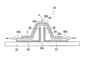
次に、第2の実施の形態に係る成形治具10について、図3を用いて説明する。本実施の形態に係る成形治具10は、第1の実施の形態に係る成形治具1のベース2及び下型3の構成を変更することにより、第1断熱部の位置を変更したものである。
【0039】
本実施の形態に係る成形治具10は、図3に示すように、所定位置に配置されるベース20と、ベース20の上に配置される下型30と、下型30の上に配置される上型40と、を備えている。上型40は、第1の実施の形態における上型4と実質的に同一である。
【0040】
ベース20は、図3に示すような平板状の部材であり、比較的高い熱伝導率を有する鉄合金又はアルミニウム合金で構成されている。ベース20の内部には、図示されていない熱源が内蔵されており、熱源から発する熱により下型3を介して樹脂を加熱することができる。本実施の形態におけるベース20には、第1の実施の形態におけるベース2と異なり、第1断熱部が設けられていない(図3参照)。
【0041】
下型30は、図3に示すように、両側の平坦部30aと、中央部分に設けられた突出部30bと、を有する断面凸形状の部材であり、アルミニウム合金で構成されている(図3参照)。
【0042】
下型30の下面部には、図3に示すように、1対の第1断熱部50が所定間隔をおいて設けられている。第1断熱部50は、ベース20の熱源から発する熱が下型30の上部に伝達されるのを部分的に遮断するものである。本実施の形態においては、下型30の突出部30b下方の下面部に所定間隔をおいて一端が配置され、平坦部30aの両端部まで延在するように埋設されたシリコン製の板状体を第1断熱部50として機能させている。
【0043】
また、下型30の突出部30b内には、第1断熱部50の内側の端面に当接し、突出部30b上部へと延在する1対の第2断熱部60が、所定間隔をおいて設けられている。第2断熱部60は、下型30に伝達された熱の伝導経路を形成するためのものである。本実施の形態においては、下型30の突出部30bに所定間隔をおいて埋設したシリコン製の板状体を第2断熱部60として機能させている。
【0044】
下型30の突出部30b内に設けられた第2断熱部60間の間隔は、第1断熱部50間の間隔とほぼ同一寸法とされており、図3の紙面左側に配置された第1断熱部50と第2断熱部60とが当接するとともに、図3の紙面右側に配置された第1断熱部50と第2断熱部60が当接している。
【0045】
以上の実施の形態に係る成形治具10においては、1対の第1断熱部50が下型30の下面部に所定間隔をおいて設けられ、下型30の平坦部30a下面から突出部30b上部へと延在する1対の第2断熱部60が下型30の突出部30b内に所定間隔をおいて設けられる。そして、第1断熱部50の一方と第2断熱部60の一方とが当接するとともに、第1断熱部50の他方と第2断熱部60の他方とが当接して、第1断熱部50間及び第2断熱部60間に熱伝導経路30cが形成されている。
【0046】
このため、ベース20の上に下型30を載置した際に、ベース20の熱源から発する熱は、この熱伝導経路30cを経由して下型30の突出部30b上部に伝達される。一方、下型30の下面部に第1断熱部50が設けられているので、ベース20の熱源から発する熱は、熱伝導経路30cが形成される部分を除いて、下型30の上方に直接的には伝達されない。
【0047】
従って、VARTM法による成形を行う場合に、樹脂導入口から最も遠い部位である下型30の突出部30b上部を最初に加熱し、樹脂導入口付近を最後に加熱することができる。この結果、加熱により樹脂の硬化収縮が発生した場合においても、樹脂導入管40bから樹脂を補充することができるので、成形品の内部や外部にボイドやクラックが形成されるのを防止することができ、高品質の製品を得ることができる。
【0048】
また、本実施の形態に係る成形治具10においては、ボイドやクラック等の形成を阻止するための下型の温度制御を、2種類の断熱部(第1断熱部50及び第2断熱部60)の組み合わせによって実現させている。従って、金型の温度制御のために従来要していた冷却管や断熱孔等の温度制御機構や制御装置が不要となり、治具の構成を格段に簡素化することができる。この結果、形状の異なる製品を少量ずつ成形する場合(多品種少量生産を行う場合)における費用及び手間を削減することができる。
【0049】
【発明の効果】
本発明によれば、ベース又は下型に設けられた第1断熱部と、下型に設けられた第2断熱部と、が当接して、ベースの熱源から発する熱を下型の突出部上方に伝達する熱伝導経路が形成される。従って、VARTM法による成形を行う場合に、樹脂導入口から最も遠い部位である下型の突出部上部を最初に加熱し、樹脂導入口付近を最後に加熱することができる。この結果、加熱により樹脂の硬化収縮が発生した場合においても、樹脂導入口から樹脂を補充することができるので、成形品の内部や外部にボイドやクラックが形成されるのを防止することができ、高品質の製品を得ることができる。
【0050】
また、本発明によれば、ボイドやクラック等の形成を阻止するための下型の温度制御を2種類の断熱部の組み合わせによって実現させているので、治具の構成を格段に簡素化することができる。この結果、多品種少量生産時における費用及び手間を削減することができる。
【図面の簡単な説明】
【図1】本発明の第1の実施の形態に係る成形治具の斜視図である。
【図2】図1のII−II部分の断面図である。
【図3】本発明の第2の実施の形態に係る成形治具の断面図である。
【符号の説明】
1、10 成形治具
2、20 ベース
3、30 下型
3b、30b 突出部
5、50 第1断熱部
6、60 第2断熱部[0001]
BACKGROUND OF THE INVENTION
The present invention relates to a molding jig, and more particularly, to a molding jig used when molding a fiber reinforced resin composite material having a cross-sectional hat shape by employing a VARTM (Vacuum Assist Resin Transfer Molding) method.
[0002]
[Prior art]
In recent years, fiber reinforced resin composites, which are lightweight and high-strength structural materials, have been used in various industrial fields such as the automobile and aerospace industries. As a method of molding such a fiber reinforced resin composite material, a reinforcing fiber is placed in a cavity formed in a predetermined mold, a molten resin is introduced into the cavity and impregnated into the reinforcing fiber, and the molten resin is heated. A curing method (hereinafter referred to as “RTM (Resin Transfer Molding) method”) has been proposed and put into practical use.
[0003]
In the RTM method described above, the molten resin introduced into the cavity in the mold is heated and cured. During this heating and curing, the volatile component of the resin is vaporized and the liquid state is changed to the solid state. As the resin shrinks due to curing, voids, cracks, etc. may be formed inside or outside the molded product.
[0004]
For the purpose of eliminating such problems, a resin reservoir is provided at the end of the mold to replenish the resin that has shrunk due to curing, but the vicinity of the resin reservoir is first heated to raise the temperature. As a result, the resin in the vicinity of the resin reservoir is hardened and it becomes impossible to replenish the resin. For this reason, a temperature control mechanism having a cooling pipe and a heat insulating hole is provided in the mold, and the temperature of the mold part is controlled by flowing a coolant through the cooling pipe to raise the temperature from a part far from the resin reservoir, A molding apparatus that effectively replenishes a resin has been proposed (see, for example, Patent Document 1).
[0005]
[Patent Document 1]
JP 7-156154 A (first page, FIG. 1)
[0006]
[Problems to be solved by the invention]
In the molding apparatus described in
[0007]
It is an object of the present invention to prevent the formation of voids and cracks due to curing shrinkage during molding, to realize high quality of molded products, and to reduce costs and labor at the time of high-mix low-volume production. It is to provide a forming jig that can be used.
[0008]
[Means for Solving the Problems]
In order to solve the above-described problems, the invention described in
[0009]
According to the first aspect of the present invention, the pair of first heat insulating portions provided at a predetermined interval on the upper surface portion of the base and the lower surface of the lower die provided at a predetermined interval in the protruding portion of the lower die. A pair of second heat insulating portions extending to the upper portion of the protruding portion. When the lower mold is placed on the base, one of the first heat insulating parts and one of the second heat insulating parts come into contact with each other, and the other of the first heat insulating parts and the other of the second heat insulating parts are in contact with each other. The base portion sandwiched between the pair of first heat insulation portions and the lower mold portion sandwiched between the pair of second heat insulation portions abut each other between the first heat insulation portions and the second. A heat conduction path is formed between the heat insulating portions. For this reason, the heat generated from the heat source of the base is transmitted to the upper part of the lower mold protrusion via this heat conduction path. On the other hand, due to the effect of the first heat insulating portion provided on the upper surface portion of the base, the heat generated from the heat source of the base is not directly transmitted to the lower mold except for the portion where the heat conduction path is formed.
[0010]
Therefore, when molding by the VARTM method (that is, a predetermined upper mold is disposed on the lower mold, an exhaust port is provided above the upper mold, and vacuuming is performed around the flat portion of the lower mold. When the resin is introduced between the lower mold and the upper mold from the provided resin inlet and the resin is heat-cured), the upper portion of the protruding portion of the lower mold can be heated first. Then, the heat transferred to the upper part of the lower mold is gradually transferred to the lower part of the lower mold via the side of the lower mold and finally the resin provided around the lower part of the lower mold. The vicinity of the inlet can be heated. That is, it is possible to first heat the upper part of the lower mold protrusion, which is the part farthest from the resin inlet, and finally heat the vicinity of the resin inlet.
[0011]
As a result, even when curing shrinkage of the resin occurs due to heating, the resin can be replenished from the resin inlet, so that voids and cracks can be prevented from being formed inside and outside the molded product. You can get a high quality product.
[0012]
According to the first aspect of the present invention, the temperature control of the lower mold for preventing the formation of voids, cracks and the like is realized by a combination of two types of heat insulating portions. Therefore, a temperature control mechanism and a control device such as a cooling pipe and a heat insulating hole, which are conventionally required for controlling the temperature of the mold, are unnecessary, and the configuration of the jig can be greatly simplified. As a result, it is possible to reduce costs and labor in the case where products having different shapes are molded in small amounts (when multi-product small-volume production is performed).
[0013]
The invention according to
[0014]
According to the second aspect of the present invention, a pair of first heat insulations are provided such that one end is disposed at a predetermined interval on the lower surface part below the projecting part of the lower mold and extends to the lower mold side end part. And a pair of second heat insulating portions provided at predetermined intervals in the lower mold protrusion and extending to the upper portion of the protrusion in contact with the pair of first heat insulating portions. When the lower mold is placed on the base, the lower mold portion sandwiched between the pair of second heat insulating portions abuts on the base, and heat is generated between the first heat insulating portions and between the second heat insulating portions. A conduction path is formed. For this reason, when a lower mold | type is mounted on a base, the heat | fever emitted from the heat source of a base can be transmitted to the upper part of the protrusion part of a lower mold | type via this heat conduction path | route. On the other hand, due to the effect of the first heat insulating portion, heat generated from the heat source of the base is not directly transmitted to the upper side of the lower mold.
[0015]
Therefore, when molding by the VARTM method, it is possible to first heat the upper part of the protrusion of the lower mold, which is the part farthest from the resin inlet, and finally heat the vicinity of the resin inlet. As a result, even when curing shrinkage of the resin occurs due to heating, the resin can be replenished from the resin inlet, so that voids and cracks can be prevented from being formed inside and outside the molded product. You can get a high quality product.
[0016]
According to the second aspect of the present invention, the temperature control of the lower mold for preventing the formation of voids, cracks and the like is realized by a combination of two types of heat insulating portions. Therefore, a temperature control mechanism and a control device such as a cooling pipe and a heat insulating hole, which are conventionally required for controlling the temperature of the mold, are unnecessary, and the configuration of the jig can be greatly simplified. As a result, it is possible to reduce costs and labor in the case where products having different shapes are molded in small amounts (when multi-product small-volume production is performed).
[0017]
DETAILED DESCRIPTION OF THE INVENTION
Hereinafter, embodiments of the present invention will be described in detail with reference to the drawings. The forming jig according to the present embodiment is used when a stringer (fiber reinforced resin composite material product) having a cross-sectional hat shape is formed using the VARTM method.
[0018]
[First embodiment]
Initially, the structure of the shaping |
[0019]
The
[0020]
As shown in FIG. 2, a pair of first
[0021]
When the
[0022]
As shown in FIGS. 1 and 2, the
[0023]
In the
[0024]
As shown in FIG. 2, the distance between the second
[0025]
As shown in FIGS. 1 and 2, the
[0026]
As shown in FIGS. 1 and 2, a plurality of
[0027]
Next, a procedure for forming a hat-shaped stringer by the VARTM method using the forming
[0028]
First, the
[0029]
Next, a stringer-forming preform (reinforced fiber fabric) is placed on the upper surface of the
[0030]
Next, the
[0031]
Next, a heating wire (heat source) built in the
[0032]
As a result, among the resins introduced into the cavity, the resin introduced near the upper portion B of the protruding
[0033]
In the forming
[0034]
For this reason, the heat generated from the heat source of the
[0035]
Therefore, when the vacuum is drawn from the
[0036]
As a result, even when the resin is cured and contracted by heating, the resin can be replenished from the
[0037]
Further, in the forming
[0038]
[Second Embodiment]
Next, a forming
[0039]
As shown in FIG. 3, the forming
[0040]
The
[0041]
As shown in FIG. 3, the
[0042]
As shown in FIG. 3, a pair of first
[0043]
Moreover, in the
[0044]
The interval between the second
[0045]
In the forming
[0046]
For this reason, when the lower mold |
[0047]
Therefore, when molding by the VARTM method, the upper portion of the
[0048]
Further, in the forming
[0049]
【The invention's effect】
According to the present invention, the first heat insulating part provided in the base or the lower mold and the second heat insulating part provided in the lower mold come into contact with each other to generate heat generated from the heat source of the base above the protruding part of the lower mold. A heat conduction path is formed for transmission to the. Therefore, when molding by the VARTM method, it is possible to first heat the upper part of the lower mold, which is the part farthest from the resin inlet, and finally heat the vicinity of the resin inlet. As a result, even when curing shrinkage of the resin occurs due to heating, the resin can be replenished from the resin inlet, so that voids and cracks can be prevented from being formed inside and outside the molded product. You can get a high quality product.
[0050]
Further, according to the present invention, the temperature control of the lower mold for preventing the formation of voids, cracks and the like is realized by a combination of two types of heat insulating parts, so that the configuration of the jig can be greatly simplified. Can do. As a result, it is possible to reduce the cost and labor at the time of multi-product small-volume production.
[Brief description of the drawings]
FIG. 1 is a perspective view of a forming jig according to a first embodiment of the present invention.
2 is a cross-sectional view taken along a line II-II in FIG.
FIG. 3 is a cross-sectional view of a forming jig according to a second embodiment of the present invention.
[Explanation of symbols]
1, 10
Claims (2)
熱伝導材料から構成され中央部分に突出部を有する凸状断面の下型と、
前記ベースの上面部に所定間隔をおいて設けられる1対の第1断熱部と、
前記下型の前記突出部内に所定間隔をおいて設けられ、前記下型の下面から前記突出部上部まで延在する1対の第2断熱部と、
を備え、
前記ベースの上に前記下型を載置した際に、前記第1断熱部の一方と前記第2断熱部の一方とが当接するとともに、前記第1断熱部の他方と前記第2断熱部の他方とが当接し、かつ、前記1対の第1断熱部に挟まれた前記ベースの部分と、前記1対の第2断熱部に挟まれた前記下型の部分と、が当接することを特徴とする成形治具。A base with a built-in heat source,
A lower mold of a convex cross section made of a heat conductive material and having a protrusion in the central portion;
A pair of first heat insulating portions provided at predetermined intervals on the upper surface portion of the base;
A pair of second heat insulating portions provided at predetermined intervals in the protrusion of the lower mold and extending from the lower surface of the lower mold to the upper portion of the protrusion;
With
When the lower mold is placed on the base, one of the first heat insulating parts and one of the second heat insulating parts come into contact with each other, and the other of the first heat insulating parts and the second heat insulating part The base part sandwiched between the pair of first heat insulation parts and the lower mold part sandwiched between the pair of second heat insulation parts are in contact with each other. Characteristic forming jig.
熱伝導材料から構成され中央部分に突出部を有する凸状断面の下型と、
前記下型の前記突出部下方の下面部に所定間隔をおいて一端が配置され、前記下型側端部まで延在するように設けられる1対の第1断熱部と、
前記下型の前記突出部内に所定間隔をおいて設けられ、前記1対の第1断熱部に各々当接して前記突出部上部まで延在する1対の第2断熱部と、
を備え、
前記ベースの上に前記下型を載置した際に、前記1対の第2断熱部に挟まれた前記下型の部分が、前記ベースに当接することを特徴とする成形治具。A base with a built-in heat source,
A lower mold of a convex cross section made of a heat conductive material and having a protrusion in the central portion;
A pair of first heat insulating portions provided with one end disposed at a predetermined interval on the lower surface portion of the lower mold below the protruding portion and extending to the lower mold side end;
A pair of second heat insulating portions provided at predetermined intervals in the projecting portion of the lower mold and extending to the upper portions of the projecting portions in contact with the pair of first heat insulating portions;
With
When the lower mold is placed on the base, a portion of the lower mold sandwiched between the pair of second heat insulating portions comes into contact with the base.
Priority Applications (1)
| Application Number | Priority Date | Filing Date | Title |
|---|---|---|---|
| JP2003122613A JP4084697B2 (en) | 2003-04-25 | 2003-04-25 | Molding jig |
Applications Claiming Priority (1)
| Application Number | Priority Date | Filing Date | Title |
|---|---|---|---|
| JP2003122613A JP4084697B2 (en) | 2003-04-25 | 2003-04-25 | Molding jig |
Publications (2)
| Publication Number | Publication Date |
|---|---|
| JP2004322542A JP2004322542A (en) | 2004-11-18 |
| JP4084697B2 true JP4084697B2 (en) | 2008-04-30 |
Family
ID=33500781
Family Applications (1)
| Application Number | Title | Priority Date | Filing Date |
|---|---|---|---|
| JP2003122613A Expired - Fee Related JP4084697B2 (en) | 2003-04-25 | 2003-04-25 | Molding jig |
Country Status (1)
| Country | Link |
|---|---|
| JP (1) | JP4084697B2 (en) |
Families Citing this family (3)
| Publication number | Priority date | Publication date | Assignee | Title |
|---|---|---|---|---|
| JP4833603B2 (en) * | 2005-07-15 | 2011-12-07 | 富士重工業株式会社 | Molding jig |
| JP4967405B2 (en) * | 2006-03-27 | 2012-07-04 | 東レ株式会社 | Manufacturing method of fiber reinforced plastic |
| CN109468786B (en) * | 2018-11-30 | 2023-09-05 | 苏州爱慕内衣有限公司 | Regional temperature control die |
-
2003
- 2003-04-25 JP JP2003122613A patent/JP4084697B2/en not_active Expired - Fee Related
Also Published As
| Publication number | Publication date |
|---|---|
| JP2004322542A (en) | 2004-11-18 |
Similar Documents
| Publication | Publication Date | Title |
|---|---|---|
| CN110077015B (en) | Fillet filler and method for manufacturing fillet filler and composite structure | |
| US5709893A (en) | Breathable tooling for forming parts from volatile-emitting composite materials | |
| KR101582705B1 (en) | Rtm method and method for manufacturing fiber-reinforced resin molded body | |
| US20170015066A1 (en) | Additive manufacturing system and method for performing additive manufacturing on thermoplastic sheets | |
| JP6990664B2 (en) | Methods and equipment for casting and solidifying fiber preforms | |
| WO2011081016A1 (en) | Casting method and casting device for cast-metal object | |
| EP3406412B1 (en) | Fiber-reinforced composite member molding apparatus | |
| CN102216057A (en) | Method for producing a concave-shaped in particular u-shaped piece in a composite material and device for carrying out the same | |
| JP6439879B2 (en) | Composite material manufacturing method and composite material manufacturing apparatus | |
| JP5733306B2 (en) | Preform manufacturing apparatus and manufacturing method | |
| JP4084697B2 (en) | Molding jig | |
| EP3702155B1 (en) | Method for preparing a composite product and composite product | |
| KR20140108634A (en) | Thermoplastic resin molded article having hollow portion and method for manufacturing same | |
| KR100850332B1 (en) | Mold assembly comprising an anisotropic heat diffuser plate | |
| JP5791365B2 (en) | RTM molding method and RTM molding apparatus | |
| JP2005246902A (en) | Resin transfer molding (rtm) method | |
| JP2008132717A (en) | Manufacturing method of fiber-reinforced plastic | |
| JP6432750B2 (en) | Fiber reinforced composite material molding equipment | |
| JP2010221489A (en) | Rtm molding method | |
| JP2009196236A (en) | Production method of thermoplastic resin molding and thermoplastic resin molding | |
| JP2009160879A (en) | Method for manufacturing fiber reinforced resin structure | |
| JP6052526B1 (en) | Fiber reinforced composite material molding equipment | |
| JP2020526414A (en) | Methods and equipment for manufacturing parts by injecting resin into woven fiber preforms | |
| JP6971690B2 (en) | Manufacturing method for flexible mandrel and composite parts | |
| JPH0535235U (en) | Fiber-reinforced resin molding core material |
Legal Events
| Date | Code | Title | Description |
|---|---|---|---|
| A621 | Written request for application examination |
Free format text: JAPANESE INTERMEDIATE CODE: A621 Effective date: 20060331 |
|
| A977 | Report on retrieval |
Free format text: JAPANESE INTERMEDIATE CODE: A971007 Effective date: 20080131 |
|
| TRDD | Decision of grant or rejection written | ||
| A01 | Written decision to grant a patent or to grant a registration (utility model) |
Free format text: JAPANESE INTERMEDIATE CODE: A01 Effective date: 20080212 |
|
| A61 | First payment of annual fees (during grant procedure) |
Free format text: JAPANESE INTERMEDIATE CODE: A61 Effective date: 20080215 |
|
| R150 | Certificate of patent or registration of utility model |
Ref document number: 4084697 Country of ref document: JP Free format text: JAPANESE INTERMEDIATE CODE: R150 Free format text: JAPANESE INTERMEDIATE CODE: R150 |
|
| FPAY | Renewal fee payment (event date is renewal date of database) |
Free format text: PAYMENT UNTIL: 20110222 Year of fee payment: 3 |
|
| FPAY | Renewal fee payment (event date is renewal date of database) |
Free format text: PAYMENT UNTIL: 20120222 Year of fee payment: 4 |
|
| R250 | Receipt of annual fees |
Free format text: JAPANESE INTERMEDIATE CODE: R250 |
|
| FPAY | Renewal fee payment (event date is renewal date of database) |
Free format text: PAYMENT UNTIL: 20120222 Year of fee payment: 4 |
|
| FPAY | Renewal fee payment (event date is renewal date of database) |
Free format text: PAYMENT UNTIL: 20130222 Year of fee payment: 5 |
|
| R250 | Receipt of annual fees |
Free format text: JAPANESE INTERMEDIATE CODE: R250 |
|
| FPAY | Renewal fee payment (event date is renewal date of database) |
Free format text: PAYMENT UNTIL: 20140222 Year of fee payment: 6 |
|
| R250 | Receipt of annual fees |
Free format text: JAPANESE INTERMEDIATE CODE: R250 |
|
| R250 | Receipt of annual fees |
Free format text: JAPANESE INTERMEDIATE CODE: R250 |
|
| S531 | Written request for registration of change of domicile |
Free format text: JAPANESE INTERMEDIATE CODE: R313531 |
|
| R350 | Written notification of registration of transfer |
Free format text: JAPANESE INTERMEDIATE CODE: R350 |
|
| R250 | Receipt of annual fees |
Free format text: JAPANESE INTERMEDIATE CODE: R250 |
|
| R250 | Receipt of annual fees |
Free format text: JAPANESE INTERMEDIATE CODE: R250 |
|
| R250 | Receipt of annual fees |
Free format text: JAPANESE INTERMEDIATE CODE: R250 |
|
| S533 | Written request for registration of change of name |
Free format text: JAPANESE INTERMEDIATE CODE: R313533 |
|
| R350 | Written notification of registration of transfer |
Free format text: JAPANESE INTERMEDIATE CODE: R350 |
|
| R250 | Receipt of annual fees |
Free format text: JAPANESE INTERMEDIATE CODE: R250 |
|
| R250 | Receipt of annual fees |
Free format text: JAPANESE INTERMEDIATE CODE: R250 |
|
| LAPS | Cancellation because of no payment of annual fees |