JP4084598B2 - sewing machine - Google Patents
sewing machine Download PDFInfo
- Publication number
- JP4084598B2 JP4084598B2 JP2002135501A JP2002135501A JP4084598B2 JP 4084598 B2 JP4084598 B2 JP 4084598B2 JP 2002135501 A JP2002135501 A JP 2002135501A JP 2002135501 A JP2002135501 A JP 2002135501A JP 4084598 B2 JP4084598 B2 JP 4084598B2
- Authority
- JP
- Japan
- Prior art keywords
- hook
- hook cover
- cover
- sewing machine
- bed portion
- Prior art date
- Legal status (The legal status is an assumption and is not a legal conclusion. Google has not performed a legal analysis and makes no representation as to the accuracy of the status listed.)
- Expired - Fee Related
Links
Images


Landscapes
- Sewing Machines And Sewing (AREA)
Description
【0001】
【発明の属する技術分野】
本発明はミシンに係り、特に、シリンダベッド部の下方を覆う釜カバーをベッド部に対して開閉可能としたミシンに関する。
【0002】
【従来の技術】
筒状の被縫製物を縫製するシリンダベッド型ミシンにおいては、被縫製物をシリンダベッド部の周囲を覆うようにした状態で縫製が行なわれる。シリンダベッド部には釜部が配置されているが、この釜部は高速で摺動運動するため、潤滑を必要とする。その潤滑は例えば、オイルパンからポンプを介して釜軸内の給油経路へ潤滑油を供給し、その給油経路から釜部の摺動部へ油を供給することにより行なわれる。釜部へ供給された油は釜の回転に伴い回りに飛散し、落下する。上記のように、縫製の際には被縫製物がシリンダベッド部の周囲を覆うので、この被縫製物に油が付着しないように釜カバーが必要となる。
【0003】
このような釜カバーを備えたミシンの従来例を図8及び9を参照して説明する。このミシンのベッド部201は、本体ベッド部202と、該本体ベッド部202に比して細長い形状のシリンダベッド部203からなる。本体ベッド部202の下方には潤滑油204を貯留するオイルパン205が配置されている。シリンダベッド部203部の下方には、該シリンダベッド部203の下方を覆う釜カバー206が配されている。シリンダベッド部203内の図示しない釜部から釜カバー206へ落下した潤滑油をオイルパン205へ還流するため、釜カバー206のベッド部201側端部はオイルパン205の隔壁205aよりも本体ベッド部202側(図の右側)に位置するように配置されている。
【0004】
シリンダベッド部203内の釜部には図示しない下糸ボビンケースが収納されていて、下糸を補給する際にはオペレータがこの下糸ボビンケースを取り外し、新たな下ボビンケースと交換する。従って、釜カバー206はベッド部201に対して開閉可能に取り付けられている。
【0005】
【発明が解決しようとする課題】
釜カバー206を開閉可能とするため従来はヒンジや回転軸等の、それ自体が回転中心となるような回転支点部材207を用いている。回転支点部材207は、ヒンジの場合はベッド部201へ取り付ける部材と釜カバー206へ取り付ける部材を有する。また、回転軸を用いる場合は該回転軸をベッド部201へ固定すると共に、該回転軸により釜カバー206を回転可能に支持しなければならない。このため、回転支点部材207の回転中心は図8のように本体ベッド部202と釜カバー206の境界部分或いは図9のようにシリンダベッド部203且つ釜カバー206の重合部分となる。いずれの場合もその回転中心はオイルパン205の隔壁205aより本体ベッド部202側に位置する。また、該隔壁205aの上端よりも上方に位置するのが通常である。
【0006】
このような開閉機構の場合、図から明らかなように、釜カバー206を開放するため図の反時計方向に回動する際、オイルパン205の隔壁205aと最初に干渉する釜カバー206の部位は釜カバー206の、本体ベッド部202側の下方端210近傍である。釜カバー206を開放時、図の仮想線で示した位置206aまで開放する必要があるとすると、釜カバー206がオイルパン205の隔壁205aと干渉しないためには隔壁205aの上端は図の仮想線の下方に位置しなければならない。このため、釜カバー206とオイルパン205の隔壁205a上端との間の隙間208が大きくなる。また、オイルパン205の隔壁205aが低くなる。
【0007】
オイルパン205内の潤滑油204はミシン運転中には霧状の油が充満している。従って、上記隙間208が大きいと、該隙間208から油がミシン外へ漏出しやすい。また、オイルパン205の隔壁205aが低いと潤滑油204の液面と隔壁205a上端とが接近するため、油がミシン外へ漏出しやすくなる。
【0008】
また、ヒンジのような回転支点部材は壊れ易く、しかも高価である。
また、図9のように、釜カバー206内に回転中心がある場合には、釜カバー206の開放時、反時計方向に回動する際に、釜カバー206の一部分が上方へ移動し、且つその移動量が無視できない大きさなので、シリンダベッド部203内の機構部品、或いはシリンダベッド部203自体と干渉しやすくなる。
【0009】
また、上記のような形状の釜カバー206の場合、その下方端部210付近に残っている油が釜カバー206の開放時に釜カバー206の縁部を伝って裏面212に移動することがある。釜カバー206の裏面212に油が付着すると、縫製時に被縫製物を汚すことになる。
【0010】
本発明の目的は、釜カバーの回転軌跡及び回転中心を選択する際の自由度が高い構成を有するミシンを提供することにある。
【0011】
本発明の他の目的は、ヒンジのように壊れ易くしかも高価な回転支点部材を用いずに釜カバーを開閉可能なミシンを提供することにある。
【0012】
本発明の更に他の目的は、オイルパンの壁との間の隙間を狭くし、該隙間から油がミシン外へ漏出するのを防止することができるミシンを提供することにある。
【0013】
【発明を解決するための手段】
上記目的を達成するために請求項1記載の発明は、
本体ベッド部とシリンダベッド部からなるベッド部と、
前記ベッド部の下方に配置され、隔壁が形成されたオイルパンと、
前記シリンダベッド部下方に配置された釜と、
前記釜の摺動部に潤滑油を送る給油経路と、
前記シリンダベッド部の下方を覆い、前記潤滑油をオイルパンに還流可能な釜カバーとを備え、該釜カバーを前記ベッド部に対して開閉可能としたミシンにおいて、
前記ベッド部と釜カバーの一方にほぼ円弧状のガイド溝、他方に該ガイド溝に嵌合するガイドピンを設け、
前記釜カバーが回動した時に少なくとも前記釜内のボビンケースの処理が可能なように前記釜カバーの移動を規制するストッパとを備え、
前記釜カバーが回動した時に前記円弧状のガイド溝の円弧中心が前記釜カバー
下方に位置するように、前記前記ガイド溝を形成すると共に、
前記釜カバーの前記オイルパン側の端部が、前記オイルパン隔壁を越えてオイルパン側に配置され、且つ下方に向けてほぼ円弧状の湾曲部を有し、
前記湾曲部の円弧中心が前記ガイド溝の円弧中心とほぼ一致する構成とした。
請求項2記載の発明は、請求項1記載のミシンにおいて、
前記ストッパは、
前記ベッド部に固定されたストッパピンと、
一端側が前記ベッド部に支持されるバネと、
前記バネの他端側を支持するとともに、前記釜カバーに連結されるストッパ部材を備え、
前記釜カバーが回動した時に前記ストッパ部材が前記ストッパピンに当接して前記釜カバーの移動を規制する構成とした。
【0017】
【発明の実施の形態】
以下本発明のミシンを図面に示した実施形態に基づいて説明する。
【0018】
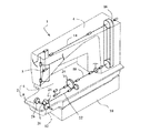
先ず、図4および5に基づいて本発明のミシンの概略構成を説明する。このミシン1は、針棒3を図示しない針振り機構により、被縫製物の搬送方向と直交する方向へ移動可能な千鳥ミシンであり、ベッド部2と、ベッド部2から立設されたアーム部4を備える。ベッド部2は本体ベッド部6と、本体ベッド部6に比して細長状のシリンダベッド部8から構成される。本体ベッド部6の下方には潤滑油を貯留するオイルパン10が配され、シリンダベッド部8の下方には釜カバー12が配されている。この釜カバー12は、ベッド部2に対して開閉可能とされている。
【0019】
図示しない駆動源によって回転駆動される上軸14の回転はタイミングベルト16を介して下軸18に伝達される。下軸18の回転は、ギヤ装置20を介して回転数を変化した上で釜駆動軸22へ伝達される。釜駆動軸22の回転は、ギヤ装置24を介して釜軸26へ伝達される。下軸18と釜駆動軸22とは平行に配置されているが、釜駆動軸22と釜軸26とは直交する方向に配置されている。従って、ギヤ装置20は平歯車で構成され、ギヤ装置24は傘歯車で構成されている。釜軸26の先端には釜28が取り付けられている。
【0020】
上記の各機構部品のうちギヤ装置24、釜軸26、釜28がシリンダベッド部8内に配置され、下軸18、ギヤ装置20、釜駆動軸22等が本体ベッド部6内に配置されている。なお図示しない動メス等もシリンダベッド部8内に配置されている。シリンダベッド部8は、上記ギヤ装置24、釜軸26、釜28及び動メス等の機構部品を収納するためのスペース以外の部分は切り欠いて筒状の被縫製物を縫製可能としている。
【0021】
図6および7に示すように、釜28の内部に給油経路32が形成されていて、この給油経路32へ図示しない給油チューブが接続されている。給油チューブにはオイルパン10から図示しないポンプを介して潤滑油が送られている。給油チューブから給油経路32に供給された油は、釜軸メタル30と釜軸26の摺動面および釜28摺動部の潤滑を行う。釜28にはボビン36を収納したボビンケース38が収納されている。ギヤ装置20,24はそれぞれギヤボックス40,42内に収納されていて、各ギヤ装置20,24の下部にはアンダーカバー44,46がベッド部2下部にネジ止め固定されている。
【0022】
釜28近傍に配置される図示しない動メスにより針糸が捕捉され切断される。この動メスはメス二又48に支持されている。本体ベッド部6には図示しない糸切り駆動部が配され、動メスを駆動するためのリンク体50が、その一端50aを糸切り駆動部に連結され、他端50bをメス二又48に連結されている。
【0023】
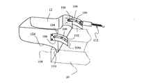
次に図1および2を参照して、本実施形態の特徴部分である釜カバー12の開閉機構を説明する。この開閉機構は釜カバー12に固定されたガイド部材102に形成されたガイド溝104と、ベッド部2に固定されたガイドピン106を備える。ガイドピン106はガイド溝104と嵌合する形状とされている。図示した例ではガイド溝104を釜カバー12側に設け、ガイドピン106をベッド部2側に設けているが、これとは逆にガイド溝104をベッド部2側に、ガイドピン106を釜カバー12側に設けてもよい。
【0024】
ガイド溝104はほぼ円弧状の曲率円として形成され、その曲率中心12Cは釜カバー12から下方に離隔し、且つオイルパン10の隔壁108近傍に位置する。図示した例では円弧中心12Cは隔壁108より若干左側に位置しているが、可能であれば隔壁108と一致させることが望ましい。釜カバー12がガイド溝104に沿って開閉運動をする際にはこの曲率中心12Cを中心として移動することとなる。図の円D1は曲率中心12Cから釜カバー12のガイド溝104部迄の距離を半径として描いた円であり、釜カバー12のガイド溝104部の運動軌跡はこの円D1の一部となる。
【0025】
釜カバー12は、オイルパン10側の下方端部110がオイルパン10の隔壁108よりもオイルパン10側に位置するように配されている。ミシン運転中に釜部から落下した油は釜カバー12の底部から下方端部110を通ってオイルパン10内に還流される。この下方端部110にはほぼ円弧状の曲率形状の湾曲部が形成されていてその曲率中心はガイド溝104の曲率中心12Cとほぼ一致するようにされている。従って、この下方端部110は下方に向けて傾斜していて、該下方端部110近傍の潤滑油がオイルパン10内へ還流するようになっている。図の円D2は曲率中心12Cから釜カバー12の下方端部110迄の距離を半径として描いた円であり、釜カバー12の下方端部110の運動軌跡はこの円D2の一部となる。
【0026】
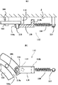
112は釜カバー12の開放時の移動を規制するストッパであり、図3に詳細に示したように、ベッド部2に固定されたストッパピン114およびバネ止めピン115、ガイド部材102に固定された係合ピン116、係合ピン116に係合可能且つストッパピン114と当接可能なストッパ部材118、ストッパ部材118とバネ止めピン115の間に設けられたバネ120とから構成される。ストッパ部材118は、その一端側にフック部118aが形成されていて、係合ピン116にそのフック部118aを掛けることにより釜カバー12と連結される。ストッパ部材118の他端側は、バネ120を介してベッド部2に連結されると共にベッド部2方向に突出する突起部118bが形成されている。
【0027】
ボビン36(図6、7)の糸が消費されてボビンケース38を交換する場合等に釜カバー12を回動する。釜カバー12を回動するとストッパ部材118は係合ピン116を介してストッパピン114側に移動し、突起部118bがストッパピン114と当接した時点で釜カバー12の開放時の回動運動を規制(停止)する。従って、ストッパ112は、少なくともボビンケース交換処理が可能な角度だけ釜カバー12が回動した時に該釜カバー12の移動を規制(停止)するように構成されている。
【0028】
従って釜カバー12は、曲率中心12Cを中心としてストッパ112によって規制されるまで回動して図2に仮想線で示す位置12aに至る。この回動の間、釜カバー12の下方端部110は図2の円D2の円周に沿って移動するので、オイルパン10の隔壁108との間の距離がほぼ一定であり、干渉することがない。従って、釜カバー12のオイルパン10側の下方端部110とオイルパン10の隔壁108との間の間隙122を小さくすることが可能となり、オイルパン10からミシン外への油の漏出を効果的に防止することができる。
【0029】
また、釜カバー12の下方端部110は、下方に向けて傾斜しているが、この下方への傾斜は、釜カバー12の開閉時常に維持されている。従って、下方端部110付近に残っている油が釜カバー12の開放時に釜カバー12の裏面12dに伝って移動することなく、オイルパン10へ還流される。
【0030】
本実施形態においては、釜カバー12側に設けられたガイド溝104の先端側が開放端104aとなっているので、ベッド部2から釜カバー12を簡単に取り外し可能となっている。取り外す際には、ガイド部材102の係合ピン116からストッパ部材118のフック部118aを取り外すことによってストッパ112の規制を解除した後、ガイド溝104から2つのガイドピン106が外れるまで釜カバー12を曲率中心12Cの回りに回動すればよい。
【0031】
本発明においては、ほぼ円弧状のガイド溝104とこのガイド溝104と嵌合するガイドピン106を設け、ガイド溝104の形状に沿って開閉可能としたので、その運動軌跡の中心を任意に選択可能となった。この点が従来のようにヒンジ等の、それ自体が回転中心となるような支点部材とは根本的に異なる特徴である。従って、本発明の開閉機構の場合においては、回転軌跡及び回転中心の選定の自由度が高く、設計上の種々の制約の下で最も適当とされる点を回転中心と定めることができる。
【0032】
以上、本発明を図面に示した実施形態に基づいて説明したが、本発明はこの実施形態には限定されず種々変更可能である。例えば、本実施形態は本発明を千鳥ミシンに適用した例を示したが、シリンダベッド部の下方を覆う釜カバーをベッド部に対して開閉可能としたミシンであればどのようなミシンにも適用可能である。
【0033】
【発明の効果】
請求項1、2記載の発明によれば、釜カバーとオイルパンとの隙間を狭くすることができ、該隙間から油がミシン外へ漏出するのを防止することができる。更に、釜カバー下方端部付近に残っている油が釜カバーの開放時に釜カバーの裏面に伝わって移動することなく効果的にオイルパンへ還流される。
【図面の簡単な説明】
【図1】 本発明に係るミシンの実施形態の要部の斜視図である。
【図2】 本実施形態のミシンの要部の断面図である。
【図3】 本実施形態のミシンのストッパを示す図である。
【図4】 本実施形態のミシンの外観斜視図である。
【図5】 本実施形態のミシンの基本的な機構を示す斜視図である。
【図6】 本実施形態のミシンの要部の下面図である。
【図7】 本実施形態のミシンの要部の側面図である。
【図8】 従来例のミシンの要部の断面図である。
【図9】 他の従来例のミシンの要部の断面図である。
【符号の説明】
2 ベッド部
6 本体ベッド部
8 シリンダベッド部
10 オイルパン
12 釜カバー
12C 円弧中心
28 釜
38 ボビンケース
104 ガイド溝
106 ガイドピン
110 下方端
112 ストッパ[0001]
BACKGROUND OF THE INVENTION
The present invention relates to a sewing machine, and more particularly to a sewing machine that can open and close a shuttle cover that covers a lower portion of a cylinder bed portion with respect to a bed portion.
[0002]
[Prior art]
In a cylinder bed type sewing machine that sews a cylindrical workpiece, sewing is performed in a state where the periphery of the cylinder bed portion is covered with the workpiece. The cylinder bed portion is provided with a hook portion, but this hook portion slides at a high speed and therefore requires lubrication. The lubrication is performed, for example, by supplying the lubricating oil from the oil pan to the oil supply path in the hook shaft through the pump and supplying the oil from the oil supply path to the sliding part of the hook part. The oil supplied to the hook part is scattered around and falls as the hook rotates. As described above, when sewing is performed, the sewing product covers the periphery of the cylinder bed portion, and thus a hook cover is necessary so that oil does not adhere to the sewing product.
[0003]
A conventional example of a sewing machine having such a shuttle cover will be described with reference to FIGS. The
[0004]
A lower thread bobbin case (not shown) is accommodated in the hook portion in the
[0005]
[Problems to be solved by the invention]
In order to make the
[0006]
In the case of such an opening / closing mechanism, as is apparent from the figure, when the
[0007]
The lubricating
[0008]
Further, a rotation fulcrum member such as a hinge is fragile and expensive.
In addition, as shown in FIG. 9, when the
[0009]
Further, in the case of the
[0010]
An object of the present invention is to provide a sewing machine having a configuration with a high degree of freedom in selecting a rotation locus and a rotation center of a shuttle cover.
[0011]
Another object of the present invention is to provide a sewing machine that can open and close the shuttle cover without using a rotary fulcrum member that is fragile and expensive like a hinge.
[0012]
Still another object of the present invention is to provide a sewing machine that can narrow a gap with an oil pan wall and prevent oil from leaking out of the sewing machine through the gap.
[0013]
[Means for Solving the Invention]
In order to achieve the above object, the invention described in
A bed portion comprising a main body bed portion and a cylinder bed portion;
An oil pan disposed below the bed portion and having a partition wall ;
A hook disposed below the cylinder bed,
An oil supply path for sending lubricating oil to the sliding portion of the hook;
A sewing machine that covers a lower portion of the cylinder bed portion and includes a hook cover capable of returning the lubricating oil to an oil pan, wherein the hook cover can be opened and closed with respect to the bed portion.
A substantially arc-shaped guide groove is provided on one of the bed portion and the hook cover, and a guide pin that fits in the guide groove is provided on the other.
A stopper for restricting the movement of the hook cover so that at least the bobbin case in the hook can be processed when the hook cover rotates,
Forming the guide groove so that the arc center of the arc-shaped guide groove is located below the hook cover when the hook cover is rotated;
The oil pan side end portion of the hook cover is disposed on the oil pan side beyond the oil pan partition wall, and has a substantially arc-shaped curved portion downward.
The arc center of the curved portion is configured to substantially coincide with the arc center of the guide groove.
The invention according to
The stopper is
A stopper pin fixed to the bed part;
A spring whose one end is supported by the bed portion;
A stopper member that supports the other end of the spring and is connected to the shuttle cover;
When the hook cover is rotated, the stopper member abuts against the stopper pin to restrict the movement of the hook cover.
[0017]
DETAILED DESCRIPTION OF THE INVENTION
The sewing machine of the present invention will be described below based on the embodiments shown in the drawings.
[0018]
First, the schematic configuration of the sewing machine of the present invention will be described with reference to FIGS. This
[0019]
The rotation of the
[0020]
Of the above-described mechanical components, the
[0021]
As shown in FIGS. 6 and 7, an
[0022]
The needle thread is captured and cut by a moving knife (not shown) disposed in the vicinity of the
[0023]
Next, with reference to FIGS. 1 and 2, the opening / closing mechanism of the
[0024]
The
[0025]
The
[0026]
[0027]
When the bobbin 36 (FIGS. 6 and 7) is consumed and the
[0028]
Accordingly, the
[0029]
The
[0030]
In the present embodiment, the front end side of the
[0031]
In the present invention, a substantially arc-shaped
[0032]
As mentioned above, although this invention was demonstrated based on embodiment shown on drawing, this invention is not limited to this embodiment, and can be variously changed. For example, the present embodiment shows an example in which the present invention is applied to a staggered sewing machine, but the sewing machine can be applied to any sewing machine as long as the hook cover that covers the lower part of the cylinder bed part can be opened and closed with respect to the bed part. Is possible.
[0033]
【The invention's effect】
According to invention of
[Brief description of the drawings]
FIG. 1 is a perspective view of a main part of an embodiment of a sewing machine according to the present invention.
FIG. 2 is a cross-sectional view of a main part of the sewing machine according to the present embodiment.
FIG. 3 is a view showing a sewing machine stopper according to the present embodiment;
FIG. 4 is an external perspective view of the sewing machine according to the present embodiment.
FIG. 5 is a perspective view showing a basic mechanism of the sewing machine according to the present embodiment.
FIG. 6 is a bottom view of a main part of the sewing machine according to the present embodiment.
FIG. 7 is a side view of a main part of the sewing machine according to the present embodiment.
FIG. 8 is a cross-sectional view of a main part of a conventional sewing machine.
FIG. 9 is a cross-sectional view of a main part of another conventional sewing machine.
[Explanation of symbols]
2 Bed portion 6 Body bed portion 8
Claims (2)
前記ベッド部の下方に配置され、隔壁が形成されたオイルパンと、
前記シリンダベッド部下方に配置された釜と、
前記釜の摺動部に潤滑油を送る給油経路と、
前記シリンダベッド部の下方を覆い、前記潤滑油をオイルパンに還流可能な釜カバーとを備え、該釜カバーを前記ベッド部に対して開閉可能としたミシンにおいて、
前記ベッド部と釜カバーの一方にほぼ円弧状のガイド溝、他方に該ガイド溝に嵌合するガイドピンを設け、
前記釜カバーが回動した時に少なくとも前記釜内のボビンケースの処理が可能なように前記釜カバーの移動を規制するストッパとを備え、
前記釜カバーが回動した時に前記円弧状のガイド溝の円弧中心が前記釜カバー下方に位置するように、前記前記ガイド溝を形成すると共に、
前記釜カバーの前記オイルパン側の端部が、前記オイルパン隔壁を越えてオイルパン側に配置され、且つ下方に向けてほぼ円弧状の湾曲部を有し、
前記湾曲部の円弧中心が前記ガイド溝の円弧中心とほぼ一致することを特徴とするミシン。A bed portion comprising a main body bed portion and a cylinder bed portion;
An oil pan disposed below the bed portion and having a partition wall ;
A hook disposed below the cylinder bed,
An oil supply path for sending lubricating oil to the sliding portion of the hook;
A sewing machine that covers a lower portion of the cylinder bed portion and includes a hook cover capable of returning the lubricating oil to an oil pan.
A substantially arc-shaped guide groove is provided on one of the bed portion and the hook cover, and a guide pin that fits in the guide groove is provided on the other.
A stopper that restricts the movement of the hook cover so that at least the bobbin case in the hook can be processed when the hook cover rotates,
Forming the guide groove so that the arc center of the arc-shaped guide groove is located below the hook cover when the hook cover is rotated;
The oil pan side end of the hook cover is disposed on the oil pan side beyond the oil pan partition, and has a substantially arc-shaped curved portion downward.
The sewing machine characterized in that an arc center of the curved portion substantially coincides with an arc center of the guide groove.
前記ストッパは、
前記ベッド部に固定されたストッパピンと、
一端側が前記ベッド部に支持されるバネと、
前記バネの他端側を支持するとともに、前記釜カバーに連結されるストッパ部材を備え、
前記釜カバーが回動した時に前記ストッパ部材が前記ストッパピンに当接して前記釜カバーの移動を規制することを特徴とするミシン。The sewing machine according to claim 1, wherein
The stopper is
A stopper pin fixed to the bed part;
A spring whose one end is supported by the bed portion;
A stopper member that supports the other end of the spring and is connected to the shuttle cover,
The sewing machine according to claim 1, wherein when the hook cover is rotated, the stopper member abuts against the stopper pin to restrict the movement of the hook cover.
Priority Applications (2)
| Application Number | Priority Date | Filing Date | Title |
|---|---|---|---|
| JP2002135501A JP4084598B2 (en) | 2002-05-10 | 2002-05-10 | sewing machine |
| CNB031306942A CN100398718C (en) | 2002-05-10 | 2003-05-07 | Rotary shutter cover |
Applications Claiming Priority (1)
| Application Number | Priority Date | Filing Date | Title |
|---|---|---|---|
| JP2002135501A JP4084598B2 (en) | 2002-05-10 | 2002-05-10 | sewing machine |
Publications (3)
| Publication Number | Publication Date |
|---|---|
| JP2003326072A JP2003326072A (en) | 2003-11-18 |
| JP2003326072A5 JP2003326072A5 (en) | 2005-09-29 |
| JP4084598B2 true JP4084598B2 (en) | 2008-04-30 |
Family
ID=29416749
Family Applications (1)
| Application Number | Title | Priority Date | Filing Date |
|---|---|---|---|
| JP2002135501A Expired - Fee Related JP4084598B2 (en) | 2002-05-10 | 2002-05-10 | sewing machine |
Country Status (2)
| Country | Link |
|---|---|
| JP (1) | JP4084598B2 (en) |
| CN (1) | CN100398718C (en) |
Family Cites Families (3)
| Publication number | Priority date | Publication date | Assignee | Title |
|---|---|---|---|---|
| IT1161140B (en) * | 1983-04-20 | 1987-03-11 | Rockwell Rimoldi Spa | WORK TRANSPORT DEVICE IN SEWING MACHINES |
| CN2180661Y (en) * | 1993-08-30 | 1994-10-26 | 卢涛 | Shuttle carrier and shuttle mechanism for sewing machine |
| JPH11235492A (en) * | 1998-02-20 | 1999-08-31 | Juki Corp | Cylindrical sewing machine |
-
2002
- 2002-05-10 JP JP2002135501A patent/JP4084598B2/en not_active Expired - Fee Related
-
2003
- 2003-05-07 CN CNB031306942A patent/CN100398718C/en not_active Expired - Lifetime
Also Published As
| Publication number | Publication date |
|---|---|
| CN1456736A (en) | 2003-11-19 |
| CN100398718C (en) | 2008-07-02 |
| JP2003326072A (en) | 2003-11-18 |
Similar Documents
| Publication | Publication Date | Title |
|---|---|---|
| JP4084598B2 (en) | sewing machine | |
| KR101296991B1 (en) | Thread winding housing for inserting into a housing receptacle of a gripper body, rotatable about a vertical axis, of a sewing machine | |
| JP2003326068A (en) | Oil tank for sewing machine | |
| JP4395445B2 (en) | sewing machine | |
| US5727486A (en) | Zig-zag sewing machine | |
| JP4650172B2 (en) | Refueling device for sewing machine looper base | |
| KR20090031839A (en) | Rotary shuttle device for sewing machine | |
| JP4038414B2 (en) | sewing machine | |
| JP4054601B2 (en) | sewing machine | |
| KR101454029B1 (en) | Sewing machine and hook system for a sewing machine | |
| JP2002143588A (en) | Opener driving mechanism for horizontal shuttle | |
| JP3771752B2 (en) | Measuring rod opening and closing device for continuous powder packaging machine | |
| US2866427A (en) | Looper thread take up for double chain stitch sewing machines | |
| JP3748767B2 (en) | Double chain stitch machine | |
| CN1492095A (en) | Sewing machine | |
| EP2189564A1 (en) | Looper mechanism of buttonholing machine | |
| JP2006198163A (en) | Sewing machine | |
| KR20030087976A (en) | Cylinder-bed type sewing machine | |
| KR20020090334A (en) | Sewing machine | |
| JP2010104550A (en) | Horizontal shuttle for sewing machine | |
| JP4395405B2 (en) | Tube-type lockstitch machine | |
| US1274188A (en) | Bobbin-case latch for sewing-machines. | |
| JP2000005481A (en) | Closing cover of sewing machine | |
| JPS5816387Y2 (en) | sewing machine balance device | |
| JPS5816388Y2 (en) | sewing machine balance device |
Legal Events
| Date | Code | Title | Description |
|---|---|---|---|
| A521 | Written amendment |
Free format text: JAPANESE INTERMEDIATE CODE: A523 Effective date: 20050422 |
|
| A621 | Written request for application examination |
Free format text: JAPANESE INTERMEDIATE CODE: A621 Effective date: 20050422 |
|
| A977 | Report on retrieval |
Free format text: JAPANESE INTERMEDIATE CODE: A971007 Effective date: 20070612 |
|
| A131 | Notification of reasons for refusal |
Free format text: JAPANESE INTERMEDIATE CODE: A131 Effective date: 20070911 |
|
| A521 | Written amendment |
Free format text: JAPANESE INTERMEDIATE CODE: A523 Effective date: 20071030 |
|
| A131 | Notification of reasons for refusal |
Free format text: JAPANESE INTERMEDIATE CODE: A131 Effective date: 20071211 |
|
| A521 | Written amendment |
Free format text: JAPANESE INTERMEDIATE CODE: A523 Effective date: 20071226 |
|
| TRDD | Decision of grant or rejection written | ||
| A01 | Written decision to grant a patent or to grant a registration (utility model) |
Free format text: JAPANESE INTERMEDIATE CODE: A01 Effective date: 20080129 |
|
| A61 | First payment of annual fees (during grant procedure) |
Free format text: JAPANESE INTERMEDIATE CODE: A61 Effective date: 20080215 |
|
| R150 | Certificate of patent or registration of utility model |
Ref document number: 4084598 Country of ref document: JP Free format text: JAPANESE INTERMEDIATE CODE: R150 Free format text: JAPANESE INTERMEDIATE CODE: R150 |
|
| FPAY | Renewal fee payment (event date is renewal date of database) |
Free format text: PAYMENT UNTIL: 20110222 Year of fee payment: 3 |
|
| FPAY | Renewal fee payment (event date is renewal date of database) |
Free format text: PAYMENT UNTIL: 20120222 Year of fee payment: 4 |
|
| FPAY | Renewal fee payment (event date is renewal date of database) |
Free format text: PAYMENT UNTIL: 20120222 Year of fee payment: 4 |
|
| FPAY | Renewal fee payment (event date is renewal date of database) |
Free format text: PAYMENT UNTIL: 20130222 Year of fee payment: 5 |
|
| FPAY | Renewal fee payment (event date is renewal date of database) |
Free format text: PAYMENT UNTIL: 20130222 Year of fee payment: 5 |
|
| FPAY | Renewal fee payment (event date is renewal date of database) |
Free format text: PAYMENT UNTIL: 20140222 Year of fee payment: 6 |
|
| LAPS | Cancellation because of no payment of annual fees |