JP4083815B2 - Method for manufacturing a ring-shaped fiber structure forming a composite part - Google Patents
Method for manufacturing a ring-shaped fiber structure forming a composite part Download PDFInfo
- Publication number
- JP4083815B2 JP4083815B2 JP54122398A JP54122398A JP4083815B2 JP 4083815 B2 JP4083815 B2 JP 4083815B2 JP 54122398 A JP54122398 A JP 54122398A JP 54122398 A JP54122398 A JP 54122398A JP 4083815 B2 JP4083815 B2 JP 4083815B2
- Authority
- JP
- Japan
- Prior art keywords
- fabric
- strip
- fiber
- flat
- shaped state
- Prior art date
- Legal status (The legal status is an assumption and is not a legal conclusion. Google has not performed a legal analysis and makes no representation as to the accuracy of the status listed.)
- Expired - Fee Related
Links
Images


Classifications
-
- D—TEXTILES; PAPER
- D04—BRAIDING; LACE-MAKING; KNITTING; TRIMMINGS; NON-WOVEN FABRICS
- D04H—MAKING TEXTILE FABRICS, e.g. FROM FIBRES OR FILAMENTARY MATERIAL; FABRICS MADE BY SUCH PROCESSES OR APPARATUS, e.g. FELTS, NON-WOVEN FABRICS; COTTON-WOOL; WADDING ; NON-WOVEN FABRICS FROM STAPLE FIBRES, FILAMENTS OR YARNS, BONDED WITH AT LEAST ONE WEB-LIKE MATERIAL DURING THEIR CONSOLIDATION
- D04H3/00—Non-woven fabrics formed wholly or mainly of yarns or like filamentary material of substantial length
- D04H3/02—Non-woven fabrics formed wholly or mainly of yarns or like filamentary material of substantial length characterised by the method of forming fleeces or layers, e.g. reorientation of yarns or filaments
- D04H3/04—Non-woven fabrics formed wholly or mainly of yarns or like filamentary material of substantial length characterised by the method of forming fleeces or layers, e.g. reorientation of yarns or filaments in rectilinear paths, e.g. crossing at right angles
- D04H3/045—Non-woven fabrics formed wholly or mainly of yarns or like filamentary material of substantial length characterised by the method of forming fleeces or layers, e.g. reorientation of yarns or filaments in rectilinear paths, e.g. crossing at right angles for net manufacturing
-
- B—PERFORMING OPERATIONS; TRANSPORTING
- B29—WORKING OF PLASTICS; WORKING OF SUBSTANCES IN A PLASTIC STATE IN GENERAL
- B29C—SHAPING OR JOINING OF PLASTICS; SHAPING OF MATERIAL IN A PLASTIC STATE, NOT OTHERWISE PROVIDED FOR; AFTER-TREATMENT OF THE SHAPED PRODUCTS, e.g. REPAIRING
- B29C70/00—Shaping composites, i.e. plastics material comprising reinforcements, fillers or preformed parts, e.g. inserts
- B29C70/04—Shaping composites, i.e. plastics material comprising reinforcements, fillers or preformed parts, e.g. inserts comprising reinforcements only, e.g. self-reinforcing plastics
- B29C70/06—Fibrous reinforcements only
- B29C70/10—Fibrous reinforcements only characterised by the structure of fibrous reinforcements, e.g. hollow fibres
- B29C70/16—Fibrous reinforcements only characterised by the structure of fibrous reinforcements, e.g. hollow fibres using fibres of substantial or continuous length
- B29C70/22—Fibrous reinforcements only characterised by the structure of fibrous reinforcements, e.g. hollow fibres using fibres of substantial or continuous length oriented in at least two directions forming a two dimensional structure
- B29C70/228—Fibrous reinforcements only characterised by the structure of fibrous reinforcements, e.g. hollow fibres using fibres of substantial or continuous length oriented in at least two directions forming a two dimensional structure the structure being stacked in parallel layers with fibres of adjacent layers crossing at substantial angles
-
- B—PERFORMING OPERATIONS; TRANSPORTING
- B29—WORKING OF PLASTICS; WORKING OF SUBSTANCES IN A PLASTIC STATE IN GENERAL
- B29C—SHAPING OR JOINING OF PLASTICS; SHAPING OF MATERIAL IN A PLASTIC STATE, NOT OTHERWISE PROVIDED FOR; AFTER-TREATMENT OF THE SHAPED PRODUCTS, e.g. REPAIRING
- B29C70/00—Shaping composites, i.e. plastics material comprising reinforcements, fillers or preformed parts, e.g. inserts
- B29C70/04—Shaping composites, i.e. plastics material comprising reinforcements, fillers or preformed parts, e.g. inserts comprising reinforcements only, e.g. self-reinforcing plastics
- B29C70/28—Shaping operations therefor
- B29C70/54—Component parts, details or accessories; Auxiliary operations, e.g. feeding or storage of prepregs or SMC after impregnation or during ageing
- B29C70/543—Fixing the position or configuration of fibrous reinforcements before or during moulding
-
- D—TEXTILES; PAPER
- D04—BRAIDING; LACE-MAKING; KNITTING; TRIMMINGS; NON-WOVEN FABRICS
- D04H—MAKING TEXTILE FABRICS, e.g. FROM FIBRES OR FILAMENTARY MATERIAL; FABRICS MADE BY SUCH PROCESSES OR APPARATUS, e.g. FELTS, NON-WOVEN FABRICS; COTTON-WOOL; WADDING ; NON-WOVEN FABRICS FROM STAPLE FIBRES, FILAMENTS OR YARNS, BONDED WITH AT LEAST ONE WEB-LIKE MATERIAL DURING THEIR CONSOLIDATION
- D04H1/00—Non-woven fabrics formed wholly or mainly of staple fibres or like relatively short fibres
- D04H1/40—Non-woven fabrics formed wholly or mainly of staple fibres or like relatively short fibres from fleeces or layers composed of fibres without existing or potential cohesive properties
- D04H1/42—Non-woven fabrics formed wholly or mainly of staple fibres or like relatively short fibres from fleeces or layers composed of fibres without existing or potential cohesive properties characterised by the use of certain kinds of fibres insofar as this use has no preponderant influence on the consolidation of the fleece
- D04H1/4209—Inorganic fibres
- D04H1/4242—Carbon fibres
-
- D—TEXTILES; PAPER
- D04—BRAIDING; LACE-MAKING; KNITTING; TRIMMINGS; NON-WOVEN FABRICS
- D04H—MAKING TEXTILE FABRICS, e.g. FROM FIBRES OR FILAMENTARY MATERIAL; FABRICS MADE BY SUCH PROCESSES OR APPARATUS, e.g. FELTS, NON-WOVEN FABRICS; COTTON-WOOL; WADDING ; NON-WOVEN FABRICS FROM STAPLE FIBRES, FILAMENTS OR YARNS, BONDED WITH AT LEAST ONE WEB-LIKE MATERIAL DURING THEIR CONSOLIDATION
- D04H3/00—Non-woven fabrics formed wholly or mainly of yarns or like filamentary material of substantial length
- D04H3/002—Inorganic yarns or filaments
-
- D—TEXTILES; PAPER
- D04—BRAIDING; LACE-MAKING; KNITTING; TRIMMINGS; NON-WOVEN FABRICS
- D04H—MAKING TEXTILE FABRICS, e.g. FROM FIBRES OR FILAMENTARY MATERIAL; FABRICS MADE BY SUCH PROCESSES OR APPARATUS, e.g. FELTS, NON-WOVEN FABRICS; COTTON-WOOL; WADDING ; NON-WOVEN FABRICS FROM STAPLE FIBRES, FILAMENTS OR YARNS, BONDED WITH AT LEAST ONE WEB-LIKE MATERIAL DURING THEIR CONSOLIDATION
- D04H3/00—Non-woven fabrics formed wholly or mainly of yarns or like filamentary material of substantial length
- D04H3/02—Non-woven fabrics formed wholly or mainly of yarns or like filamentary material of substantial length characterised by the method of forming fleeces or layers, e.g. reorientation of yarns or filaments
- D04H3/04—Non-woven fabrics formed wholly or mainly of yarns or like filamentary material of substantial length characterised by the method of forming fleeces or layers, e.g. reorientation of yarns or filaments in rectilinear paths, e.g. crossing at right angles
-
- D—TEXTILES; PAPER
- D04—BRAIDING; LACE-MAKING; KNITTING; TRIMMINGS; NON-WOVEN FABRICS
- D04H—MAKING TEXTILE FABRICS, e.g. FROM FIBRES OR FILAMENTARY MATERIAL; FABRICS MADE BY SUCH PROCESSES OR APPARATUS, e.g. FELTS, NON-WOVEN FABRICS; COTTON-WOOL; WADDING ; NON-WOVEN FABRICS FROM STAPLE FIBRES, FILAMENTS OR YARNS, BONDED WITH AT LEAST ONE WEB-LIKE MATERIAL DURING THEIR CONSOLIDATION
- D04H3/00—Non-woven fabrics formed wholly or mainly of yarns or like filamentary material of substantial length
- D04H3/02—Non-woven fabrics formed wholly or mainly of yarns or like filamentary material of substantial length characterised by the method of forming fleeces or layers, e.g. reorientation of yarns or filaments
- D04H3/07—Non-woven fabrics formed wholly or mainly of yarns or like filamentary material of substantial length characterised by the method of forming fleeces or layers, e.g. reorientation of yarns or filaments otherwise than in a plane, e.g. in a tubular way
-
- D—TEXTILES; PAPER
- D04—BRAIDING; LACE-MAKING; KNITTING; TRIMMINGS; NON-WOVEN FABRICS
- D04H—MAKING TEXTILE FABRICS, e.g. FROM FIBRES OR FILAMENTARY MATERIAL; FABRICS MADE BY SUCH PROCESSES OR APPARATUS, e.g. FELTS, NON-WOVEN FABRICS; COTTON-WOOL; WADDING ; NON-WOVEN FABRICS FROM STAPLE FIBRES, FILAMENTS OR YARNS, BONDED WITH AT LEAST ONE WEB-LIKE MATERIAL DURING THEIR CONSOLIDATION
- D04H3/00—Non-woven fabrics formed wholly or mainly of yarns or like filamentary material of substantial length
- D04H3/08—Non-woven fabrics formed wholly or mainly of yarns or like filamentary material of substantial length characterised by the method of strengthening or consolidating
- D04H3/10—Non-woven fabrics formed wholly or mainly of yarns or like filamentary material of substantial length characterised by the method of strengthening or consolidating with bonds between yarns or filaments made mechanically
- D04H3/105—Non-woven fabrics formed wholly or mainly of yarns or like filamentary material of substantial length characterised by the method of strengthening or consolidating with bonds between yarns or filaments made mechanically by needling
-
- D—TEXTILES; PAPER
- D04—BRAIDING; LACE-MAKING; KNITTING; TRIMMINGS; NON-WOVEN FABRICS
- D04H—MAKING TEXTILE FABRICS, e.g. FROM FIBRES OR FILAMENTARY MATERIAL; FABRICS MADE BY SUCH PROCESSES OR APPARATUS, e.g. FELTS, NON-WOVEN FABRICS; COTTON-WOOL; WADDING ; NON-WOVEN FABRICS FROM STAPLE FIBRES, FILAMENTS OR YARNS, BONDED WITH AT LEAST ONE WEB-LIKE MATERIAL DURING THEIR CONSOLIDATION
- D04H3/00—Non-woven fabrics formed wholly or mainly of yarns or like filamentary material of substantial length
- D04H3/08—Non-woven fabrics formed wholly or mainly of yarns or like filamentary material of substantial length characterised by the method of strengthening or consolidating
- D04H3/10—Non-woven fabrics formed wholly or mainly of yarns or like filamentary material of substantial length characterised by the method of strengthening or consolidating with bonds between yarns or filaments made mechanically
- D04H3/115—Non-woven fabrics formed wholly or mainly of yarns or like filamentary material of substantial length characterised by the method of strengthening or consolidating with bonds between yarns or filaments made mechanically by applying or inserting filamentary binding elements
-
- F—MECHANICAL ENGINEERING; LIGHTING; HEATING; WEAPONS; BLASTING
- F16—ENGINEERING ELEMENTS AND UNITS; GENERAL MEASURES FOR PRODUCING AND MAINTAINING EFFECTIVE FUNCTIONING OF MACHINES OR INSTALLATIONS; THERMAL INSULATION IN GENERAL
- F16D—COUPLINGS FOR TRANSMITTING ROTATION; CLUTCHES; BRAKES
- F16D69/00—Friction linings; Attachment thereof; Selection of coacting friction substances or surfaces
- F16D69/02—Compositions of linings; Methods of manufacturing
-
- Y—GENERAL TAGGING OF NEW TECHNOLOGICAL DEVELOPMENTS; GENERAL TAGGING OF CROSS-SECTIONAL TECHNOLOGIES SPANNING OVER SEVERAL SECTIONS OF THE IPC; TECHNICAL SUBJECTS COVERED BY FORMER USPC CROSS-REFERENCE ART COLLECTIONS [XRACs] AND DIGESTS
- Y10—TECHNICAL SUBJECTS COVERED BY FORMER USPC
- Y10T—TECHNICAL SUBJECTS COVERED BY FORMER US CLASSIFICATION
- Y10T428/00—Stock material or miscellaneous articles
- Y10T428/21—Circular sheet or circular blank
- Y10T428/213—Frictional
-
- Y—GENERAL TAGGING OF NEW TECHNOLOGICAL DEVELOPMENTS; GENERAL TAGGING OF CROSS-SECTIONAL TECHNOLOGIES SPANNING OVER SEVERAL SECTIONS OF THE IPC; TECHNICAL SUBJECTS COVERED BY FORMER USPC CROSS-REFERENCE ART COLLECTIONS [XRACs] AND DIGESTS
- Y10—TECHNICAL SUBJECTS COVERED BY FORMER USPC
- Y10T—TECHNICAL SUBJECTS COVERED BY FORMER US CLASSIFICATION
- Y10T428/00—Stock material or miscellaneous articles
- Y10T428/24—Structurally defined web or sheet [e.g., overall dimension, etc.]
- Y10T428/24033—Structurally defined web or sheet [e.g., overall dimension, etc.] including stitching and discrete fastener[s], coating or bond
-
- Y—GENERAL TAGGING OF NEW TECHNOLOGICAL DEVELOPMENTS; GENERAL TAGGING OF CROSS-SECTIONAL TECHNOLOGIES SPANNING OVER SEVERAL SECTIONS OF THE IPC; TECHNICAL SUBJECTS COVERED BY FORMER USPC CROSS-REFERENCE ART COLLECTIONS [XRACs] AND DIGESTS
- Y10—TECHNICAL SUBJECTS COVERED BY FORMER USPC
- Y10T—TECHNICAL SUBJECTS COVERED BY FORMER US CLASSIFICATION
- Y10T428/00—Stock material or miscellaneous articles
- Y10T428/24—Structurally defined web or sheet [e.g., overall dimension, etc.]
- Y10T428/24132—Structurally defined web or sheet [e.g., overall dimension, etc.] including grain, strips, or filamentary elements in different layers or components parallel
Landscapes
- Engineering & Computer Science (AREA)
- Textile Engineering (AREA)
- Mechanical Engineering (AREA)
- Chemical & Material Sciences (AREA)
- General Engineering & Computer Science (AREA)
- Inorganic Chemistry (AREA)
- Composite Materials (AREA)
- Nonwoven Fabrics (AREA)
- Treatment Of Fiber Materials (AREA)
- Woven Fabrics (AREA)
- Yarns And Mechanical Finishing Of Yarns Or Ropes (AREA)
- Wire Processing (AREA)
Description
本発明は、環状の繊維構造物、特に、複合材料の環状パーツを製造する予備成形体(プリフォーム)を製造する方法に関する。
本発明が適用される分野は、複合材料、特に炭素−炭素(C/C)複合材料から成るブレーキディスクまたはクラッチディスクを製造するための環状の予備成形体の製造に特に存するが、これに限定されるものではない。
複合材料の環状パーツ、例えばブレーキディスクまたはクラッチディスクは、マトリックスで緻密化される繊維補強構造物または「予備成形体」で構成される。C/C複合材料のディスクに関していえば、予備成形体は、炭素繊維、または予備成形体が形成された後、熱処理によって炭素に変換される炭素の前駆体(プレカーサー)から成る繊維で形成される。繊維の形態で入手できる特定の炭素の前駆体は、予め酸化したポリアクリロニトリル(PAN)である。予備成形体は、液体の炭素前駆体(例えば樹脂)を使用し、それから熱処理によって前駆体を変換させる液体含浸プロセス、または化学気相浸透(chemical vapor infiltration;CVI)、あるいは実際には増温状態(calefaction;または加熱)のいずれかによって緻密化できる。増温状態にするには、予備成形体にマトリックスの前駆体の液体を含浸させ、予備成形体を例えば誘導コアとの直接的な接触または誘導コイルとの直接的な結合によって加熱し、それにより、前駆体が、気化されると同時に予備成形体と接触し、浸透して予備成形体のポア内に析出することによりマトリックスを形成するようにする。
複合材料から成るパーツ用の繊維予備成形体を形成する周知の方法は、2次元の繊維布帛を重ねて一体にニードリングすることに存する。例えば、繊維布帛は織物であってよい。布は、ニードルによって、重ねられたプライを経由して移動させられるのに適した繊維を与える繊維ウェブで適宜、被覆してよい。これは特に、切断することなくニードリングすることが難しい繊維、特に炭素繊維で布が形成されている場合に適用される。そのような方法は、特に、FR−A−2 584 106号およびFR−A−2 584 109号の文献にそれぞれ、平坦である予備成形体を製造する方法、および回転体である予備成形体を製造する方法として詳細に説明されている。
ディスク用の環状の予備成形体は、水平に重ねられ一体にニードリングされた層から成る厚いプレートから切り抜くことができる。従って、材料の損失は約50%にもなり、炭素繊維または炭素の前駆体の繊維から成る予備成形体についていえば、それは非常に多額の費用となる。
この損失を減少させるために、EP−A−0 232 059号の文献では、環状の層を重ねて一体にニードリングすることによって予備成形体を形成する提案がなされている。各層は、複数のセクターを一体に組み立てることによって形成される。セクターは2次元の布帛から切り抜かれる。材料の損失はリング全体を切り抜く場合よりも少なくてすむが、依然として無視できないものである。加えて、セクター間を分離するラインが重なるのを避けるためにセクターが1つの層から別の層にかけてオフセットされる(またはずらされる)ことを確保すると同時に、セクターを正確に位置させる必要が特にあるために、当該方法を実施し、また、オートメーション化することはかなり困難である。
上述の文献FR−A−2 584 107号で説明されているように、布のストリップをマンドレルに巻きつけることにより形成されるスリーブ(または筒管)から環状の予備成形体を切り出し、同時にそれをニードリングし得ることが考えられる。この方法は、繊維材料の損失をそれほどもたらすことなく、比較的容易に実施される。しかしながら、摩擦ディスクへ適用する場合、上述した他の態様と異なり、予備成形体のプライが摩擦面に対して垂直に配置され、ある場合においてはそのような構成は最適ではない。
複合材料から成る環状パーツの繊維予備成形体を形成する他の公知の技術は、ヘリックス(円の直径が一定の螺旋)状もしくはスパイラル(渦巻き、円の直径が漸次増加あるいは減少している螺旋)状のストリップ(または帯状物)の形態の布製品であって、平坦な重ねられたターン(または巻き)に巻かれた布製品を使用することに存する。布製品は。布製品は、螺旋状の経糸と放射状の緯糸から成る織物であってもよい。
FR−A−2 490 687号およびFR−A−2 643 656号の文献で説明されているように、スパイラルもしくはヘリックス形状は、クリールに取り付けられた個々のスプールから繰り出される経糸のための円錐台形状のローラを用いることによって布に付与される。この方法で作られた布では、放射状の緯糸間の間隔は、ヘリカル・クロス(ヘリックス状の布)の幅方向において、その内径(内周)とその外径(外周)との間で増加している。
布の実質的に一様な性質をその全体の幅にわたって維持するために、上記の2つの文献は、布の外径から開始し布の幅の一部だけにわたって延在する追加の緯糸を挿入することを提案している。この方法は、その布の製造において明らかに余分なコストを生じさせ、無視できない短所の源となる。特許出願FR 95 14 000号で説明されている別の方法は、予備成形体の単位体積あたりの密度の点から、緯糸密度の減少がほぼ補償されるように、その内径と外径との間でヘリカル・クロスの経糸の単位面積当たりの質量を増加させることに存する。この方法は、外径に向かって緯糸の密度を増加させる場合よりもより少ない費用で済むが、布の内径と外径との間で単位面積あたりの重量および/または質量を変化させた経糸を使用する必要があるために、やはり、かなり複雑である。
更に別の公知の技術において、複合材料から成る環状パーツ用、および特にブレーキディスク用の繊維予備成形体は、平坦にした管状のブレード(braid;またはひも)をヘリックス状に巻くことによって形成される。管状のブレードは、EP−A−0 528 336号の文献で説明されているように、直線状の形態であってよい。ブレードは、その後、ヘリックス状(または螺旋状)に巻くように変形させられる。予備成形体の寸法安定性を向上させるため、およびフラットな形態に巻かれたブレードの内径側と外径側との間において単位面積あたりの密度の変動を補償(compensate)するために、ブレードを製造する間に長手方向の糸を加えることができる。EP−A−0 683 261号の文献においては、ヘリックス状の管状のブレードを用いることもまた提案された。それは、直線で囲まれた管状のブレードがヘリックス状に巻かれる場合における当該ブレードの変形能の制限を克服することを可能にする。それにもかかわらず、内径と外径との間で、平坦にした小さな幅のブレードを複数並べるか、あるいは長手方向に繊維を追加することによって、単位面積あたりの密度の変化を補正する必要がある。これらの方法は、予備成形体の製造をかなり複雑なものにし、従って高価であるが、単位面積当たりの密度変化の問題に対して十分に満足できる解決策を与えない。
従って、本発明の目的は、材料の大量廃棄をもたらすことなく、また、構造物の内径と外径との間で単位面積あたりの密度を実質的に一定に維持しながら、複合材料のパーツ用の環状の予備成形体が製造されることを可能にする方法を提供する。
本発明の別の目的は、従来と同様な結果を得ることが可能な方法であって、実施のコストが従来技術の方法のコストよりもかなり安い方法を提供することである。
変形可能なストリップ形状の繊維布帛の平坦な螺旋体(「ヘリックス」とも呼ぶ)を巻くことによって環状の繊維構造物を製造する方法を提供し、当該方法は:
2つの重ねられた一方向性シートから成る変形可能なストリップ形状の布帛であって、
各シートは相互に平行な繊維要素で構成され、
一方のシートの繊維要素は、他方のシートの繊維要素の方向に対して、また、ストリップの長手方向に対して、反対符号の角度を形成しており、
2つのシートが変形可能な基本メッシュを形成するように一体に結合されている
変形可能なストリップ形状の繊維布帛を供給すること;
基本メッシュの半径方向の寸法が螺旋体の湾曲部(「ターン」とも呼ぶ)の内径に向かって増加するように、基本メッシュの形状を変化させることによって、ストリップ形状の布帛を湾曲部を有する螺旋体に変形させ、それにより湾曲部の内径と外径との間で単位面積あたりの質量の変化を最小限とすること;ならびに
変形した湾曲部を平坦に互いに接触させることによって、変形した布帛を平坦な螺旋体として巻き、それにより内径と外径との間の半径方向の寸法が、変形したストリップ形状の幅に相当する、環状の繊維構造物を得ること
に存する工程を含む。
有利には、ストリップの長手方向に対して2つのシートにより形成される方向は、長手方向および横方向における基本メッシュの変形能を維持するために、好ましくは30°〜60°の範囲内にある絶対値を有する角度を形成する。好ましい態様において、これらの角度は+45°および−45°に等しい。シートは、基本メッシュがその頂点にて変形する性質を維持しつつ、例えば、布帛の一方の面から他方の面へ進む糸を用いて、縫合またはニッティング(knitting;または編成)により、あるいは実際にはプレニードリングもしくは局在化したニードリングにより一体に結合される。
そのような布帛は特に好都合である。それは、そのような布帛が、表面において密な部分および皺を形成することなく、シートにおける繊維要素の分布が実質的に均一である平坦なヘリックスとして巻かれることを可能にする変形能を有し、それにより、ヘリックスには、いかなる補正も必要とすることなく、内径と外径との間における変化が許容され得る制限内に維持され得る単位面積あたりの密度が与えられるからである。
また、有利には、布帛をヘリックスに巻くことにより形成される平坦な重ねられたターンは、互いに結合させられる。ターンの間の結合は、例えば、ニードリングによって実施され得る。ニードリングは、巻いて、必要に応じて環状体を圧縮した後、あるいはまた、巻取りが行われている間に、実施される。
ストリップ形状の布帛は、2つの回転ディスクの間で布帛の長手方向(または縦)のエッジを例えば挟むことにより保持した状態で、ディスクの間を通過させることによって変形させることができ、あるいはまた、布帛は少なくとも1つの円錐台形のローラを通過させることによって変形させることができる。
従って、繊維材料の損失をもたらすことなく、また、従来技術の方法におけるように追加の要素を導入することを必要とせずに、内径と外径との間でほとんど変化しない繊維密度を維持しながら、環状の繊維構造物を形成することが可能となり、それにより本発明を実施することは非常に簡単となる。
本発明は、添付した図面を参照して非制限的な説明により与えられる以下の説明を読むことによって、よりよく理解されるであろう:
・図1は、繊維組織を、本発明の方法を実施する際に使用するのに適した変形可能なストリップの形状に形成することを可能にする装置の概略図である;
・図2、3A、3Bおよび3Cは、本発明の方法を実施する際に使用するのに適した繊維布帛をニッティングによって結合し得る1つの方法を示す図である;
・図4、5A、5Bおよび5Cは、本発明の方法を実施するのに適した繊維布帛をニッティングによって結合し得る別の方法を示す図である;
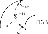
・図6は、例えば図1の装置で形成された繊維布帛が、ヘリックスに平坦に巻かれた場合にどのように変形するかを示す概略詳細図である;
・図7Aおよび7Bは、本発明の方法を実施するために繊維布帛をヘリックス状に巻く装置を示す概略図である;
・図8Aおよび8Bは、本発明の方法を実施するために繊維布帛をヘリックス状に巻く2つの別の装置を示す概略図である;
・図9は、本発明に従って環状の繊維構造物を製造する方法の実施を示す概略図である;
・図10は、本発明に従って環状の繊維構造物を製造する方法の別の実施を示す概略図である。
本発明の方法で用いられる繊維布帛は、相互に平行な繊維要素から成る2つの一方向性シートを重ねて一体に結合することにより製造される。
周知の方法において、一方向性シートは、トウ(tow)またはケーブル(cable)を広げて敷くことによって、あるいは以下の詳細な説明において説明するように異なるスプールから引き出された糸を平行に並べることによって得ることができる。
トウを広げることによって得られる一方向性シートから多軸性繊維布帛を製造する方法は、1997年3月28日に出願された、発明の名称が「多軸性繊維シートを製造する方法および装置」であるフランス国特許出願第97/03832号に説明されていることが理解されるであろう。この出願の内容は引用により本明細書に包含される。
図1は、糸から成る2つの一方向性のシート10、12を受け入れ、ストリップの長手方向に関して反対符号の角度(または対角)を形成する2つのシートを重ねることによって、ストリップの形状の布帛を形成する装置を非常に略して示しており、この例において、これらの角度は、+45°および−45°に等しい。
一方向性シート10および12を構成する繊維は、ストリップの形態の布帛について予定されている用途に応じて選択される材料から成る。繊維は、有機あるいは無機繊維、例えば炭素繊維もしくはセラミック繊維、または炭素繊維もしくはセラミック繊維の前駆体から成る繊維であってよい。2つのシートを構成する繊維は異なる種類のものであってもよいことが理解されるであろう。また、各シートにおいて種類の異なる繊維を使用することも可能である。
ストリップは、製造されるストリップの長手方向に対して+45°の角度にあるシートの連続的なセグメント10を導入し、これらのセグメントを前記の方向で並べることによって形成される。各セグメントは、それがストリップの一方の長手方向のエッジから他方の長手方向のエッジにかけて延びるような長さにわたって導入される。同様にして、シートの連続的なセグメント12が、製造されるストリップの長手方向に対して−45°の角度にて導入され、シートセグメント10上にシートセグメント12が配置されるようにして、並べられる。
図示した例において、シート10、12をそれぞれ構成する糸11、13には、同時に作動させられるスパイクの付いた2つのエンドレス・チェーン20、22の間で、張力がかけられている。シート10、12の端部は、各スプール(図示せず)から糸11、13を受け取って製造されるストリップの長手方向のエッジ間で前後に駆動されるキャリッジ14、16により、それぞれガイドされる。キャリッジの各ストロークの終わりに、シートは、対応するスパイクの付いたチェーンのスパイクの回りで回転させられる。スパイクの付いたチェーン20および22は、連続的なシートのセグメントが並べられるようにするために、導入されるシート10および12と同調して連続的にまたは不連続的に進められる。このタイプの装置は、例えば、米国特許第4 677 831号から知られており、従って、より詳細な説明は必要ではない。
シート10および12を重ねることにより形成されるストリップは、下流側の端部にてスパイクの付いたチェーン20および22から外されて、結合装置30へ進入する。図示した例において、結合は、形成されたストリップの幅全体にわたって延在するニードルボード32を用いてニードリングにより実施され、ストリップは穿孔したプレート34上を通過する。プレート34の孔はボード32のニードルと重なるように位置している。ニードルボード32におけるニードルの分布は、2つのシート間の結合が、例えば平行四辺形に変形可能である個々のステッチを規定できるよう、局在化されたニードリングを実施するように決定される。
得られたストリップ形状の繊維布帛50のシート間の結合は十分な強度を与え、スパイクの付いたチェーン20および22と同調してモーター48により駆動されるローラ38に当該布帛が巻き取られることを可能にする。結合装置30とローラ38との間で、ストリップ50の縁が回転するダイ36aおよび36bによってカットされる。
図2、3Aおよび3Bは、シート間を結合する好ましい異なる実施態様を示す。このバリエーションにおいて、結合はニードリングによってではなく、ニッティングによって実施される。スパイクの付いたチェーン20および22から外された、重ねられたシートは、ニッティング・マシン42に入る。ニッティング・マシン42は、ニッティングを実施する、即ち、2次元の構造物を、布帛50の一方の面から他方の面に進む糸を使って形成するものである(図2)。図3Aは、使用したニッティング・ステッチ44を詳細に示し、一方、図3Bおよび3Cはニッティングによって結合された布帛50の前面および裏面を示す。
図3Aに示すように、ニッティング・ステッチは、布帛50の長手方向において延びている絡み合ったループ44aを形成し、隣接する別のループを相互に連結するV字形状またはジグザグ形状の経路44bとともに複数の平行な列を形成する。布帛50は、前面に位置する経路44b(図3B)と裏面に位置するループ44a(図3C)との間に位置し、一方の面においてジグザグ・ステッチの外観を、他方の面においてチェーン・ステッチの外観をニットに与える。ニッティング・ステッチは、各シートにおいて複数の糸をカバーし、その数は選択したゲージによって決まる。
ジグザグ経路44bとループ44aとの間の結合ポイントは、例えば、図3Bおよび3CのポイントA、B、CおよびDのように、個々の変形可能なメッシュの頂点を規定する。即ち、この場合、ニッティング・ステッチにより規定されるメッシュは両方とも、変形可能な平行四辺形を形成しているシートの糸の間の組織点により規定されるメッシュのように、変形可能である。
図4は、シート間の結合がニッティングによって行われる別のバリエーションを示す。スパイクが付いたチェーン20および22から外された、重ねられたシートは、ニッティング・マシン46に入る。ニッティング・マシン46は、布帛50の長手方向のエッジに平行な複数のラインでシートを一体に結合する。
図5Aに示すように、各ニッティング・ステッチ48は、ループ48aが直線のセグメント48bを介してつながれているチェーン・ステッチ48であり、布帛50は、布帛の裏面で認識できるセグメント48b(図5B)とその前面で認識できるループ48a(図5C)との間に位置する。
図2および4の態様のニッティング・ステッチは、犠牲的材料、即ち、シートを構成する繊維を損傷することなく後で除去され得る材料から成るものであってよい。例えば、残渣を残すことなく熱により除去されるのに適した材料の糸、あるいは、溶媒によって除去されるのに適した材料の糸、例えば水溶性ポリビニルアルコール糸を使用することが可能である。
予定されている布帛の後の用途に適合する材料から成るニッティング糸を用いることもまた可能である。布帛が、複合材料のパーツの製造に使用される予備成形体を形成することになっている場合、ニッティングまたは縫合糸は、複合材料のマトリックス材料と適合する材料、即ち、好ましくは、マトリックスと同じ種類の材料、またはマトリックスと化学的に反応することなくマトリックスに混和できる材料から成る。
ニッティング、または実際には縫合により結合する他の方法もまた選択してよい。
得られたストリップ形状の布帛は、表面の変形(皺または糸の寄り)を生ぜしめることなく、平坦にヘリックス状に巻かれることを可能にする変形能のために特に好都合であり、これは、布帛50の基本メッシュ52が、選択された結合方法によって変形が制限されない変形可能な平行四辺形のように挙動することによるものであり、図2、3A、3Bおよび3Cに示すようなニッティングによる結合方法はこの点で好ましい方法である。
巻かれる間に(図6)、形成されるヘリックス(または螺旋体)の内径側に近接して位置する基本メッシュ52’は半径方向について延ばされて、長手方向について収縮する変形をし、一方、ヘリックスの外径側付近に位置する基本メッシュ52”は半径方向について収縮し、長手方向について延ばされる変形をする。その結果、内径側と外径側との間で、単位面積あたりの繊維密度は、実質的に一定なままであるか、あるいはほんの僅かだけ変化し、このことは、複合材料のパーツの製造に使用される均質な予備成形体を形成するのに特に有利である。図6において、鎖線54はストリップ50の当初の方向の1つの変形を示す。
結合がニッティングまたは縫合により行われる場合、布帛の糸で形成されている基本メッシュの変形は、ニッティングまたは縫合ステッチの変形を伴う。従って、図3A〜3Cのニッティング・ステッチについて、変形は、チェーン・ステッチのループを形成する糸の部分を長くせしめる、または短くせしめ、また、ジグザグの経路により形成されている角度を開く、または閉じる。
布帛50は、布帛を2つの環状のディスクまたはプレート60および62の間を通過させると同時に、ディスクの間に布帛の長手方向のエッジに沿って布帛を保持することにより、変形させながら、平坦なヘリックスに巻くことができる(図7A)。布帛は、例えば、ディスク60および62の内側の面に形成された円形のリブ64および66の間で、または少なくともディスクのうちの1つの内側の面で、そのエッジを挟むことにより保持することができる(図7B)。
別の態様において、布帛は、布帛を少なくとも1つの円錐台形のローラを通過させることによって、巻かれて変形させられる。使用されるローラの数およびそれらの頂点の角度は、所望とする変形度合いの関数として選択される。図8Aに示す例では、2つの同一の円錐台形のローラ70および72が用いられ、2つのローラは各自のモーター(図示せず)によって回転させられる。布帛は、2つのローラのうち少なくとも1つのローラの外周の一部に密着させられる。
図8Bの例において、布帛は、第1の回転する円錐台形ローラ74と平滑なプレッサー・プレート(presser plate;または押え板)75との間を通過させられ、そしてまた、第2の回転する円錐台形ローラ76と平滑なプレッサー・プレート77との間を通過させられる。ローラは各自のモーター(図示せず)によって回転させられ、ローラは摩擦により布帛を変形させる。
布帛を押し付ける単一の円錐台形ローラを用いることが可能である。そのような状況下において、ヘリックスの内径を規定する円錐台形ローラ上で布帛のエッジの一方によって描かれるのは、より小さい円である。
環状の繊維構造物は、布帛50をヘリックス状に巻くことにより形成される平坦なターンを重ね、巻くことを行っているときにニードリングによってターンを互いに結合させることにより、作ることができる(図9)。これは、繊維布帛を平坦なヘリックスに変形させながら、連続的に実施することができ、あるいは、それを一旦貯蔵した後に実施することができる。
例えば、図9に示すように2つのディスクの間を通過することによって変形させた布帛50は、ターンテーブル80上で重ねられた平坦なターンに巻かれる。ターンテーブル80は、支持体84に取り付けられた鉛直なシャフト82に取り付けられる。支持体84はまた、ベルト88を介してターンテーブル80をその鉛直な軸90の回りで回転させるために(矢印f1)、ターンテーブル80を駆動するモータ86を有する。
支持体84およびターンテーブル80を有するアセンブリーは、同じ軸90を有する固定された中央のガイド管92に沿って鉛直方向に移動できる。その上端では、管92はストリップをヘリックスに変形させる装置を支持している。支持体84は、垂直な入れ子式のロッド94の上にあり、支持体84の鉛直方向における移動は、1もしくは複数のアクチュエーター96の制御下にある。
ストリップ50が回転テーブル80の上に平坦に巻かれると、それは、ニードル102を有し鉛直方向に往復運動するように駆動されるボード100によってニードリングされる。ニードルボードは、クランクおよび連接棒式伝動機構を介してモーター104により駆動されて運動する。モーター104は支持体84によって支えられている。
ストリップ50は、実質的に一定である単位面積あたりの密度および深さにてニードリングされる。ストリップ50の環状ターンの全体のエリアにわたってニードル102のストロークの密度を一定とするために、ニードルボード100はセクター(扇形)形状であり、布の環状の層のセクターに対応しており、ニードルは前記セクターに均一に分布しており、一方、形成される構造物110を支持するターンテーブル80はそれ自体、一定の速度で回転させられる。
ニードリングの深さ、即ち、ニードルが各ストロークで構造物110の中に進入する距離は、実質的に一定に維持され、例えば、複数の重ねられた布の層によって形成される厚さに等しい。このために、ストリップ50がターンテーブル80の上で巻かれるにしたがって、ターンテーブルは適当な距離だけ下向きに鉛直に移動し、鉛直方向のストローク(または行程)の一端にて予備成形体の表面とニードルボードとの間の相対的な位置が変わらないことを確保する。予備成形体110が一旦形成されれば、ストリップ50の最後のターンが置かれた後、ニードリング・パス(またはニードリング動作)が複数回実施されると同時にターンテーブル80が続けて回転させられ、その結果、布の表面層における単位体積あたりのニードリングの密度が予備成形体の他の部分内と実質的に同じになる。これらの最後のニードリング・パスの少なくとも一部の間、先の段階の間のように、ターンテーブルを連続的に下向きに移動させることができる。予備成形体の支持体を連続的に低下させ、また、最後のニードリング・パスを実施することにより一定の深さにニードリングする原理は、公知であり、詳しくは上述したFR−A−2 584 106号の文献に説明されている。加えて、ターンテーブル80は保護層106で被覆され、ニードルはストリップ50の最初のターンをニードリングしている間、損傷されることなく当該保護層に進入できる。保護層106は、プラスチック材料(例えばポリ塩化ビニル)のシートで被覆されたベース・フェルト(例えばポリプロピレンのフェルト)で構成でき、それによりニードルの上昇行程の間に、ニードルがベース・フェルトから予備成形体110の中に繊維を引き入れることを防止している。
繊維構造物110の別の態様において、変形した布帛をヘリックス状に巻くことにより形成されるターンは、互いに貼り合わされ(または押し付けられ)、当該繊維構造物はベースプレート130およびトッププレート132を含む工具によって圧縮される(図10)。圧縮は、単位体積あたりの繊維密度を所望のものにするために実施される。従って、ターンは、ニードルボード134を使用してニードリングにより一体に結合することができ、ニードルボード134のニードル136はトッププレート132の開口部を経由して通過し、構造物110の厚さ全体にわたって貫通する。ボトムプレート130にもニードルと重なるように開口部を形成してよい。
上述のようにして得られる環状の繊維構造物は、複合材料から成る環状パーツ、例えばブレーキディスクを製造する際に予備成形体として用いるのに適している。
一方向性シートが犠牲的材料の糸により結合された場合、糸は、予備成形体を緻密化する前に、溶解または熱処理によって除去される。
得られた繊維構造物の繊維を構成する材料が複合材料の繊維補強材の前駆体である場合、前駆体は予備成形体が緻密化される前に、あるいは緻密化の前にその温度が上昇している間に、変換される。
予備成形体は、予備成形体のアクセス可能な小孔(ポア)内に所望の材料を構成する材料を析出させるために、液相プロセスまたは化学気相浸透によって常套的な方法で緻密化される。
上述の説明は、シートの長手方向に対して+45°および−45°の角度を形成している2つの一体に結合された一方向性シートから成る変形可能な繊維布帛を用いることに関するものであるが、本発明の方法を、2つの一方向性シートが、45°とは異なる絶対値、また、場合により互いに異なる絶対値を有する反対符号の角度を形成している変形可能なストリップを用いて実施してもよいことが理解されるであろう。そうとはいえ、メッシュの十分な変形能を維持するためには、前記の角度は30°〜60°の範囲内にある絶対値を有することが好ましく、また、変形可能なストリップにおいて対称を維持するために前記の角度は同じ絶対値を有することが好ましい。
更に、繊維ストリップは図1の載置装置から離れると同時にヘリックスに巻かれることが上記で仮定されている。1つのバリエーションにおいて、そして実際に好ましくは、形成される環状の予備成形体の半径の寸法があまり大きくない場合には、載置装置から離れる繊維のストリップは、長手方行に平行にカットすることによって、必ずしも同じ幅ではない複数の変形可能なストリップに最初に分けられる。The present invention relates to a method of manufacturing a preform (preform) for manufacturing an annular fiber structure, in particular, an annular part of a composite material.
The field to which the invention applies is in particular but not limited to the production of annular preforms for producing brake discs or clutch discs made of composite materials, in particular carbon-carbon (C / C) composite materials. Is not to be done.
Annular parts of composite material, such as brake discs or clutch discs, are composed of fiber reinforced structures or “preforms” that are densified with a matrix. With respect to the C / C composite disc, the preform is formed of carbon fibers or fibers of carbon precursors (precursors) that are converted to carbon by heat treatment after the preform is formed. . A specific carbon precursor available in fiber form is pre-oxidized polyacrylonitrile (PAN). Preforms use a liquid impregnation process, or chemical vapor infiltration (CVI), or in fact an elevated temperature, where a liquid carbon precursor (eg resin) is used and then the precursor is converted by heat treatment. It can be densified by either (calefaction; or heating). To achieve the elevated temperature, the preform is impregnated with the matrix precursor liquid and the preform is heated, for example by direct contact with the induction core or by direct coupling with the induction coil, thereby The precursor is vaporized and contacts the preform at the same time, penetrates and precipitates in the pores of the preform to form a matrix.
A known method of forming a fiber preform for a part made of composite material consists in two-dimensional fiber fabrics being stacked and needed together. For example, the fiber fabric may be a woven fabric. The fabric may optionally be coated with a fibrous web that provides fibers suitable for being moved by the needle through the stacked plies. This applies in particular when the fabric is formed of fibers, especially carbon fibers, that are difficult to needling without being cut. Such a method is described in particular in the documents FR-A-2 584 106 and FR-A-2 584 109, respectively, in which a method for producing a preform which is flat and a preform which is a rotating body are described. It is described in detail as a manufacturing method.
An annular preform for the disc can be cut out from a thick plate consisting of layers that are stacked horizontally and needled together. Therefore, the material loss can be as high as about 50%, which is very expensive for preforms made of carbon fibers or carbon precursor fibers.
In order to reduce this loss, the document EP-A-0 232 059 proposes forming a preform by stacking annular layers and needling them together. Each layer is formed by assembling a plurality of sectors together. Sectors are cut from a two-dimensional fabric. The material loss is less than if the entire ring is cut out, but it is still not negligible. In addition, there is a particular need to position the sectors accurately while ensuring that the sectors are offset (or shifted) from one layer to another to avoid overlapping lines separating the sectors. Therefore, it is quite difficult to implement and automate the method.
As described in the above-mentioned document FR-A-2 584 107, an annular preform is cut from a sleeve (or tube) formed by winding a strip of fabric around a mandrel and simultaneously It may be possible to needling. This method is relatively easy to implement without causing significant loss of fiber material. However, when applied to a friction disk, unlike the other embodiments described above, the plies of the preform are placed perpendicular to the friction surface, and in some cases such a configuration is not optimal.
Other known techniques for forming fiber preforms of annular parts made of composite materials are helix (spirals with a constant circle diameter) or spirals (spirals, spirals with progressively increasing or decreasing circle diameters) The use of a fabric product in the form of a strip (or strip) that is wound on a flat, superimposed turn. Cloth products. The fabric product may be a woven fabric composed of spiral warps and radial wefts.
As described in the documents FR-A-2 490 687 and FR-A-2 643 656, the spiral or helix shape is a truncated cone for the warp unwound from individual spools attached to the creel It is applied to the fabric by using a shaped roller. In fabrics made in this way, the spacing between the radial wefts increases between its inner diameter (inner circumference) and its outer diameter (outer circumference) in the width direction of the helical cross (helical cloth). ing.
In order to maintain the substantially uniform nature of the fabric over its entire width, the above two references insert additional wefts starting from the outer diameter of the fabric and extending only over a portion of the fabric width. Propose to do. This method obviously creates extra costs in the manufacture of the fabric and is a source of disadvantages that cannot be ignored. Another method described in patent application FR 95 14 000 is that between the inner and outer diameters, the decrease in weft density is almost compensated in terms of the density per unit volume of the preform. It is to increase the mass per unit area of the warp of the helical cross. This method is less expensive than increasing the density of the weft toward the outer diameter, but warp yarns with varying weight and / or mass per unit area between the inner and outer diameters of the fabric. Again, it is quite complicated because it needs to be used.
In yet another known technique, a fiber preform for an annular part made of composite material, and in particular for a brake disk, is formed by helically winding a flattened tubular braid. . The tubular blade may be in the form of a straight line, as described in the document EP-A-0 528 336. The blade is then deformed to wind in a helix (or spiral). To improve the dimensional stability of the preform and to compensate for density variations per unit area between the inner and outer diameter sides of the blade wound in a flat configuration Longitudinal yarns can be added during manufacture. In the document EP-A-0 683 261 it was also proposed to use a helical tubular blade. It makes it possible to overcome the limitations of the deformability of a straight-lined tubular blade when it is wound in a helix. Nevertheless, it is necessary to correct the density change per unit area by arranging multiple flat blades of small width between the inner and outer diameters or adding fibers in the longitudinal direction. . These methods make the production of preforms quite complex and therefore expensive, but do not provide a fully satisfactory solution to the problem of density variation per unit area.
Accordingly, the object of the present invention is for composite parts without causing mass disposal of the material and maintaining a substantially constant density per unit area between the inner and outer diameters of the structure. A method is provided that allows an annular preform to be produced.
Another object of the present invention is to provide a method that can achieve the same result as before, and the cost of implementation is considerably lower than the cost of the prior art method.
A method is provided for producing an annular fiber structure by winding a flat spiral (also referred to as a “helix”) of a deformable strip-shaped fiber fabric, the method comprising:
A deformable strip-shaped fabric composed of two stacked unidirectional sheets,
Each sheet is composed of mutually parallel fiber elements,
The fiber elements of one sheet form an opposite sign angle with respect to the direction of the fiber element of the other sheet and with respect to the longitudinal direction of the strip,
Two sheets are joined together to form a deformable basic mesh
Providing a deformable strip-shaped fiber fabric;
By changing the shape of the base mesh so that the radial dimension of the base mesh increases towards the inner diameter of the spiral bend (also referred to as a “turn”), the strip-shaped fabric becomes a spiral with a bend. Deform, thereby minimizing the change in mass per unit area between the inner and outer diameters of the bend; and
An annular shape in which the deformed curved portions are brought into contact with each other flatly so that the deformed fabric is wound as a flat spiral so that the radial dimension between the inner and outer diameters corresponds to the width of the deformed strip shape. Obtaining fiber structure
The process which exists in.
Advantageously, the direction formed by the two sheets relative to the longitudinal direction of the strip is preferably in the range from 30 ° to 60 ° in order to maintain the deformability of the basic mesh in the longitudinal and transverse directions An angle having an absolute value is formed. In a preferred embodiment, these angles are equal to + 45 ° and -45 °. The sheet retains the property that the base mesh is deformed at its apex, for example by stitching or knitting, using yarns that advance from one side of the fabric to the other, or in practice. Are joined together by pre-needling or localized needling.
Such fabric is particularly advantageous. It has a deformability that allows such fabrics to be wound as a flat helix with a substantially uniform distribution of fiber elements in the sheet without forming dense parts and wrinkles on the surface. This provides the helix with a density per unit area that can be maintained within the limits that allow for changes between the inner and outer diameters without requiring any correction.
Also advantageously, the flat superimposed turns formed by winding the fabric in a helix are joined together. Coupling between turns can be performed, for example, by needling. Needling is performed after winding and compressing the annulus as required, or while winding is taking place.
The strip-shaped fabric can be deformed by passing between the disks, with the longitudinal (or longitudinal) edge of the fabric being held between two rotating disks, for example by pinching, or alternatively The fabric can be deformed by passing it through at least one frustoconical roller.
Thus, while maintaining a fiber density that varies little between the inner and outer diameters without causing loss of fiber material and without the need to introduce additional elements as in prior art methods. An annular fiber structure can be formed, which makes it very easy to implement the present invention.
The invention will be better understood by reading the following description given by way of non-limiting description with reference to the accompanying drawings, in which:
FIG. 1 is a schematic view of an apparatus that allows a fibrous tissue to be formed into a deformable strip shape suitable for use in performing the method of the present invention;
Figures 2, 3A, 3B and 3C illustrate one method by which fiber fabrics suitable for use in carrying out the method of the present invention may be joined by knitting;
FIGS. 4, 5A, 5B and 5C show another method by which fiber fabrics suitable for carrying out the method of the invention can be joined by knitting;
FIG. 6 is a schematic detail drawing showing how a fiber fabric formed, for example, with the apparatus of FIG. 1 is deformed when wound flat on a helix;
Figures 7A and 7B are schematic diagrams showing an apparatus for helically winding a fiber fabric to perform the method of the present invention;
Figures 8A and 8B are schematic diagrams showing two alternative devices for helically winding a fiber fabric to perform the method of the present invention;
FIG. 9 is a schematic diagram illustrating the implementation of a method for producing an annular fiber structure according to the present invention;
FIG. 10 is a schematic diagram illustrating another implementation of a method of manufacturing an annular fiber structure in accordance with the present invention.
The fiber fabric used in the method of the present invention is manufactured by stacking and joining two unidirectional sheets made of mutually parallel fiber elements.
In a well-known manner, the unidirectional sheet aligns the yarns drawn from different spools in parallel by spreading a tow or cable, or as explained in the detailed description below. Can be obtained by:
A method for producing a multiaxial fiber fabric from a unidirectional sheet obtained by spreading a tow was filed on March 28, 1997. The name of the invention is “Method and apparatus for producing a multiaxial fiber sheet”. It will be understood that it is described in French patent application 97/03832, which is incorporated by reference herein in its entirety. The contents of this application are incorporated herein by reference.
FIG. 1 shows a strip-shaped fabric by receiving two
The fibers making up the
The strip is formed by introducing
In the illustrated example, the yarns 11 and 13 constituting the
The strip formed by overlapping the
The resulting bond between the sheets of the strip-shaped
2, 3A and 3B show different preferred embodiments for bonding between sheets. In this variation, the binding is performed by knitting rather than by needling. The overlaid sheets removed from the
As shown in FIG. 3A, the knitting stitch forms an intertwined loop 44a extending in the longitudinal direction of the
The connection points between the zigzag path 44b and the loop 44a define individual deformable mesh vertices, for example, points A, B, C and D in FIGS. 3B and 3C. That is, in this case, both the meshes defined by the knitting stitches are deformable, as are the meshes defined by the texture points between the yarns of the sheet forming the deformable parallelogram. .
FIG. 4 shows another variation in which joining between sheets is performed by knitting. The overlaid sheets removed from the
As shown in FIG. 5A, each knitting stitch 48 is a chain stitch 48 in which a
The knitting stitches of the embodiment of FIGS. 2 and 4 may consist of a sacrificial material, i.e. a material that can be removed later without damaging the fibers making up the sheet. For example, it is possible to use yarns of material suitable to be removed by heat without leaving a residue, or yarns of material suitable to be removed by a solvent, such as water-soluble polyvinyl alcohol yarns.
It is also possible to use a knitting yarn made of a material that is compatible with the intended subsequent use of the fabric. If the fabric is to form a preform that is used in the manufacture of a composite part, the knitting or suture is a material that is compatible with the composite matrix material, i.e., preferably with the matrix. It consists of the same type of material or material that is miscible with the matrix without chemically reacting with the matrix.
Other methods of joining by knitting or indeed by stitching may also be selected.
The resulting strip-shaped fabric is particularly advantageous due to its deformability, which allows it to be wound in a flat helix without causing surface deformations (wrinkles or yarns), This is due to the fact that the
While being wound (FIG. 6), the
When the connection is made by knitting or stitching, the deformation of the basic mesh formed of the fabric thread is accompanied by deformation of the knitting or stitching stitches. Thus, for the knitting stitches of FIGS. 3A-3C, the deformation lengthens or shortens the portion of the thread that forms the loop of the chain stitch, and opens the angle formed by the zigzag path, or close.
The
In another aspect, the fabric is wound and deformed by passing the fabric through at least one frustoconical roller. The number of rollers used and the angles of their vertices are selected as a function of the desired degree of deformation. In the example shown in FIG. 8A, two identical
In the example of FIG. 8B, the fabric is passed between a first rotating frustoconical roller 74 and a
It is possible to use a single frustoconical roller pressing the fabric. Under such circumstances, it is a smaller circle drawn by one of the fabric edges on a frustoconical roller that defines the inside diameter of the helix.
An annular fiber structure can be made by stacking flat turns formed by winding the
For example, as shown in FIG. 9, the
The assembly having the support 84 and the turntable 80 can move vertically along a fixed
When the
The
The depth of needling, i.e., the distance that the needle enters the
In another embodiment of the
The annular fiber structure obtained as described above is suitable for use as a preform when manufacturing an annular part made of a composite material, for example, a brake disk.
If the unidirectional sheets are joined by a sacrificial material yarn, the yarn is removed by dissolution or heat treatment before densifying the preform.
When the material constituting the fiber of the obtained fiber structure is a precursor of a composite fiber reinforcement, the temperature of the precursor is increased before the preform is densified or before densification. Will be converted while
The preform is densified in a conventional manner by liquid phase processes or chemical vapor infiltration to deposit the material comprising the desired material within the pores accessible to the preform. .
The above description relates to the use of a deformable fiber fabric consisting of two integrally bonded unidirectional sheets forming an angle of + 45 ° and −45 ° with the longitudinal direction of the sheet. However, the method of the present invention uses a deformable strip in which two unidirectional sheets form opposite sign angles having absolute values different from 45 ° and possibly different absolute values. It will be understood that it may be implemented. Nevertheless, in order to maintain sufficient deformability of the mesh, it is preferred that the angle has an absolute value in the range of 30 ° to 60 ° and maintain symmetry in the deformable strip. In order to do so, the angles preferably have the same absolute value.
Furthermore, it has been assumed above that the fiber strip is wound into a helix as soon as it leaves the mounting device of FIG. In one variation, and in practice, preferably, if the radial dimension of the formed annular preform is not too large, the strip of fiber leaving the mounting device should be cut parallel to the longitudinal direction. Is first divided into a plurality of deformable strips that are not necessarily the same width.
Claims (17)
(i)2つの重ねられた一方向性シートから成る変形可能でフラットなストリップ形態の繊維布帛であって、各シートは相互に平行な繊維要素により構成され、一方のシートの繊維要素の向きは、他方のシートの繊維要素の向きに対して、および、ストリップの長手方向に対して、交差する反対符号の角度を形成しており、2つのシートが一体に結合されて繊維布帛の変形可能な基本メッシュを形成している、変形可能でフラットなストリップ形態の繊維布帛を供給する工程;
(ii)ストリップ形態の布帛をそのフラットな面を実質的に含む平面内で変形させて巻いて実質的にフラットな螺旋体とし、基本メッシュの形状を変化させ、前記螺旋体の半径方向についての基本メッシュの寸法を螺旋体のターンの内径の方へ向かって増加させ、それによりターンの内径側と外径側との間で単位面積あたりの質量の変化を最小限とする工程;ならびに
(iii)前記ストリップ形態の布帛のフラットな螺旋体の1つのターンにおける一方の面と、それに隣る螺旋体のターンにおける他方の面とを互いに接触させることによって、繊維布帛の螺旋体を重ね合わせ、それにより内径側と外径側との間の半径方向の寸法が、変形させたストリップ形態の布帛の幅に対応する、環状の繊維構造物を得る工程
を含んでなる方法。 The fiber fabric of a deformable flat strip-shaped state by winding the flat surface in a plane substantially including a method of fabricating an annular fiber structure by a flat spiral:
(I) a fiber fabric of a deformable flat strip-shaped state consisting of two superposed unidirectional sheets, each sheet is constituted by parallel fiber elements mutually, the orientation of the fiber elements of one sheet Forms an opposite sign of the angle with respect to the direction of the fiber elements of the other sheet and with respect to the longitudinal direction of the strip, so that the two sheets can be joined together to deform the fiber fabric. supplying such form the base mesh, a fiber fabric of a deformable flat strip-shaped state;
(Ii) A strip-shaped fabric is deformed in a plane substantially including its flat surface and wound to form a substantially flat spiral body, the shape of the basic mesh is changed, and the basic mesh in the radial direction of the spiral body increases toward the dimensions towards the inside diameter of the spiral turns, whereby steps to minimize the change in mass per unit area between the inner diameter side and outer diameter side of the turn; and (iii) the strip The fabric fabric spiral is overlapped by bringing one surface of one turn of the flat spiral of the fabric of the form into contact with the other surface of the turn of the adjacent spiral so that the inner and outer diameters are overlapped. how the radial dimension between the side corresponds to the width of the fabric strip-shaped state that is deformed, consisting Nde including a step <br/> obtaining a cyclic fiber structure.
Applications Claiming Priority (3)
| Application Number | Priority Date | Filing Date | Title |
|---|---|---|---|
| FR97/03833 | 1997-03-28 | ||
| FR9703833A FR2761379B1 (en) | 1997-03-28 | 1997-03-28 | PROCESS FOR PRODUCING ANNULAR FIBROUS STRUCTURES, PARTICULARLY FOR THE MANUFACTURE OF COMPOSITE MATERIAL PARTS |
| PCT/FR1998/000598 WO1998044182A1 (en) | 1997-03-28 | 1998-03-25 | Method for producing ring-shaped fibrous structures, in particular for making parts in composite material |
Publications (3)
| Publication Number | Publication Date |
|---|---|
| JP2001517272A JP2001517272A (en) | 2001-10-02 |
| JP2001517272A5 JP2001517272A5 (en) | 2005-11-10 |
| JP4083815B2 true JP4083815B2 (en) | 2008-04-30 |
Family
ID=9505293
Family Applications (1)
| Application Number | Title | Priority Date | Filing Date |
|---|---|---|---|
| JP54122398A Expired - Fee Related JP4083815B2 (en) | 1997-03-28 | 1998-03-25 | Method for manufacturing a ring-shaped fiber structure forming a composite part |
Country Status (11)
| Country | Link |
|---|---|
| US (1) | US6319348B1 (en) |
| EP (1) | EP0970271B1 (en) |
| JP (1) | JP4083815B2 (en) |
| KR (1) | KR100501632B1 (en) |
| CA (1) | CA2285375C (en) |
| DE (1) | DE69802508T2 (en) |
| ES (1) | ES2167888T3 (en) |
| FR (1) | FR2761379B1 (en) |
| RU (1) | RU2176296C2 (en) |
| UA (1) | UA54502C2 (en) |
| WO (1) | WO1998044182A1 (en) |
Families Citing this family (27)
| Publication number | Priority date | Publication date | Assignee | Title |
|---|---|---|---|---|
| FR2761380B1 (en) * | 1997-03-28 | 1999-07-02 | Europ Propulsion | METHOD AND MACHINE FOR PRODUCING MULTIAXIAL FIBROUS MATS |
| EP1187950A2 (en) * | 1999-11-24 | 2002-03-20 | Snecma Moteurs | Method for making a bowl in thermostructural composite material, resulting bowl and use of same as crucible support |
| FR2812889B1 (en) * | 2000-08-11 | 2002-11-15 | Snecma Moteurs | PROCESS FOR THE MANUFACTURE OF A MONOBLOCK BOWL IN THERMOSTRUCTURAL COMPOSITE MATERIAL, PARTICULARLY FOR A SILICON PRODUCTION INSTALLATION, AND BOWL AS OBTAINED BY THIS PROCESS |
| US6521152B1 (en) * | 2000-03-16 | 2003-02-18 | Honeywell International Inc. | Method for forming fiber reinforced composite parts |
| FR2818666B1 (en) | 2000-12-27 | 2004-02-06 | Snecma Moteurs | PROTECTION OF A BOWL OF CARBON MATERIAL, IN PARTICULAR OF A C / C COMPOSITE, FOR RECEIVING A CRUCIBLE, SUCH AS A SILICA CRUCIBLE FOR DRAWING SILICON |
| FR2824085B1 (en) * | 2001-04-30 | 2003-08-01 | Messier Bugatti | CIRCULAR NEEDLE MACHINE PROVIDED WITH AN AUTOMATIC PREFORM DEVICE |
| FR2824086B1 (en) * | 2001-04-30 | 2003-08-01 | Messier Bugatti | SMOOTH TABLE CIRCULAR NEEDLE MACHINE |
| FR2824084B1 (en) * | 2001-04-30 | 2003-08-01 | Messier Bugatti | NEEDLE FEEDER BY CONTINUOUS SPIRAL BAND |
| EP1529865B1 (en) * | 2002-08-12 | 2009-01-28 | Shikibo Ltd. | Preform precursor for fiber-reinforced composite material, preform for fiber-reinforced composite material, and method of manufacturing the precursor and the preform |
| US7384585B2 (en) * | 2003-01-14 | 2008-06-10 | Shikibo Ltd. | Method for producing dry preform for composite material |
| US20040231211A1 (en) * | 2003-05-02 | 2004-11-25 | Johnson John R. | Three-dimensional automobile badge |
| DE102005034401B4 (en) * | 2005-07-22 | 2008-02-14 | Airbus Deutschland Gmbh | Process for the production of single or multilayer fiber preforms |
| CN101326050B (en) * | 2005-12-08 | 2012-07-04 | 纳幕尔杜邦公司 | Multiaxial fabric |
| DE602006010431D1 (en) * | 2005-12-16 | 2009-12-24 | Du Pont | THERMAL PERFORMANCE CLOTHING ACCESSORIES WITH PIPE AND ARAMID FIBER OUTSIDE |
| FR2909920B1 (en) * | 2006-12-15 | 2009-03-20 | Snecma Propulsion Solide Sa | METHOD FOR PRODUCING A CARTER-DIVERGENT ASSEMBLY |
| FR2911524B1 (en) * | 2007-01-23 | 2009-08-21 | Snecma Sa | TUBULAR PIECE COMPRISING A METALLIC MATRIX COMPOSITE INSERT. |
| DE102007025556B4 (en) * | 2007-05-31 | 2010-06-17 | Eurocopter Deutschland Gmbh | Process for the production of components from fiber reinforced plastics |
| US9186850B2 (en) * | 2009-10-28 | 2015-11-17 | Albany Engineered Composites, Inc. | Fiber preform, fiber reinforced composite, and method of making thereof |
| US20110275266A1 (en) | 2010-05-05 | 2011-11-10 | Goodrich Corporation | System and method for textile positioning |
| WO2013036848A1 (en) * | 2011-09-09 | 2013-03-14 | Nicolon Corporation, doing business as TenCate Geosynthetics North America | Multi-axial fabric |
| JP5847033B2 (en) | 2012-07-19 | 2016-01-20 | 株式会社Shindo | Carbon fiber stitch substrate and wet prepreg using the same |
| US9045846B2 (en) | 2012-12-05 | 2015-06-02 | Goodrich Corporation | Spiral textile and system for weaving the same |
| KR101380045B1 (en) * | 2013-04-04 | 2014-04-04 | 김형진 | Textile manufacturing device |
| US9309613B1 (en) * | 2014-11-03 | 2016-04-12 | Goodrich Corporation | System and method to fabricate helical fabric |
| US11746059B2 (en) * | 2020-02-26 | 2023-09-05 | General Electric Companhy | Induction melt infiltration processing of ceramic matrix composite components |
| CN112481835B (en) * | 2020-11-30 | 2022-08-23 | 厦门当盛新材料有限公司 | Production method of polyethylene film |
| CN113086760B (en) * | 2021-03-24 | 2022-11-01 | 哈尔滨复合材料设备开发有限公司 | Fiber composite material endless chain winding equipment and use method thereof |
Family Cites Families (11)
| Publication number | Priority date | Publication date | Assignee | Title |
|---|---|---|---|---|
| US3000432A (en) * | 1955-07-01 | 1961-09-19 | Neil L Olken | Fabric and method of and apparatus for producing the same |
| FR2490687A1 (en) * | 1980-09-24 | 1982-03-26 | Coisne Lambert Ets | Helical fabric - for e.g. brake linings, rotary discs, etc. |
| DE3343048A1 (en) * | 1983-11-28 | 1985-06-05 | Liba Maschinenfabrik Gmbh, 8674 Naila | METHOD AND DEVICE FOR LAYING CROSSFITTING THREADS FOR A CHAIN KNITTING MACHINE |
| FR2643656B1 (en) * | 1989-02-27 | 1992-02-14 | Brochier Sa | SPIRAL-SHAPED TEXTILE STRUCTURE, PROCESS FOR PRODUCING THE SAME, AND CORRESPONDING WEAVING MACHINE |
| US5173314A (en) * | 1989-08-28 | 1992-12-22 | Fuji Jukogyo Kabushiki Kaisha | Apparatus for bending and forming a composite material sheet |
| US5217770A (en) * | 1991-08-15 | 1993-06-08 | The B. F. Goodrich Company | Braided shaped filamentary structures and methods of making |
| GB9215028D0 (en) * | 1992-07-15 | 1992-08-26 | Fitzgerald Marcus B | Construction of fabric web of fibres |
| US5662855A (en) * | 1994-05-17 | 1997-09-02 | The B.F. Goodrich Company | Method of making near net shaped fibrous structures |
| US5546880A (en) * | 1994-12-29 | 1996-08-20 | The Bf Goodrich Company | Annular filamentary structures and methods of making |
| FR2741634B1 (en) * | 1995-11-27 | 1998-04-17 | Europ Propulsion | PROCESS FOR THE REALIZATION OF FIBROUS PREFORMS INTENDED FOR THE MANUFACTURE OF ANNULAR PIECES IN COMPOSITE MATERIAL |
| US5952075A (en) * | 1997-09-08 | 1999-09-14 | Fiberite, Inc. | Needled near netshape carbon preforms having polar woven substrates and methods of producing same |
-
1997
- 1997-03-28 FR FR9703833A patent/FR2761379B1/en not_active Expired - Fee Related
-
1998
- 1998-03-25 CA CA002285375A patent/CA2285375C/en not_active Expired - Fee Related
- 1998-03-25 EP EP98917227A patent/EP0970271B1/en not_active Expired - Lifetime
- 1998-03-25 DE DE69802508T patent/DE69802508T2/en not_active Expired - Lifetime
- 1998-03-25 ES ES98917227T patent/ES2167888T3/en not_active Expired - Lifetime
- 1998-03-25 US US09/381,943 patent/US6319348B1/en not_active Expired - Lifetime
- 1998-03-25 WO PCT/FR1998/000598 patent/WO1998044182A1/en active IP Right Grant
- 1998-03-25 JP JP54122398A patent/JP4083815B2/en not_active Expired - Fee Related
- 1998-03-25 KR KR10-1999-7008866A patent/KR100501632B1/en not_active IP Right Cessation
- 1998-03-25 RU RU99122690/12A patent/RU2176296C2/en active
- 1998-03-25 UA UA99105812A patent/UA54502C2/en unknown
Also Published As
| Publication number | Publication date |
|---|---|
| CA2285375A1 (en) | 1998-10-08 |
| DE69802508T2 (en) | 2002-08-22 |
| ES2167888T3 (en) | 2002-05-16 |
| CA2285375C (en) | 2007-06-19 |
| EP0970271A1 (en) | 2000-01-12 |
| KR100501632B1 (en) | 2005-07-18 |
| EP0970271B1 (en) | 2001-11-14 |
| KR20010005794A (en) | 2001-01-15 |
| US6319348B1 (en) | 2001-11-20 |
| WO1998044182A1 (en) | 1998-10-08 |
| FR2761379B1 (en) | 1999-07-09 |
| JP2001517272A (en) | 2001-10-02 |
| RU2176296C2 (en) | 2001-11-27 |
| FR2761379A1 (en) | 1998-10-02 |
| DE69802508D1 (en) | 2001-12-20 |
| UA54502C2 (en) | 2003-03-17 |
Similar Documents
| Publication | Publication Date | Title |
|---|---|---|
| JP4083815B2 (en) | Method for manufacturing a ring-shaped fiber structure forming a composite part | |
| KR100447343B1 (en) | Manufacturing method of fiber preform used for annular part manufacturing of synthetic material | |
| EP0528336B1 (en) | Braided shaped filamentary structures and method of making | |
| TWI334893B (en) | A method of making a helical two-dimensional fiber sheet and an installation for fabricating a helical two-dimentional fiber sheet | |
| US5662855A (en) | Method of making near net shaped fibrous structures | |
| US4621662A (en) | Process and apparatus for manufacturing axi-symmetrical three-dimensional structures | |
| EP0721835B1 (en) | Shaped filamentary structures and methods of making | |
| JP4875095B2 (en) | Fabrication of three-dimensional annular fiber structure | |
| JPS626957A (en) | Method for producing three-dimensional axially symmetric structure by puncturing fibrous material layer and fiber material used therein | |
| EP0546001B1 (en) | Production of shaped filamentary structures | |
| RU2169805C2 (en) | Methods and apparatus for manufacture of annular members from composite materials and preforms for these members | |
| KR20000070988A (en) | Making an annular fiber preform by winding a sliver | |
| JPH08312699A (en) | Near-net-shaped fibrous structure and manufacture thereof |
Legal Events
| Date | Code | Title | Description |
|---|---|---|---|
| A521 | Request for written amendment filed |
Free format text: JAPANESE INTERMEDIATE CODE: A523 Effective date: 20050315 |
|
| A621 | Written request for application examination |
Free format text: JAPANESE INTERMEDIATE CODE: A621 Effective date: 20050315 |
|
| A131 | Notification of reasons for refusal |
Free format text: JAPANESE INTERMEDIATE CODE: A131 Effective date: 20060926 |
|
| A601 | Written request for extension of time |
Free format text: JAPANESE INTERMEDIATE CODE: A601 Effective date: 20061221 |
|
| A602 | Written permission of extension of time |
Free format text: JAPANESE INTERMEDIATE CODE: A602 Effective date: 20070219 |
|
| A521 | Request for written amendment filed |
Free format text: JAPANESE INTERMEDIATE CODE: A523 Effective date: 20070323 |
|
| A131 | Notification of reasons for refusal |
Free format text: JAPANESE INTERMEDIATE CODE: A131 Effective date: 20070515 |
|
| A601 | Written request for extension of time |
Free format text: JAPANESE INTERMEDIATE CODE: A601 Effective date: 20070807 |
|
| A602 | Written permission of extension of time |
Free format text: JAPANESE INTERMEDIATE CODE: A602 Effective date: 20070914 |
|
| A521 | Request for written amendment filed |
Free format text: JAPANESE INTERMEDIATE CODE: A523 Effective date: 20071114 |
|
| TRDD | Decision of grant or rejection written | ||
| A01 | Written decision to grant a patent or to grant a registration (utility model) |
Free format text: JAPANESE INTERMEDIATE CODE: A01 Effective date: 20080115 |
|
| A61 | First payment of annual fees (during grant procedure) |
Free format text: JAPANESE INTERMEDIATE CODE: A61 Effective date: 20080214 |
|
| R150 | Certificate of patent or registration of utility model |
Free format text: JAPANESE INTERMEDIATE CODE: R150 |
|
| FPAY | Renewal fee payment (event date is renewal date of database) |
Free format text: PAYMENT UNTIL: 20110222 Year of fee payment: 3 |
|
| S111 | Request for change of ownership or part of ownership |
Free format text: JAPANESE INTERMEDIATE CODE: R313113 |
|
| FPAY | Renewal fee payment (event date is renewal date of database) |
Free format text: PAYMENT UNTIL: 20110222 Year of fee payment: 3 |
|
| R350 | Written notification of registration of transfer |
Free format text: JAPANESE INTERMEDIATE CODE: R350 |
|
| LAPS | Cancellation because of no payment of annual fees |