JP4083365B2 - Brushless motor - Google Patents
Brushless motor Download PDFInfo
- Publication number
- JP4083365B2 JP4083365B2 JP2000085392A JP2000085392A JP4083365B2 JP 4083365 B2 JP4083365 B2 JP 4083365B2 JP 2000085392 A JP2000085392 A JP 2000085392A JP 2000085392 A JP2000085392 A JP 2000085392A JP 4083365 B2 JP4083365 B2 JP 4083365B2
- Authority
- JP
- Japan
- Prior art keywords
- bus bar
- terminal
- circuit
- brushless motor
- inner case
- Prior art date
- Legal status (The legal status is an assumption and is not a legal conclusion. Google has not performed a legal analysis and makes no representation as to the accuracy of the status listed.)
- Expired - Fee Related
Links
Images


Description
【0001】
【発明の属する技術分野】
本発明は、ブラシレスモータに関するものである。
【0002】
【従来の技術】
図9は、従来品の一例を示す断面図である。このブラシレスモータaは、特開平9−191625号公報に記載されたものであり、回路保護ケースb内に、モータシャフトcを回転させる駆動回路dが収容されている。
【0003】
この駆動回路dは、所定の配線パターンを有する回路基板eに形成されており、一般的に、供給電力からサージを除去するフィルタ回路d1と、このフィルタ回路d1を通過した電流のステータfへの電流経路を所定時期に切り換えてステータfの磁界を制御する制御回路d2とを備えている。この制御回路d2は、ステータfのコイルf1を流れる電流のフィルタ回路d1からの電流経路を切り換えるスイッチング素子gを備え、このスイッチング素子gは、その発熱を回路保護ケースb外へ放熱するヒートシンクhに取り付けられている。
【0004】
制御回路d2とステータfのコイルf1とは、このコイルf1に電気的に接続されたターミナルピンiと、回路基板eに実装されたジョイントバーjと、このジョイントバーjとターミナルピンiとを電気的に接続する接続用バスバーkとを介して電気的に接続されている。
【0005】
【発明が解決しようとする課題】
このブラシレスモータaでは、制御回路d2とコイルf1との電気的な接続にターミナルピンi,ジョイントバーj,接続用バスバーkの3部品が必要であり、制御回路d2とコイルf1との電気接続のための部品点数が多い。このため、制御回路d2とコイルf1との電気接続のための作業工数が多くなり、歩留まりの低下と製造コストの上昇とを招いてしまう。
【0006】
しかも、ジョイントバーjとターミナルピンiとに接続用バスバーkを溶接等で接続する際には、接続用バスバーkを所定位置に保持する保持治具が必要になる。このため、接続用バスバーkの接続作業の作業効率が低くなり、この点でも製造コストの上昇を招いてしまう。
【0007】
そこで、本発明では、従来品と比べて、ステータのコイルと制御回路との電気接続のための作業工数を減少させることができ、接続用バスバーの接続時に接続用バスバーを所定位置に保持する保持治具を不要にすることもでき、その結果、歩留まりの向上と製造コストの低減とを図ることができるブラシレスモータを提供することを課題としている。
【0008】
【課題を解決するための手段】
請求項1記載の発明は、供給電力からサージを除去するフィルタ回路と、該フィルタ回路を通過した電流のステータへの電流経路を所定時期に切り換えてステータの磁界を制御する制御回路とが回路保護ケース内に収容され、ステータのコイルに電気的に接続されたターミナルピンと、前記制御回路とが接続用バスバーを介して電気的に接続されているブラシレスモータにおいて、フィルタ回路は、配線用バスバーが組み付けられ回路保護ケースに固定され当該回路保護ケースの内部空間内の所定位置に配置された合成樹脂製のインナーケースに形成され、制御回路は、所定の配線パターンを備えインナーケースに固定された回路基板に形成され、接続用バスバーは、インナーケースに組み付けられて回路保護ケース内の所定位置に配置されていると共に、一端が回路基板に半田付けされ、他端がターミナルピンに電気的に接続されていることを特徴としている。
【0009】
請求項2記載の発明は、請求項1記載のブラシレスモータであって、配線用バスバーは、コネクタによって電気的に接続されるコネクタ端子を少なくとも2本備え、該コネクタ端子は、配線用バスバーのバスバー本体とは別体に形成され、該バスバー本体に固着されていることを特徴としている。
【0010】
請求項3記載の発明は、請求項2記載のブラシレスモータであって、配線用バスバーは、インナーケースにインサート成形によって組み付けられ、コネクタ端子とバスバー本体との固着箇所がインナーケースの合成樹脂中に埋め込まれていることを特徴としている。
【0011】
【発明の効果】
請求項1記載の発明によれば、接続用バスバーは、一端が回路基板に半田付けされ、他端がターミナルピンに電気的に接続されているので、図9図示の従来品では必要なジョイントバーを不要にすることができる。従って、図9図示の従来品と比べて、ステータのコイルと制御回路との電気接続のための作業工数を減少させることができ、歩留まりの向上と製造コストの低減とを図ることができる。
【0012】
しかも、接続用バスバーは、回路保護ケースに固定されたインナーケースに組み付けられて回路保護ケース内の所定位置に配置されているので、回路保護ケースにインナーケースを固定した後に接続用バスバーとターミナルピンとの接続を行うことにより、この接続の際には、インナーケースによって接続用バスバーを所定位置に保持することができる。従って、接続用バスバーの接続時に接続用バスバーを所定位置に保持する保持治具を不要にすることができ、この保持治具が必要な図9図示の従来品と比べて、接続用バスバーの接続作業の作業効率を向上させることができ、この点でも製造コストの低減を図ることができる。
【0013】
請求項2記載の発明によれば、配線用バスバーの少なくとも2本のコネクタ端子は、配線用バスバーのバスバー本体とは別体に形成され、該バスバー本体に固着されているので、コネクタ端子と結合される相手側端子の形状や配置が変更された場合であっても、コネクタ端子の形状の変更、バスバー本体に対するコネクタ端子の固着位置の変更等によって対処することができる。従って、コネクタの種類に応じた対応が容易で、かつ、その対応に用する変更を低コストで実現することができる。
【0014】
また、コネクタ端子に酸化防止用のメッキ処理を施す場合には、コネクタ端子のみにメッキ処理を容易に施すこともできる。これに対し、配線用バスバーのバスバー本体とコネクタ端子とが一体成形されているものでは、配線用バスバーの全体メッキかコネクタ端子の部分メッキが必要となる。従って、配線用バスバーのバスバー本体とコネクタ端子とが一体成形されているものと比べて、酸化防止用のメッキ処理のコスト低減を図ることもできる。
【0015】
請求項3記載の発明によれば、配線用バスバーは、コネクタ端子とバスバー本体との固着箇所がインナーケースの合成樹脂中に埋め込まれているので、コネクタ端子とバスバー本体との固着箇所をインナーケースの合成樹脂によって補強することができると共に、その固着箇所の酸化を防止して固着箇所の信頼性を向上させることもできる。
【0016】
【発明の実施の形態】
図1は、本発明の実施の形態の一例を示す断面図である。このブラシレスモータ1は、自動車用空気調和装置のブロアファンモータとして使用されるものであり、モータシャフト2の上端部に送風用のシロッコファンが取り付けられるようになっている。モータシャフト2は、上下一対の軸受部3,3を介してハウジング4に回転自在に支持されている。
【0017】
このハウジング4には、モータシャフト2下端側に位置する軸受部3が設けられていると共に、外周面にステータ5が組み付けられている。このステータ5は、金属薄板を積層させたコア5aと、このコア5aに組み付けられた上下一対の電気絶縁体5b,5bと、これらの電気絶縁体5bを介在させてコア5aに巻かれたコイル5cとを備えている。コア5aの上部に組み付けられた電気絶縁体5bには、モータシャフト2上端側に位置する軸受部3が設けられている。
【0018】
ステータ5の外側には、ステータ5に近接して4個の永久磁石6が略等間隔に配置されている。これらの永久磁石6を保持するヨーク7は、ステータ5を覆ってモータシャフト2の上部に固定されている。ハウジング4の下端部に設けられたフランジ部4aには、防振ゴム8を介在させて合成樹脂製の回路保護ケース10がビス止め固定されている。この回路保護ケース10は、モータシャフト2上端側に位置するアッパーケース11と、モータシャフト2下端側に位置するロアケース12とからなっている。
【0019】
回路保護ケース10内には、モータシャフト2の下端部に固定されたセンサ磁石13と、モータシャフト2を回転させる駆動回路14とが収容されている。センサ磁石13は、各永久磁石6の配設位置に対応する部位が、その対応する永久磁石6と同極に着磁されている。駆動回路14は、供給電力からサージを除去するフィルタ回路20と、このフィルタ回路20を通過した電流のステータ5への電流経路を所定時期に切り換えてステータ5の磁界を制御する制御回路30とを備えている。
【0020】
図2は、図1に示すものの駆動回路を示す平面図である。図1,図2に示すように、制御回路30は、所定の配線パターンを備えた回路基板31に形成されている。この回路基板31には、フィルタ回路20を通過してステータ5のコイル5cを流れる電流のフィルタ回路20からの電流経路を切り換えるスイッチング素子32、このスイッチング素子32の電流経路切換時期を制御する制御IC33、センサ磁石13と協働して永久磁石6の回転位置を検出するホール素子(図示省略)、電解コンデンサ34等の電気部品が実装されている。
【0021】
スイッチング素子32は、その発熱を回路保護ケース10外へ放熱する放熱フィン35aを備えたアルミ製のヒートシンク35に、スプリング部材36によって圧接されている。ヒートシンク35は、門型の形状を有し、回路基板31に固定されている。スプリング部材36は、スイッチング素子32の下方に配置され回路基板31に固定されている。
【0022】
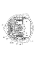
図3は、図1に示すものからロアケースを取り外した状態を示す下面図である。図4は、図1に示すもののフィルタ回路を示す平面図である。図3,図4に示すように、フィルタ回路20は、配線用バスバー40がインサート成形によって組み付けられた合成樹脂製のインナーケース21に、電解コンデンサ22,コモンモードチョークコイル23,バリスタ24,ヒューズ部材25等の電気部品が実装されて形成されている。
【0023】
図1〜図4に示すように、インナーケース21は、アッパーケース11頂壁に垂設された取付ボス部にビス固定されて回路保護ケース10内の所定位置に配置されている。回路基板31は、インナーケース21に取り付けられ、インナーケース21を介してアッパーケース11に固定されており、インナーケース21の上方に位置している。
【0024】
インナーケース21には、3本の接続用バスバー15もインサート成形によって組み付けられている。各接続用バスバー15は、ステータ5のコイル5cに溶接されて電気的に接続されアッパーケース11を貫通するターミナルピン16と、制御回路30とを電気的に接続しており、ステータ5からの振動が制御回路30の回路基板31に伝わるのを防止するU字状の防振構造(図1参照)を備えている。
【0025】
そして、各接続用バスバー15は、インナーケース21に組み付けられて回路保護ケース10内の所定位置に配置されていると共に、一端が上方へ折曲され回路基板31のスルーホール37(図2参照)に挿通されて回路基板31に半田付けされ、他端が下方へ折曲されてターミナルピン16の下端部に溶接されている。この溶接は抵抗溶接によって行われている。接続用バスバー15とターミナルピン16との溶接は、インナーケース21を回路基板31と共にアッパーケース11に固定した後に行われる。
【0026】
回路基板31には、その所定位置に、配線用バスバー40の所定部位が上方へ折曲されて半田付けされている。この半田付けによって、フィルタ回路20と制御回路30とは電気的に接続されている。
【0027】
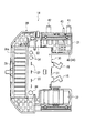
図5は、インナーケースへの組付前の配線用バスバー及び接続用バスバーを示す下面図である。図6は、図5に示すもののコネクタ端子を示す下面図であり、(a)はアース端子及びプラス端子を示し、(b)は信号端子を示している。
【0028】
図5に示すように、配線用バスバー40と接続用バスバー15とは、ハッチングを施した複数の架橋箇所で互いに連結されており、この連結された状態でインサート成形され、インサート成形後に、架橋箇所が除去され所定の部位が所定の方向へ折曲されるようになっている。
【0029】
図5,図6に示すように、配線用バスバー40は、コネクタによって電気的に接続されるコネクタ端子として、車載電源から電力を受電するプラス端子41と、車体と電気的に接続されるアース端子42と、外部制御信号を受信する信号端子43とを備えている。これらの端子41,42,43は、配線用バスバー40のバスバー本体44に溶接によって固着されている。そして、これらの端子41,42,43とバスバー本体44との溶接箇所は、インナーケース21のインサート成形時に、インナーケース21を形成する合成樹脂中に埋め込まれるようになっている。
【0030】
プラス端子41が溶接されたバスバー本体44は、信号端子43が溶接された信号端子43用のバスバー本体44によって分断されている。しかし、この分断された箇所は、ヒューズ部材25(図4参照)によって架橋されるようになっている。信号端子43は、信号端子43用のバスバー本体44を介して制御回路30の回路基板31と電気的に接続されるようになっている。そして、信号端子43には、プラス端子41及びアース端子42と比べて微弱な電流が流れるので、コネクタ接続される相手側端子との酸化膜による導通不良を防止する酸化防止用のメッキ処理が施されている。
【0031】
図7は、図5に示すものとは異なるものの一例を示す下面図である。図8は、図7に示すもののコネクタ端子を示す下面図であり、(a)はアース端子、(b)は信号端子、(c)はプラス端子をそれぞれ示している。図7,図8に示すように、図7に示すものは、配線用バスバー40′のプラス端子41′,アース端子42′,信号端子43′が図5に示すものとは異なっている。
【0032】
すなわち、これらの端子41′,42′,43′は、図5に示すもののプラス端子41,アース端子42,信号端子43とは形状と、バスバー本体44への取付位置とが異なっている。従って、図7に示すものでは、バスバー本体44及び接続用バスバー15は、図5に示すものと共用することができる。
【0033】
なお、配線用バスバー40′でも、配線用バスバー40と同様、プラス端子41′,アース端子42′,信号端子43′は、バスバー本体44に溶接によって固着され、インナーケース21のインサート成形時に、バスバー本体44との溶接箇所が合成樹脂中に埋め込まれるようになっている。
【0034】
以上説明したブラシレスモータ1では、接続用バスバー15は、インナーケース21に組み付けられて一端が回路基板31に半田付けされ、他端がターミナルピン16に溶接されているので、図9図示の従来品では必要なジョイントバーjを不要にすることができる。従って、図9図示の従来品と比べて、ステータ5のコイル5cと制御回路30との電気接続のための作業工数を減少させることができ、歩留まりの向上と製造コストの低減とを図ることができる。
【0035】
しかも、接続用バスバー15はインナーケース21に組み付けられており、接続用バスバー15とターミナルピン16との溶接は、インナーケース21をアッパーケース11に固定した後に行われるので、接続用バスバー15とターミナルピン16との溶接による接続時には、アッパーケース11に固定されたインナーケース21によって接続用バスバー15を所定位置に保持することができる。このため、接続用バスバー15の接続時に接続用バスバー15を所定位置に保持する保持治具を不要にすることができる。従って、この保持治具が必要な図9図示の従来品と比べて、接続用バスバー15の接続作業の作業効率を向上させることができ、この点でも製造コストの低減を図ることができる。
【0036】
ところで、図9図示の従来品では、ステータfのコイルf1とターミナルピンiとの接続、ターミナルピンiと接続用バスバーkとの接続、接続用バスバーkとジョイントバーjとの接続は、抵抗溶接によって行うのが一般的である。ところが、ステータfのコイルf1は抵抗値が小さいため、ターミナルピンiの抵抗値をある程度大きくしないと、コイルf1とターミナルピンiとの抵抗溶接の歩留まりが悪くなる。従って、図9図示の従来品では、ターミナルピンiの抵抗値をある程度大きくし、接続用バスバーkの抵抗値は小さくし、ジョイントバーjの抵抗値はある程度大きくせざるを得ず、ターミナルピンiとジョイントバーjとで電力の一部が熱に浪費されてしまう。
【0037】
これに対し、ブラシレスモータ1では、図9図示の従来品では必要なジョイントバーjを不要にすることができるので、図9図示の従来品と比べて、電力の浪費を抑えることができ、その結果、モータ効率を向上させることができる。
【0038】
また、ブラシレスモータ1では、配線用バスバー40のプラス端子41,アース端子42,信号端子43と、配線用バスバー40′のプラス端子41′,アース端子42′,信号端子43′とは、配線用バスバー40,40′のバスバー本体44とは別体に形成され、そのバスバー本体44に溶接されている。このため、相手側コネクタの変更により、これらの端子41,41′,42,42′,43,43′と結合される相手側端子の形状や配置が変更された場合であっても、プラス端子41,41′,アース端子42,42′,信号端子43,43′の形状の変更、バスバー本体44に対する溶接位置の変更等によって対処することができる。従って、相手側コネクタの種類に応じた対応が容易で、かつ、その対応に用する変更を低コストで実現することができる。
【0039】
また、これらの端子41,41′,42,42′,43,43′に酸化防止用のメッキ処理を施す場合には、これらの端子41,41′,42,42′,43,43′のみにメッキ処理を容易に施すこともできる。これに対し、配線用バスバー40,40′のバスバー本体44とこれらの端子41,41′,42,42′,43,43′とが一体成形されている場合には、配線用バスバー40,40′の全体メッキか、これらの端子41,41′,42,42′,43,43′の部分メッキが必要となる。従って、配線用バスバー40,40′のバスバー本体44とこれらの端子41,41′,42,42′,43,43′とが一体成形されているものと比べて、酸化防止のメッキ処理のコスト低減を図ることもできる。
【0040】
さらに、ブラシレスモータ1では、配線用バスバー40,40′は、プラス端子41,41′アース端子42,42′信号端子43,43′とバスバー本体44との溶接箇所がインナーケース21の合成樹脂中に埋め込まれている。このため、これらの端子41,41′,42,42′,43,43′とバスバー本体44との溶接箇所をインナーケース21の合成樹脂によって補強することができると共に、その溶接箇所の酸化を防止して溶接箇所の信頼性を向上させることもできる。
【0041】
なお、ブラシレスモータ1では、接続用バスバー15とターミナルピン16との接続を溶接によって行っている。しかし、接続用バスバー15とターミナルピン16との接続は、溶接に限定されず、例えば、ビス止めによる接続やコネクタによる接続等であっても良い。
【0042】
また、ブラシレスモータ1では、配線用バスバー40,40′は、プラス端子41,41′アース端子42,42′信号端子43,43′がバスバー本体44に溶接によって固着されている。しかし、これらの端子41,41′,42,42′,43,43′のバスバー本体44への固着は、溶接に限定されず、例えば、銀ロウによる接合やビス止めによる固着等であっても良い。
【図面の簡単な説明】
【図1】本発明の実施の形態の一例を示す断面図である。
【図2】図1に示すものの駆動回路を示す平面図である。
【図3】図1に示すものからロアケースを取り外した状態を示す下面図である。
【図4】図1に示すもののフィルタ回路を示す下面図である。
【図5】インナーケースへの組付前の配線用バスバー及び接続用バスバーを示す下面図である。
【図6】図5に示すもののコネクタ端子を示す下面図であって、(a)はアース端子及びプラス端子を示し、(b)は信号端子を示している。
【図7】図5に示すものとは異なるものの一例を示す下面図である。
【図8】図7に示すもののコネクタ端子を示す下面図であって、(a)はアース端子、(b)は信号端子、(c)はプラス端子をそれぞれ示している。
【図9】従来品の一例を示す断面図である。
【符号の説明】
1 ブラシレスモータ
5 ステータ
5c コイル
10 回路保護ケース
15 接続用バスバー
16 ターミナルピン
20 フィルタ回路
21 インナーケース
30 制御回路
31 回路基板
40,40′ 配線用バスバー
41,41′ プラス端子(コネクタ端子)
42,42′ アース端子(コネクタ端子)
43,43′ 信号端子(コネクタ端子)
44 配線用バスバーのバスバー本体[0001]
BACKGROUND OF THE INVENTION
The present invention relates to a brushless motor.
[0002]
[Prior art]
FIG. 9 is a cross-sectional view showing an example of a conventional product. This brushless motor a is described in JP-A-9-191625, and a drive circuit d for rotating a motor shaft c is accommodated in a circuit protection case b.
[0003]
The drive circuit d is formed on a circuit board e having a predetermined wiring pattern. Generally, the drive circuit d is a filter circuit d1 that removes a surge from supplied power, and the current that has passed through the filter circuit d1 is supplied to the stator f. And a control circuit d2 that controls the magnetic field of the stator f by switching the current path at a predetermined time. The control circuit d2 includes a switching element g that switches a current path from the filter circuit d1 of the current flowing through the coil f1 of the stator f, and the switching element g serves as a heat sink h that radiates the heat generated outside the circuit protection case b. It is attached.
[0004]
The control circuit d2 and the coil f1 of the stator f electrically connect the terminal pin i electrically connected to the coil f1, the joint bar j mounted on the circuit board e, and the joint bar j and the terminal pin i. Are electrically connected to each other via a connection bus bar k.
[0005]
[Problems to be solved by the invention]
In this brushless motor a, three components of a terminal pin i, a joint bar j, and a connection bus bar k are required for electrical connection between the control circuit d2 and the coil f1, and electrical connection between the control circuit d2 and the coil f1 is required. There are a lot of parts. For this reason, the number of work steps for electrical connection between the control circuit d2 and the coil f1 increases, resulting in a decrease in yield and an increase in manufacturing cost.
[0006]
Moreover, when connecting the connecting bus bar k to the joint bar j and the terminal pin i by welding or the like, a holding jig for holding the connecting bus bar k in a predetermined position is required. For this reason, the work efficiency of the connection work of the connection bus bar k is lowered, and the manufacturing cost is also increased in this respect.
[0007]
Therefore, in the present invention, the number of work steps for electrical connection between the stator coil and the control circuit can be reduced as compared with the conventional product, and the holding bus bar is held in a predetermined position when the connecting bus bar is connected. It is an object of the present invention to provide a brushless motor that can eliminate the need for a jig and, as a result, can improve yield and reduce manufacturing costs.
[0008]
[Means for Solving the Problems]
According to the first aspect of the present invention, circuit protection includes a filter circuit that removes a surge from supplied power, and a control circuit that controls a magnetic field of the stator by switching a current path to the stator of current that has passed through the filter circuit at a predetermined time. In a brushless motor in which a terminal pin housed in a case and electrically connected to a stator coil and the control circuit are electrically connected via a connecting bus bar, the filter circuit is assembled with a wiring bus bar. The circuit board is formed in a synthetic resin inner case fixed to the circuit protection case and disposed at a predetermined position in the internal space of the circuit protection case, and the control circuit has a predetermined wiring pattern and is fixed to the inner case. The connecting bus bar is assembled to the inner case and disposed at a predetermined position in the circuit protection case. Together they have, one end of which is soldered to the circuit board and the other end is characterized by being electrically connected to the terminal pins.
[0009]
The invention according to claim 2 is the brushless motor according to claim 1, wherein the wiring bus bar includes at least two connector terminals electrically connected by a connector, and the connector terminal is a bus bar of the wiring bus bar. It is formed separately from the main body and is fixed to the bus bar main body.
[0010]
The invention described in
[0011]
【The invention's effect】
According to the first aspect of the present invention, the connecting bus bar has one end soldered to the circuit board and the other end electrically connected to the terminal pin. Can be made unnecessary. Therefore, compared with the conventional product shown in FIG. 9, the number of working steps for electrical connection between the stator coil and the control circuit can be reduced, and the yield can be improved and the manufacturing cost can be reduced.
[0012]
In addition, since the connecting bus bar is assembled to the inner case fixed to the circuit protection case and disposed at a predetermined position in the circuit protection case, the connection bus bar and the terminal pin are fixed after the inner case is fixed to the circuit protection case. By performing the connection, the connection bus bar can be held at a predetermined position by the inner case at the time of this connection. Accordingly, it is possible to eliminate the need for a holding jig for holding the connecting bus bar at a predetermined position when the connecting bus bar is connected. Compared to the conventional product shown in FIG. The work efficiency of the work can be improved, and the manufacturing cost can be reduced also in this respect.
[0013]
According to the second aspect of the present invention, at least two connector terminals of the wiring bus bar are formed separately from the bus bar main body of the wiring bus bar and are fixed to the bus bar main body. Even when the shape or arrangement of the mating terminal is changed, it can be dealt with by changing the shape of the connector terminal, changing the position where the connector terminal is fixed to the bus bar body, or the like. Therefore, it is easy to cope with the type of connector, and a change used for the correspondence can be realized at low cost.
[0014]
In addition, when the connector terminal is subjected to an oxidation-preventing plating process, only the connector terminal can be easily plated. On the other hand, when the bus bar main body of the wiring bus bar and the connector terminal are integrally molded, the entire plating of the wiring bus bar or the partial plating of the connector terminal is required. Therefore, the cost of the plating process for preventing oxidation can be reduced as compared with the case where the bus bar body of the wiring bus bar and the connector terminal are integrally formed.
[0015]
According to the third aspect of the present invention, in the wiring bus bar, the fixing portion between the connector terminal and the bus bar main body is embedded in the synthetic resin of the inner case. It is possible to enhance the reliability of the fixed portion by preventing the fixed portion from being oxidized.
[0016]
DETAILED DESCRIPTION OF THE INVENTION
FIG. 1 is a cross-sectional view showing an example of an embodiment of the present invention. The brushless motor 1 is used as a blower fan motor for an air conditioner for automobiles, and a sirocco fan for blowing air is attached to an upper end portion of a motor shaft 2. The motor shaft 2 is rotatably supported by the housing 4 via a pair of upper and
[0017]
The housing 4 is provided with a bearing
[0018]
On the outside of the
[0019]
In the
[0020]
FIG. 2 is a plan view showing a drive circuit of what is shown in FIG. As shown in FIGS. 1 and 2, the
[0021]
The switching
[0022]
FIG. 3 is a bottom view showing a state in which the lower case is removed from that shown in FIG. FIG. 4 is a plan view showing the filter circuit shown in FIG. As shown in FIGS. 3 and 4, the
[0023]
As shown in FIGS. 1 to 4, the
[0024]
Three connecting
[0025]
Each
[0026]
A predetermined portion of the
[0027]
FIG. 5 is a bottom view showing the wiring bus bar and the connection bus bar before assembly to the inner case. 6 is a bottom view showing the connector terminal of the device shown in FIG. 5, wherein (a) shows a ground terminal and a positive terminal, and (b) shows a signal terminal.
[0028]
As shown in FIG. 5, the
[0029]
As shown in FIGS. 5 and 6, the
[0030]
The bus bar
[0031]
FIG. 7 is a bottom view showing an example different from that shown in FIG. 8 is a bottom view showing the connector terminal shown in FIG. 7, wherein (a) shows a ground terminal, (b) shows a signal terminal, and (c) shows a plus terminal. As shown in FIGS. 7 and 8, the one shown in FIG. 7 is different from that shown in FIG. 5 in the plus terminal 41 ', the
[0032]
That is, these
[0033]
Also in the
[0034]
In the brushless motor 1 described above, the connecting
[0035]
In addition, the connecting
[0036]
In the conventional product shown in FIG. 9, the connection between the coil f1 of the stator f and the terminal pin i, the connection between the terminal pin i and the connection bus bar k, and the connection between the connection bus bar k and the joint bar j are resistance welding. It is common to do by. However, since the resistance value of the coil f1 of the stator f is small, the yield of resistance welding between the coil f1 and the terminal pin i is deteriorated unless the resistance value of the terminal pin i is increased to some extent. Therefore, in the conventional product shown in FIG. 9, the resistance value of the terminal pin i must be increased to some extent, the resistance value of the connecting bus bar k must be decreased, and the resistance value of the joint bar j must be increased to some extent. A part of the electric power is wasted in heat by the joint bar j.
[0037]
On the other hand, in the brushless motor 1, since the joint bar j required in the conventional product shown in FIG. 9 can be eliminated, waste of electric power can be suppressed compared to the conventional product shown in FIG. As a result, motor efficiency can be improved.
[0038]
In the brushless motor 1, the
[0039]
When these
[0040]
Further, in the brushless motor 1, the wiring bus bars 40, 40 ′ have a welded portion between the
[0041]
In the brushless motor 1, the
[0042]
In the brushless motor 1, the wiring bus bars 40 and 40 ′ have the
[Brief description of the drawings]
FIG. 1 is a cross-sectional view showing an example of an embodiment of the present invention.
FIG. 2 is a plan view showing a drive circuit of what is shown in FIG. 1;
3 is a bottom view showing a state where a lower case is removed from the one shown in FIG. 1. FIG.
4 is a bottom view showing the filter circuit shown in FIG. 1. FIG.
FIG. 5 is a bottom view showing a wiring bus bar and a connection bus bar before assembling to the inner case.
6 is a bottom view showing the connector terminal of the device shown in FIG. 5, wherein (a) shows a ground terminal and a positive terminal, and (b) shows a signal terminal.
7 is a bottom view showing an example different from that shown in FIG. 5. FIG.
8 is a bottom view showing the connector terminal shown in FIG. 7, wherein (a) shows a ground terminal, (b) shows a signal terminal, and (c) shows a plus terminal.
FIG. 9 is a cross-sectional view showing an example of a conventional product.
[Explanation of symbols]
DESCRIPTION OF SYMBOLS 1
42, 42 'Ground terminal (connector terminal)
43, 43 'Signal terminal (connector terminal)
44 Bus bar body of wiring bus bar
Claims (3)
フィルタ回路(20)は、配線用バスバー(40,40′)が組み付けられ回路保護ケース(10)に固定され当該回路保護ケース(10)の内部空間内の所定位置に配置された合成樹脂製のインナーケース(21)に形成され、制御回路(30)は、所定の配線パターンを備えインナーケース(21)に固定された回路基板(31)に形成され、接続用バスバー(15)は、インナーケース(21)に組み付けられて回路保護ケース(10)内の所定位置に配置されていると共に、一端が回路基板(31)に半田付けされ、他端がターミナルピン(16)に電気的に接続されていることを特徴とするブラシレスモータ。A filter circuit (20) for removing a surge from the supplied power, and a control circuit for controlling the magnetic field of the stator (5) by switching the current path to the stator (5) of the current passing through the filter circuit (20) at a predetermined time (30) is housed in the circuit protection case (10), and the terminal pin (16) electrically connected to the coil (5c) of the stator (5) and the control circuit (30) are connected bus bars. In the brushless motor electrically connected via (15),
The filter circuit (20) is made of a synthetic resin, which is fixed to the circuit protection case (10) with the wiring bus bars (40, 40 ') assembled thereto and arranged at a predetermined position in the internal space of the circuit protection case (10) . The control circuit (30) formed on the inner case (21) is formed on a circuit board (31) having a predetermined wiring pattern and fixed to the inner case (21) , and the connecting bus bar (15) is connected to the inner case. (21) is mounted at a predetermined position in the circuit protection case (10), one end is soldered to the circuit board (31), and the other end is electrically connected to the terminal pin (16). A brushless motor characterized by
配線用バスバー(40,40′)は、コネクタによって電気的に接続されるコネクタ端子(41,41′,42,42′,43,43′)を少なくとも2本備え、該コネクタ端子(41,41′,42,42′,43,43′)は、配線用バスバー(40,40′)のバスバー本体(44)とは別体に形成され、該バスバー本体(44)に固着されていることを特徴とするブラシレスモータ。The brushless motor according to claim 1,
The wiring bus bar (40, 40 ') includes at least two connector terminals (41, 41', 42, 42 ', 43, 43') electrically connected by connectors, and the connector terminals (41, 41). ′, 42, 42 ′, 43, 43 ′) are formed separately from the bus bar main body (44) of the wiring bus bar (40, 40 ′) and are fixed to the bus bar main body (44). Features a brushless motor.
配線用バスバー(40,40′)は、インナーケース(21)にインサート成形によって組み付けられ、コネクタ端子(41,41′,42,42′,43,43′)とバスバー本体(44)との固着箇所がインナーケース(21)の合成樹脂中に埋め込まれていることを特徴とするブラシレスモータ。The brushless motor according to claim 2,
The wiring bus bars (40, 40 ') are assembled to the inner case (21) by insert molding, and the connector terminals (41, 41', 42, 42 ', 43, 43') are fixed to the bus bar body (44). A brushless motor characterized in that the portion is embedded in the synthetic resin of the inner case (21).
Priority Applications (3)
| Application Number | Priority Date | Filing Date | Title |
|---|---|---|---|
| JP2000085392A JP4083365B2 (en) | 2000-03-24 | 2000-03-24 | Brushless motor |
| EP01103091A EP1130745A3 (en) | 2000-03-02 | 2001-02-09 | Brushless motor |
| US09/780,431 US6617719B2 (en) | 2000-03-02 | 2001-02-12 | Brushless motor |
Applications Claiming Priority (1)
| Application Number | Priority Date | Filing Date | Title |
|---|---|---|---|
| JP2000085392A JP4083365B2 (en) | 2000-03-24 | 2000-03-24 | Brushless motor |
Publications (2)
| Publication Number | Publication Date |
|---|---|
| JP2001275328A JP2001275328A (en) | 2001-10-05 |
| JP4083365B2 true JP4083365B2 (en) | 2008-04-30 |
Family
ID=18601740
Family Applications (1)
| Application Number | Title | Priority Date | Filing Date |
|---|---|---|---|
| JP2000085392A Expired - Fee Related JP4083365B2 (en) | 2000-03-02 | 2000-03-24 | Brushless motor |
Country Status (1)
| Country | Link |
|---|---|
| JP (1) | JP4083365B2 (en) |
Families Citing this family (4)
| Publication number | Priority date | Publication date | Assignee | Title |
|---|---|---|---|---|
| JP4545428B2 (en) * | 2003-12-16 | 2010-09-15 | 株式会社ミツバ | Electric motor |
| JP5634274B2 (en) * | 2011-01-12 | 2014-12-03 | アスモ株式会社 | Casing structure and motor |
| JP6726631B2 (en) | 2017-02-08 | 2020-07-22 | 株式会社ケーヒン | Blower motor unit for air conditioning |
| JP2019022327A (en) | 2017-07-18 | 2019-02-07 | 株式会社ケーヒン | Blower motor unit for air conditioning |
-
2000
- 2000-03-24 JP JP2000085392A patent/JP4083365B2/en not_active Expired - Fee Related
Also Published As
| Publication number | Publication date |
|---|---|
| JP2001275328A (en) | 2001-10-05 |
Similar Documents
| Publication | Publication Date | Title |
|---|---|---|
| US6737770B2 (en) | Brushless motor | |
| JP3638269B2 (en) | Electric power steering device | |
| CN108137084B (en) | Integrated electric power steering apparatus and method of manufacturing the same | |
| JP5147943B2 (en) | Electric power steering device and control device integrated motor | |
| JP4722176B2 (en) | Controller-integrated rotating electrical machine | |
| JP5072977B2 (en) | Electric power steering device | |
| JP3614380B2 (en) | Electric power steering device | |
| EP1215804B1 (en) | Fitting of brushless motor controller in its heat sink | |
| JP5001662B2 (en) | Electric power steering device | |
| US20080042499A1 (en) | Molded motor | |
| US20020053843A1 (en) | Brushless motor | |
| JP6676144B2 (en) | Electric power steering device | |
| CN111971880B (en) | Electric power steering device | |
| JP4083365B2 (en) | Brushless motor | |
| JP4159797B2 (en) | Electric motor | |
| JP4077932B2 (en) | Brushless motor | |
| JP4053709B2 (en) | Brushless motor | |
| JP2020141499A (en) | Motor control unit, and motor | |
| JP3958477B2 (en) | Brushless motor | |
| JP4931498B2 (en) | Motor equipment | |
| JP2014161174A (en) | Motor device | |
| US20160351479A1 (en) | Molded module | |
| JP4083976B2 (en) | Brushless motor | |
| JP2020145856A (en) | Motor control unit and motor | |
| CN113169627A (en) | Electric drive device |
Legal Events
| Date | Code | Title | Description |
|---|---|---|---|
| A621 | Written request for application examination |
Free format text: JAPANESE INTERMEDIATE CODE: A621 Effective date: 20050127 |
|
| A977 | Report on retrieval |
Free format text: JAPANESE INTERMEDIATE CODE: A971007 Effective date: 20070719 |
|
| A131 | Notification of reasons for refusal |
Free format text: JAPANESE INTERMEDIATE CODE: A131 Effective date: 20070807 |
|
| A521 | Written amendment |
Free format text: JAPANESE INTERMEDIATE CODE: A523 Effective date: 20071001 |
|
| TRDD | Decision of grant or rejection written | ||
| A01 | Written decision to grant a patent or to grant a registration (utility model) |
Free format text: JAPANESE INTERMEDIATE CODE: A01 Effective date: 20080205 |
|
| A61 | First payment of annual fees (during grant procedure) |
Free format text: JAPANESE INTERMEDIATE CODE: A61 Effective date: 20080213 |
|
| R150 | Certificate of patent or registration of utility model |
Free format text: JAPANESE INTERMEDIATE CODE: R150 Ref document number: 4083365 Country of ref document: JP Free format text: JAPANESE INTERMEDIATE CODE: R150 |
|
| FPAY | Renewal fee payment (event date is renewal date of database) |
Free format text: PAYMENT UNTIL: 20110222 Year of fee payment: 3 |
|
| S531 | Written request for registration of change of domicile |
Free format text: JAPANESE INTERMEDIATE CODE: R313531 |
|
| FPAY | Renewal fee payment (event date is renewal date of database) |
Free format text: PAYMENT UNTIL: 20110222 Year of fee payment: 3 |
|
| R350 | Written notification of registration of transfer |
Free format text: JAPANESE INTERMEDIATE CODE: R350 |
|
| FPAY | Renewal fee payment (event date is renewal date of database) |
Free format text: PAYMENT UNTIL: 20120222 Year of fee payment: 4 |
|
| R250 | Receipt of annual fees |
Free format text: JAPANESE INTERMEDIATE CODE: R250 |
|
| FPAY | Renewal fee payment (event date is renewal date of database) |
Free format text: PAYMENT UNTIL: 20130222 Year of fee payment: 5 |
|
| R250 | Receipt of annual fees |
Free format text: JAPANESE INTERMEDIATE CODE: R250 |
|
| FPAY | Renewal fee payment (event date is renewal date of database) |
Free format text: PAYMENT UNTIL: 20140222 Year of fee payment: 6 |
|
| R250 | Receipt of annual fees |
Free format text: JAPANESE INTERMEDIATE CODE: R250 |
|
| R250 | Receipt of annual fees |
Free format text: JAPANESE INTERMEDIATE CODE: R250 |
|
| R250 | Receipt of annual fees |
Free format text: JAPANESE INTERMEDIATE CODE: R250 |
|
| R250 | Receipt of annual fees |
Free format text: JAPANESE INTERMEDIATE CODE: R250 |
|
| R250 | Receipt of annual fees |
Free format text: JAPANESE INTERMEDIATE CODE: R250 |
|
| R250 | Receipt of annual fees |
Free format text: JAPANESE INTERMEDIATE CODE: R250 |
|
| LAPS | Cancellation because of no payment of annual fees |