JP4080020B2 - Preload type spindle - Google Patents
Preload type spindle Download PDFInfo
- Publication number
- JP4080020B2 JP4080020B2 JP06021197A JP6021197A JP4080020B2 JP 4080020 B2 JP4080020 B2 JP 4080020B2 JP 06021197 A JP06021197 A JP 06021197A JP 6021197 A JP6021197 A JP 6021197A JP 4080020 B2 JP4080020 B2 JP 4080020B2
- Authority
- JP
- Japan
- Prior art keywords
- sleeve
- preload
- vibration
- housing
- thin plates
- Prior art date
- Legal status (The legal status is an assumption and is not a legal conclusion. Google has not performed a legal analysis and makes no representation as to the accuracy of the status listed.)
- Expired - Fee Related
Links
Images


Landscapes
- Support Of The Bearing (AREA)
Description
【0001】
【発明の属する技術分野】
本発明は、内面研削盤等の工作機械の回転軸、VTRのヘッドドラムの回転軸、電子計算機の磁気ディスク及び磁気ドラムの回転軸等、静粛なる回転を必要とする回転軸として好適な予圧型スピンドルに関する。
【0002】
【従来の技術】
図19は、従来のこの種の予圧型スピンドルの縦断面図である。同図において、予圧型スピンドルは、ハウジング1と、該ハウジング1の前側内部に装着された前側軸受2と、前記ハウジング1の後側内部にその軸線方向に所定範囲移動可能に装着されたスリーブ3と、該スリーブ3の前側内部に該スリーブ3と一体に移動可能に装着された後側軸受4と、前記ハウジング1の内部に前記前側軸受2と前記後側軸受4とを介して回転自在に支持されたシャフト5と、前記後側軸受4にその軸方向への予圧を付与する予圧バネ6とを具備した構成である。ハウジング1は、前側部材1aと中間部材1bと後側部材1cとを順次接続してなる3分割構成である。シャフト5の外周部にはロータ7が固定され、これに対応するステータ8がハウジング1の中間部材1b内周部に固定されている。また、ハウジング1の後側部材1cとスリーブ3との間には、複数の孔9を有する円筒部材10が遊嵌合され、各孔9にはボール11が転動可能に嵌合されている。これにより、ハウジング1とスリーブ3との間が転がり接触となっている。また、予圧バネ6はコイルバネ(或い皿バネ)よりなるもので、ハウジング1の後側部材1cの段部とスリーブ3のフランジ3aとの間に配設されたリング部材12の円周方向に間隔を存して穿設した孔12a内にそれぞれ嵌合されている。リング部材12は、前記段部に図示しない複数本のボルトにより固定されている。シャフト5の両端部には、ナット13,14が螺装されている。
【0003】
この従来の予圧型スピンドルは、予圧バネ6の圧縮力がスリーブ3を介して後側軸受4に作用する。この場合、予圧型スピンドルの回転時に、シャフト5が前側軸受2及び後側軸受4やシャフト5に固定されたロータ7の発熱等により熱膨張するものの、予圧バネ6の作用により、その分スリーブ3が、その軸方向に変位することにより、前側軸受2及び後側軸受4に作用する予圧は、ほぼ一定に保たれる。また、ハウジング1とスリーブ3との間が滑り接触の場合、その滑り接触部の形状精度、嵌合状態或いは潤滑状態等の影響で、「がた」がありすぎると、予圧型スピンドルのラジアル方向の動剛性が低下したり、また、「がた」による非線型特性を示したりする。逆に動きが悪すぎると、予圧抜けが生じたり、逆に予圧がかかりすぎて最悪の場合は、前側軸受2及び後側軸受4の焼き付きを起こすという問題がある。
【0004】
そこで、このような問題を解消するための1つの対策として、上述した図19に示すように、ハウジング1とスリーブ3との間を転がり接触として、「がた」が無く且つ動きを滑らかな機構とした形式の予圧型スピンドルが広く使用されている。
【0005】
また、スリーブ3を介さずに後側軸受4の外輪が直接予圧を受ける形式の予圧型スピンドルも使用されている。
【0006】
【発明が解決しようとする課題】
しかしながら、上述した従来例におけるハウジング1とスリーブ3との間を転がり接触とした予圧型スピンドルにあっては、ハウジング1とスリーブ3との間を滑り接触とした予圧型スピンドルに比較して、スラスト方向の減衰機能が低下するという問題点があった。
【0007】
また、この種の予圧型スピンドルは、スラスト方向の静剛性は前側軸受2のみにより決まり、後側軸受4は寄与しない。また、スラスト方向の動剛性に関しても、図20に示すようなシャフト5及びスリーブ3の2質点を持った2自由度系となり、シャフト5のみの1自由度系よりも動剛性が低下する。即ち、予圧型スピンドルは、予圧を一定に管理し易いという利点がある反面、スラスト方向の静・動剛性が低下するという問題点があった。
【0008】
なお、図20中、K2は前側軸受2のスラスト方向の剛性、K4は後側軸受4の剛性、K6は予圧バネ6の剛性、M5+7はシャフト系(シャフト5及びロータ7等)の質量、M3はスリーブの質量である。また、K2,K4>K6である。
【0009】
図21には、図19に示す従来の予圧型スピンドルにおけるシャフト5の先端部(図19中、左端部)に加速度センサを取り付け、スピンドル先端をスラスト方向に加振した際の加速度を前記加速度センサにより測定し、周波数分析器により処理した動剛性データを示す。同図中、横軸は周波数(Hz)を、縦軸はコンプライアンス(=振動(X)の振幅/振動力(F)の振幅;μm/kg)をそれぞれ示す。この図21によれば、第1次及び第2次共振周波数共に減衰がきかず急峻なピークを示し、動剛性が低下していることが分かる。
【0010】
本発明は上述した従来の技術の有するこのような問題点に鑑みてなされたものであり、その目的とするところは、スラスト方向の振動を防止することができる予圧型スピンドルを提供しようとするものである。
【0011】
【課題を解決するための手段】
上記目的を達成するために本発明の予圧型スピンドルは、ハウジングと、該ハウジングの前側内部に装着された前側軸受と、前記ハウジングの後側内部にその軸線方向に所定範囲移動可能に装着されたスリーブと、該スリーブの内部に該スリーブと一体に移動可能に装着された後側軸受と、前記ハウジングの内部に前記前側軸受と前記後側軸受とを介して回転自在に支持されたシャフトと、前記後側軸受にその軸方向への予圧を付与する予圧バネとを具備した予圧型スピンドルにおいて、前記スリーブの前記後側軸受とその軸方向に離間した位置に前記ハウジングと一体に設けられ、曲げ剛性の低いバネ性を有する板材が前記スリーブとの間に配置され、前記スリーブをラジアル方向及びモーメント方向に拘束することなく、前記スリーブの前記軸線方向の移動を許容した状態で減衰による軸方向に対する振動防止作用を行なう振動防止手段を設けたことを特徴とする。
【0012】
【発明の実施の形態】
以下、本発明の各実施の形態を図面に基づき説明する。
【0013】
(第1の実施の形態)
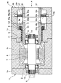
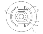
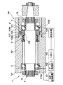
まず、本発明の第1の実施の形態を図1〜図4に基づき説明する。図1は、本発明の第1の実施の形態に係る予圧型スピンドルの構成を示す縦断面図、図2は、図1の矢印A方向から見た側面図である。図1及び図2において、上述した従来例の図19と同一部分には、同一符号が付してある。図1及び図2において図19と異なる部分は、図19の構成に振動防止手段15を付加したことである。
【0014】
振動防止手段15は、ハウジング1の後側部材1cの後端部に接続固定した円筒状の振動防止部本体16と、方形状の固定用ブロック17と、複数枚(本実施の形態では2枚)の押圧側薄板18a,18bと、複数枚(本実施の形態では2枚)の受け側薄板19a,19bと、複数個(本実施の形態では2個)の押圧バネ20a,20bと、複数個(本実施の形態では2個)の押圧子20c,20dとから構成されている。
【0015】
振動防止部本体16は、ハウジング1の後側部材1cの一端部(図1において右端部)に固定されて、ハウジング1と一体化されている。
【0016】
固定用ブロック17は、振動防止部本体16の中央部の取り付け孔内に嵌合されて、複数本のボルト21により振動防止部本体16に固定されている。
【0017】
押圧側薄板18a,18bは曲げ剛性の低いバネ性を有する薄い(例えば、板厚0.3mm)金属板からなり、ハウジング1の周方向に互いに180度偏位して互いに対向して配設されている。押圧側薄板18a,18bの各一端部(図1において左端部)は、スリーブ3の一端部(図1において右端部)に設けた取付面にボルト22a,22bによりそれぞれ固定されている。また、押圧側薄板18a,18bの各他端部(図1において右端部)は、固定用ブロック17の図において左端部の受け面にスラスト方向に移動可能に重合されている。
【0018】
受け側薄板19a,19bも曲げ剛性の低いバネ性を有する薄い(例えば、板厚0.3mm)金属板からなり、押圧側薄板18a,18bと対応してハウジング1の周方向に互いに180度偏位して互いに対向して配設されている。受け側薄板19a,19bの各一端部(図1において右端部)は、振動防止部本体16と固定用ブロック17との間にボルトによりそれぞれ挟持固定されている。また、受け側薄板19a,19bの各他端部(図1において左端部)は、押圧側薄板18a,18bの他端部にスラスト方向に移動可能に重合されている。
【0019】
押圧バネ20a,20bはコイルバネよりなるもので、振動防止部本体16の内周面と受け側薄板19a,19bの各他端部との間に介装されている。押圧子20c,20dは、ハウジング1の径方向に所定範囲移動可能に配設されている。押圧子20c,20dの一端部(図1においてハウジング1の外周側に位置する端部)側は、振動防止部本体16に穿設されたガイド孔16a内に嵌挿され、他端部(図1においてハウジング1の中心側に位置する端部)側は、受け側薄板19a,19bに接触している。押圧バネ20a,20bは押圧子20c,20dの外周部に嵌合されている。
【0020】
そして、これら押圧バネ20a,20bのバネ力により、押圧子20c,20dの他端部が受け側薄板19a,19bを介して押圧側薄板18a,18bを固定用ブロック17側に押し付けていることにより、押圧側薄板18a,18bと固定用ブロック17との間及び押圧側薄板18a,18bと受け側薄板19a,19bとの間に接触面圧(摩擦力)がそれぞれ生じるようになっている。
【0021】
このような状態で、シャフト5やスリーブ3のスラスト方向に振動力が作用すると、押圧側薄板18a,18bと固定用ブロック17との間及び押圧側薄板18a,18bと受け側薄板19a,19bとの間にそれぞれ生じる摩擦力により、前記スラスト方向の振動力が抑制され、シャフト5やスリーブ3のスラスト方向の振動が減衰される。
【0022】
このとき、押圧側薄板18a,18bは、スラスト方向にのみスリーブ3を拘束し、ハウジング1や固定用ブロック17と、押圧側薄板18a,18bとのアライメントが悪くても、押圧側薄板18a,18bの曲げ剛性が低いため、ラジアル方向やモーメント方向にスリーブ3を拘束することはなく、スラスト方向のみの剛性を向上させることができる。
【0023】
また、押圧側薄板18a,18bや受け側薄板19a,19bは、薄い板であるから曲げ剛性が低く、押圧バネ20a,20bによるバネ力を押圧側薄板18a,18bと受け側薄板19a,19bとの間及び押圧側薄板18a,18bと固定用ブロック17との間に十分作用させることができる。
【0024】
図3には、図1に示す本実施の形態に係る振動防止手段15を設けた予圧型スピンドルの2自由度系振動モデルを示す。なお、図3中、K2は前側軸受2のスラスト方向の剛性、K4は後側軸受4の剛性、K6は予圧バネ6の剛性、M5+7はシャフト系(シャフト5及びロータ7等)の質量、M3はスリーブ3系の質量である。また、K2,K4>K6であるが、K6と並列に摩擦ダンパのある点で図20の従来例と異なる。
【0025】
図4には、図1に示す本実施の形態に係る振動防止手段15を設けた予圧型スピンドルにおけるシャフト5の先端部(図1中、左端部)に加速度センサを取り付け、予圧型スピンドルの先端をスラスト方向に加振した際の加速度を前記加速度センサにより測定し、周波数分析器により処理した動剛性データを示す。同図中、横軸は周波数(Hz)を、縦軸はコンプライアンス(=振動(X)の振幅/振動力(F)の振幅;μm/kg)をそれぞれ示す。この図4によれば、第1次及び第2次共振周波数共に減衰がきいて、上述した従来例より動剛性が向上していることが分かる。
【0026】
以上詳述したように、本実施の形態に係る予圧型スピンドルによれば、ハウジング1とスリーブ3との間に振動防止手段15を設けたことにより、予圧型スピンドルのスラスト方向の減衰能が向上する。
【0027】
また、振動防止手段15の構成が簡単であり且つアライメントが悪くても各軸受2,4に無理な力がかかることがないので高い組立精度を必要としない。
【0028】
また、振動防止手段15は、後側軸受4と離間した位置にあるため、後側軸受4の外輪を変形させる恐れがない。
【0029】
また、比較的高周波の振動に対しても予圧型スピンドルのスラスト方向の減衰能がある。
【0030】
また、振動防止手段15は摩擦力を利用した構成であり、しかも押圧バネ20a,20b、薄板18a,18b、19a,19bを周方向に等間隔を存して設けているため、上述した振動防止手段15の構成が簡単であり且つスリーブ3やシャフト5にスラスト方向以外の偏荷重を作用させることがない。
【0031】
更に、振動防止手段15は押圧バネ20a,20bを用いて、薄板18a,18b、19a,19b、固定用ブロック17の摩擦力を利用した構成であるため、押圧バネ20a,20bの交換により振動防止特性を容易に変更することができる。
【0032】
なお、押圧側薄板18a,18b、押圧側薄板19a,19b及び押圧バネ20a,20bは、上述した周方向2箇所のみに限られるものではなく、周方向に等間隔を存して3箇所以上設けてもよい。
【0033】
また、押圧側薄板18a,18bと受け側薄板19a,19bとの間及び押圧側薄板18a,18bと固定用ブロック17との間には、適当な粘性を有する液体を塗布することにより、前記液体の粘性によりシャフト5やスリーブ3のスラスト方向の振動減衰特性をより高めることもできる。
【0034】
更に、押圧側薄板18a,18b、受け側薄板19a,19b及び固定用ブロック17の接触面に、滑り案内面に多用されるターカイト等の耐摩材を接着してもよい。
【0035】
(第2の実施の形態)
次に、本発明の第2の実施の形態を図5及び図6に基づき説明する。図5は本発明の第2の実施の形態に係る予圧型スピンドルの構成を示す縦断面図、図6は図5の矢印B方向から見た側面図である。なお、図5及び図6において、上述した従来例の図19と同一部分には、同一符号が付してある。図5及び図6において、図19と異なる点は、前側軸受及び後側軸受を各2個ずつ設けたことと、ハウジングの構成及びスリーブの構成と、図19の構成に振動防止手段23を付加したことである。
【0036】
即ち、シャフト5の前側端は2個の前側軸受2a,2bにより、後側端は2個の後側軸受4a,4bにより、それぞれ支持されている。
【0037】
また、ハウジング1′の中間部材1′bと後側部材1′cの外径は互いに同一に設定され、前側部材1′aの外径は中間部材1′bと後側部材1′cより小径に設定されている。
【0038】
また、スリーブ3′は、円筒状のスリーブ主体3′aと、一端部(図5において右端部)に鍔を有する円筒状のスリーブ副体3′bと、中央部に透孔を有する円板状の端板3′cとからなる。スリーブ主体3′a内に、その一端側(図5において右端側)からスリーブ副体3′bを嵌合し、スリーブ副体3′bの一端部(図5において右端部)に端板3′cを配置し、これらスリーブ主体3′a、スリーブ副体3′b及び端板3′cを互いに一体に固定することにより、スリーブ3′が構成されている。中間部材1′bの軸方向中央部外周面にはフランジ1′dが形成され、このフランジ1′dにはボルト挿通孔1′eが穿設されている。また、ハウジング1′の中間部材1′bと後側部材1′cの外径は互いに同一に設定され、前側部材1′aの外径は中間部材1′bと後側部材1′cより小径に設定されている。後側部材1′cと端板3′cとの間にリング部材12が配設されて、複数本のボルト24により後側部材1′cに固定されている。
【0039】
本実施の形態に係る振動防止手段23は、ハウジング1′の後側部材1′cの後端部に接続固定した端部に略半月状の開口25aを有する振動防止部本体25と、複数個(本実施の形態では2個)の方形状の薄板取付台26a,26bと、U字状の切欠部を有する方形状の固定用ブロック27と、複数枚(本実施の形態では2枚)の押圧側薄板28a,28bと、複数枚(本実施の形態では4枚)の受け側薄板29a,29b,29c,29d,29e,29fと、複数個(本実施の形態では2個)の方形状の支持台30a,30bと、複数本(本実施の形態では2本)の押圧子31a,31bと、複数個(本実施の形態では2個)の押圧バネ32a,32bと、から構成されている。なお、押圧用薄板28a,28b、受け側薄板29a,29b,29c,29dは耐摩耗性を向上させるため硬化熱処理が施されている。
【0040】
振動防止部本体25は、ハウジング1′の後側部材1′cの一端部(図5において右端部)に固定されて、ハウジング1′と一体化されている。
【0041】
薄板取付台26a,26bは、ハウジング1′の周方向に互いに180度偏位して互いに対向して端板3′cの一側面(図5において右側面)に複数本のボルト33a,33bにより固定されている。
【0042】
固定用ブロック27は、振動防止部本体25の一側面(図5において右側面)に複数本のボルト34により固定されている。固定用ブロック27のU字状の切欠部の円弧中心は、シャフト5の中心と整合している。
【0043】
押圧側薄板28a,28bは、曲げ剛性の低いバネ性を有する薄い(例えば、板厚0.3mm)金属板からなり、その一端部(図5において左端部)は薄板取付台26a,26bの互いに対向する取付面にボルト35a,35bにより固定されている。また、押圧側薄板28a,28bの他端部(図5において右端部)は、固定用ブロック27の上下の受け面に受け側薄板29a,29b,29c,29dを介してスラスト方向に移動可能に重合されている。なお、受け側薄板29c,29dを固着する代わりに受け側薄板29c,29dは省略し、ブロック27自体の受け面を硬化するようにしてもよい。
【0044】
受け側薄板29a,29bも、押圧側薄板28a,28bと同様に曲げ剛性の低いバネ性を有する薄い(例えば、板厚0.3mm)金属板からなり、その一端部(図6において右端部)は固定用ブロック27の上下の取付面に受け側薄板29c,29d,29e,29fを介し、ボルト36a,36bにより固定されている。なお、29e,29fは、押圧用薄板28a,28bと同じ厚さを有し、29a,29bを28a,28bの厚さの分だけ浮かせるスペーサとしての役割を果たすものである。また、受け側薄板29a,29bの他端部(図6において左端部)は、押圧側薄板28a,28bの他端部にスラスト方向に移動可能に重合されている。
【0045】
支持台30a,30bは、ガイド孔37a,37bをそれぞれ有しており、固定用ブロック27より外周側に位置して振動防止部本体25の一側面(図5において右側面)に複数本のボルト38a,38bにより固定されている。支持台30a,30bのガイド孔37a,37bは、固定用ブロック27を介して互いに対向している。
【0046】
押圧子31a,31bは、支持台30a,30bのガイド孔37a,37b内に、その軸方向に所定範囲移動可能に嵌合されている。押圧子31a,31bの一端部(固定用ブロック27側端部)は受け側薄板29a,29bの他端部に当接している。
【0047】
押圧バネ32a,32bは、押圧子31a,31bの一端部と支持台30a,30bとの間に位置して押圧子31a,31bに嵌装されている。押圧子31a,31bは、押圧バネ32a,32bのバネ力により固定用ブロック27側に向かって付勢されている。
【0048】
そして、押圧側薄板28a,28bは、押圧バネ32a,32bにより固定用ブロック27側に押し付けられていることにより、押圧側薄板28a,28bと固定用ブロック27と受け側薄板29a,29bとの間に接触面圧(摩擦力)が生じるようになっている。
【0049】
このような状態で、シャフト5やスリーブ3′のスラスト方向に振動力が作用すると、押圧側薄板28a,28bと固定用ブロック27との間及び押圧側薄板28a,28bと受け側薄板29a,29bとの間に生じる摩擦力により、前記スラスト方向の振動力が抑制され、シャフト5やスリーブ3′のスラスト方向の振動が減衰される。
【0050】
本実施の形態に係る振動防止手段23を設けた予圧型スピンドルの2自由度系振動モデル及びそのときの動剛性データは、上述した第1の実施の形態における図3及び図4と同様であり、上述した従来例より動剛性が向上している。
【0051】
また、本実施の形態に係る予圧型スピンドルによれば、上述した第1の実施の形態と同様の効果を奏する。
【0052】
なお、押圧側薄板28a,28b、押圧側薄板29a,29b、押圧子31a,31b及び押圧バネ32a,32bは、上述した周方向2箇所のみに限られるものではなく、周方向に等間隔を存して3箇所以上設けてもよい。
【0053】
また、押圧側薄板28a,28bと受け側薄板29a,29bとの間及び押圧側薄板28a,28bと固定用ブロック27との間には、適当な粘性を有する液体を塗布することにより、前記液体の粘性によりシャフト5やスリーブ3′のスラスト方向の振動減衰特性をより高めることもできる。
【0054】
更に、押圧側薄板28a,28b及び受け側薄板29a,29b及び固定用ブロック27の接触面に、滑り案内面に多用されるターカイト等の耐摩材を接着してもよい。
【0055】
(第3の実施の形態)
次に、本発明の第3の実施の形態を図7及び図8に基づき説明する。図7は本発明の第3の実施の形態に係る予圧型スピンドルの構成を示す縦断面図、図8は図7の矢印C方向から見た側面図である。なお、図7及び図8において、上述した従来例の図19と同一部分には同一符号が付してある。
【0056】
図7及び図8において、図19と異なる点は、図19の構成に振動防止手段39を付加したことである。この振動防止手段39は、複数枚(本実施の形態では2枚)の板バネ40a,40bと、これら板バネ40a,40bをハウジング1に取り付けるための複数個(本実施の形態では2個)の取付台41a,41bとからなる。取付台41a,41bは、ハウジング1の後側部材1cの一側面(図7において右側面)に、互いに周方向に180度偏位してボルト42a,42bにより固定されている。これらの取付台41a,41bに板バネ40a,40bの一端部がボルト43a,43bにより固定され、板バネ40a,40bの他端部は、弓状に撓んだ状態でスリーブ3の一端部(図7において右端部)外周面に当接し、これにより板バネ40a,40bの他端部は、スリーブ3の一端部外周面に押し付けられ、板バネ40a,40bの他端部とスリーブ3の一端部外周面との間に接触面圧(摩擦力)が生じるようになっている。
【0057】
このような状態で、シャフト5やスリーブ3のスラスト方向に振動力が作用すると、板バネ40a,40bの他端部とスリーブ3の一端部外周面との間に生じる摩擦力により、前記スラスト方向の振動力が抑制され、シャフト5やスリーブ3のスラスト方向の振動が減衰される。
【0058】
本実施の形態に係る振動防止手段39を設けた予圧型スピンドルの2自由度系振動モデル及びそのときの動剛性データは、上述した第1の実施の形態における図3及び図4と同様であり、上述した従来例より動剛性が向上している。
【0059】
また、本実施の形態に係る予圧型スピンドルは、上述した第1の実施の形態に係る予圧型スピンドルと同様の効果を奏する。
【0060】
なお、板バネ40a,40b及び取付台41a,41bは、上述した周方向2箇所のみに限られるものではなく、周方向に等間隔を存して3箇所以上設けてもよい。
【0061】
また、板バネ40a,40bの他端部とスリーブ3の一端部外周面との間には、適当な粘性を有する液体を塗布することにより、前記液体の粘性によりシャフト5やスリーブ3のスラスト方向の振動減衰特性をより高めることもできる。
【0062】
更に、板バネ40a,40bとスリーブ3の接触面に、滑り案内面に多用されるターカイト等の耐摩材を接着してもよい。
【0063】
(第4の実施の形態)
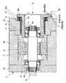
次に、本発明の第4の実施の形態を図9及び図10に基づき説明する。図9は、本発明の第4の実施の形態に係る予圧型スピンドルの構成を示す縦断面図であり、同図において上述した従来例の図19と同一部分には、同一符号が付してある。
【0064】
図9において図19と異なる部分は、図19の構成に振動防止手段44を付加したことである。この振動防止手段44は、ハウジング1の後側部材1cの後端部に接続固定した円筒状の振動防止部本体45と、複数枚(本実施の形態では2枚)の薄板46a,46bとから構成されている。
【0065】
振動防止部本体45は、ハウジング1の後側部材1cの一端部(図9において右端部)に固定されて、ハウジング1と一体化されている。
【0066】
薄板46a,46bは、曲げ剛性の低いバネ性を有する薄い(例えば、板厚0.3mm)金属板からなり、その一端部(図9において左端部)はスリーブ3の一端部(図において右端部)に互いに180度偏位して設けられた取付面にボルト47a,47bにより固定されている。薄板46a,46bの他端部(図9において右端部)は、振動防止部本体45に形成されたスリット48a,48b内にアライメント誤差に比べて十分大きな微小隙間(例えば、0.1mm〜0.3mm)を存して遊嵌されている。薄板46a,46bの他端部とスリット48a,48bとの間の隙間には、高粘度部材(例えば、グリース)49a,49bが充填されており、この高粘度部材49a,49bにより粘性ダンパ作用が生じるようになっている。
【0067】
このような状態で、シャフト5やスリーブ3のスラスト方向に振動力が作用すると、高粘度部材49a,49bの粘性ダンパ作用により、前記スラスト方向の振動力が抑制され、シャフト5やスリーブ3のスラスト方向の振動が減衰される。
【0068】
図10には、図9に示す本実施の形態に係る振動防止手段44を設けた予圧型スピンドルの2自由度系振動モデルを示す。なお、図10中、K2は前側軸受2のスラスト方向の剛性、K4は後側軸受4の剛性、K6は予圧バネ6の剛性、M5+7はシャフト系(シャフト5及びロータ7等)の質量、M3はスリーブ系の質量である。また、K2,K4>K6であるが、K6と並列に粘性ダンパがあることが図20の従来例と異なる。
【0069】
図9に示す2自由度系振動モデルのときの動剛性データは、上述した第1の実施の形態における図4と同様であり、上述した従来例より動剛性が向上している。
【0070】
また、本実施の形態に係る予圧スピンドルは、振動防止手段44の構成が簡単で且つアライメントが悪くても各軸受2,4に無理な力がかかることがないので、高い組立精度を必要としない。
【0071】
また、振動防止手段44は後側軸受4と離間した位置に設けてあるため、後側軸受4の外輪を変形させる恐れがない。
【0072】
また、比較的高周波の振動にも減衰能がある。
【0073】
更に、薄板46a,46bを周方向に等間隔に設けているため、上述した振動防止手段44の構成が簡単で且つスリーブ3やシャフト5にスラスト方向以外の偏荷重を作用させることがない。
【0074】
なお、スリット48a,48bのスリーブ3側の開口面をシール部材によりシールすることにより、高粘度部材49a,49bがスリット48a,48bから漏出しないようにしてもよい。
【0075】
また、薄板46a,46bは、上述した周方向2箇所のみに限られるものではなく、周方向に等間隔を存して3箇所以上設けてもよい。
【0076】
(第5の実施の形態)
次に、本発明の第5の実施の形態を図11に基づき説明する。図11は、本発明の第5の実施の形態に係る予圧型スピンドルの構成を示す縦断面図であり、同図において上述した従来例の図19と同一部分には、同一符号が付してある。図11において図19と異なる部分は、図19の構成に振動防止手段49を付加したことである。この振動防止手段49は、ハウジング1の後側部材1cの一端部(図11において右端部)内周面とスリーブ3の一端部(図11において右端部)外周面との間にアライメント誤差に比べて十分大きな微小隙間(例えば、0.1mm〜0.3mm)を設け、この隙間に高粘度部材(例えば、グリース)50を充填して構成されている。この高粘度部材50により粘性ダンパ作用が生じるようになっている。
【0077】
このような状態で、シャフト5やスリーブ3のスラスト方向に振動力が作用すると、高粘度部材50の粘性ダンパ作用により、前記スラスト方向の振動力が抑制され、シャフト5やスリーブ3のスラスト方向の振動が減衰される。
【0078】
本実施の形態に係る振動防止手段49を設けた予圧型スピンドルの2自由度系振動モデル及びそのときの動剛性データは、上述した第4の実施の形態における図10及び第1の実施の形態における図4と同様であり、上述した従来例より動剛性が向上している。
【0079】
また、本実施の形態に係る予圧スピンドルは、振動防止手段49の構成が簡単で且つアライメントが悪くても各軸受2,4に無理な力がかかることがないので、高い組立精度を必要としない。
【0080】
また、振動防止手段49は後側軸受4と離間した位置に設けてあるため、後側軸受4の外輪を変形させる恐れがない。
【0081】
更に、比較的高周波の振動にも減衰能がある。
【0082】
なお、高粘度部材50を充填する隙間の両側部分をOリング等のシール部材によりシールして、高粘度部材50が前記隙間から漏出しないようにしてもよい。
(第6の実施の形態)
次に、本発明の第6の実施の形態を図12に基づき説明する。図12は、本発明の第6の実施の形態に係る予圧型スピンドルの構成を示す縦断面図であり、同図において上述した従来例の図19と同一部分には、同一符号が付してある。図12において図19と異なる部分は、図19の構成に振動防止手段51を付加したことである。この振動防止手段51は、ハウジング1の後側部材1cの内端面とリング部材12との間に環状部材52を配設し、この環状部材52を後側部材1cの内端面に複数本のボルト53により固定し、この環状部材52の内周面とスリーブ3の外周面との間にアライメント誤差に比べて十分大きな微小隙間(例えば、0.1mm〜0.3mm)を設け、この隙間に高粘度部材(例えば、グリース)54を充填して構成されている。この高粘度部材54により粘性ダンパ作用が生じるようになっている。
【0083】
このような状態で、シャフト5やスリーブ3のスラスト方向に振動力が作用すると、高粘度部材54の粘性ダンパ作用により、前記スラスト方向の振動力が抑制され、シャフト5やスリーブ3のスラスト方向の振動が減衰される。
【0084】
本実施の形態に係る振動防止手段51を設けた予圧型スピンドルの2自由度系振動モデル及びそのときの動剛性データは、上述した第4の実施の形態における図10及び第1の実施の形態における図4と同様であり、上述した従来例より動剛性が向上している。
【0085】
また、本実施の形態に係る振動防止手段51は、上述した第6の実施の形態に係る振動防止手段と同様の効果を奏する。
【0086】
(第7の実施の形態)
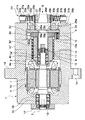
次に、本発明の第7の実施の形態を図13及び図14に基づき説明する。図13は、本発明の第7の実施の形態に係る予圧型スピンドルの構成を示す縦断面図であり、同図において上述した従来例の図19と同一部分には、同一符号が付してある。本実施の形態に係る予圧型スピンドルは、定圧予圧形式から定位置予圧形式及びその逆に切り換えできるようにしたものである。
【0087】
図13において図19と異なる部分は、図19の構成に振動防止手段55を付加したことである。この振動防止手段55は、ハウジング1の後側部材1cの後端部に接続固定した円筒状の振動防止部本体56と、方形状の固定用ブロック57と、複数枚(本実施の形態では2枚)の押圧側薄板58a,58bと、複数枚(本実施の形態では2枚)の受け側薄板59a,59bと、複数個(本実施の形態では2個)のアクチュエータである油圧シリンダ60a,60bとから構成されている。
【0088】
振動防止部本体56は、ハウジング1の後側部材1cの一端部(図1において右端部)に固定されて、ハウジング1と一体化されている。
【0089】
固定用ブロック57は、振動防止部本体56の中央部の取り付け孔内に嵌合されて、複数本のボルト61により振動防止部本体56に固定されている。
【0090】
押圧側薄板58a,58bは曲げ剛性の低いバネ性を有する薄い(例えば、板厚0.3mm)金属板からなり、ハウジング1の周方向に互いに180度偏位して互いに対向して配設されている。押圧側薄板58a,58bの各一端部(図1において左端部)は、スリーブ3の一端部(図1において右端部)に設けた取付面にボルト62a,62bによりそれぞれ固定されている。また、押圧側薄板58a,58bの各他端部(図1において右端部)は、固定用ブロック57の図において左端部の受け面にスラスト方向に移動可能に重合されている。
【0091】
受け側薄板59a,59bも曲げ剛性の低いバネ性を有する薄い(例えば、板厚0.3mm)金属板からなり、押圧側薄板58a,58bと対応してハウジング1の周方向に互いに180度偏位して互いに対向して配設されている。受け側薄板59a,59bの各一端部(図1において右端部)は、振動防止部本体56と固定用ブロック57との間にボルトによりそれぞれ挟持固定されている。また、受け側薄板59a,59bの各他端部(図1において左端部)は、押圧側薄板58a,58bの他端部にスラスト方向に移動可能に重合されている。
【0092】
油圧シリンダ60a,60bは、振動防止部本体56の内周面と受け側薄板59a,59bの各他端部との間に配設されている。油圧シリンダ60a,60bの各シリンダ本体63a,63bの一端部は、振動防止部本体56の内周面に固定され、油圧シリンダ60a,60bの各ピストンロッド64a,64bの各先端部は、受け側薄板59a,59bの各他端部に当接している。
【0093】
そして、受け側薄板59a,59bは、予圧型スピンドルが熱的平衡状態、即ちシャフト5の熱膨脹が収束した状態に達した時点で、油圧シリンダ60a,60bの各ピストンロッド64a,64bが固定用ブロック57側に移動して、受け側薄板59a,59bを介して押圧側薄板58a,58bを固定用ブロック57に押しつけることにより、押圧側薄板58a,58bと固定用ブロック57との間及び押圧側薄板58a,58bと受け側薄板59a,59bとの間に接触面圧(摩擦力)がそれぞれ生じるようになっている。
【0094】
油圧シリンダ60a,60bの各ピストンロッド64a,64bが固定用ブロック57側に移動して、受け側薄板59a,59bを介して押圧側薄板58a,58bを固定用ブロック57に押しつけたとき、油圧シリンダ60a,60bの各ピストンロッド64a,64bは、スリーブ3やシャフト5の軸芯に対して直角方向に動作し、スリーブ3の位置がスラスト方向にずれないものとする。
【0095】
更に、油圧シリンダ60a,60bの各ピストンロッド64a,64bは、受け側薄板59a,59bを介して押圧側薄板58a,58bを固定用ブロック57に押しつけるため、押圧側薄板58a,58bにはスラスト方向の力はほとんどかからない。
【0096】
予圧型スピンドルの熱的平衡状態、即ちシャフト5の熱膨張が収束した状態は、熱的平衡状態検出手段である変位センサー66により検出できるようになっている。この変位センサー66は、振動防止部本体56の内周面所定箇所に固定されたブラケット66aの先端部に取り付けられて、シャフト5の後端部(図13において右端部)と対向している。変位センサー66の軸線はシャフト5の軸線と整合されていて、シャフト5の熱影響による変位を検出するものである。変位センサー66の出力側は増幅器67に接続され、この増幅器67の出力側はデータ処理部68に接続され、このデータ処理部68の出力側はコントローラ69に接続され、このコントローラ69の出力側は油圧シリンダ60a,60bに接続されている。そして、変位センサー66がシャフト5の後端部の熱影響による変位を検出すると、その検出信号が増幅器67を介してデータ処理部68に入力され、データ処理部68では逐次入力される信号を監視していて、予め用意されたプログラムに基づき、一定時間内での変位の値の変動幅が所定の値以下となることが検知されると、コントローラ69に対し信号を出力する。コントローラ69は、この信号を受信すると、押圧シリンダ60a,60bの制御を開始する。即ち、コントローラ69からの制御信号により油圧シリンダ60a,60bが制御されるようになっている。
【0097】
予圧型スピンドルが熱的平衡状態に達した時点で、シャフト5やスリーブ3のスラスト方向に振動力が作用すると、油圧シリンダ60a,60bの各ピストンロッド64a,64bが、受け側薄板59a,59bを介して押圧側薄板58a,58bを固定用ブロック57に押しつけることにより、押圧側薄板58a,58bと固定用ブロック57との間及び押圧側薄板58a,58bと受け側薄板59a,59bとの間にそれぞれ生じる摩擦力により、前記スラスト方向の振動力が抑制され、シャフト5やスリーブ3のスラスト方向の振動が減衰される。
【0098】
このとき、押圧側薄板58a,58bは、スラスト方向にのみスリーブ3を拘束し、ハウジング1やブロック57と、押圧側薄板58a,58bとのアライメントが悪くても、押圧側薄板58a,58bの曲げ剛性が低いため、ラジアル方向やモーメント方向にスリーブ3を拘束することはなく、スラスト方向のみの静・動剛性を向上させることができる。
【0099】
即ち、本実施の形態に係る予圧型スピンドルによれば、予圧型スピンドルが熱的平衡状態、即ちシャフト5の熱膨張が収束した状態で油圧シリンダ60a,60bの各ピストンロッド64a,64bを作動させて、受け側薄板59a,59bを介して押圧側薄板58a,58bを固定用ブロック57に押しつけクランプすることにより、図20に示す2自由度系が図14に示すように1自由度系となり、予圧型スピンドルのスラスト方向の静・動剛性が向上する。
【0100】
そして、予圧型スピンドルの使用が終了したら、前記クランプを解除した後、その回転を停止させる。このように、予圧型スピンドルの使用中のみ、後側軸受4の位置をシャフト5の熱膨張分変位させた状態でクランプすることにより、即ち定圧予圧型式から定位置予圧型式に切り換えることで、予圧型スピンドルのスラスト方向の静・動剛性が向上する。
【0101】
図14には、図13に示す本実施の形態に係る振動防止手段55を設けた予圧型スピンドルの1自由度系振動モデルを示す。なお、図13中、K2は前側軸受2のスラスト方向の剛性、K4は後側軸受4の剛性、M5+7はシャフト系(シャフト5及びロータ7等)の質量である。
【0102】
実用上は、予め予圧型スピンドルが熱的平衡状態に到達するまでの時間を上記のような方法で計測しておき、実際のスピンドルの使用時には、変位センサーは用いず、予め計測した時間をセットしたタイマーによりクランプ用のアクチュエータである油圧シリンダ60a,60bを作動させることもできる。
【0103】
また、後述の実施の形態のように、変位センサーに代え、温度センサーを用いるようにしてもよい。
【0104】
本実施の形態に係る予圧型スピンドルによれば、シャフト5の熱膨張により軸受予圧が大きく変動してしまうという定位置予圧形式の短所及び予圧型スピンドルのスラスト方向の静・動剛性が低く、この方向の振動が生じやすいという定圧予圧形式の短所を同時に解消することができる。
【0105】
なお、押圧側薄板58a,58b、受け側薄板59a,59b及び油圧シリンダ60a,60bは、上述した周方向2箇所のみに限られるものではなく、周方向に等間隔を存して3箇所以上設けてもよい。
【0106】
また、押圧側薄板58a,58b、受け側薄板59a,59b及びブロック57の接触面に、滑り案内面に多用されるターカイト等の耐摩材を接着してもよい。
【0107】
(第8の実施の形態)
次に、本発明の第8の実施の形態を図15に基づき説明する。図15は本発明の第8の実施の形態に係る予圧型スピンドルの構成を示す縦断面図である。なお、図15において、上述した従来例の図19と同一部分には、同一符号が付してある。図15において図19と異なる点は、図19の構成に振動防止手段70、温度記録装置71、データ処理部72、コントローラ73及び油圧系統74を付加したことである。
【0108】
本実施の形態に係る振動防止手段70は、ハウジング1の後側部材1cの後端部に接続固定した円筒状の振動防止部本体75を有している。振動防止部本体75は、ハウジング1の後側部材1cの一端部(図15において右端部)に固定されて、ハウジング1と一体化されている。振動防止部本体75は、外周側部材75aと内周側部材75bとからなる2重構造である。外周側部材75aと内周側部材75bとの間には環状溝76が形成され、この環状溝76内には、油77が充填されている。外周側部材75aと内周側部材75bとの接合面には、環状溝76の両側に位置してシールリング78a,78bが設けられており、これらのシールリング78a,78bにより、環状溝76内の油77が外周側部材75aと内周側部材75bとの接合面から外方へ漏出しないようになっている。内周側部材75bの環状溝76の底部は、その中央部が厚肉部79aとされ且つその両側が薄肉部79bとされている。この厚肉部79aは、スリーブ3の一端部(図15において右端部)のフランジ3aの外周面に重合している。そして、環状溝76内の油77の圧力を高めることにより、薄肉部79bが中心側に向かって変形し、これに伴って厚肉部79aも中心側に変位してフランジ3aの外周面に密着してフランジ3aをクランプするようになっている。
【0109】
温度記録装置71は、前側軸受2及び後側軸受4の温度、即ち予圧型スピンドルの熱的平衡状態(シャフト5の熱膨張が収束した状態)を検出する温度センサー80a,80bに接続され、温度センサー80a,80bの検出した温度データを記録するようになっている。データ処理部72は温度記録装置71の出力側に接続されている。データ処理部72の出力側はコントローラ73に接続され、このコントローラ73の出力側は油圧系統74に接続され、この油圧系統74は環状溝76内の油77に接続されている。
【0110】
そして、温度センサー80a,80bの検出した温度データは、データ処理部72で一定時間内での温度の値の変動幅が所定の値以下となると、前記第7の実施の形態の場合と同様、信号がコントローラ73に送られ、このコントローラ73からの制御信号により油圧系統74が制御されて、環状溝76内の油77に対して圧力をかけたり、その圧力を解除し得るようになっている。
【0111】
予圧型スピンドルが熱的平衡状態に達した時点で、環状溝76内の油77に対して圧力がかかり、薄肉部79bが中心側に向かって変形し、これに伴って厚肉部79aも中心側に変位してフランジ3aの外周面に密着してフランジ3aをクランプする。これにより、スピンドルのスラスト方向の振動力が抑制され、シャフト5やスリーブ3のスラスト方向の振動が減衰される。
【0112】
本実施の形態に係る予圧型スピンドルの1軸系振動モデルは、上述した第7の実施の形態における図14と同様であり、上述した従来例より静剛性及び動剛性が向上している。
【0113】
実用上は、予め予圧型スピンドルが熱的平衡状態に到達するまでの時間を上記のような方法で計測しておき、実際のスピンドルの使用時には、温度センサーは用いず、予め計測した時間をセットしたタイマーによりクランプ用のアクチュエータである押圧系統74を作動させることもできる。
【0114】
また、熱平衡状態(熱膨張が収束した状態)を検知するのに温度センサーを用いたが、代わりに第7の実施の形態と同様に変位センサーを用いた構成としてもよい。
【0115】
また、本実施の形態に係る予圧型スピンドルは、上述した第7の実施の形態に係る予圧型スピンドルと同様の効果を奏する。
【0116】
(第9の実施の形態)
次に、本発明の第9の実施の形態を図16に基づき説明する。図16は本発明の第9の実施の形態に係る予圧型スピンドルの構成を示す縦断面図である。なお、図16において、上述した従来例の図19と同一部分には、同一符号が付してある。図16において図19と異なる点は、図19の構成に振動防止手段81、温度記録装置82、データ処理部83、コントローラ84及び油圧系統85を付加したことである。
【0117】
本実施の形態に係る振動防止手段81は、ハウジング1の後側部材1cの後端部に接続固定した円筒状の振動防止部本体86を有している。振動防止部本体86は、ハウジング1の後側部材1cの一端部(図16において右端部)に固定されて、ハウジング1と一体化されている。振動防止部本体86は、外周側部材86aと内周側部材86bとからなる2重構造である。外周側部材86aと内周側部材86bとの間には環状溝87が形成され、この環状溝87内には、油88が充填されている。外周側部材86aと内周側部材86bとの接合面には、環状溝87の両側に位置してシールリング89a,89bが設けられており、これらのシールリング89a,89bにより、環状溝87内の油88が外周側部材86aと内周側部材86bとの接合面から外方へ漏出しないようになっている。内周側部材86bの環状溝87の底部は、その中央部が薄肉部90aとされ且つその両側が厚肉部90bとされている。内周側部材86bの内周面はスリーブ3の外周面に摺接している。そして、環状溝87内の油88の圧力を高めることにより、薄肉部90aが中心側に向かって変形し、スリーブ3の外周面に密着して該スリーブ3をクランプするようになっている。
【0118】
温度記録装置82は、前側軸受2及び後側軸受4の温度、即ち予圧型スピンドルの熱的平衡状態(シャフト5の熱膨張が収束した状態)を検出する温度センサー91a,91bに接続され、温度センサー91a,91bの検出した温度データを記録するようになっている。データ処理部83は温度記録装置82の出力側に接続されている。データ処理部83の出力側はコントローラ84に接続され、このコントローラ84の出力側は油圧系統85に接続され、この油圧系統85は環状溝87内の油88に接続されている。
【0119】
そして、温度センサー91a,91bの検出した温度データは、データ処理部83で一定時間内での温度の値の変動幅が所定の値以下となると、前記第8の実施の形態の場合と同様、信号がコントローラ84に送られ、このコントローラ84からの制御信号により油圧系統85が制御されて、環状溝87内の油88に対して圧力をかけたり、その圧力を解除し得るようになっている。
【0120】
予圧型スピンドルが熱的平衡状態に達した時点で、環状溝87内の油88に対して圧力がかかり、薄肉部90aが中心側に向かって変形してスリーブ3の外周面に密着して該スリーブ3をクランプする。これにより、予圧型スピンドルのスラスト方向の振動力が抑制され、シャフト5やスリーブ3のスラスト方向の振動が減衰される。
【0121】
本実施の形態に係る予圧型スピンドルの1軸系振動モデルは、上述した第7の実施の形態における図14と同様であり、上述した従来例より静剛性及び動剛性が向上している。
【0122】
実用上は、予め予圧型スピンドルが熱的平衡状態に到達するまでの時間を上記のような方法で計測しておき、実際のスピンドルの使用時には、温度センサーは用いず、予め計測した時間をセットしたタイマーによりクランプ用のアクチュエータである油圧系統85を作動させることもできる。
【0123】
また、熱平衡状態(熱膨張が収束した状態)を検知するのに温度センサーを用いたが、代わりに第7の実施の形態と同様に変位センサーを用いた構成としてもよい。
【0124】
また、本実施の形態に係る予圧型スピンドルは、上述した第7の実施の形態に係る予圧型スピンドルと同様の効果を奏する。
【0125】
なお、本実施の形態の場合の予圧バネ6は、スリーブ3のフランジ3aと内周側部材86bの一端部(図16において右端部)との間に配設されている。
【0126】
(第10の実施の形態)
次に、本発明の第10の実施の形態を図17に基づき説明する。図17は、本発明の第10の実施の形態に係る予圧型スピンドルの構成を示す縦断面図であり、同図において上述した従来例の図19と同一部分には、同一符号が付してある。図17において図19と異なる部分は、図19の構成に振動防止手段92、温度記録装置93、データ処理部94、コントローラ95を付加したことである。
【0127】
本実施の形態に係る振動防止手段92は、ハウジング1の後側部材1cの後端部に接続固定した円筒状の振動防止部本体96と、外形把握チャック97とから構成されている。振動防止部本体96の外径はハウジング1の外径と同一に設定されている。振動防止部本体96は、ハウジング1の後側部材1cの一端部(図17において右端部)に固定されて、ハウジング1と一体化されている。振動防止部本体96は、その内部に環状の中空部98を有し、該中空部98内に外形把握チャック97が設けられている。振動防止部本体96の中空部98の底部は、その中央部が厚肉部98aとされ且つその両側が薄肉部98bとされている。この厚肉部98aは、スリーブ3の一端部(図17において右端部)のフランジ3aの外周面に重合している。そして、外形把握チャック97を作動させることにより、厚肉部98aが中心側に向かって変形し、フランジ3aの外周面に密着してフランジ3aをクランプするようになっている。
【0128】
温度記録装置93は、前側軸受2及び後側軸受4の温度、即ちスピンドルの熱的平衡状態(シャフト5の熱膨張が収束した状態)を検出する温度センサー99a,99bに接続され、温度センサー99a,99bの検出した温度データを記録するようになっている。データ処理部94は温度記録装置93の出力側に接続されている。データ処理部94の出力側はコントローラ95に接続され、このコントローラ95の出力側は外形把握チャック97に接続されている。
【0129】
そして、温度センサー99a,99bの検出した温度データは、データ処理部94で一定時間内での温度の値の変動幅が所定の値以下となると、前記第8の実施の形態の場合と同様、信号がコントローラ95に送られ、このコントローラ95からの制御信号により外形把握チャック97が作動し得るようになっている。
【0130】
予圧型スピンドルが熱的平衡状態に達した時点で、外形把握チャック97が作動し、厚肉部98aが中心側に向かって変形してフランジ3aの外周面に密着し、該フランジ3aをクランプする。これにより、予圧型スピンドルのスラスト方向の振動力が抑制され、シャフト5やスリーブ3のスラスト方向の振動が減衰される。
【0131】
本実施の形態に係る予圧型スピンドルの1軸系振動モデルは、上述した第7の実施の形態における図14と同様であり、上述した従来例より静剛性及び動剛性が向上している。
【0132】
実用上は、予め予圧型スピンドルが熱的平衡状態に到達するまでの時間を上記のような方法で計測しておき、実際のスピンドルの使用時には、温度センサーは用いず、予め計測した時間をセットしたタイマーによりクランプ用のアクチュエータである外形把握チャック97を作動させることもできる。
【0133】
また、熱平衡状態(熱膨張が収束した状態)を検知するのに温度センサーを用いたが、代わりに第7の実施の形態と同様に変位センサーを用いた構成としてもよい。
【0134】
また、本実施の形態に係る予圧型スピンドルは、上述した第7の実施の形態に係る予圧型スピンドルと同様の効果を奏する。
【0135】
(第11の実施の形態)
次に、本発明の第11の実施の形態を図18に基づき説明する。図18は、本発明の第11の実施の形態に係る予圧型スピンドルの構成を示す縦断面図であり、同図において上述した従来例の図19と同一部分には、同一符号が付してある。図18において図19と異なる部分は、後側軸受4の外輪に直接予圧をかけるようにしたタイプであること、ハウジングの構成、図19の構成に振動防止手段100、温度記録装置101、データ処理部102、コントローラ103、油圧系統104を付加したことである。
【0136】
本実施の形態に係るハウジング1゛は、前側部材1゛a、中間部材1゛b、後側部材1゛cよりなる。後側部材1゛cは中間部材1゛bの後端部外周に嵌合されている。中間部材1゛bの後端部外周面には環状溝106が形成され、この環状溝106内には、油107が充填されている。環状溝106の両側に位置して中間部材1゛bと後側部材1゛cとの間には、シールリング108a,108bが設けられ、これらシールリング108a,108bにより、環状溝106内の油107が中間部材1゛bと後側部材1゛cとの間から漏出しないようになっている。
【0137】
中間部材1゛bの内部に形成された段部にはバネ受けリング109が当接され、後側軸受4の一端部(図18において左端部)にはリング状のスリーブ3゛の一端部(図18において右端部)が当接されている。そして、バネ受けリング109とスリーブ3゛との間に予圧バネ6が介装されている。従って、予圧バネ6により後側軸受4の外輪に直接予圧がかけられている。
【0138】
本実施の形態に係る振動防止手段100は、油107を含む環状溝106を有している。環状溝106は油圧系統105に接続されている。後側部材1゛cの環状溝106の底部は薄肉部109とされ、この薄肉部109はスリーブ3゛の外周面に当接している。そして、環状溝106内の油107に圧力をかけることにより、薄肉部109が中心側に向かって変形してスリーブ3゛の外周面に密着し、該スリーブ3゛をクランプするようになっている。
【0139】
温度記録装置101は、前側軸受2及び後側軸受4の温度、即ちスピンドルの熱的平衡状態(シャフト5の熱膨張が収束した状態)を検出する温度センサー110a,110bに接続され、温度センサー110a,110bの検出した温度データを記録するようになっている。データ処理部102は温度記録装置101の出力側に接続されている。データ処理部102の出力側はコントローラ103に接続され、このコントローラ103の出力側は油圧系統104に接続されている。
【0140】
そして、温度センサー110a,110bの検出した温度データは、データ処理部102で一定時間内での変位の値の変動幅が所定の値以下となると、前記第8の実施の形態の場合と同様、信号がコントローラ103に送られ、このコントローラ103からの制御信号により油圧系統104を介して環状溝106内の油107に圧力がかかるようになっている。
【0141】
予圧型スピンドルが熱的平衡状態に達した時点で、環状溝106内の油107に圧力がかかり、薄肉部109が中心側に向かって変形してスリーブ3゛の外周面に密着し、該スリーブ3゛をクランプする。これにより、予圧型スピンドルのスラスト方向の振動力が抑制され、シャフト5やスリーブ3のスラスト方向の振動が減衰される。
【0142】
本実施の形態に係る予圧型スピンドルの1軸系振動モデルは、上述した第7の実施の形態における図14と同様であり、上述した従来例より静剛性及び動剛性が向上している。
【0143】
実用上は、予め予圧型スピンドルが熱的平衡状態に到達するまでの時間を上記のような方法で計測しておき、実際のスピンドルの使用時には、温度センサーは用いず、予め計測した時間をセットしたタイマーによりクランプ用のアクチュエータである油圧系統104を作動させることができる。
【0144】
また、熱平衡状態(熱膨張が収束した状態)を検知するのに温度センサーを用いたが、代わりに第7の実施の形態と同様に変位センサーを用いた構成としてもよい。
【0145】
また、本実施の形態に係る予圧型スピンドルは、上述した第7の実施の形態に係る予圧型スピンドルと同様の効果を奏する。
【0146】
【発明の効果】
以上詳述したように本発明の予圧型スピンドルによれば、スリーブの静的な軸方向変位を許容しつつ動剛性を向上させ、予圧型スピンドルのスラスト方向の振動を効果的に減衰させることができるという効果を奏する。
【図面の簡単な説明】
【図1】本発明の第1の実施の形態に係る予圧型スピンドルの構成を示す縦断面図である。
【図2】図1の矢印A方向から見た側面図である。
【図3】図1に示す予圧型スピンドルの2自由度系振動モデルを示す図である。
【図4】図1に示す予圧型スピンドルの図3に示す2自由度系振動モデルにおけるスラスト方向の動剛性を示す図である。
【図5】本発明の第2の実施の形態に係る予圧型スピンドルの構成を示す縦断面図である。
【図6】図1の矢印B方向から見た側面図である。
【図7】本発明の第3の実施の形態に係る予圧型スピンドルの構成を示す縦断面図である。
【図8】図1の矢印C方向から見た側面図である。
【図9】本発明の第4の実施の形態に係る予圧型スピンドルの構成を示す縦断面図である。
【図10】図9に示す予圧型スピンドルの2自由度系振動モデルを示す図である。
【図11】本発明の第5の実施の形態に係る予圧型スピンドルの構成を示す縦断面図である。
【図12】本発明の第6の実施の形態に係る予圧型スピンドルの構成を示す縦断面図である。
【図13】本発明の第7の実施の形態に係る予圧型スピンドルの構成を示す縦断面図である。
【図14】図13に示す予圧型スピンドルの1自由度系振動モデルを示す図である。
【図15】本発明の第8の実施の形態に係る予圧型スピンドルの構成を示す縦断面図である。
【図16】本発明の第9の実施の形態に係る予圧型スピンドルの構成を示す縦断面図である。
【図17】本発明の第10の実施の形態に係る予圧型スピンドルの構成を示す縦断面図である。
【図18】本発明の第11の実施の形態に係る予圧型スピンドルの構成を示す縦断面図である。
【図19】従来の予圧型スピンドルの構成を示す縦断面図である。
【図20】図19に示す従来の予圧型スピンドルの2自由度系振動モデルを示す図である。
【図21】図19に示す従来の予圧型スピンドルの図20に示す2自由度系振動モデルにおけるスラスト方向の動剛性を示す図である。
【符号の説明】
1 ハウジング
1′ ハウジング
1゛ ハウジング
2 前側軸受
3 スリーブ
3′ スリーブ
3゛ スリーブ
4 後側軸受
5 シャフト
6 予圧バネ
5 振動防止手段
23 振動防止手段
39 振動防止手段
44 振動防止手段
49 振動防止手段
51 振動防止手段
55 振動防止手段
70 振動防止手段
81 振動防止手段
92 振動防止手段
100振動防止手段[0001]
BACKGROUND OF THE INVENTION
The present invention is a preload type suitable as a rotary shaft that requires quiet rotation, such as a rotary shaft of a machine tool such as an internal grinding machine, a rotary shaft of a VTR head drum, a magnetic disk of a computer, or a rotary shaft of a magnetic drum. Concerning the spindle.
[0002]
[Prior art]
FIG. 19 is a longitudinal sectional view of a conventional preload spindle of this type. In the figure, a preload type spindle includes a
[0003]
In this conventional preload type spindle, the compression force of the
[0004]
Therefore, as one measure for solving such a problem, as shown in FIG. 19 described above, a mechanism that has no rattling and has a smooth movement is formed by rolling contact between the
[0005]
Further, a preload type spindle in which the outer ring of the
[0006]
[Problems to be solved by the invention]
However, the preload type spindle in which the
[0007]
Further, in this kind of preload type spindle, the static rigidity in the thrust direction is determined only by the front bearing 2, and the
[0008]
In FIG. 20, K2 is the rigidity of the front bearing 2 in the thrust direction, K4 is the rigidity of the
[0009]
In FIG. 21, an acceleration sensor is attached to the tip end portion (left end portion in FIG. 19) of the
[0010]
The present invention has been made in view of the above-described problems of the prior art, and an object of the present invention is to provide a preload type spindle that can prevent vibration in the thrust direction. It is.
[0011]
[Means for Solving the Problems]
To achieve the above object, a preload spindle according to the present invention is provided with a housing, a front bearing mounted inside the housing, and a rear inside of the housing so as to be movable within a predetermined range in the axial direction thereof. A sleeve, a rear bearing mounted in the sleeve so as to be movable integrally with the sleeve, and a shaft rotatably supported in the housing via the front bearing and the rear bearing; A preload type spindle comprising a preload spring for applying a preload in the axial direction to the rear bearing, and is provided integrally with the housing at a position spaced apart from the rear bearing of the sleeve in the axial direction. A plate material having a low bending rigidity and a spring property is disposed between the sleeve and the sleeve without restraining the sleeve in a radial direction and a moment direction, With the sleeve allowed to move in the axial direction Against axial direction due to attenuation A vibration preventing means for performing a vibration preventing action is provided.
[0012]
DETAILED DESCRIPTION OF THE INVENTION
Hereinafter, embodiments of the present invention will be described with reference to the drawings.
[0013]
(First embodiment)
First, a first embodiment of the present invention will be described with reference to FIGS. FIG. 1 is a longitudinal sectional view showing a configuration of a preload type spindle according to a first embodiment of the present invention, and FIG. 2 is a side view seen from the direction of arrow A in FIG. 1 and 2, the same parts as those in FIG. 19 of the conventional example described above are denoted by the same reference numerals. 1 and FIG. 2 is different from FIG. 19 in that
[0014]
The
[0015]
The vibration prevention unit
[0016]
The fixing
[0017]
The pressing side
[0018]
The receiving
[0019]
The
[0020]
And by the spring force of these
[0021]
In this state, when a vibration force acts in the thrust direction of the
[0022]
At this time, the pressing side
[0023]
Further, since the pressing side
[0024]
FIG. 3 shows a two-degree-of-freedom vibration model of a preload spindle provided with the vibration preventing means 15 according to the present embodiment shown in FIG. In FIG. 3, K2 is the rigidity of the
[0025]
In FIG. 4, an acceleration sensor is attached to the tip portion (left end portion in FIG. 1) of the
[0026]
As described above in detail, according to the preload type spindle according to the present embodiment, the
[0027]
Further, even if the structure of the
[0028]
Further, since the
[0029]
In addition, the preload type spindle has a damping capability in the thrust direction against relatively high frequency vibrations.
[0030]
Further, the
[0031]
Furthermore, since the vibration preventing means 15 uses the
[0032]
The pressing-side
[0033]
Further, by applying a liquid having an appropriate viscosity between the pressing side
[0034]
Further, a wear-resistant material such as turkeyite frequently used for the sliding guide surface may be bonded to the contact surfaces of the pressing side
[0035]
(Second Embodiment)
Next, a second embodiment of the present invention will be described with reference to FIGS. FIG. 5 is a longitudinal sectional view showing a configuration of a preload spindle according to the second embodiment of the present invention, and FIG. 6 is a side view seen from the direction of arrow B in FIG. 5 and 6, the same parts as those in FIG. 19 of the conventional example described above are denoted by the same reference numerals. 5 and 6 are different from FIG. 19 in that two front bearings and two rear bearings are provided, the structure of the housing and the structure of the sleeve, and the
[0036]
That is, the front end of the
[0037]
Further, the outer diameters of the intermediate member 1'b and the rear member 1'c of the housing 1 'are set to be the same, and the outer diameter of the front member 1'a is larger than that of the intermediate member 1'b and the rear member 1'c. It is set to a small diameter.
[0038]
The sleeve 3 'includes a cylindrical sleeve main body 3'a, a cylindrical sleeve sub-body 3'b having a flange at one end (right end in FIG. 5), and a disc having a through hole at the center. And an end plate 3'c. The sleeve sub body 3'b is fitted into the sleeve main body 3'a from one end side (right end side in FIG. 5), and the
[0039]
The vibration preventing means 23 according to the present embodiment includes a vibration preventing portion
[0040]
The vibration preventing
[0041]
The thin plate mounts 26a and 26b are offset by 180 degrees in the circumferential direction of the housing 1 'and face each other by a plurality of
[0042]
The fixing
[0043]
The pressing side
[0044]
Similarly to the pressing side
[0045]
The support bases 30a and 30b have
[0046]
The
[0047]
The
[0048]
The pressing side
[0049]
In this state, when a vibration force acts in the thrust direction of the
[0050]
The two-degree-of-freedom vibration model of the preload spindle provided with the vibration preventing means 23 according to the present embodiment and the dynamic stiffness data at that time are the same as those in FIGS. 3 and 4 in the first embodiment described above. The dynamic rigidity is improved as compared with the conventional example described above.
[0051]
Moreover, according to the preload type spindle concerning this Embodiment, there exists an effect similar to 1st Embodiment mentioned above.
[0052]
Note that the pressing side
[0053]
Further, by applying a liquid having an appropriate viscosity between the pressing side
[0054]
Further, a wear-resistant material such as turkeyite frequently used for the sliding guide surface may be bonded to the contact surfaces of the pressing side
[0055]
(Third embodiment)
Next, a third embodiment of the present invention will be described with reference to FIGS. FIG. 7 is a longitudinal sectional view showing the configuration of a preload type spindle according to the third embodiment of the present invention, and FIG. 8 is a side view seen from the direction of arrow C in FIG. 7 and 8, the same parts as those in the conventional example shown in FIG.
[0056]
7 and 8 are different from FIG. 19 in that
[0057]
In this state, when a vibration force acts in the thrust direction of the
[0058]
The two-degree-of-freedom vibration model of the preload spindle provided with the vibration preventing means 39 according to the present embodiment and the dynamic stiffness data at that time are the same as those in FIGS. 3 and 4 in the first embodiment described above. The dynamic rigidity is improved as compared with the conventional example described above.
[0059]
Further, the preload spindle according to the present embodiment has the same effect as the preload spindle according to the first embodiment described above.
[0060]
The
[0061]
Further, by applying a liquid having an appropriate viscosity between the other end of the
[0062]
Furthermore, an anti-wear material such as turkeyite frequently used for the sliding guide surface may be bonded to the contact surface between the
[0063]
(Fourth embodiment)
Next, a fourth embodiment of the present invention will be described with reference to FIGS. FIG. 9 is a longitudinal sectional view showing the configuration of a preload spindle according to the fourth embodiment of the present invention. In FIG. 9, the same parts as those in FIG. is there.
[0064]
9 is different from FIG. 19 in that
[0065]
The vibration preventing portion
[0066]
The
[0067]
In this state, when a vibration force acts in the thrust direction of the
[0068]
FIG. 10 shows a two-degree-of-freedom vibration model of a preload spindle provided with the vibration preventing means 44 according to the present embodiment shown in FIG. In FIG. 10, K2 is the rigidity of the
[0069]
The dynamic stiffness data for the two-degree-of-freedom vibration model shown in FIG. 9 is the same as that in FIG. 4 in the first embodiment described above, and the dynamic stiffness is improved as compared with the above-described conventional example.
[0070]
Further, the preload spindle according to the present embodiment does not require a high assembling accuracy since the
[0071]
Further, since the
[0072]
Also, it has a damping capability for relatively high frequency vibrations.
[0073]
Further, since the
[0074]
The high viscosity members 49a and 49b may be prevented from leaking from the
[0075]
Moreover, the
[0076]
(Fifth embodiment)
Next, a fifth embodiment of the present invention will be described with reference to FIG. FIG. 11 is a longitudinal sectional view showing the structure of a preload type spindle according to the fifth embodiment of the present invention. In FIG. 11, the same parts as those in FIG. is there. 11 differs from FIG. 19 in that
[0077]
In this state, when a vibration force acts in the thrust direction of the
[0078]
The two-degree-of-freedom vibration model of the preload type spindle provided with the vibration preventing means 49 according to the present embodiment and the dynamic stiffness data at that time are shown in FIG. 10 and the first embodiment in the fourth embodiment described above. In FIG. 4, the dynamic rigidity is improved as compared with the conventional example described above.
[0079]
In addition, the preload spindle according to the present embodiment does not require a high assembly accuracy because the
[0080]
Further, since the
[0081]
Furthermore, it has a damping ability for relatively high frequency vibrations.
[0082]
In addition, the both sides of the gap filling the
(Sixth embodiment)
Next, a sixth embodiment of the present invention will be described with reference to FIG. FIG. 12 is a longitudinal sectional view showing a configuration of a preload spindle according to the sixth embodiment of the present invention. In FIG. 12, the same parts as those in FIG. is there. 12 differs from FIG. 19 in that
[0083]
In this state, when a vibration force acts in the thrust direction of the
[0084]
The two-degree-of-freedom vibration model of the preload spindle provided with the vibration preventing means 51 according to the present embodiment and the dynamic stiffness data at that time are shown in FIG. 10 and the first embodiment in the fourth embodiment described above. In FIG. 4, the dynamic rigidity is improved as compared with the conventional example described above.
[0085]
Further, the vibration preventing means 51 according to the present embodiment has the same effects as the vibration preventing means according to the sixth embodiment described above.
[0086]
(Seventh embodiment)
Next, a seventh embodiment of the present invention will be described with reference to FIGS. FIG. 13 is a longitudinal sectional view showing the configuration of a preload spindle according to the seventh embodiment of the present invention. In FIG. 13, the same parts as those in FIG. is there. The preload spindle according to the present embodiment can be switched from a constant pressure preload type to a fixed position preload type and vice versa.
[0087]
13 differs from FIG. 19 in that
[0088]
The vibration preventing portion
[0089]
The fixing
[0090]
The pressing side
[0091]
The receiving side
[0092]
The
[0093]
The receiving side
[0094]
When the
[0095]
Further, since the
[0096]
The thermal equilibrium state of the preload type spindle, that is, the state in which the thermal expansion of the
[0097]
When the preload spindle reaches the thermal equilibrium state, when the vibration force acts in the thrust direction of the
[0098]
At this time, the pressing-side
[0099]
That is, according to the preload spindle according to the present embodiment, the
[0100]
Then, when the use of the preload type spindle is finished, the rotation is stopped after releasing the clamp. As described above, only when the preload type spindle is used, the position of the
[0101]
FIG. 14 shows a one-degree-of-freedom vibration model of a preload spindle provided with the vibration preventing means 55 according to the present embodiment shown in FIG. In FIG. 13, K2 is the rigidity of the
[0102]
In practice, the time required for the preload spindle to reach the thermal equilibrium state is measured in advance by the method described above. - The
[0103]
Also, as in the embodiments described later, the displacement sensor - Instead of temperature sensor - May be used.
[0104]
According to the preload type spindle according to the present embodiment, the fixed position preload type in which the bearing preload greatly fluctuates due to the thermal expansion of the
[0105]
The pressing-side
[0106]
Further, a wear-resistant material such as turkeyite frequently used for the sliding guide surface may be bonded to the contact surfaces of the pressing side
[0107]
(Eighth embodiment)
Next, an eighth embodiment of the present invention will be described with reference to FIG. FIG. 15 is a longitudinal sectional view showing the configuration of a preload spindle according to the eighth embodiment of the present invention. In FIG. 15, the same parts as those in the above-described conventional example shown in FIG. 15 differs from FIG. 19 in that
[0108]
The vibration preventing means 70 according to the present embodiment has a cylindrical vibration preventing portion
[0109]
The
[0110]
The temperature data detected by the
[0111]
When the preload type spindle reaches a thermal equilibrium state, pressure is applied to the
[0112]
The uniaxial vibration model of the preload spindle according to the present embodiment is the same as that of FIG. 14 in the seventh embodiment described above, and the static rigidity and dynamic rigidity are improved as compared with the conventional example described above.
[0113]
In practice, the time required for the preload spindle to reach a thermal equilibrium state is measured in advance by the method described above. - The
[0114]
Also, a temperature sensor is used to detect the thermal equilibrium state (the state where thermal expansion has converged) - However, instead of the displacement sensor as in the seventh embodiment - It is good also as a structure using.
[0115]
The preload spindle according to the present embodiment has the same effects as the preload spindle according to the seventh embodiment described above.
[0116]
(Ninth embodiment)
Next, a ninth embodiment of the present invention will be described with reference to FIG. FIG. 16 is a longitudinal sectional view showing the structure of a preload spindle according to the ninth embodiment of the present invention. In FIG. 16, the same parts as those in FIG. 19 of the conventional example described above are denoted by the same reference numerals. 16 differs from FIG. 19 in that
[0117]
The vibration preventing means 81 according to the present embodiment has a cylindrical vibration preventing portion
[0118]
The
[0119]
Then, the temperature data detected by the
[0120]
When the preload spindle reaches a thermal equilibrium state, pressure is applied to the
[0121]
The uniaxial vibration model of the preload spindle according to the present embodiment is the same as that of FIG. 14 in the seventh embodiment described above, and the static rigidity and dynamic rigidity are improved as compared with the conventional example described above.
[0122]
In practice, the time required for the preload spindle to reach a thermal equilibrium state is measured in advance by the method described above. - The
[0123]
Also, a temperature sensor is used to detect the thermal equilibrium state (the state where thermal expansion has converged) - However, instead of the displacement sensor as in the seventh embodiment - It is good also as a structure using.
[0124]
The preload spindle according to the present embodiment has the same effects as the preload spindle according to the seventh embodiment described above.
[0125]
Note that the
[0126]
(Tenth embodiment)
Next, a tenth embodiment of the present invention will be described with reference to FIG. FIG. 17 is a longitudinal sectional view showing the configuration of the preload type spindle according to the tenth embodiment of the present invention. In FIG. 17, the same parts as those in FIG. is there. 17 differs from FIG. 19 in that
[0127]
The vibration preventing means 92 according to the present embodiment includes a cylindrical
[0128]
The
[0129]
The temperature data detected by the
[0130]
When the preload type spindle reaches a thermal equilibrium state, the outer
[0131]
The uniaxial vibration model of the preload spindle according to the present embodiment is the same as that of FIG. 14 in the seventh embodiment described above, and the static rigidity and dynamic rigidity are improved as compared with the conventional example described above.
[0132]
In practice, the time required for the preload spindle to reach a thermal equilibrium state is measured in advance by the method described above. - The outer
[0133]
Also, a temperature sensor is used to detect the thermal equilibrium state (the state where thermal expansion has converged) - However, instead of the displacement sensor as in the seventh embodiment - It is good also as a structure using.
[0134]
The preload spindle according to the present embodiment has the same effects as the preload spindle according to the seventh embodiment described above.
[0135]
(Eleventh embodiment)
Next, an eleventh embodiment of the present invention will be described with reference to FIG. FIG. 18 is a longitudinal sectional view showing a configuration of a preload spindle according to the eleventh embodiment of the present invention. In FIG. 18, the same parts as those in FIG. is there. 18 differs from FIG. 19 in that it is a type in which a preload is directly applied to the outer ring of the
[0136]
The housing 1 'according to the present embodiment includes a front member 1'a, an intermediate member 1'b, and a rear member 1'c. The rear member 1'c is fitted to the outer periphery of the rear end portion of the intermediate member 1'b. An
[0137]
A
[0138]
The vibration preventing means 100 according to the present embodiment has an
[0139]
The
[0140]
The temperature data detected by the
[0141]
When the preload spindle reaches a thermal equilibrium state, pressure is applied to the
[0142]
The uniaxial vibration model of the preload spindle according to the present embodiment is the same as that of FIG. 14 in the seventh embodiment described above, and the static rigidity and dynamic rigidity are improved as compared with the conventional example described above.
[0143]
In practice, the time required for the preload spindle to reach the thermal equilibrium state is measured in advance by the above method, and when the spindle is actually used, a temperature sensor is used. - The
[0144]
Also, a temperature sensor is used to detect the thermal equilibrium state (the state where thermal expansion has converged) - However, instead of the displacement sensor as in the seventh embodiment - It is good also as a structure using.
[0145]
In addition, the preload spindle according to the present embodiment has the same effects as the preload spindle according to the seventh embodiment described above.
[0146]
【The invention's effect】
As described in detail above, according to the preload type spindle of the present invention, Improves dynamic rigidity while allowing static axial displacement of the sleeve. Thrust direction vibration Effectively dampening There is an effect that can be.
[Brief description of the drawings]
FIG. 1 is a longitudinal sectional view showing a configuration of a preload type spindle according to a first embodiment of the present invention.
FIG. 2 is a side view as seen from the direction of arrow A in FIG.
FIG. 3 is a diagram showing a two-degree-of-freedom vibration model of the preload spindle shown in FIG.
4 is a diagram showing the dynamic rigidity in the thrust direction in the two-degree-of-freedom vibration model shown in FIG. 3 of the preload spindle shown in FIG. 1;
FIG. 5 is a longitudinal sectional view showing a configuration of a preload spindle according to a second embodiment of the present invention.
6 is a side view as seen from the direction of arrow B in FIG. 1. FIG.
FIG. 7 is a longitudinal sectional view showing a configuration of a preload spindle according to a third embodiment of the present invention.
8 is a side view seen from the direction of arrow C in FIG.
FIG. 9 is a longitudinal sectional view showing a configuration of a preload spindle according to a fourth embodiment of the present invention.
10 is a diagram showing a two-degree-of-freedom vibration model of the preload spindle shown in FIG. 9. FIG.
FIG. 11 is a longitudinal sectional view showing a configuration of a preload spindle according to a fifth embodiment of the present invention.
FIG. 12 is a longitudinal sectional view showing a configuration of a preload spindle according to a sixth embodiment of the present invention.
FIG. 13 is a longitudinal sectional view showing a configuration of a preload spindle according to a seventh embodiment of the present invention.
14 is a diagram showing a one-degree-of-freedom vibration model of the preload spindle shown in FIG.
FIG. 15 is a longitudinal sectional view showing a configuration of a preload spindle according to an eighth embodiment of the present invention.
FIG. 16 is a longitudinal sectional view showing a configuration of a preload type spindle according to a ninth embodiment of the present invention.
FIG. 17 is a longitudinal sectional view showing a configuration of a preload spindle according to a tenth embodiment of the present invention.
FIG. 18 is a longitudinal sectional view showing a configuration of a preload spindle according to an eleventh embodiment of the present invention.
FIG. 19 is a longitudinal sectional view showing a configuration of a conventional preload spindle.
20 is a diagram showing a two-degree-of-freedom vibration model of the conventional preload type spindle shown in FIG.
21 is a diagram showing the dynamic stiffness in the thrust direction in the two-degree-of-freedom vibration model shown in FIG. 20 of the conventional preload type spindle shown in FIG.
[Explanation of symbols]
1 Housing
1 'housing
1 ”housing
2 Front bearing
3 Sleeve
3 'sleeve
3 'sleeve
4 Rear bearing
5 Shaft
6 Preload spring
5 Vibration prevention means
23 Vibration prevention means
39 Vibration prevention means
44 Vibration prevention means
49 Vibration prevention means
51 Vibration prevention means
55 Vibration prevention means
70 Vibration prevention means
81 Vibration prevention means
92 Vibration prevention means
100 vibration prevention means
Claims (4)
Priority Applications (1)
| Application Number | Priority Date | Filing Date | Title |
|---|---|---|---|
| JP06021197A JP4080020B2 (en) | 1997-02-28 | 1997-02-28 | Preload type spindle |
Applications Claiming Priority (1)
| Application Number | Priority Date | Filing Date | Title |
|---|---|---|---|
| JP06021197A JP4080020B2 (en) | 1997-02-28 | 1997-02-28 | Preload type spindle |
Publications (2)
| Publication Number | Publication Date |
|---|---|
| JPH10238538A JPH10238538A (en) | 1998-09-08 |
| JP4080020B2 true JP4080020B2 (en) | 2008-04-23 |
Family
ID=13135603
Family Applications (1)
| Application Number | Title | Priority Date | Filing Date |
|---|---|---|---|
| JP06021197A Expired - Fee Related JP4080020B2 (en) | 1997-02-28 | 1997-02-28 | Preload type spindle |
Country Status (1)
| Country | Link |
|---|---|
| JP (1) | JP4080020B2 (en) |
Families Citing this family (5)
| Publication number | Priority date | Publication date | Assignee | Title |
|---|---|---|---|---|
| JP2005161457A (en) * | 2003-12-02 | 2005-06-23 | Nsk Ltd | Main spindle device |
| CN103438109B (en) * | 2013-08-21 | 2016-02-10 | 北矿机电科技有限责任公司 | The adjustment fixing device of self oiling bearing, self oiling bearing and vertical mill |
| CN107891962A (en) * | 2017-11-13 | 2018-04-10 | 中国船舶科学研究中心(中国船舶重工集团公司第七0二研究所) | A kind of low noise thrust bearing device for ship |
| WO2024090496A1 (en) * | 2022-10-28 | 2024-05-02 | 日本精工株式会社 | Rotation assistance device, and support mechanism position adjusting mechanism for shaft support device |
| WO2024090497A1 (en) * | 2022-10-28 | 2024-05-02 | 日本精工株式会社 | Rotational support device, and support mechanism position adjustment mechanism of shaft support device |
-
1997
- 1997-02-28 JP JP06021197A patent/JP4080020B2/en not_active Expired - Fee Related
Also Published As
| Publication number | Publication date |
|---|---|
| JPH10238538A (en) | 1998-09-08 |
Similar Documents
| Publication | Publication Date | Title |
|---|---|---|
| US5099962A (en) | Backing plate for disc brake with different damping layers for brake squeal | |
| US4226485A (en) | Bearing assembly with thermal adaptor | |
| US4984115A (en) | Rotary actuator and bearing support therefor | |
| US4683505A (en) | Alternately centered disk pack assembly and method | |
| EP0412509A2 (en) | Bearing structure | |
| US6535475B1 (en) | Disk player, and turntable incorporating self-compensating dynamic balancer, clamper incorporating self-compensating dynamic balancer and spindle motor incorporating self-compensating dynamic balancer adopted for disk player | |
| US5539597A (en) | Press-fit glueless bearing pivot assembly for a rotary actuator | |
| JP4080020B2 (en) | Preload type spindle | |
| JP2004527714A (en) | Journal bearing device | |
| JPH10131962A (en) | Bearing device | |
| Barrett et al. | The eigenvalue dependence of reduced tilting pad bearing stiffness and damping coefficients | |
| JPH09178613A (en) | Rotating-accuracy measuring device for rolling bearing | |
| JPH06505541A (en) | Friction twisting device | |
| JP2001194270A (en) | Rotation accuracy and dynamic torque measuring device for rolling bearing | |
| JP2509747Y2 (en) | Variable preload spindle unit | |
| Tadokoro et al. | Stabilizing effect arising from parallel misalignment in circular sliding contact | |
| JP2000205251A (en) | Bearing mechanism | |
| GB2080443A (en) | Bearing Assembly for Machine Tool Spindles | |
| JP2002520192A (en) | Engraving mechanism | |
| JPH0914262A (en) | Dynamic pressure gas journal bearing | |
| US3988046A (en) | Resiliently mounted gas bearing device | |
| US5342017A (en) | Damped cantilevered support arm assembly | |
| CN211599388U (en) | Piezoelectric type self-balancing elastic support dry friction damper of rotary machine rotor | |
| JPH0245541Y2 (en) | ||
| JPH07167216A (en) | Vibration reducer for body of revolution |
Legal Events
| Date | Code | Title | Description |
|---|---|---|---|
| A521 | Written amendment |
Free format text: JAPANESE INTERMEDIATE CODE: A523 Effective date: 20040301 |
|
| A621 | Written request for application examination |
Free format text: JAPANESE INTERMEDIATE CODE: A621 Effective date: 20040301 |
|
| A131 | Notification of reasons for refusal |
Free format text: JAPANESE INTERMEDIATE CODE: A131 Effective date: 20050913 |
|
| A977 | Report on retrieval |
Free format text: JAPANESE INTERMEDIATE CODE: A971007 Effective date: 20050914 |
|
| A521 | Written amendment |
Free format text: JAPANESE INTERMEDIATE CODE: A523 Effective date: 20051111 |
|
| RD03 | Notification of appointment of power of attorney |
Free format text: JAPANESE INTERMEDIATE CODE: A7423 Effective date: 20060425 |
|
| A02 | Decision of refusal |
Free format text: JAPANESE INTERMEDIATE CODE: A02 Effective date: 20060606 |
|
| A521 | Written amendment |
Free format text: JAPANESE INTERMEDIATE CODE: A523 Effective date: 20060803 |
|
| A911 | Transfer of reconsideration by examiner before appeal (zenchi) |
Free format text: JAPANESE INTERMEDIATE CODE: A911 Effective date: 20060811 |
|
| A912 | Removal of reconsideration by examiner before appeal (zenchi) |
Free format text: JAPANESE INTERMEDIATE CODE: A912 Effective date: 20060908 |
|
| A61 | First payment of annual fees (during grant procedure) |
Free format text: JAPANESE INTERMEDIATE CODE: A61 Effective date: 20080206 |
|
| FPAY | Renewal fee payment (event date is renewal date of database) |
Free format text: PAYMENT UNTIL: 20110215 Year of fee payment: 3 |
|
| R150 | Certificate of patent or registration of utility model |
Free format text: JAPANESE INTERMEDIATE CODE: R150 |
|
| FPAY | Renewal fee payment (event date is renewal date of database) |
Free format text: PAYMENT UNTIL: 20120215 Year of fee payment: 4 |
|
| FPAY | Renewal fee payment (event date is renewal date of database) |
Free format text: PAYMENT UNTIL: 20130215 Year of fee payment: 5 |
|
| FPAY | Renewal fee payment (event date is renewal date of database) |
Free format text: PAYMENT UNTIL: 20130215 Year of fee payment: 5 |
|
| FPAY | Renewal fee payment (event date is renewal date of database) |
Free format text: PAYMENT UNTIL: 20140215 Year of fee payment: 6 |
|
| LAPS | Cancellation because of no payment of annual fees |