JP4079941B2 - Filter medium accommodation unit in water tank outer filtration apparatus and water tank outer filtration apparatus comprising the filter medium accommodation unit - Google Patents
Filter medium accommodation unit in water tank outer filtration apparatus and water tank outer filtration apparatus comprising the filter medium accommodation unit Download PDFInfo
- Publication number
- JP4079941B2 JP4079941B2 JP2004380517A JP2004380517A JP4079941B2 JP 4079941 B2 JP4079941 B2 JP 4079941B2 JP 2004380517 A JP2004380517 A JP 2004380517A JP 2004380517 A JP2004380517 A JP 2004380517A JP 4079941 B2 JP4079941 B2 JP 4079941B2
- Authority
- JP
- Japan
- Prior art keywords
- water
- filter medium
- unit
- filter
- medium accommodation
- Prior art date
- Legal status (The legal status is an assumption and is not a legal conclusion. Google has not performed a legal analysis and makes no representation as to the accuracy of the status listed.)
- Active
Links
Images


Description
この発明は、鑑賞用や飼育用水槽の側壁に外掛けされて水槽内の水(淡水及び海水)を濾過しながら循環させる水槽用外掛け式濾過装置における濾過材収容ユニットに関する。 The present invention relates to a filter medium accommodation unit in an aquarium external filtration device that hangs around a side wall of an aquarium for viewing or rearing and circulates while filtering water (fresh water and seawater) in the aquarium.
この種の濾過装置では、水槽内から吸い上げた水を清浄化するためのフィルタや濾過材を収容される浄水化槽部が装置本体に形成されており、この浄水化槽部には、活性炭保持用フィルタユニットが配設されているが、最近では、各種の濾過材が開発されるに伴って、上記フィルタユニットとは別に濾過材収容ユニットを前記浄水化槽部を横断する配置にするものが多くなってきている。
In this type of filtration device, a filter for purifying the water sucked up from the inside of the water tank and a water purification tank part for containing the filtering material are formed in the apparatus main body, and the water purification tank part holds activated carbon. use the filter unit is provided, but, recently, with the various filtration materials are developed, those which the arrangement transverse to the water purification tank unit separately filtering material accommodating unit and the filter unit It is getting more.
この濾過材収容ユニットとして、従来、ユニット基板とカバーとで構成したものが案出されている(例えば、特許文献1参照)。 As this filter material accommodation unit, what was conventionally constituted by a unit substrate and a cover is devised (for example, refer to patent documents 1).
つまり、その濾過材収容ユニットは、図15に示すように、上部に多数の流出小孔101が形成されたユニット基板102の上流側面に、1つの流入管103が側部に設けられているカバー104を着脱可能に装着し、このカバー104と前記ユニット基板102とで形成される濾過材収容室105に多孔質のセルロース誘導体からなる多数個の粒状濾過材Mを収容したものであり、水槽から汲み上げた水Wを前記1つの流入管103から濾過材収容室105内に取り込んで粒状濾過材Mにより濾過し、浄化された水Wを前記流出小孔101から流出させるようになっている。
しかし、上記した従来のものは、ユニット基板102とカバー104とで一つだけの濾過材収容室105が形成されているから、選択した1種類の濾過材のみで濾過させなければならず、生物の種別や微妙な飼育環境にこまめに適合できる高度の清浄水Wが得られにくい。
However, in the above-described conventional one, the
しかも、前記浄水化槽に供給された水Wを、前記カバー104に設けられた1つの流入管103から濾過材収容室105内に流入させるので、水Wが濾過材収容室105の全域に巡りにくく、一部の濾過材と接触しただけで流出小孔101から流出してしまい、濾過性に劣るという問題もある。
Moreover, since the water W supplied to the water purification tank flows into the filter
この発明は、上記実情に鑑みてなされたものであり、濾過性に優れ、生物種別や飼育環境にこまめに対応できる高度の清浄水を容易に得ることが可能な水槽用外掛け式濾過装置における濾過材収容ユニットを提供することを課題とする。 The present invention has been made in view of the above circumstances, and in an externally mounted filtration apparatus for an aquarium, which is excellent in filterability and can easily obtain high-grade clean water that can be diligently adapted to the species and breeding environment. It is an object to provide a filter medium accommodation unit.
上記課題を解決するために、請求項1の発明は、浄水化槽部を横断して配設されたフィルタの上流側に位置して、該浄水化槽部を横断し、かつ挿脱可能に設置されたユニット基板と、このユニット基板における上流側面に着脱可能に緊密に装着されるカバーとにより濾過材収容室を構成してある水槽用外掛け式濾過装置における濾過材収容ユニットにおいて、前記濾過材収容室内に、該濾過材収容室を上下方向で複数に分室する一つもしくは複数の多孔仕切り板を着脱可能に配置し、最下段の濾過材収容分室内に対応するカバーの周壁および底壁のうちの少なくとも一方から、水槽内から汲み上げられた水を取り込むものとし、前記ユニット基板における前記最上段の濾過分室に対応する領域に、最上段の該濾過室を通過した水を流出させる多数の流出用孔を形成したことを特徴とする水槽用外掛け式濾過装置における濾過材収容ユニットに係わるものである。
In order to solve the above-mentioned problem, the invention of
請求項2の発明は、前記カバーの周壁及び底壁に、前記浄水化槽部に供給された水を取り込む多数の流入小孔を形成してある水槽用外掛け式濾過装置における濾過材収容ユニットに係わるものである。 According to a second aspect of the present invention, there is provided a filter medium accommodation unit in a water tank external filtration device in which a large number of small inflow holes for taking in water supplied to the water purification tank section are formed in the peripheral wall and bottom wall of the cover. It is related to.
請求項3の発明は、前記カバーの側壁に、水槽内の水を取り込む流入管を形成してあり、該流入管の開口がポンプ部に繋がる給水管の開口に臨むものと設定されている水槽用外掛け式濾過装置における濾過材収容ユニットに係わるものである。 According to a third aspect of the present invention, an inflow pipe for taking in water in the water tank is formed on the side wall of the cover, and the water tank is set so that the opening of the inflow pipe faces the opening of the water supply pipe connected to the pump unit The present invention relates to a filter medium accommodation unit in an external filter apparatus.
請求項4の発明は、前記カバーの側壁高さ方向中間部に、前記流入管を形成すると共に、前記カバー内に、前記流入管から流入する水を濾過材収容室の最下部に誘導する誘導路を有する水槽用外掛け式濾過装置における濾過材収容ユニットに係わるものである。 According to a fourth aspect of the present invention, the inflow pipe is formed in the middle portion of the cover in the height direction of the side wall, and the water inflow from the inflow pipe is guided to the lowermost portion of the filter medium accommodation chamber in the cover. The present invention relates to a filter medium accommodation unit in a water tank external filtration device having a path.
請求項5の発明は、前記請求項1ないし請求項4のいずれかに記載の濾過材収容ユニットを具備してなる水槽用外掛け式濾過装置に係わるものである。 A fifth aspect of the present invention relates to an aquarium external filtration apparatus comprising the filter medium accommodation unit according to any one of the first to fourth aspects.
請求項1の発明の水槽用外掛け式濾過装置における濾過材収容ユニットによれば、ユニット基板とカバーとで形成される濾過材収容室を一つもしくは複数の多孔仕切り板により上下方向で複数に分けるようにしたから、複数の濾過材収容室に、例えば異なる種類の濾過材をそれぞれ収容することにより浄水化槽部に供給された水を流れ方向で前記異種の濾過材に順序的に接触させて濾過させることができ、これにより、生物種別などの適した高度の清浄水を得ることが可能となる。
According to the filter medium accommodation unit in the external filtration device for an aquarium of the invention of
また、最下段の濾過材収容分室内に対応するカバーの周壁及び底壁のうちの少なくとも一方から水槽内から汲み上げられた水を取り込むものとし、前記ユニット基板における前記最上段の濾過分室に対応する領域に、最上段の該濾過室を通過した水を流出させる多数の流出用孔を形成したことにより、流入した水がこの濾過分室内の略全域に行き渡りながら濾過材と接触するので、濾過効率が高められる。さらに、多孔仕切り板を取り外ずせるので、前記濾過材収容室の数も容易に変更できる。 Further, water drawn from the water tank is taken in from at least one of the peripheral wall and the bottom wall of the cover corresponding to the lowermost filter material accommodation compartment, and corresponds to the uppermost filtration compartment on the unit substrate. By forming a large number of outflow holes through which the water that has passed through the uppermost filtration chamber flows out in the region, the inflowing water comes into contact with the filter medium while spreading over almost the entire area of the filtration compartment. Is increased. Furthermore, since the porous partition plate can be removed, the number of the filter medium accommodation chambers can be easily changed.
請求項2の発明の水槽用外掛け式濾過装置における濾過材収容ユニットによれば、前記カバーの周壁及び底壁に、前記浄水化槽部に供給された水を取り込む多数の流入小孔を形成してあるので、構造的に簡素で製作が容易である。
According to the filter medium accommodation unit in the external filtration device for an aquarium of the invention of
請求項3の発明の水槽用外掛け式濾過装置における濾過材収容ユニットによれば、前記カバーの側壁に、水槽内の水を取り込む流入管を形成してあり、該流入管の開口がポンプ部に繋がる給水管の開口に臨むものと設定されているので、給水管から供給される水槽内の水を確実に濾過材収容ユニットに取り込むことができる。しかも、流入管と給水管とを繋げる手間が省けるので、濾過装置全体の組み立てが簡単に行える。 According to the filter medium accommodating unit in the water tank external filtration device of the invention of claim 3, an inflow pipe for taking in water in the water tank is formed on the side wall of the cover, and the opening of the inflow pipe is a pump part. Therefore, the water in the water tank supplied from the water supply pipe can be reliably taken into the filter medium accommodation unit. In addition, since the labor of connecting the inflow pipe and the water supply pipe can be saved, the entire filtering device can be easily assembled.
請求項4の発明の水槽用外掛け式濾過装置における濾過材収容ユニットによれば、前記カバーの側壁高さ方向中間部に、前記流入管を形成すると共に、前記カバー内に、前記流入管から流入する水を濾過材収容室の最下部に誘導する誘導路を有するので、流入管から流入する水が必ず濾過材の最下部を通過して濾過材の上部に至り、濾過材を有効に活用することができる。
According to the filter medium accommodation unit in the external filtration device for an aquarium of the invention of
請求項5の発明の水槽用外掛け式濾過装置によれば、前記請求項1ないし請求項4のいずれかに記載の濾過材収容ユニットを具備しているので、各請求項の発明と同様の効果が得られる。
According to the water tank external filtration device of the invention of
以下、この発明の実施形態を図面に基づいて説明する。 Embodiments of the present invention will be described below with reference to the drawings.
図1は、この発明の第1実施形態の濾過材収容ユニットが適用された水槽用外掛け式濾過装置を示す全体斜視図、図2は、同じく水槽用外掛け式濾過装置を蓋体を外して示す平面図である。 FIG. 1 is an overall perspective view showing an aquarium external filter device to which the filter medium accommodation unit of the first embodiment of the present invention is applied, and FIG. 2 shows the same water tank external filter device with its lid removed. FIG.
図1および図2において、この水槽用外掛け式濾過装置Aは、装置本体1、蓋体2、ポンプ部4、吸水配管部5、フィルタユニット6、および濾過材収容ユニット7などを備えている。
1 and 2, the water tank external filtration device A includes a device
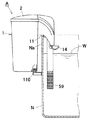
前記装置本体1は、合成樹脂などから槽状に形成されており、その前端には、図3に示すように、水槽Nの側壁Na上端に掛け止めするために、湾曲して下方へ垂れる掛け部11が一体形成されており、また、右部には、吸水配管配設部12が形成される一方、左側後部には、図1に示すように、水槽Nから吸い上げた水Wを清浄化するための浄水化槽部13が形成されている。また、前記掛け部11の左部上面11aは、浄化後の清浄水Wを前記水槽N内に放出するための流下壁面となっている。
The apparatus
なお、装置本体1の下面には、図3に示すように、水槽Nに掛け止めした状態での傾き姿勢を是正するために、回動操作で前方への突出量が変化する偏心した水平調整つまみ110が設けられている。また、前記流下壁面11aの先端下部には、清浄水Wを左右に振り分けて水槽N内に広範囲に放散させる振り分け部14が設けられている。
As shown in FIG. 3, the lower surface of the apparatus
前記吸水配管配設部12の後部は、深い有底孔部15が形成されており、その底壁下部が前記ポンプ部4となっている。
A deep bottomed
このポンプ部4は、図4に示すように、モータ41と、このモータ41で駆動されて、吸水メインパイプ51内に吸引力を作用させるインペラーユニット42とを有している。
As shown in FIG. 4, the
前記蓋体2は、装置本体1の開口を着脱可能に覆うものである。
The
前記吸水配管部5は、前記吸水配管配設部12に配置された逆L字形の吸水メインパイプ51を備えている。この吸水メインパイプ51の外端部には、水槽Nの水Wに浸漬されるストレナーパイプ59の上端部が接続されている。なお、ストレナーパイプ59の下端部には、円筒形のストレナースポンジ(図示せず)が装着されるようになっている。
The water
また、前記吸水メインパイプ51の内端部には、吸水流量調整部52が装備されており、その下流側には、垂直パイプ53が接続されている。
A water absorption flow
この垂直パイプ53の下端部には、前記インペラー42などを取り囲むモータ接続パイプ54が接続され、その周壁には、吸水した水Wを浄水化槽部13に供給させるための給水管55が接続されている。
A
前記吸水流量調整部52は、例えば図6および図7に示すように、前記吸水メインパイプ51の内端側開口に回動可能に内嵌して装着された筒部521と、この筒部521の先端に連結されて径方向外方へ突出する流量調整つまみ522とからなる。
For example, as shown in FIGS. 6 and 7, the water absorption flow
前記筒部521の周壁には、吸水メインパイプ51と垂直パイプ53との接続部の開口面積を可変させる切り欠き523が形成されており、前記流量調整つまみ522の回動操作による筒部521の回動量に応じて吸水メインパイプ51から垂直パイプ53への流量が調整されるようになっている。
A
前記給水管55には、吸気筒部56が設けられており、この吸気筒部56には、図5に示すように、ゴム管などの可撓性材からなる空気導入管57の下端が接続されている。なお、前記給水管55における吸気筒部56よりも上流側内面部位55aのリブ及び給水管内部形状は、図5に示すように、吸気のために負圧を生起させる構造が採用されている。なお、吸い込まれた空気は、水Wと共に前記浄水化槽13内に供給される。
The
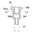
前記空気導入管56の上端開口には、空気流量調整部材58が接続されている。
An air flow
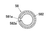
この空気流量調整部材58は、図8および図9に示すように、前記空気導入管56に接続された筒形のつまみ受け体581と、このつまみ受け体581の上部に回動可能に内嵌された空気流量調整つまみ582とからなる。
As shown in FIGS. 8 and 9, the air flow
前記つまみ受け体581の周壁には、縦溝581aが形成される一方、空気流量調整つまみ582の周壁には、開口582aが形成されている。この空気流量調整つまみ582を回動操作した際の前記縦溝581aと開口582aとの重なり量により、空気の吸い込み量が調整されるようになっている。
A
前記浄化槽部13には、前記フィルタユニット6と、このフィルタユニット6の上流側に配設された前記濾過材収容ユニット7とが収容されている。
The
フィルタユニット6は、図12に示すように、前記浄水化槽部13の左右の差し込み溝131,131間に差し込まれた合成樹脂製の長方形の多孔基板61と、この多孔基板61の上流側および下流側面にそれぞれ装着されたフィルタ部材62,63とからなる。
As shown in FIG. 12, the
各フィルタ部材62,63内には、活性炭Qが保持されている。
Activated carbon Q is held in the
前記濾過材収容ユニット7は、図11および図12に示すように、前記浄水化漕13における左右の差し込み溝132,132に差し込まれたユニット基板71と、カバー72とからなり、ユニット基板71とカバー72との間で形成される濾過材収容室76に濾過材MA,MB,MCが収容されるようになっている。
As shown in FIGS. 11 and 12, the filter
前記ユニット基板71は、合成樹脂などにより正面形状が略長方形に形成されており、その上流側面71aには、前記カバー72を着脱可能に装着させるために、上部および下部左右に位置して3つの係合孔711・・・がそれぞれ形成されている。
The
また、前記上流側面71aには、装着状態でのカバー72の開口周囲を緊密に取り囲む環状のリブ712が形成されている。なお、上部には、交換時に、引上げるための把手部713が形成されている。
The
前記カバー72は、合成樹脂などにより4角形の容器状に成形されており、その開口端部には、前記係合孔711・・・にそれぞれ係脱可能に係合される3つの係止爪片721が一体形成されている。
The
また、このカバー72の側壁72aの内面には、左右に位置して、複数段、例えば2段の水平桟部73A,73Bが設けられており、これら2段の左右の水平桟部73A,73Bには、それぞれ全域に小孔74が形成された2つの多孔仕切り板75A,75Bがそれぞれ取り外し可能に挿入・支持されている。
Further, the inner surface of the
これら2つの多孔仕切り板75A,75Bにより、前記カバー72内、つまり濾過材収容室76は、上下方向で3段の濾過材収容分室76A,76B,76Cとなっており、これら濾過材収容分室76A,76B,76Cには、生物の飼育などの適した清浄水Wを得るために、例えば種類の異なる濾過材MA,MB,MCが収容されている。
By these two
また、前記最下段の濾過材収容分室76Aに対応して前記カバー72の側壁72aおよび底壁72bには、前記吸水管55から流入した水Wに対する多数の流入小孔77が全域に形成されている。なお、この流入小孔77は、側壁72aおよび底壁72bのいずれか一方に設けてあればよい。
In addition, a large number of inflow
前記最上段の濾過材収容分室76Cに対応して、前記ユニット基板71の上部には、該濾過材収容室70を通過した水Wを流出させる多数の流出小孔78が形成されている。また、前記ユニット基板71の前記カバ−72の対応する領域外にも同様の流出小孔78が形成されている。
Corresponding to the uppermost filter
つぎに、上記構成の濾過装置の使用手順を説明する。 Next, a procedure for using the filtration device having the above-described configuration will be described.
まず、前記浄水化槽13内に前記フィルタユニット6および濾過材収容ユニット7を配置しておく。一方、前記吸水配管配設部12に逆L字形の吸水メインパイプ51などを配備する。
First, the
なお、ここでは、濾過材収容ユニット7における最下段(最上流側)の濾過材収容分室76Aに、例えばリング状のセラミックからなる濾過材MA、次段の濾過材収容分室76Bにスポンジからなる濾過材MB、最上段(最下流側)の濾過材収容分室76Cに不織布からなる濾過材MCがそれぞれ収容されている。
Here, in the filter
そして、前記掛け止め部11を水槽Nの側壁上端に引っかけるようににて濾過装置Aをセットする。この時、前記水平調整つまみ110を廻して濾過装置Aが水平姿勢に保持されるように調整する。
And the filtration apparatus A is set so that the said latching
また、前記ストレーナーパイプ52の下端部が水槽Nの水位よりも十分下方に位置するように長さを調整する。なお、このストレーナーパイプ59の下端部には、ストレーナースポンジを装着しておく。また、浄水化糟部13及びモータ41収容部に呼び水を入れてモータ41を起動させる。
Further, the length is adjusted so that the lower end portion of the
前記モータ41を起動させると、図10に示すように、インペラーユニット42が回転し、前記吸水メインパイプ51内に吸引力が作用し、前記水槽N内の水Wの吸水が開始される。すると、水Wは、ストレーナパイプ52で塵埃が除去されながら吸引メインパイプ51および垂直パイプ53を経て給水管55から浄水化槽13内に供給される。
When the
なお、この時の吸水流量は、前記吸水流量調整部52における流量調整つまみ522を回動操作して行う。また、前記空気流量調整部材58におけるつまみ582を回動操作して空気を導入させれば、給水管55を通して空気が前記浄水化槽13内に送給される。
The water absorption flow at this time is performed by rotating the
前記浄水化槽13内に供給された水Wの水位が増してくると、この水Wは、前記濾過材収容ユニット7におけるカバー72の側壁72aおよび底壁72bの各流入小孔77から最下段の濾過材収容分室76Aに流入する。
When the water level of the water W supplied into the
この最下段の濾過材収容分室76Aには、リング状のセラミックからなる濾過材MAが収容されているので、前記水Wは、濾過材収容分室76A内を回り巡りながら濾過材MAに接触することによる第1段階での濾過作用により浄化される。
Since the lowermost filter
なお、前記浄水化槽13内に供給された水Wは、前記カバー72のおける側壁72aおよび底壁72bにおける多数の流入小孔77から最下段の濾過材収容分室76A内に流入するので、一箇所から流入するものと違って該濾過材収容分室76A内の広範囲に行き渡り、全域の濾過材MAと接触して濾過性が高められる。
Note that the water W supplied into the
そして、水位の上昇に伴って、水Wは、最下段の濾過材収容分室76Aから下部の多孔仕切り板75Aの孔74を通過して中段の濾過材収容分室76Bに入り、ここのスポンジMBで接触されることによる第2段階での濾過作用により一層浄化される。
As the water level rises, the water W passes from the lowermost filter
この浄化された水Wは、さらに上部の多孔仕切り板75Bの小孔74を通過して前記最上段の濾過材収容分室76Cに流入する。そして、ここに収容されている不織布MCによる第3段階での濾過作用により浄化される。この後、前記ユニット基板71の上部の流出小孔78からフィルタユニット6側に流下する。
The purified water W further passes through the
このように、濾過材収容ユニット7における濾過材収容室76を複数段に別けて濾過材収容分室76A,76B,76Cとしたので、複数種の濾過材MA,MB,MCを流れ方向で順序的に収容することができ、これにより生物に応じた高度の清浄水Wを容易に得ることができる。
As described above, the filter
また、前記濾過材収容室76を複数段に分ける多孔仕切り板75A,75Bが取り外し可能であるので、上記濾過材収容分室の数を低減して、上記とは異なる清浄水を得ることができる。
Moreover, since the
なお、前記フィルタユニット6に至った水Wは、所定の濾過作用を受けて浄化され、清浄水Wとなって前記流下壁面11aを流下し、振り分け部14を介して左右へ振り分けられながら水槽N内に放散される。このような濾過動作により、水Wが循環され、水槽N内の水Wの清浄化が進むことになる。
The water W that has reached the
図13及び図14は、この発明の濾過材収容ユニットの第2実施形態を示すもので、前記浄水化漕13における左右の差し込み溝132,132に差し込まれるユニット基板81と、カバー82とからなり、ユニット基板81とカバー82との間で形成される濾過材収容室86に濾過材MA,MB,MCが収容されるようになっているという構成は、先の第1実施形態の濾過材収容ユニット7と同様である。
FIGS. 13 and 14 show a second embodiment of the filter medium accommodation unit of the present invention, which comprises a
この第2実施形態の濾過材収容ユニット8が、先の第1実施形態の濾過材収容ユニット7と相違する点は、カバー82の側壁に突設された流入管83の開口がポンプ部に繋がる給水管の開口に臨んで水槽内の水が濾過材収容ユニット8内に取り込まれるものとなされると共に、取り込まれた水Wの全てが最下段の濾過材収容分室86Aの下方から順次、中段の濾過材収容分室86B、最上段の濾過材収容分室86Cを通過していく点にある。そのために、流入管83から取り込まれた水を、必ず最下段の濾過材収容分室86A下方へ導くための隔壁90がカバー82内に設けられている。
The filter
すなわち、図13に示すように、該隔壁90は、流入管83に臨む開口を有する側壁と対向する垂壁部90aと、該垂壁部上部からカバー側壁に連なる天井部90bとから構成されている。前記垂壁部90aは、最下段の濾過材収容分室86Aの一側壁となると共に、天井部90bから吊り下げられたような態様に形成され、垂壁部90aの下端は、カバー底壁から距離を置いた状態に位置するものと設定されている。
That is, as shown in FIG. 13, the
該隔壁の下端部に連なるように櫛歯状の最下段濾過材収容分室用仕切板部85aが水平状に設けられる一方、その上方には複数段の多孔仕切板85b、85cが着脱自在に設けられている。各多孔仕切板85b、85cには多数個の横長スリット84…が並列状態に配置されている。
A comb-like bottom-stage filter material accommodation
なお、図中821は、後述するユニット基板81の係合孔811・・・に係脱可能に係合される係止爪片、83A、83Bは、多孔仕切り板85b,85cを支持するための水平桟部である。
In the figure,
前記ユニット基板81は、合成樹脂などにより正面形状が略長方形に形成されており、その前記カバー82を着脱可能に装着させるために、上部および下部左右に位置して3つの係合孔811・・・がそれぞれ形成されている。
また、前記ユニット基板81には、装着状態でのカバー872の開口周囲を緊密に取り囲む環状のリブ812が形成されている。なお、上部には、交換時に、引上げるための把手部813が形成されている。
The
このユニット基板81下部の前記リブの812の外側には、複数個のスリット孔87…が高さ方向に並べて配置されている。このスリット孔87は、給水管55以外のすき間から漏れた水が、浄化水糟部13からオーバーフローしないように、直接、フィルタユニット6に向かって通り抜けるためのものである。
A plurality of slit holes 87 are arranged in the height direction outside the
このユニット基板81の上部には、該濾過材収容室86を通過した水Wを流出させる多数の流出スリット孔88が形成されている。また、前記ユニット基板81の前記カバ−82の対応する領域外にはオーバーフロー用の流出スリット孔88が形成されている。
A large number of outflow slit holes 88 through which the water W that has passed through the filter
この第2実施形態の濾過材収容ユニット8を用いた濾過装置の使用手順について以下に説明するが、水槽内の水を浄水化層13内に供給するまでの操作は第1実施形態の濾過材収容ユニット7を用いた濾過装置と同様である。
The procedure for using the filter device using the filter
而して、浄水化糟部13に呼び水を満たした後、モータ41を起動させると、吸引された水槽内Nの水が、給水管55からカバー82の流入管83に放出されてユニット内部に流入することになる。ユニット内部には隔壁90が設けられているので、ユニット内部に流入した水Wは、下方から最下段の濾過材収容分室86Aに流入し、第1段階の濾過が行われる。
Thus, when the
さらに、水位の上昇に伴って、水Wは、順次上位の濾過材収容分室86B、86Cに流入し、第2段階及び第3段階の濾過が行われる。この後、前記ユニット基板81の上部の流出スリット88からフィルタユニット61側に流下する。
Further, as the water level rises, the water W sequentially flows into the upper filter medium
この第2実施形態の濾過材収容ユニット8を用いた濾過装置は、第1実施形態の実施形態の濾過材収容ユニット8を用いた濾過装置と同様又はそれ以上の効果を奏する。
The filtration apparatus using the filter
すなわち、濾過材収容ユニット8における濾過材収容室86を複数段に別けて濾過材収容分室86A,86B,86Cとしたので、複数種の濾過材MA,MB,MCを流れ方向で順序的に収容することができ、これにより生物に応じた高度の清浄水Wを容易に得ることができる。しかも、ユニット内部に流入した水Wは、下方から最下段の濾過材収容分室86Aに流入するので、最下段の濾過材収容分室86A内の濾過材MA全域の濾過材MAと接触して濾過性が高められる。
In other words, the filter
また、前記濾過材収容室86を複数段に分ける多孔仕切り板85A,85Bが取り外し可能であるので、上記濾過材収容分室の数を低減して、上記とは異なる清浄水を得ることができる。
Moreover, since the porous partition plates 85A and 85B that divide the filter
なお、前記フィルタユニット61に至った水Wは、所定の濾過作用を受けて浄化され、清浄水Wとなって前記流下壁面11aを流下し、振り分け部14を介して左右へ振り分けられながら水槽N内に放散される。このような濾過動作により、水Wが循環され、水槽N内の水Wの清浄化が進むことになる。
The water W that has reached the
6・・・・・・・・・・フィルタユニット
7・・・・・・・・・・濾過材収容ユニット
13・・・・・・・・・浄水化槽部
71・・・・・・・・・ユニット基板
71a・・・・・・・・ユニット基板の上流側面
72・・・・・・・・・カバー
72a・・・・・・・・カバーの側壁
72b・・・・・・・・カバーの底壁
75A,75B・・・・多孔仕切り板
76・・・・・・・・・濾過材収容室
76A,76B・・・・濾過材収容分室
77・・・・・・・・・流入小孔
78・・・・・・・・・流出小孔
MA,MB,MC・・・濾過材
6 ··············································································································· ······································································································ The bottom wall of the
Claims (5)
前記濾過材収容室内に、該濾過材収容室内を上下方向で複数に分室する一つもしくは複数の多孔仕切り板を着脱可能に配置し、
最下段の濾過材収容分室内に対応するカバーの周壁及び底壁のうちの少なくとも一方から水槽内から汲み上げられた水を取り込むものとし、
前記ユニット基板における前記最上段の濾過分室に対応する領域に、最上段の該濾過室を通過した水を流出させる多数の流出用孔を形成したことを特徴とする水槽用外掛け式濾過装置における濾過材収容ユニット。 Located on the upstream side of the filter disposed across the water purification tank section, the unit board that is installed so as to be detachable across the water purification tank section, and the upstream side surface of this unit board can be attached and detached. In the filter medium accommodation unit in the water tank external filtration device in which the filter medium accommodation chamber is constituted by a cover that is tightly mounted as possible,
In the filter medium containing chamber, one or more porous partition plates that divide the filter medium containing chamber into a plurality in the vertical direction are detachably disposed,
The water pumped up from the water tank is taken in from at least one of the peripheral wall and the bottom wall of the cover corresponding to the lowermost filter medium accommodation compartment,
In the external filtration device for an aquarium, a large number of outflow holes for allowing the water that has passed through the uppermost filtration chamber to flow out are formed in an area corresponding to the uppermost filtration compartment on the unit substrate. Filter media storage unit.
An overhanging filter device for an aquarium, comprising the filter medium accommodation unit according to any one of claims 1 to 4.
Priority Applications (1)
| Application Number | Priority Date | Filing Date | Title |
|---|---|---|---|
| JP2004380517A JP4079941B2 (en) | 2004-12-28 | 2004-12-28 | Filter medium accommodation unit in water tank outer filtration apparatus and water tank outer filtration apparatus comprising the filter medium accommodation unit |
Applications Claiming Priority (1)
| Application Number | Priority Date | Filing Date | Title |
|---|---|---|---|
| JP2004380517A JP4079941B2 (en) | 2004-12-28 | 2004-12-28 | Filter medium accommodation unit in water tank outer filtration apparatus and water tank outer filtration apparatus comprising the filter medium accommodation unit |
Publications (3)
| Publication Number | Publication Date |
|---|---|
| JP2006180833A JP2006180833A (en) | 2006-07-13 |
| JP2006180833A5 JP2006180833A5 (en) | 2007-02-08 |
| JP4079941B2 true JP4079941B2 (en) | 2008-04-23 |
Family
ID=36734368
Family Applications (1)
| Application Number | Title | Priority Date | Filing Date |
|---|---|---|---|
| JP2004380517A Active JP4079941B2 (en) | 2004-12-28 | 2004-12-28 | Filter medium accommodation unit in water tank outer filtration apparatus and water tank outer filtration apparatus comprising the filter medium accommodation unit |
Country Status (1)
| Country | Link |
|---|---|
| JP (1) | JP4079941B2 (en) |
Families Citing this family (3)
| Publication number | Priority date | Publication date | Assignee | Title |
|---|---|---|---|---|
| KR101149557B1 (en) | 2010-02-24 | 2012-05-30 | (주)삼호무역 | Rack type filter |
| KR101149555B1 (en) | 2010-02-24 | 2012-05-30 | (주)삼호무역 | Rack type filter |
| KR101941204B1 (en) * | 2018-05-21 | 2019-01-22 | 한은하 | Hanger type overflow apparatus |
-
2004
- 2004-12-28 JP JP2004380517A patent/JP4079941B2/en active Active
Also Published As
| Publication number | Publication date |
|---|---|
| JP2006180833A (en) | 2006-07-13 |
Similar Documents
| Publication | Publication Date | Title |
|---|---|---|
| EP1793664B1 (en) | Aquarium filter cartridge | |
| US7618534B2 (en) | Aquarium filter | |
| JP5210042B2 (en) | Underwater organism rearing system and water tank purification unit | |
| JP5584714B2 (en) | Air-driven filter device | |
| JP2585671Y2 (en) | Ornamental fish tank filtration device | |
| JP2015506683A (en) | Water tank with filtration function | |
| JP2005521394A (en) | Filtration device | |
| JP2007037548A (en) | Filter apparatus with fluid bypass | |
| US8017007B2 (en) | Filtering unit for an aquarium | |
| JP4079941B2 (en) | Filter medium accommodation unit in water tank outer filtration apparatus and water tank outer filtration apparatus comprising the filter medium accommodation unit | |
| JP2009254317A (en) | Filter device for aquarium fish tank | |
| JP3711187B2 (en) | Water tank filter | |
| JP2006230212A (en) | Apparatus for filtering water tank for aquarium fish | |
| JPH11215933A (en) | Table top-type water tank | |
| JP3653014B2 (en) | Water tank filter | |
| TWM564913U (en) | Modular fish tank and filter unit thereof | |
| JPS58163415A (en) | Filter apparatus | |
| KR102265428B1 (en) | Box filter for aquarium | |
| AU2011202579B2 (en) | Aquarium filter assembly | |
| JP4145688B2 (en) | Upper filter | |
| JP2531451Y2 (en) | Fish tank for appreciation fish | |
| JP4615940B2 (en) | Water pump mounting structure for water tank filtration device | |
| JPH07328339A (en) | Filtration apparatus | |
| JP2506888Y2 (en) | Plant and water aquarium water purification device | |
| JP5780922B2 (en) | Internal filtration device |
Legal Events
| Date | Code | Title | Description |
|---|---|---|---|
| A521 | Written amendment |
Free format text: JAPANESE INTERMEDIATE CODE: A523 Effective date: 20061220 |
|
| A621 | Written request for application examination |
Free format text: JAPANESE INTERMEDIATE CODE: A621 Effective date: 20061220 |
|
| A977 | Report on retrieval |
Free format text: JAPANESE INTERMEDIATE CODE: A971007 Effective date: 20071221 |
|
| TRDD | Decision of grant or rejection written | ||
| A01 | Written decision to grant a patent or to grant a registration (utility model) |
Free format text: JAPANESE INTERMEDIATE CODE: A01 Effective date: 20080115 |
|
| A61 | First payment of annual fees (during grant procedure) |
Free format text: JAPANESE INTERMEDIATE CODE: A61 Effective date: 20080205 |
|
| FPAY | Renewal fee payment (event date is renewal date of database) |
Free format text: PAYMENT UNTIL: 20110215 Year of fee payment: 3 |
|
| R150 | Certificate of patent or registration of utility model |
Ref document number: 4079941 Country of ref document: JP Free format text: JAPANESE INTERMEDIATE CODE: R150 Free format text: JAPANESE INTERMEDIATE CODE: R150 |
|
| FPAY | Renewal fee payment (event date is renewal date of database) |
Free format text: PAYMENT UNTIL: 20110215 Year of fee payment: 3 |
|
| RD02 | Notification of acceptance of power of attorney |
Free format text: JAPANESE INTERMEDIATE CODE: R3D02 |
|
| FPAY | Renewal fee payment (event date is renewal date of database) |
Free format text: PAYMENT UNTIL: 20110215 Year of fee payment: 3 |
|
| FPAY | Renewal fee payment (event date is renewal date of database) |
Free format text: PAYMENT UNTIL: 20120215 Year of fee payment: 4 |
|
| FPAY | Renewal fee payment (event date is renewal date of database) |
Free format text: PAYMENT UNTIL: 20130215 Year of fee payment: 5 |
|
| FPAY | Renewal fee payment (event date is renewal date of database) |
Free format text: PAYMENT UNTIL: 20130215 Year of fee payment: 5 |
|
| FPAY | Renewal fee payment (event date is renewal date of database) |
Free format text: PAYMENT UNTIL: 20140215 Year of fee payment: 6 |
|
| R250 | Receipt of annual fees |
Free format text: JAPANESE INTERMEDIATE CODE: R250 |
|
| R250 | Receipt of annual fees |
Free format text: JAPANESE INTERMEDIATE CODE: R250 |
|
| R250 | Receipt of annual fees |
Free format text: JAPANESE INTERMEDIATE CODE: R250 |
|
| R250 | Receipt of annual fees |
Free format text: JAPANESE INTERMEDIATE CODE: R250 |