JP4078286B2 - Sheet feeding apparatus and image forming apparatus - Google Patents
Sheet feeding apparatus and image forming apparatus Download PDFInfo
- Publication number
- JP4078286B2 JP4078286B2 JP2003363201A JP2003363201A JP4078286B2 JP 4078286 B2 JP4078286 B2 JP 4078286B2 JP 2003363201 A JP2003363201 A JP 2003363201A JP 2003363201 A JP2003363201 A JP 2003363201A JP 4078286 B2 JP4078286 B2 JP 4078286B2
- Authority
- JP
- Japan
- Prior art keywords
- sheet
- heating
- heat generation
- sheet feeding
- sheets stacked
- Prior art date
- Legal status (The legal status is an assumption and is not a legal conclusion. Google has not performed a legal analysis and makes no representation as to the accuracy of the status listed.)
- Expired - Fee Related
Links
Images


Landscapes
- Paper Feeding For Electrophotography (AREA)
- Sheets, Magazines, And Separation Thereof (AREA)
Description
本発明は、加熱装置、シートを加熱するための加熱手段を有するシート給送装置並びに画像形成装置に関する。 The present invention relates to a heating apparatus, a sheet feeding apparatus having a heating unit for heating a sheet, and an image forming apparatus.
従来、複写機やレーザービームプリンタ等の画像形成装置においては、感光ドラム上にトナー像を形成し、このトナー像をシート積載手段である給紙カセットから送り出されたシートに転写し、この後、定着部でシートを加熱、加圧することによりトナー像をシートに定着させるようにしている。 Conventionally, in an image forming apparatus such as a copying machine or a laser beam printer, a toner image is formed on a photosensitive drum, and the toner image is transferred to a sheet fed from a sheet feeding cassette as a sheet stacking unit. The toner image is fixed on the sheet by heating and pressurizing the sheet in the fixing unit.
しかし、このような画像形成装置において、シートが多量に吸湿している場合、即ち多量の水分を含んでいる場合には、シートの体積抵抗率が下がるため、トナー像が転写されている間、シートが転写位置以外の接地部で短絡することがある。そして、このように転写位置以外で短絡した場合には、転写電流が良好に働かず、転写不良を起こし、この結果画像不良が生じるという問題があった。また、シートが多量に吸湿している場合、定着部に設けられた定着ローラを通過する際にしわが発生しやすいという問題もある。 However, in such an image forming apparatus, when the sheet absorbs a large amount of moisture, that is, when it contains a large amount of moisture, the volume resistivity of the sheet decreases, so that while the toner image is being transferred, The sheet may short-circuit at a grounding part other than the transfer position. When a short circuit occurs at a position other than the transfer position as described above, there is a problem that the transfer current does not work well and a transfer failure occurs, resulting in an image failure. Further, when the sheet absorbs a large amount of moisture, there is a problem that wrinkles are likely to occur when the sheet passes through a fixing roller provided in the fixing unit.
さらに、一般的にシートが多量に吸湿している場合、定着部で加熱、加圧した場合にはカール量が大きくなり、このため定着後、シートが定着ローラに巻きついてしまい紙詰まりを発生させる等の不具合が生じる。また、シートの両面に画像形成を行う場合には、1面目の画像形成の際に発生したカールにより、2面目の画像形成の際に、シートが感光ドラムに巻き付くという不具合が生じる。 Furthermore, in general, when the sheet absorbs a large amount of moisture, the amount of curling increases when heated and pressed in the fixing unit. For this reason, after fixing, the sheet wraps around the fixing roller and causes a paper jam. Such problems occur. In addition, when image formation is performed on both sides of a sheet, there is a problem that the sheet is wound around the photosensitive drum when the image is formed on the second side due to the curl generated at the time of image formation on the first side.
そこで、以上のような問題を解決するため、従来は、例えばシートの下方に加熱装置を設置し、この加熱装置によりシートを加熱してシートの除湿を行うことが提案されている(例えば、特許文献1参照。)。 Therefore, in order to solve the above problems, conventionally, for example, it has been proposed to install a heating device below the sheet and heat the sheet with this heating device to dehumidify the sheet (for example, patents). Reference 1).
図8は、このような従来の加熱装置の構成を示す図であり、この加熱装置は、ヒータ80と、ヒータ80が取り付けられた放熱板81とを備えている。そして、放熱板81をヒータ取付け面を下側にし、画像形成装置の底板101と、シートSとの間に配置することにより、シートSを下方から加熱するようにしている。なお、ヒータ80には、画像形成装置に内蔵された電源、または外部電源などから給電が行われている。
ところで、このような加熱装置を備えた従来の画像形成装置において、近年のユーザーの画像形成装置に対する小型化、省エネルギー化といった要求によって、スペース的、効率的な面から加熱装置はシートSを積載する給紙カセットの下方に近接して設置することを余儀なくされる場合が多い。 By the way, in the conventional image forming apparatus provided with such a heating device, the heating device stacks the sheets S from the viewpoint of space and efficiency in response to the recent demands for downsizing and energy saving of the image forming device by the user. In many cases, it is necessary to install the paper cassette close to the lower side of the paper feed cassette.
ところが、このように加熱装置を給紙カセットの下方に近接して設置した場合、ヒータの配置に基づく温度分布がそのまま放熱板直上のシート表面へ影響し、この結果、シートSが局部的に加熱され、シートSの湿度分布及び温度分布が著しく偏ってしまう場合がある。 However, when the heating device is installed close to the lower side of the sheet feeding cassette as described above, the temperature distribution based on the heater arrangement directly affects the sheet surface immediately above the heat radiating plate. As a result, the sheet S is locally heated. As a result, the humidity distribution and temperature distribution of the sheet S may be significantly biased.
そして、このようにシートの湿度分布及び温度分布が著しく偏った場合、図9に示すように、シートSが波打ち変形してしまい、この状態でシートSが転写部まで搬送されると、部分的に転写不良などを引き起こしてしまうという不具合が発生する。 If the humidity distribution and the temperature distribution of the sheet are significantly deviated as described above, the sheet S is waved and deformed as shown in FIG. This causes a problem of causing a transfer failure or the like.
ここで、こうした不具合を解決するためには、加熱装置を給紙カセット(シート)から離した位置に配置し、かつ最大サイズのシートを均一に温めることができるよう細かく、かつ広くヒータを配設する必要があるが、こうした構成をとった場合には、加熱装置の大型化、高コスト化につながる。また、シートSはカットされている端部に近い方が、含有した水分が抜け出やすいため、上記のように単に均一にシートSを加熱した場合には、シートSの中央部に水分が多く残ってしまう恐れもある。 Here, in order to solve such problems, the heating device is arranged at a position away from the sheet feeding cassette (sheet), and the heater is arranged finely and widely so that the maximum size sheet can be uniformly heated. However, when such a configuration is adopted, the heating device is increased in size and cost. Further, since the moisture contained in the sheet S is easier to escape when the sheet S is closer to the cut end, when the sheet S is simply heated as described above, a large amount of moisture remains in the central portion of the sheet S. There is also a risk.
また、最大のサイズのシートに合わせて加熱装置を設置した場合、小サイズのシートSをセットするとシートSに供給する熱量が過多となり、この結果、効率が悪くなるばかりでなく、画像形成装置本体内の昇温を引き起こすようになる。 In addition, when the heating device is installed in accordance with the maximum size sheet, when the small size sheet S is set, the amount of heat supplied to the sheet S becomes excessive. As a result, not only the efficiency is deteriorated but also the main body of the image forming apparatus. It will cause a rise in temperature.
ここで、電子写真方式により感光ドラムにトナー像を形成する画像形成装置の場合、温度や湿度の影響を受けやすく、特に感光ドラムとして用いられる感光体は温度によってその特性に影響が出るため、画像がかすれたり、にじんだりするという画像弊害が発生することが知られている。したがって、このように画像形成装置本体内の昇温が引き起こされ、昇温の影響が感光ドラムにまで及んだ場合には、画像欠陥も生ずるという不具合を引き起こしてしまう。 Here, in the case of an image forming apparatus that forms a toner image on a photosensitive drum by an electrophotographic method, it is easily affected by temperature and humidity. In particular, the characteristics of a photoconductor used as a photosensitive drum are affected by temperature. It is known that an image detrimental effect such as fading or blurring occurs. Therefore, when the temperature rise in the image forming apparatus main body is caused as described above and the influence of the temperature rise reaches the photosensitive drum, a problem that an image defect is caused is caused.
本発明はこのような現状に鑑みてなされたものであり、適切かつ効率的にシートの除湿を行うことのできる画像形成装置を提供することを目的とするものである。 SUMMARY An advantage of some aspects of the invention is that it provides an image forming apparatus capable of dehumidifying a sheet appropriately and efficiently.
本発明は、シートを積載するシート積載手段と、前記シート積載手段に積載されたシートを給送するためのシート給送手段と、前記シート積載手段に積載されたシートを加熱する加熱手段と、を備え、前記加熱手段は、前記加熱手段の発熱領域のうち、前記シート積載手段に積載されたシートの中央部に対する発熱領域の発熱量が他の発熱領域の発熱量よりも多くなるように構成されている。 The present invention includes a sheet stacking unit for stacking sheets, a sheet feeding unit for feeding the sheets stacked on the sheet stacking unit, a heating unit for heating the sheets stacked on the sheet stacking unit, And the heating means is configured such that, of the heat generation area of the heating means, the heat generation amount of the heat generation area with respect to the central portion of the sheets stacked on the sheet stacking means is larger than the heat generation amount of the other heat generation areas. Has been.
本願発明は、上記構成によって、効率的にシートの除湿ができるシート給送装置を提供できる。 The present invention can provide a sheet feeding apparatus capable of efficiently dehumidifying sheets by the above-described configuration.
以下、本発明の実施の形態について図面を用いて詳細に説明する。 Hereinafter, embodiments of the present invention will be described in detail with reference to the drawings.
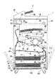
図2は、本発明の第1の実施の形態に係る画像形成装置の概略構成を示す図である。同図において、1は画像形成装置、1Aは画像形成装置本体(以下、装置本体という)であり、この画像形成装置1は、装置本体1Aの上部に設けられた画像読取部1Bと、画像読取部1Bの下方に配置された画像形成部1Cと、画像形成部1CにシートSを給送するシート給送装置1Dとを備えている。
FIG. 2 is a diagram showing a schematic configuration of the image forming apparatus according to the first embodiment of the present invention. In FIG. 1,
ここで、画像読取部1Bは、原稿台58にセットされた原稿Gを順次一枚ずつ読み取り位置59に搬送する自動原稿給紙装置57と、読み取り位置59に搬送された原稿に光を照射する不図示の光源、原稿Gから反射した後の反射光が折り返しミラー60〜62を経て導かれるCCD等の画像読み取り素子63とを有する光学系とを備えている。
Here, the
また、画像形成部1Cは、感光体ドラム52、感光体ドラム上に静電潜像を形成するためのレーザスキャナ50A、感光体ドラム上に形成された静電潜像をトナーにより現像して感光体ドラム上にトナー像を形成する現像器53、感光体ドラム上に形成されたトナー像をシートSに転写させる転写装置54を備えている。
In addition, the image forming unit 1C develops the electrostatic latent image formed on the
なお、同図において、100は放熱板102と、放熱板102の下方に配置された加熱手段であるワイヤ状のヒータ103とを備えた加熱装置であり、この加熱装置100は、ヒータ103からの熱によりシートSを加熱するようにしている。
In the figure,
シート給送装置1Dは、シートSを積載するシート積載手段として給紙カセット39に設けられているシートトレイ90と、シートトレイ90に積載されているシートSを給送するシート給送手段としての給紙ローラ40と、この給紙ローラ40により送り出されたシートSを一枚ずつ分離するためのフィードローラ41とリタードローラ42とにより構成される分離部と、加熱装置100とを有している。なお、図2に示すように、シートトレイ90に積載されたシートの表面と略平行に加熱手段100が設けられている。
The sheet feeding apparatus 1D serves as a
次に、このような構成の画像形成装置1における画像形成動作について説明する。
Next, an image forming operation in the
シートSに画像を形成する場合は、まず自動原稿給紙装置57の原稿台58に原稿Gをセットし、この後、コピーボタンを押すと自動原稿給紙装置57により原稿Gが読み取り位置59に搬送される。そして、この原稿Gに対して不図示の光源から光を照射し、その反射光を折り返しミラー60〜62を経て、画像読み取り素子63に導いた後、画像読み取り素子63により画像信号に変換し、この画像信号を画像形成部1Cのレーザスキャナ50Aに転送する。
When an image is formed on the sheet S, first, the document G is set on the document table 58 of the
なお、このレーザスキャナ50Aは、不図示のレーザ発振器と、ポリゴンミラー50とを備えており、画像読み取り素子63からの画像信号が入力されると、レーザ発振器から画像信号に対応してレーザ光が発せられ、このレーザ光が回転しているポリゴンミラー50に反射され、更に反射ミラー51で再び折り返される事で感光ドラム52上に照射されるようになっている。
The
そして、このようにレーザスキャナ50Aから照射されたレーザ光により感光体ドラム52が走査され、感光体ドラム52上に静電潜像が形成される。この後、この静電潜像は現像器53により現像されてトナー像として可視化される。
Then, the
また、このようなトナー像形成動作と並行して給紙ローラ40が回転してシートSを送り出し、この後、シートSはフィードローラ41とリタードローラ42とにより構成される分離部により1枚ずつ分離され後、レジストローラ対43によりレジスト補正が行われる。
Further, in parallel with such a toner image forming operation, the
この後、このようにレジストローラ対43によりレジスト補正が行われたシートSは、感光ドラム52と転写装置54とにより構成される転写部へと搬送され、この転写部において転写装置54にトナー像と逆極性の電圧を印加することにより、トナー像が転写される。
Thereafter, the sheet S subjected to the registration correction by the
次に、トナー像が転写されたシートを搬送部44により定着ローラ対55,56に搬送し、この定着ローラ対55,56によってシートSを加熱、加圧することにより、トナー像をシート上に永久定着する。そして、このようにしてトナー像を定着した後、第1面にのみ画像を形成する片面コピーの場合には、シートSを装置本体外に設けられた不図示の排紙トレイに排出する。
Next, the sheet onto which the toner image has been transferred is conveyed to the fixing
なお、シートSは、排出トレイ以外に同図に示すように画像形成部1Cと画像読取部1Bとの間に形成された上面排紙部48に排出することも可能である。この場合、定着ローラ対55、56から排出されたシートSは、その後、切り替えフラッパ10を経て、反転ローラ対45及び排紙ローラ対46を経て上面排紙部48上に排出積載される。
In addition to the discharge tray, the sheet S can be discharged to an upper
ここで、このように上面排紙部48にシートSを排出する場合、排出トレイ上に排出する場合と異なり、シートSは、画像面を下側に向けた形で順次重ねて出力積載されてゆくので、出力が全て終了した時点では出力順に積載されていることとなる。このため、コンピューターなどからの出力方法としては、こちらの方が一般的な排出方法である。
Here, when discharging the sheet S to the upper
一方、第2面にも画像を形成する両面コピーの場合は、片面に画像を転写されたシートSを、定着ローラ対55,56を通過した後、反転ローラ対45の反転及び切り替えフラッパ10の切り換えにより反転パス71に向けて搬送する。
On the other hand, in the case of duplex copying in which an image is also formed on the second side, the sheet S having the image transferred on one side passes through the fixing
次に、このように反転パス71に向けて搬送したシートSの後端が反転パス71に設けられた反転切り替え用の弾性シート70を通過すると、反転ローラ47が逆転し、これによりシートSは弾性シート70の作用により、両面パス72内に進入する。そして、このように両面パス72に進入した後、シートSは再度転写部に搬送されて画像が転写され、この後定着ローラ対55,56を通過することで、2面目の画像がシート上に形成される。
Next, when the trailing edge of the sheet S conveyed toward the reversing
ところで、シートSはカットされている端部に近い方が、含有した水分が抜け出やすい(乾燥し易い)ため、ただ単に均一にシートSを加熱した場合には、シートSの中央部に水分が多く残ってしまう事になる。 By the way, since the sheet S is closer to the cut end, the contained moisture is more likely to escape (is easy to dry). Therefore, when the sheet S is simply heated uniformly, moisture is present at the center of the sheet S. Many will remain.
ここで、このように水分が中央部に多く残っている場合には、その部分において転写電流がシートSを通して流れてしまう等の現象を引き起こし、そのことが原因で画像上の障害を引き起こすため、出来るだけシート中央部の乾燥効率を上げる必要がある。 Here, when a large amount of moisture remains in the central portion as described above, a phenomenon such as a transfer current flowing through the sheet S occurs in the portion, and this causes a failure on the image. It is necessary to increase the drying efficiency in the center of the sheet as much as possible.
また、定着時における加熱の際、シートSに含まれた水分が蒸発することによって発生するカールにより、シートSが定着ローラ対55,56に巻き付くという現象は、シートSの搬送方向の前端部のカールが直接の発生要因となる。このため、シートの前端部も、また極力水分量を減らすように重点的に乾燥する必要がある。さらに、シートの裏面にも画像を形成する場合を想定すると、同様にシートSの後端部もまた乾燥効率を上げておくことが望ましい。
In addition, the phenomenon that the sheet S is wound around the fixing
そこで、本実施の形態において、ヒータ103は、図1に示すようにシートSの対角線方向に沿って、かつ交わることなく配置された発熱部分103a,103bと、矢印に示すシート搬送方向と直交する両端部であるシートSの前後端部に沿った形で配置された発熱部分103c,103dとを備えている。即ち、ワイヤ状のヒータ103は略8の字に配置されている。したがって、ヒータ103は、発熱部分103a,103bが集中しているヒータ103の発熱領域の中央部における発熱量が他の部分よりも多くなるように構成されている。
Therefore, in the present embodiment, the
そして、ヒータ103の発熱領域の中央部がシートSの中央部と一致するようにヒータ103を配置している。よって、ヒータ103の発熱領域のうち、シートSの中央部に対する発熱領域の発熱量が、シートの中央部に対する発熱領域以外の発熱領域の発熱量よりも多くなるようにヒータ103が構成されている。また、シートSにおけるシート搬送方向の前後端部に沿ってヒータ103が発熱するように、シートSの前後端部に対応する位置に発熱部分103c,103dが配置されている。上記のようなヒータ103によるシートSの熱分布は図3で示すような分布となる。つまり、ヒータ103の熱分布が、シートSの中央部と、前後端部とで高くなる。
The
このため、このような温度分布を持つヒータ103によりシートSを乾燥させた場合には、最も水分量が多く残りやすい中央部が、他の部分より多く加熱され、また同様に含有水分量を少なくしたいシート前後端部も、より多く加熱されることになる。この結果、シートSの中央部及び前後端部での水分量が確実に抑えられ、なおかつシートSを全体的にほぼ均等に乾燥させた状態にすることが可能となる。
For this reason, when the sheet S is dried by the
そして、シートSをこのような状態にすることにより、既述したような転写時における短絡という画像に及ぼす問題は発生せず、また端部のカールにより発生する感光ドラム52、定着ローラ対55,56へのシートSの巻き付き等の搬送上の弊害を抑えることが可能になる。
By setting the sheet S in such a state, there is no problem on the image of short circuit at the time of transfer as described above, and the
このように、シートSの概ね対角線に沿ってヒータ103の発熱部分103a、103bを配置することにより、シートSの中央部に対する発熱量を他の部分に比べて多くすることができる。また、少なくともシートSの先端部、本実施の形態においては、シートSの前後端部に対応する位置にヒータ103の発熱部分103c,103dを配置することにより、シート前後端部に対する発熱領域の発熱量を他の発熱領域の発熱量に比べて多くすることができる。これにより、シートSをより均一に乾燥させることができ、シートSの乾燥状態の不均一によって発生する画像上の諸問題を防止することが可能となる。
As described above, by disposing the
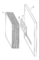
ところで、本実施の形態において、放熱板102は装置本体1Aの枠体の一部である底板101の上面に取り付けられている。
By the way, in this Embodiment, the
ここで、この底板101の上には装置全体1Aの全部品が組み立てられるため、その強度は極力頑強であることが望ましいことから、また加工上の容易さ、コストが安いこと等の理由から底板101としては、単に板金を折り曲げて構成したものではなく、絞り加工を加えたものが使用される。
Here, since all the parts of the
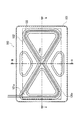
また、一般的には単に四辺を曲げた形状で底板101を構成するよりも、図4に示すようなX字状の凹凸からなる絞り形状が強度上有効であることが知られている。なおこれは、平板の構成に、斜めに絞りを追加することで、斜めに梁を渡した事と同様の効果が得られるためで、これにより底板に加わるX方向、Y方向の変形に対して強度を確保することができる。
In general, it is known that a diaphragm shape composed of X-shaped irregularities as shown in FIG. 4 is more effective in strength than simply forming the
そこで、本実施の形態においては、図5の(a)及び(b)で示されるように、底板101に絞り形状の凹部101aを形成することにより強度を確保している。さらに、この凹部101aをシートSの対角線に対応して形成すると共に、ヒータ103を、この底板101の凹部101aに沿って配置するようにしている。なお、図5(a)は図4におけるA−A断面を、図5(b)は図4におけるB−B断面をそれぞれ示している。
Therefore, in the present embodiment, as shown in FIGS. 5A and 5B, strength is ensured by forming a diaphragm-shaped
ここで、このように底板101の凹部101aに沿って、即ち凹部内にヒータ103を配置することにより、ヒータ103の部分の高さを考慮せずに、ヒータ103を配置することが可能となる。この結果、加熱装置全体の省スペース化が図れると共に、シートSとヒータ103との距離をより離すことができるようになる。なお、このようにヒータ103からシートSまでの距離を離すことは、ヒータ103による局所的な加熱を避ける点において有効であり、こうした構成をとることにより、さらにより均一なシートSの乾燥が可能になる。
Here, by arranging the
このように、ヒータ103を底板101に設けられた凹部101aに沿って配置することにより、加熱装置100のサイズを大きくすること無く、また装置本体1Aの枠体の強度を損なうことなく、シートSに対してのヒータ103の距離を確保することが可能となる。これにより、ヒータ103による局所的な過熱を避けることができ、より均一なシートSの加熱、除湿が可能となる。
Thus, by arranging the
ところで、これまでの説明においては、ワイヤ状の1本のヒータ103を図1に示すような位置に配した場合について述べてきたが、本発明はこれに限らず、ヒータを複数に分割して用いるようにしても良い。
By the way, in the description so far, the case where one wire-
このような複数のヒータによりシートを加熱するようにした加熱装置を図6に示す。 FIG. 6 shows a heating apparatus that heats the sheet with such a plurality of heaters.
図6は、複数のヒータによりシートを加熱するようにした加熱装置の構成を示す上視図である。ヒータを2本に分割し、この分割された2本のヒータ104,105を底板101に、それぞれ略三角形状となるように、かつ底板101の中央を境にして対称的に配置している。即ち、2本のワイヤ状のヒータ104、105が略8の字に配置されている。よって、図6に示したヒータ104、105による熱分布は、上記した1本のヒータによって発熱した場合と同様の熱分布であり、加熱手段である2本のヒータ104、105の発熱領域の中央部における発熱量が他の部分よりも多い。
FIG. 6 is a top view showing a configuration of a heating apparatus in which a sheet is heated by a plurality of heaters. The heater is divided into two, and the two divided
ここで、この2本のヒータ104,105は、それぞれ不図示の電源ユニットから給電されると共に、制御手段である不図示の制御装置により、それぞれを単独でオン−オフ制御することが可能な構成となっている。
Here, the two
そして、制御装置は、シートSが両方のヒータ104,105を覆うほどの大型サイズのシートS1である場合は、両方ともオン状態とするようにしている。これにより、既述した第1の実施の形態と同様に、シートS1の中央部がより多く加熱され、またシート前後端部も、より多く加熱することができ、シートS1をより均一に乾燥させることができる。
Then, when the sheet S is a large-sized sheet S1 that covers both the
また、シートSが、大型サイズのシートS1の半分で一方のヒータ104のみを覆うサイズのシートS2である場合には、他方のヒータ105をオフとし、一方のヒータ104のみでシートS2を加熱するようにする。なお、このように一方のヒータ104のみを加熱するようにしても、このヒータ104は同図に示すようにシートS2に対して概ね対角線に沿った方向に配置されており、これにより、シートS2全体に乾燥が進むことになる。
When the sheet S is a sheet S2 having a size that covers only one
また、このヒータ104は、シートSのシート搬送方向の前端部を重点的に乾燥していることにより、既述した第1の実施の形態と同様に、シートS2の定着ローラ対55,56への巻き付き等を引き起こす先端カールの発生を防ぐことが可能となる。
Further, since the
さらに、このように小さいサイズのシートS2を使用する場合には、必要とならない他方のヒータ105をオフとすることにより、装置本体1Aの昇温が抑えられ、これにより特に装置本体内の昇温が感光体ドラム周りにまで至った場合に引き起こされる画像の弊害を防ぐことが可能となる。また、必要に応じた加熱が出来ることで、加熱装置100の省エネルギー化にも効果がある。
Further, when the sheet S2 having such a small size is used, the temperature increase of the apparatus
また、シートSが、一方のヒータ104全体と他のヒータ105の一部を覆うサイズのシートS3である場合には、制御装置Cは、そのサイズに応じて2つのヒータ104,105のオン時間を制御し、一方のヒータ104の加熱密度を上げるようにしている。
When the sheet S is a sheet S3 having a size that covers the entire one
例えば、一方のヒータ104を常にオンとし、他方のヒータ104を断続的にオンさせる、或は一方のヒータ104を断続的にオンとし、他方のヒータ104をさらに長い間隔で断続的にオンさせることで、一方のヒータ104の加熱密度を上げるようにしている。そして、このように一方のヒータ104の加熱密度を上げることにより、シートS3の加熱状態をより均一に、より適正に近づけることができる。
For example, one
このように、ヒータを2つ(複数)に分割し、かつこれら分割されたヒータ104,105のオン、オフを制御することにより、シートサイズに応じたシートSの加熱が可能となり、小サイズのシートSを加熱する場合においても、シートSの無い部分まで過剰に加熱することがなくなる。これにより、装置本体内のヒータ104,105による昇温を抑えることができ、この結果、昇温に伴う画像への弊害を抑えることが可能となり、また加熱装置100の省エネルギー化も可能となる。
In this way, by dividing the heater into two (plural) and controlling on / off of the divided
なお、これまでの説明においては、分割されたヒータ104,105をシートSの対角線に沿って、かつ交わることがないよう線対称に底板101に配置した場合について述べてきたが、ヒータ104,105の形状は、このような形状に限らず、例えば小さいサイズのシートS2を多量に使用する場合には、小さいサイズのシートS2の中央部及び前後端部をより多く加熱することができるように、2本のヒータ104,105の形状をそれぞれ、図7に示すような形状としても良い。図7に示した加熱装置の場合も、ヒータ105の発熱領域のうち、小さいサイズのシートS2の中央部に対する発熱領域の発熱量が、その他の発熱領域の発熱量よりも多くなる。
In the description so far, the case where the divided
ところで、これまでの説明において、加熱装置100を底板101に配置した場合について述べてきたが、本発明はこれに限らず、例えば図2に示すように給紙カセット39が上下方向に複数配置されている場合、それぞれの給紙カセット39の下方に、底板101と同様な構成の枠体を設け、この枠体に加熱装置100を配するようにしても良い。
In the above description, the case where the
また、これまでの説明においては、ヒータの形状をワイヤ状としたが、本発明はこれに限らず、底板101に設けられた凹部内に配置することができるならば、他の例えば板状のヒータ等を使用しても良い。
In the description so far, the heater has a wire shape. However, the present invention is not limited to this, and other heaters such as a plate shape can be used as long as the heater can be disposed in the recess provided in the
Claims (15)
前記シート積載手段に積載されたシートを給送するためのシート給送手段と、
前記シート積載手段に積載されたシートを加熱する加熱手段と、を有し、
前記加熱手段は、前記加熱手段の発熱領域のうち、前記シート積載手段に積載されたシートの中央部に対する発熱領域の発熱量が他の発熱領域の発熱量よりも多くなるように構成されていることを特徴とするシート給送装置。 Sheet stacking means for stacking sheets;
Sheet feeding means for feeding sheets stacked on the sheet stacking means;
Heating means for heating the sheets stacked on the sheet stacking means,
The heating means is configured such that, of the heat generation area of the heating means, the heat generation amount of the heat generation area with respect to the central portion of the sheets stacked on the sheet stacking means is larger than the heat generation amount of the other heat generation areas. A sheet feeding apparatus characterized by that.
前記ワイヤ状ヒータは交わることなく配置されていることを特徴とする請求項3に記載のシート給送装置。 The heating means is provided substantially parallel to the surface of the sheets stacked on the sheet stacking means, and the heating means has a wire heater,
The sheet feeding apparatus according to claim 3, wherein the wire heaters are arranged without crossing each other.
前記1本のワイヤ状のヒータによって前記シート積載手段に積載されたシートの中央部に対する発熱領域の発熱量が他の発熱領域の発熱量よりも多くなるように前記加熱手段が構成されていることを特徴とする請求項1乃至6のいずれか1項に記載のシート給送装置。 The heating means has one wire heater,
The heating means is configured so that the heat generation amount of the heat generation area with respect to the central portion of the sheets stacked on the sheet stacking means by the single wire heater is larger than the heat generation amount of the other heat generation areas. The sheet feeding apparatus according to claim 1, wherein the sheet feeding apparatus is a sheet feeding apparatus.
前記シート給送装置によって給送されたシートに画像を形成する画像形成部と、有することを特徴とする画像形成装置。 A sheet feeding apparatus according to any one of claims 1 to 10,
An image forming apparatus comprising: an image forming unit that forms an image on a sheet fed by the sheet feeding device.
前記シート積載手段に積載されたシートを給送するためのシート給送手段と、
前記シート積載手段に積載されたシートを加熱する加熱手段と、を有し、
前記加熱手段は、前記加熱手段の発熱領域のうち、前記シート積載手段に積載されたシートの中央部に対する発熱領域の温度が他の発熱領域の温度よりも高くなるように前記シート積載手段に積載されたシートの略対角線に沿って発熱することを特徴とするシート給送装置。 Sheet stacking means for stacking sheets;
Sheet feeding means for feeding sheets stacked on the sheet stacking means;
Heating means for heating the sheets stacked on the sheet stacking means,
The heating unit is stacked on the sheet stacking unit so that a temperature of the heat generating region with respect to a central portion of the sheets stacked on the sheet stacking unit is higher than a temperature of other heat generating regions among the heat generating regions of the heating unit. A sheet feeding device that generates heat along a substantially diagonal line of the formed sheet .
Priority Applications (1)
| Application Number | Priority Date | Filing Date | Title |
|---|---|---|---|
| JP2003363201A JP4078286B2 (en) | 2002-10-25 | 2003-10-23 | Sheet feeding apparatus and image forming apparatus |
Applications Claiming Priority (2)
| Application Number | Priority Date | Filing Date | Title |
|---|---|---|---|
| JP2002311106 | 2002-10-25 | ||
| JP2003363201A JP4078286B2 (en) | 2002-10-25 | 2003-10-23 | Sheet feeding apparatus and image forming apparatus |
Publications (2)
| Publication Number | Publication Date |
|---|---|
| JP2004161496A JP2004161496A (en) | 2004-06-10 |
| JP4078286B2 true JP4078286B2 (en) | 2008-04-23 |
Family
ID=32828150
Family Applications (1)
| Application Number | Title | Priority Date | Filing Date |
|---|---|---|---|
| JP2003363201A Expired - Fee Related JP4078286B2 (en) | 2002-10-25 | 2003-10-23 | Sheet feeding apparatus and image forming apparatus |
Country Status (1)
| Country | Link |
|---|---|
| JP (1) | JP4078286B2 (en) |
Families Citing this family (2)
| Publication number | Priority date | Publication date | Assignee | Title |
|---|---|---|---|---|
| JP4481844B2 (en) * | 2005-02-03 | 2010-06-16 | キヤノン株式会社 | Sheet feeding apparatus and image forming apparatus |
| JP5627555B2 (en) * | 2011-10-26 | 2014-11-19 | 京セラドキュメントソリューションズ株式会社 | Image forming apparatus |
Family Cites Families (6)
| Publication number | Priority date | Publication date | Assignee | Title |
|---|---|---|---|---|
| JPS61127529A (en) * | 1984-11-27 | 1986-06-14 | Mita Ind Co Ltd | Copy paper cassette |
| JPH02135550U (en) * | 1989-04-13 | 1990-11-09 | ||
| JPH0395331U (en) * | 1990-01-13 | 1991-09-27 | ||
| JPH0753075A (en) * | 1993-08-06 | 1995-02-28 | Fuji Xerox Co Ltd | Paper sheet dehumidifying device for paper feeding device |
| JP2000255807A (en) * | 1999-03-03 | 2000-09-19 | Sharp Corp | Paper dehumidifier in image forming apparatus |
| JP2001348131A (en) * | 2000-06-07 | 2001-12-18 | Canon Inc | Image forming device |
-
2003
- 2003-10-23 JP JP2003363201A patent/JP4078286B2/en not_active Expired - Fee Related
Also Published As
| Publication number | Publication date |
|---|---|
| JP2004161496A (en) | 2004-06-10 |
Similar Documents
| Publication | Publication Date | Title |
|---|---|---|
| US7233767B2 (en) | Heating apparatus, sheet feeding apparatus and image forming apparatus | |
| JP4078286B2 (en) | Sheet feeding apparatus and image forming apparatus | |
| JP7353759B2 (en) | Fixing device and image forming device | |
| JP4393811B2 (en) | Heating device | |
| US20140314460A1 (en) | Sheet pressing device and image forming apparatus | |
| JP2010197580A (en) | Image forming apparatus | |
| US20190062081A1 (en) | Stacking apparatus, feeding apparatus, and image forming apparatus | |
| JP4858649B2 (en) | Fixing device and image forming apparatus using the same | |
| JP2017120274A (en) | Image forming apparatus | |
| US12411434B2 (en) | Image forming apparatus configured to form latent image for adhesion processing | |
| JP4729966B2 (en) | Fixing device and image forming apparatus using the same | |
| JP2005263348A (en) | Paper discharge mechanism of image forming apparatus | |
| JPH11268856A (en) | Image forming device | |
| JP3932863B2 (en) | Paper discharge device | |
| JP2007199148A (en) | Image forming apparatus | |
| JP2011090188A (en) | Optical scanner and image forming apparatus using the same | |
| JP5740337B2 (en) | Paper feeding device and image forming apparatus | |
| JP3571998B2 (en) | Image forming device | |
| JP2006016094A (en) | Paper sheet conveying device of image forming device | |
| JP2002023546A (en) | Image forming device | |
| JP5436096B2 (en) | Image forming apparatus | |
| JP2015020327A (en) | Image formation system | |
| JP2002287453A (en) | Image forming device | |
| JP2004352381A (en) | Paper feeding device | |
| JP2001097590A (en) | Image forming device |
Legal Events
| Date | Code | Title | Description |
|---|---|---|---|
| A621 | Written request for application examination |
Free format text: JAPANESE INTERMEDIATE CODE: A621 Effective date: 20051220 |
|
| A977 | Report on retrieval |
Free format text: JAPANESE INTERMEDIATE CODE: A971007 Effective date: 20071030 |
|
| A131 | Notification of reasons for refusal |
Free format text: JAPANESE INTERMEDIATE CODE: A131 Effective date: 20071106 |
|
| A521 | Request for written amendment filed |
Free format text: JAPANESE INTERMEDIATE CODE: A523 Effective date: 20080107 |
|
| TRDD | Decision of grant or rejection written | ||
| A01 | Written decision to grant a patent or to grant a registration (utility model) |
Free format text: JAPANESE INTERMEDIATE CODE: A01 Effective date: 20080129 |
|
| A61 | First payment of annual fees (during grant procedure) |
Free format text: JAPANESE INTERMEDIATE CODE: A61 Effective date: 20080204 |
|
| R150 | Certificate of patent or registration of utility model |
Ref document number: 4078286 Country of ref document: JP Free format text: JAPANESE INTERMEDIATE CODE: R150 Free format text: JAPANESE INTERMEDIATE CODE: R150 |
|
| FPAY | Renewal fee payment (event date is renewal date of database) |
Free format text: PAYMENT UNTIL: 20110208 Year of fee payment: 3 |
|
| FPAY | Renewal fee payment (event date is renewal date of database) |
Free format text: PAYMENT UNTIL: 20120208 Year of fee payment: 4 |
|
| FPAY | Renewal fee payment (event date is renewal date of database) |
Free format text: PAYMENT UNTIL: 20130208 Year of fee payment: 5 |
|
| FPAY | Renewal fee payment (event date is renewal date of database) |
Free format text: PAYMENT UNTIL: 20140208 Year of fee payment: 6 |
|
| LAPS | Cancellation because of no payment of annual fees |