JP4077946B2 - Vehicle occupant restraint protection device - Google Patents
Vehicle occupant restraint protection device Download PDFInfo
- Publication number
- JP4077946B2 JP4077946B2 JP23160598A JP23160598A JP4077946B2 JP 4077946 B2 JP4077946 B2 JP 4077946B2 JP 23160598 A JP23160598 A JP 23160598A JP 23160598 A JP23160598 A JP 23160598A JP 4077946 B2 JP4077946 B2 JP 4077946B2
- Authority
- JP
- Japan
- Prior art keywords
- seat belt
- door
- motor
- buckle
- occupant restraint
- Prior art date
- Legal status (The legal status is an assumption and is not a legal conclusion. Google has not performed a legal analysis and makes no representation as to the accuracy of the status listed.)
- Expired - Lifetime
Links
Images


Landscapes
- Automotive Seat Belt Assembly (AREA)
Description
【0001】
【発明の属する技術分野】
本発明は、自動車等の車両に装備される車両用乗員拘束保護装置に関し、特に、乗員を保護するためのシートベルトの巻き取り及び引き出しを行う電動リトラクタを用いた車両用乗員拘束保護装置に関する。
【0002】
【従来の技術】
乗員を保護するためのシートベルトの巻き取り及び引き出しを行う電動リトラクタを用いた車両用乗員拘束保護装置は従来より知られている。
【0003】
この車両用乗員拘束保護装置は、シートベルト非装着状態では、乗員がシートベルトを装着しようとしてシートベルトを引き出し、その後、バックルにタングがなかなか入らずに手間取った場合に、シートベルトの引き出しが停止状態となるため、例えば、この手間取る時間を想定して所定時間の猶予を取り、その後シートベルトの格納を行うようにしていた。
【0004】
また、シートベルト装着状態では、例えば、乗員が車両を一旦停止させ、左右を確認するときに前のめりになり、シートベルトが引き出された場合に、確認中の乗員に違和感を与えず、確認の邪魔をしないようにするため、シートベルトが引き出されたまま巻き取りを行わず、その後に車両が走り出し、所定車速以上になったときにシートベルトの巻き取りを行っていた。
【0005】
【発明が解決しようとする課題】
しかしながら、上記車両用乗員拘束保護装置のうち前者では、シートベルト非装着状態で、例えば乗員がシートベルトを装着するつもりがなく引き出して、すぐに車外に出てドアを閉めるような場合には、シートベルトの格納が短時間でできないために、シートベルトがドアに挟まれてしまいシートベルトを傷つけてしまうおそれがあった。
【0006】
また、上記車両用乗員拘束保護装置のうち後者では、車両の停止中に、例えば、荷物を固定するためにシートベルトを引き出し装着し(シートベルト装着状態)、その状態でドアを閉じた場合に、もしシートベルトに不要な弛みがあった場合、シートベルトがドアに挟まれてしまいシートベルトを傷つけてしまうおそれがあった。
【0007】
本発明は、上記点に着目してなされたものであり、シートベルトの破損を防止することができる車両用乗員拘束保護装置を提供することを目的とする。
【0008】
【課題を解決するための手段】
上記目的を達成するため、請求項1の車両用乗員拘束保護装置は、少なくともモータの駆動によりシートベルトの格納を行う車両用乗員拘束保護装置において、前記モータの駆動を制御する制御手段(MPU)と、前記シートベルトのタングがバックルに装着されたか否かを検出するバックル接続有無検出部と、ドアの開閉を検出するドア開閉検出手段とを備え、前記制御手段(MPU)は、前記シートベルトが引き出されている状態で、前記バックル接続有無検出部によりバックルの非装着が検出されたときには、前記シートベルトの巻き取りを行い、前記シートベルトが引き出されている状態と前記バックルの非装着の検出に加えて前記ドア開閉検出手段によりドアが開いていることが検出されたときは、前記ドアが閉じているときに比べ、前記シートベルトの格納が速く行われるように前記モータの駆動を制御することを特徴とする。
【0009】
本発明の構成によれば、ドアが開いていることが検出されたときは、ドアが閉じているときに比べ、シートベルトの格納が速く行われるようにモータの駆動が制御されるので、シートベルトがドアに挟まれることがなくなり、シートベルトの破損を防止することができる。
【0010】
前記制御手段は、前記モータの回転速度及び回転力の少なくとも一方を制御するようにしてもよい。すなわち、請求項2の車両用乗員拘束保護装置は、請求項1記載の車両用乗員拘束保護装置において、前記シートベルトが引き出されている状態と前記バックルの非装着の検出に加えて前記ドア開閉検出手段によりドアが開いていることが検出されたときは、前記ドアが閉じているときに比べ、前記モータの回転速度を速くして前記シートベルトの巻き取り速度を速くすることを特徴とする。また、請求項3の車両用乗員拘束保護装置は、請求項1記載の車両用乗員拘束保護装置において、前記シートベルトが引き出されている状態と前記バックルの非装着の検出に加えて前記ドア開閉検出手段によりドアが開いていることが検出されたときは、前記ドアが閉じているときに比べ、前記モータの回転力を大きくして前記シートベルトの巻き取り力を大きくすることを特徴とする。
【0011】
この構成によれば、モータの回転速度を速くする及びモータの回転力を大きくするの少なくとも一方に基づいてシートベルトの格納が速く行われるようにモータの駆動が制御されるので、シートベルトがドアに挟まれることがなくなり、シートベルトの破損を防止することができる。
【0018】
【発明の実施の形態】
以下、本発明の実施の形態を図面を参照して説明する。
【0019】
図1は、本実施の形態に係る車両用乗員拘束保護装置が備えている電動リトラクタ100の構成を示す図である。
【0020】
電動リトラクタ100はフレーム1を備えている。このフレーム1にはシートベルトを巻き取るリールシャフト3が回転自在に設置され、車両に所定の減速度が作用したとき又はシートベルトが所定の加速度で引き出されたときにシートベルトの引き出しをロックする公知のシートベルトロック機構2が固定されている。
【0021】
次いで、リールシャフト3の中心軸3aはリールシャフト用プーリ5の中心軸に連結されており、このリールシャフト用プーリ5は動力伝達ベルト7を介して直流モータ用プーリ6に接続されている。
【0022】
リールシャフト用プーリ5及び直流モータ用プーリ6の外周にはそれぞれ所定数の外歯が形成され、また動力伝達ベルト7の内周にも所定数の内歯が形成されており、リールシャフト用プーリ5及び直流モータ用プーリ6の外歯と動力伝達ベルト7の内歯とはそれぞれ過不足なくかみ合っている。
【0023】
直流モータ用プーリ6の中心軸は直流モータ10に連結されている。従って、直流モータ10の回転は直流モーター用プーリ6を介してリールシャフト3に伝達される。
【0024】
直流モータ10は、フレーム1に少なくとも2点以上で固定されており、また直流モータ駆動部11を介してMPU(Micro Processing Unit)14に接続されている。直流モータ駆動部11はMPU14からの制御信号に基づいて直流モータ10の回転を制御する。
【0025】
尚、MPU14としては、例えば日立製HD6433337YFを使用し、直流モータ10としては、例えば日本サーボ製DME44SAを使用する。
【0026】
図2は直流モータ駆動部11の回路図である。図2中の端子P1及び端子P2はMPU14から出力されるPWM(パルス幅変調)信号の入力端子であり、端子P1及び端子P2には、例えば、20kHzのPWM信号が入力される。端子P3及び端子P4は電流検出用の出力端子であり、端子P5及び端子P6は電圧検出用の出力端子であり、端子P1〜端子P6はそれぞれMPU14に接続されている。また、図2中の電圧Vbは直流モータ10に供給され、図2中の複数のトランジスタ及びFET等は、MPU14からのPWM信号により直流モータ10の回転を正転又は反転駆動させるためのものである。
【0027】
図2中の回路C1は、抵抗r1に流れる電流から直流モータ10に流れる電流iを検出する電流検出回路であり、PWM信号の影響による電流の変動を取り除くためのインターフェイス回路(以下、IFという)1及びIF2を備えている。MPU14は、IF1及びIF2からそれぞれ電圧信号を受信し、この電圧信号に基づいて直流モータ10に流れる電流iを検出する。
【0028】
回路C2は直流モータ10にかかる端子間電圧を測定する電圧測定回路であり、PWM信号の影響による端子間電圧の変動を取り除くため、IF3及びIF4を備えている。MPU14は、IF3及びIF4からそれぞれ電圧信号を受信し、この電圧信号に基づいて直流モータ10にかかる端子間電圧を測定する。
【0029】
IF1〜IF4は、例えば抵抗r2、抵抗r2より小さい抵抗値の抵抗r3及びコンデンサc3からなるローパスフィルタ構成となっており、カットオフ周波数を、例えば、20Hzに設定している。これにより、電流検出回路C1及び電圧測定回路C2でMPU14に出力されるPWM信号の影響は、−60dBに低減され、本来電流検出回路C1で検出しようとしている電流や電圧測定回路C2で測定しようとしている端子間電圧にほとんど影響を与えなくなる。
【0030】
図1に戻り、MPU14は、時間を計るタイマ15を備えており、シートベルトのタングがバックルに装着されたか否かを検出する及びシートベルトのタングがバックルから着脱されたか否かを検出するバックル接続有無検出部16、自車両が後進していることを検出する車両後進検出部17、自車両の車速を検出する車速検出部18及びドアの開閉を検出するドア開閉検出部19にそれぞれ接続されている。
【0031】
バックル接続有無検出部16はシートベルトのタングがバックルに装着されたか否かを検出し又はシートベルトのタングがバックルから解除されたか否かを検出し、それに対応した制御信号をMPU14に出力する。車両後進検出部17は自車両が後進していることを検出し、それに対応した制御信号をMPU14に出力し、車速検出部18は自車両の速度を検出し、それに対応した制御信号をMPU14に出力する。ドア開閉検出部19はドアの開閉を検出し、それに対応した制御信号をMPU14に出力する。
【0032】
尚、MPU14は、直流モータ10の端子間電圧によりシートベルトが引き出されたか否かを判断し、直流モータ10に流れる電流iからシートベルトの巻き取りが終了したか否かを判断し、シートベルトの引き出し量又は巻き取り量を算出する。
【0033】
図3〜図5は、MPU14が実行する制御プログラムの一例を示したフローチャートである。
【0034】
まず、シートベルトのタングがバックルに装着されたことをバックル接続有無検出部16により検出されたか否かを判別し(ステップS31)、バックル接続有無検出部16によりシートベルトのタングがバックルに装着されたことが検出された場合には、シートベルト弛み付与制御を行う(ステップS32)。
【0035】
図6はシートベルト弛み付与制御の一例を示すフローチャートである。
【0036】
まず、MPU14からPWM信号を直流モータ駆動部11に入力することにより、直流モータ10をシートベルトの巻き取り側に回転させ(ステップS321)、直流モータ10に流れる電流よりシートベルトが巻き取り限界であるか否かを判別する(ステップS322)。これにより、シートベルトの不適正な弛みを一旦完全に除去する。
【0037】
ステップS322で、シートベルトが巻き取り限界でない場合には、ステップS321に戻る一方、シートベルトが巻き取り限界である場合には、MPU14からPWM信号を直流モータ駆動部11に入力することにより、直流モータ10をシートベルトの引き出し側に回転させ(ステップS323)、直流モータ10をシートベルトの引き出し側に回転させてからタイマ15により所定時間t1(例えば1s)経過したか否かを判別する(ステップS324)。これにより、シートベルトの適切な弛みが乗員に与えられる。
【0038】
ステップS324で、所定時間t1経過していない場合には、ステップS323に戻る一方、所定時間t1経過した場合には、直流モータ10によるシートベルトの引き出しを停止させ(ステップS325)、本制御を終了する。
【0039】
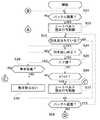
図3に戻り、次に、直流モータ10の端子間電圧よりシートベルトが引き出されているか否かを判別し(ステップS33)、シートベルトが引き出されていない場合には、後述するステップS38に進む一方、シートベルトが引き出されている場合には、直流モータ10の端子間電圧よりシートベルトの引き出しが停止したか否かを判別する(ステップS34)。シートベルトの引き出しが停止していない場合には、該判別を繰り返す一方、シートベルトの引き出しが停止している場合には、ドア開閉検出部19からの制御信号によりドアが開いているのか閉じているのか判別する(ステップS35)。
【0040】
ドアが閉じている場合には、自車両の車速vが所定値v1(例えば、10km/h)より大きいか否かを判別し(ステップS36)、自車両の車速vが所定値v1より大きい場合には、ステップS32と同様にシートベルト弛み付与制御を行い(ステップS37)、シートベルトのタングがバックルに装着されたことをバックル接続有無検出部16により検出されたか否かを判別する(ステップS38)。
【0041】
上記ステップS35で、ドアが開いている場合には、車両後進検出部17からの制御信号により自車両が後進しているか否かを判別し(ステップS39)、自車両が後進していない場合には、ステップS37に進む。これにより、例えば、車両の停止中にドアを開けて、荷物を固定するためにシートベルトを引き出し装着した場合に、シートベルトが巻き取られるので、シートベルトがドアに挟まれて傷つけることがなくなる。
【0042】
一方、ステップS39で、自車両が後進している場合には、MPU14からPWM信号を直流モータ駆動部11に入力することにより、直流モータ10を回転させない、即ち、シートベルトを巻き取らないようにして(ステップS40)、ステップS38に進む。これにより、例えば乗員がドアを開いた状態で、駐車のために車両を後進させるときにシートベルトの巻き取りが行われず、乗員に違和感を与えることがなくなり、快適なシートベルト装着環境を提供することができる。
【0043】
上記ステップS36で、自車両の車速vが所定値v1以下の場合には、ステップS40に進む。これにより、例えば、乗員が車両を一旦停止させ、左右の確認のために前のめりになり、シートベルトが引き出された場合に、シートベルトの巻き取りが行われないので、確認中の乗員に違和感を与えず確認の邪魔をしないようにすることができる。
【0044】
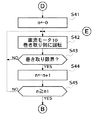
上記ステップS38で、バックル接続有無検出部16によりシートベルトのタングがバックルに装着されたことが検出された場合には、ステップS33に戻る一方、バックル接続有無検出部16によりシートベルトのタングがバックルに装着されたことを検出されない場合には、シートベルトを限界まで巻き取る回数をカウントするカウンタnの値をリセットし(n←0)(ステップS41)、MPU14からPWM信号を直流モータ駆動部11に入力することにより、直流モータ10をシートベルトの巻き取り側に回転させ(ステップS42)、直流モータ10に流れる電流よりシートベルトが巻き取り限界であるか否かを判別する(ステップS43)。これにより、シートベルトの不適正な弛みを一旦完全に除去する。
【0045】
ステップS43で、シートベルトが巻き取り限界でない場合には、ステップS42に戻る一方、シートベルトが巻き取り限界である場合には、カウンタnの値を1インクリメントし(n←n+1)(ステップS44)、カウンタnの値が所定値n1(例えば、3回)以上であるか否かを判別する(ステップS45)。ここで、カウンタnの値が所定値n1(例えば、3回)以上であるか否かの判別、即ち、シートベルトを限界まで巻き取る回数が例えば、3回以上であるか否かの判別を行うのは、シートベルトの格納途中で、シートベルトが乗員の腕などに掛かり、格納が止められた時を考慮したためである。
【0046】
上記ステップS45で、カウンタnの値が所定値n1未満である場合は、ステップS42に戻る一方、カウンタnの値が所定値n1以上である場合は、ステップS31に戻る。
【0047】
上記ステップS31に戻り、バックル接続有無検出部16によりシートベルトのタングがバックルに装着されたことが検出されない場合には、直流モータ10の端子間電圧よりシートベルトが引き出されているか否かを判別し(ステップS50)、シートベルトが引き出されていない場合には、ステップS31に戻る一方、シートベルトが引き出されている場合には、直流モータ10の端子間電圧よりシートベルトの引き出しが停止したか否かを判別する(ステップS51)。シートベルトの引き出しが停止していない場合には、該判別を繰り返す一方、シートベルトの引き出しが停止している場合には、ドア開閉検出部19からの制御信号によりドアが開いているのか閉じているのか判別する(ステップS52)。
【0048】
ドアが開いている場合には、シートベルト格納前の猶予時間として所定時間t2(例えば1s)ウエイトし(ステップS53)、カウンタnの値をリセットして(n←0)(ステップS55)、上記ステップS42に進む。一方、ドアが閉じている場合には、シートベルト格納前の猶予時間として所定時間t3(例えば5s)ウエイトし(ステップS54)、上記ステップS55に進む。尚、所定時間t2は所定時間t3より短時間である。これにより、例えば乗員がシートベルトを装着するつもりがなく引き出して、すぐに車外に出てドアを閉めるような場合でも、シートベルトの格納ができ、シートベルトがドアに挟まれて傷つけることがなくなり、シートベルトの破損を防止することができる。
【0049】
上述したように、本実施の形態によれば、ステップS52でドアが開いているのか閉じているのか判別し、ドアが開いている場合は、ドアが閉じている場合に比べ、シートベルト格納前の猶予時間が短いので(ステップS53、ステップS54)、シートベルトの引き出し停止から巻き取り終了までにかかる時間を短くでき、シートベルトがドアに挟まれて傷つけることがなくなり、シートベルトの破損を防止することができる。
【0050】
尚、本実施の形態では、ステップS52でドアが開いているのか閉じているのか判別し、この判別結果に応じてシートベルト格納前の猶予時間を決めたが、該判別結果に応じてシートベルトの巻き取り速度、シートベルト巻き取り力又はシートベルト巻き取り開始から巻き取り終了までの時間間隔を変えてもよい。この場合は、ドアが開いているときに、シートベルトの巻き取り速度を速くする、シートベルトの巻き取り力を大きくする又はシートベルト巻き取り開始から巻き取り終了までの時間間隔を短くする。
【0051】
これにより、シートベルトの引き出し停止から巻き取り終了までにかかる時間を短くでき、シートベルトがドアに挟まれて傷つけることがなくなり、シートベルトの破損を防止することができる。
【0052】
【発明の効果】
以上詳細に説明したように、請求項1の車両用乗員拘束保護装置によれば、ドアが開いていることが検出されたときは、ドアが閉じているときに比べ、シートベルトの格納が速く行われるようにモータの駆動が制御されるので、シートベルトがドアに挟まれることがなくなり、シートベルトの破損を防止することができる。
【図面の簡単な説明】
【図1】本実施の形態に係る車両用乗員拘束保護装置が備えている電動リトラクタ100の構成を示す図である。
【図2】直流モータ駆動部11の回路図である。
【図3】MPU14が実行する制御プログラムの一例を示したフローチャートである。
【図4】MPU14が実行する制御プログラムの一例を示したフローチャートである。
【図5】MPU14が実行する制御プログラムの一例を示したフローチャートである。
【図6】シートベルト弛み付与制御の一例を示すフローチャートである。
【符号の説明】
1 フレーム
2 シートベルトロック機構
3 リールシャフト
5 リールシャフト用プーリ
6 直流モータ用プーリ
7 動力伝達ベルト
10 直流モータ
11 直流モータ駆動部
14 MPU(制御手段)
16 バックル接続有無検出部(シートベルト装着検出手段)
17 車両後進検出部(車両後進検出手段)
18 車速検出部(車両速度検出手段)
19 ドア開閉検出部(ドア開閉検出手段)
100 電動リトラクタ
*+[0001]
BACKGROUND OF THE INVENTION
The present invention relates to a vehicle occupant restraint protection device installed in a vehicle such as an automobile, and more particularly to a vehicle occupant restraint protection device using an electric retractor that winds and pulls out a seat belt for protecting the occupant.
[0002]
[Prior art]
A vehicle occupant restraint protection device using an electric retractor that winds and pulls out a seat belt for protecting the occupant has been known.
[0003]
In the vehicle occupant restraint protection device, when the seat belt is not attached, the occupant pulls out the seat belt in an attempt to put on the seat belt, and then stops taking out the seat belt if the clerk does not easily enter the buckle. Therefore, for example, assuming a time required for this trouble, a predetermined time is taken, and then the seat belt is stored.
[0004]
In addition, when the seat belt is worn, for example, when the occupant temporarily stops the vehicle and confirms left and right, the seat belt is turned forward, and when the seat belt is pulled out, the occupant who is confirming does not feel uncomfortable and does not disturb the confirmation. In order to prevent this, the seat belt is not retracted while being pulled out, and then the vehicle starts running and the seat belt is retracted when the vehicle speed exceeds a predetermined speed.
[0005]
[Problems to be solved by the invention]
However, in the former of the above-mentioned vehicle occupant restraint protection device, when the seat belt is not attached, for example, when the occupant pulls out without intending to attach the seat belt and immediately goes out of the vehicle and closes the door, Since the seat belt cannot be stored in a short time, the seat belt may be caught between the doors and may be damaged.
[0006]
In the latter of the above vehicle occupant restraint protection devices, when the vehicle is stopped, for example, when a seat belt is pulled out and attached to fix the luggage (with the seat belt attached), and the door is closed in that state. If there is any unnecessary slack in the seat belt, the seat belt may be pinched by the door and damage the seat belt.
[0007]
The present invention has been made paying attention to the above points, and an object thereof is to provide a vehicle occupant restraint protection device for a vehicle that can prevent a seat belt from being damaged.
[0008]
[Means for Solving the Problems]
In order to achieve the above object, a vehicle occupant restraint protection device according to
[0009]
According to the configuration of the present invention, when it is detected that the door is open, the drive of the motor is controlled so that the seat belt is retracted faster than when the door is closed. The belt is not pinched by the door, and the seat belt can be prevented from being damaged.
[0010]
The control means may control at least one of a rotational speed and a rotational force of the motor. That is, the vehicle occupant restraint protection device according to
[0011]
According to this configuration, the drive of the motor is controlled so that the seat belt is retracted quickly based on at least one of increasing the rotational speed of the motor and increasing the rotational force of the motor. The seat belt can be prevented from being damaged.
[0018]
DETAILED DESCRIPTION OF THE INVENTION
Hereinafter, embodiments of the present invention will be described with reference to the drawings.
[0019]
FIG. 1 is a diagram illustrating a configuration of an
[0020]
The
[0021]
Next, the
[0022]
A predetermined number of external teeth are formed on the outer periphery of each of the
[0023]
The central axis of the
[0024]
The
[0025]
For example, Hitachi HD64333337YF is used as the MPU 14, and DME44SA manufactured by Japan Servo, for example, is used as the
[0026]
FIG. 2 is a circuit diagram of the DC
[0027]
A circuit C1 in FIG. 2 is a current detection circuit that detects a current i flowing through the
[0028]
The circuit C2 is a voltage measurement circuit that measures the voltage across the terminal applied to the
[0029]
IF1 to IF4 have a low-pass filter configuration including, for example, a resistor r2, a resistor r3 having a resistance value smaller than the resistor r2, and a capacitor c3, and a cutoff frequency is set to 20 Hz, for example. As a result, the influence of the PWM signal output to the
[0030]
Returning to FIG. 1, the
[0031]
The buckle connection presence /
[0032]
The
[0033]
3 to 5 are flowcharts illustrating an example of a control program executed by the
[0034]
First, it is determined whether the buckle connection presence /
[0035]
FIG. 6 is a flowchart showing an example of seat belt slack imparting control.
[0036]
First, by inputting a PWM signal from the
[0037]
If the seat belt is not at the take-up limit in step S322, the process returns to step S321. If the seat belt is at the take-up limit, the PWM signal is input from the
[0038]
If the predetermined time t1 has not elapsed in step S324, the process returns to step S323, while if the predetermined time t1 has elapsed, the withdrawal of the seat belt by the
[0039]
Returning to FIG. 3, next, it is determined whether or not the seat belt is pulled out from the voltage between the terminals of the DC motor 10 (step S33). If the seat belt is not pulled out, the process proceeds to step S38 to be described later. On the other hand, if the seat belt is being pulled out, it is determined whether or not the seat belt has been pulled out based on the voltage across the terminals of the DC motor 10 (step S34). If the withdrawal of the seat belt is not stopped, the determination is repeated. On the other hand, if the withdrawal of the seat belt is stopped, the control signal from the door open /
[0040]
When the door is closed, it is determined whether or not the vehicle speed v of the host vehicle is greater than a predetermined value v1 (for example, 10 km / h) (step S36), and the vehicle speed v of the host vehicle is greater than the predetermined value v1. In the same manner as in step S32, seat belt slack imparting control is performed (step S37), and it is determined whether or not the buckle connection presence /
[0041]
If the door is open in step S35, it is determined whether or not the host vehicle is moving backward by a control signal from the vehicle reverse detection unit 17 (step S39), and the host vehicle is not moving backward. Advances to step S37. Thus, for example, when the door is opened while the vehicle is stopped and the seat belt is pulled out and fixed to fix the luggage, the seat belt is wound up, so that the seat belt is not caught and damaged by the door. .
[0042]
On the other hand, when the host vehicle is moving backward in step S39, the
[0043]
If the vehicle speed v of the host vehicle is equal to or less than the predetermined value v1 in step S36, the process proceeds to step S40. As a result, for example, when the occupant temporarily stops the vehicle, turns forward to check left and right, and the seat belt is pulled out, the seat belt is not taken up. It is possible to avoid disturbing the confirmation without giving it.
[0044]
If the buckle connection presence /
[0045]
If the seat belt is not at the take-up limit in step S43, the process returns to step S42. If the seat belt is at the take-up limit, the value of the counter n is incremented by 1 (n ← n + 1) (step S44). Then, it is determined whether or not the value of the counter n is greater than or equal to a predetermined value n1 (for example, 3 times) (step S45). Here, it is determined whether or not the value of the counter n is a predetermined value n1 (for example, 3 times) or more, that is, whether or not the number of times the seat belt is wound up to the limit is, for example, 3 or more. This is because the seat belt is caught on the occupant's arm or the like during the storage of the seat belt and the storage is stopped.
[0046]
If the value of the counter n is less than the predetermined value n1 in step S45, the process returns to step S42, whereas if the value of the counter n is greater than or equal to the predetermined value n1, the process returns to step S31.
[0047]
Returning to step S31, if the buckle connection presence /
[0048]
When the door is open, a predetermined time t2 (for example, 1 s) is waited as a grace time before storing the seat belt (step S53), the value of the counter n is reset (n ← 0) (step S55), Proceed to step S42. On the other hand, when the door is closed, a waiting time t3 (for example, 5 seconds) is waited as a grace time before storing the seat belt (step S54), and the process proceeds to step S55. The predetermined time t2 is shorter than the predetermined time t3. For example, even if the passenger pulls out without intending to wear the seat belt, and then immediately goes out of the vehicle and closes the door, the seat belt can be stored and the seat belt is not caught by the door and is not damaged. The seat belt can be prevented from being damaged.
[0049]
As described above, according to the present embodiment, it is determined in step S52 whether the door is open or closed. When the door is open, the seatbelt is stored before the door is closed. Since the grace time is short (steps S53 and S54), the time taken from the stoppage of the seatbelt to the end of the winding can be shortened, the seatbelt is not pinched by the door, and the seatbelt is prevented from being damaged. can do.
[0050]
In this embodiment, it is determined whether the door is open or closed in step S52, and the grace time before the seat belt is stored is determined according to the determination result, but the seat belt is determined according to the determination result. The winding speed, the seat belt winding force, or the time interval from the start of seat belt winding to the end of winding may be changed. In this case, when the door is open, the seat belt retracting speed is increased, the seat belt retracting force is increased, or the time interval from the start of the seat belt retracting to the end of the retracting is shortened.
[0051]
As a result, it is possible to shorten the time taken from the stop of the seat belt pulling out to the end of the winding, and the seat belt is not pinched by the door and is not damaged, so that the seat belt can be prevented from being damaged.
[0052]
【The invention's effect】
As described above in detail, according to the vehicle occupant restraint protection device of
[Brief description of the drawings]
FIG. 1 is a diagram showing a configuration of an
FIG. 2 is a circuit diagram of a DC
FIG. 3 is a flowchart showing an example of a control program executed by the
FIG. 4 is a flowchart showing an example of a control program executed by the
FIG. 5 is a flowchart showing an example of a control program executed by the
FIG. 6 is a flowchart illustrating an example of seat belt slack imparting control.
[Explanation of symbols]
DESCRIPTION OF
16 Buckle connection presence / absence detection unit (seat belt wearing detection means)
17 Vehicle reverse detection unit (vehicle reverse detection means)
18 Vehicle speed detection unit (vehicle speed detection means)
19 Door open / close detection unit (door open / close detection means)
100 electric retractor
* +
Claims (3)
前記モータの駆動を制御する制御手段(MPU)と、
前記シートベルトのタングがバックルに装着されたか否かを検出するバックル接続有無検出部と、
ドアの開閉を検出するドア開閉検出手段とを備え、
前記制御手段(MPU)は、前記シートベルトが引き出されている状態で、前記バックル接続有無検出部によりバックルの非装着が検出されたときには、前記シートベルトの巻き取りを行い、前記シートベルトが引き出されている状態と前記バックルの非装着の検出に加えて前記ドア開閉検出手段によりドアが開いていることが検出されたときは、前記ドアが閉じているときに比べ、前記シートベルトの格納が速く行われるように前記モータの駆動を制御することを特徴とする車両用乗員拘束保護装置。In a vehicle occupant restraint protection device that retracts a seat belt by driving a motor
Control means (MPU) for controlling the driving of the motor;
A buckle connection presence / absence detecting unit for detecting whether or not the tongue of the seat belt is attached to the buckle ;
And a door opening and closing detection means for detecting the opening and closing of the door,
The control means (MPU) winds up the seat belt when the seat belt is pulled out and detects that the buckle is not attached by the buckle connection presence / absence detecting unit, and the seat belt is pulled out. When the door opening / closing detection means detects that the door is open , in addition to the detection of whether the buckle is not attached, and when the door is closed, the seat belt is retracted compared to when the door is closed. fast vehicle occupant restraint protection device comprising a benzalkonium control the drive of the motor to occur.
Priority Applications (16)
| Application Number | Priority Date | Filing Date | Title |
|---|---|---|---|
| JP23160598A JP4077946B2 (en) | 1998-08-18 | 1998-08-18 | Vehicle occupant restraint protection device |
| GB0205911A GB2370538B (en) | 1997-12-16 | 1998-12-16 | Automotive passenger restraint and protection apparatus and seatbelt protraction and retraction amount-detecting device |
| GB0205937A GB2370541B (en) | 1997-12-16 | 1998-12-16 | Automotive passenger restraint and protection apparatus and seatbelt protraction and retraction amount-detecting device |
| GB0205945A GB2370543B (en) | 1997-12-16 | 1998-12-16 | Automative passenger restraint and protection apparatus and seatbelt protraction and retraction amount-detecting device |
| GB9827725A GB2335890B (en) | 1997-12-16 | 1998-12-16 | Automotive passenger restraint and protection apparatus and seatbelt protraction and retraction amount detecting device |
| GB0205908A GB2370536B (en) | 1997-12-16 | 1998-12-16 | Automotive passenger restraint and protection apparatus and seatbelt protraction and retraction amount-detecting device |
| GB0211665A GB2370544B (en) | 1997-12-16 | 1998-12-16 | Automotive passenger restraint and protection apparatus and seatbelt protraction and retraction amount-detecting device |
| GB0205916A GB2370539B (en) | 1997-12-16 | 1998-12-16 | Automotive passenger restraint and protection apparatus and seatbelt protraction and retraction amount-detecting device |
| GB0205917A GB2370540B (en) | 1997-12-16 | 1998-12-16 | Automotive passenger restraint and protection apparatus and seatbelt protraction and retraction amount-detecting device |
| GB0211669A GB2370545B (en) | 1997-12-16 | 1998-12-16 | Automotive passenger restraint and protection apparatus and seatbelt protraction and retraction amount-detecting device |
| GB0205939A GB2370542B (en) | 1997-12-16 | 1998-12-16 | Automotive passenger restraint and protection apparatus and seatbelt protraction and retraction amount-detecting device |
| GB0205909A GB2370537B (en) | 1997-12-16 | 1998-12-16 | Automotive passenger restraint and protection apparatus and seatbelt protraction and retraction amount-detecting device |
| US09/578,464 US6485057B1 (en) | 1997-12-16 | 2000-05-25 | Automotive passenger restraint and protection apparatus and seatbelt protraction and retraction amount-detecting device |
| US10/247,208 US6729650B2 (en) | 1997-12-16 | 2002-09-18 | Automotive passenger restraint and protection apparatus and seatbelt protraction and retraction amount-detecting device |
| US10/717,054 US6997474B2 (en) | 1997-12-16 | 2003-11-19 | Automotive passenger restraint and protection apparatus and seatbelt protraction and retraction amount-detecting device |
| US11/060,187 US7040444B2 (en) | 1997-12-16 | 2005-02-17 | Automotive passenger restraint and protection apparatus |
Applications Claiming Priority (1)
| Application Number | Priority Date | Filing Date | Title |
|---|---|---|---|
| JP23160598A JP4077946B2 (en) | 1998-08-18 | 1998-08-18 | Vehicle occupant restraint protection device |
Publications (3)
| Publication Number | Publication Date |
|---|---|
| JP2000052926A JP2000052926A (en) | 2000-02-22 |
| JP2000052926A5 JP2000052926A5 (en) | 2005-10-27 |
| JP4077946B2 true JP4077946B2 (en) | 2008-04-23 |
Family
ID=16926141
Family Applications (1)
| Application Number | Title | Priority Date | Filing Date |
|---|---|---|---|
| JP23160598A Expired - Lifetime JP4077946B2 (en) | 1997-12-16 | 1998-08-18 | Vehicle occupant restraint protection device |
Country Status (1)
| Country | Link |
|---|---|
| JP (1) | JP4077946B2 (en) |
Families Citing this family (7)
| Publication number | Priority date | Publication date | Assignee | Title |
|---|---|---|---|---|
| JP2006321358A (en) | 2005-05-19 | 2006-11-30 | Takata Corp | Seat belt retractor, seat belt device, and vehicle with seat belt device |
| JP4714513B2 (en) * | 2005-06-28 | 2011-06-29 | タカタ株式会社 | Seat belt retractor, seat belt device, vehicle with seat belt device |
| JP2007001534A (en) | 2005-06-27 | 2007-01-11 | Takata Corp | Seat belt retractor, seat belt device and vehicle with seat belt device |
| JP4760182B2 (en) * | 2005-07-20 | 2011-08-31 | 日産自動車株式会社 | Seat belt control device |
| JP2007112267A (en) * | 2005-10-19 | 2007-05-10 | Takata Corp | Seat belt retractor, seat belt device, and vehicle equipped with seat belt device |
| JP2007145079A (en) * | 2005-11-24 | 2007-06-14 | Takata Corp | Seat belt retractor, seat belt device, and vehicle with seat belt device |
| JP4889605B2 (en) * | 2007-09-25 | 2012-03-07 | 本田技研工業株式会社 | Vehicle seat belt device |
-
1998
- 1998-08-18 JP JP23160598A patent/JP4077946B2/en not_active Expired - Lifetime
Also Published As
| Publication number | Publication date |
|---|---|
| JP2000052926A (en) | 2000-02-22 |
Similar Documents
| Publication | Publication Date | Title |
|---|---|---|
| US4655312A (en) | Electrically adjusted safety restraint system | |
| EP1369320B1 (en) | Failure diagnostic system for seat belt retractor | |
| JP4077946B2 (en) | Vehicle occupant restraint protection device | |
| US20130162002A1 (en) | Occupant protection device | |
| US7836995B2 (en) | Failure diagnosis method of seat belt system and seat belt system having failure diagnosis function | |
| US20100117438A1 (en) | Seatbelt device | |
| JP2007253937A (en) | Motor drive seat belt device | |
| JP3695622B2 (en) | Vehicle occupant restraint protection device | |
| JP3761717B2 (en) | Vehicle occupant restraint protection device | |
| JP3830667B2 (en) | Vehicle occupant restraint protection device | |
| JP3819151B2 (en) | Vehicle occupant restraint protection device | |
| JP4077942B2 (en) | Vehicle occupant restraint protection device | |
| JP4011748B2 (en) | Vehicle occupant restraint protection device | |
| JP3554484B2 (en) | Vehicle occupant restraint system | |
| JP3695621B2 (en) | Vehicle occupant restraint protection device | |
| JP4011749B2 (en) | Vehicle occupant restraint protection device | |
| JP4052491B2 (en) | Vehicle occupant restraint protection device | |
| JP4226098B2 (en) | Vehicle occupant restraint protection device | |
| JP3828264B2 (en) | Vehicle occupant restraint protection device | |
| JPH11192926A (en) | Occupant constraint and protective device for vehicle | |
| JP3730012B2 (en) | Vehicle occupant restraint protection device | |
| JP5236510B2 (en) | Vehicle seat belt device | |
| JP3762118B2 (en) | Vehicle occupant restraint protection device | |
| JP3734369B2 (en) | Seat belt pull-up amount detection device | |
| JP3795230B2 (en) | Vehicle occupant restraint protection device |
Legal Events
| Date | Code | Title | Description |
|---|---|---|---|
| A521 | Written amendment |
Free format text: JAPANESE INTERMEDIATE CODE: A523 Effective date: 20050722 |
|
| A621 | Written request for application examination |
Free format text: JAPANESE INTERMEDIATE CODE: A621 Effective date: 20050722 |
|
| RD03 | Notification of appointment of power of attorney |
Free format text: JAPANESE INTERMEDIATE CODE: A7423 Effective date: 20060509 |
|
| A711 | Notification of change in applicant |
Free format text: JAPANESE INTERMEDIATE CODE: A712 Effective date: 20070420 |
|
| A521 | Written amendment |
Free format text: JAPANESE INTERMEDIATE CODE: A523 Effective date: 20070807 |
|
| A977 | Report on retrieval |
Free format text: JAPANESE INTERMEDIATE CODE: A971007 Effective date: 20070903 |
|
| A131 | Notification of reasons for refusal |
Free format text: JAPANESE INTERMEDIATE CODE: A131 Effective date: 20070913 |
|
| A521 | Written amendment |
Free format text: JAPANESE INTERMEDIATE CODE: A523 Effective date: 20071105 |
|
| TRDD | Decision of grant or rejection written | ||
| A01 | Written decision to grant a patent or to grant a registration (utility model) |
Free format text: JAPANESE INTERMEDIATE CODE: A01 Effective date: 20071130 |
|
| R155 | Notification before disposition of declining of application |
Free format text: JAPANESE INTERMEDIATE CODE: R155 |
|
| A61 | First payment of annual fees (during grant procedure) |
Free format text: JAPANESE INTERMEDIATE CODE: A61 Effective date: 20080204 |
|
| R150 | Certificate of patent or registration of utility model |
Free format text: JAPANESE INTERMEDIATE CODE: R150 |
|
| FPAY | Renewal fee payment (event date is renewal date of database) |
Free format text: PAYMENT UNTIL: 20110208 Year of fee payment: 3 |
|
| FPAY | Renewal fee payment (event date is renewal date of database) |
Free format text: PAYMENT UNTIL: 20120208 Year of fee payment: 4 |
|
| FPAY | Renewal fee payment (event date is renewal date of database) |
Free format text: PAYMENT UNTIL: 20130208 Year of fee payment: 5 |
|
| FPAY | Renewal fee payment (event date is renewal date of database) |
Free format text: PAYMENT UNTIL: 20140208 Year of fee payment: 6 |
|
| R250 | Receipt of annual fees |
Free format text: JAPANESE INTERMEDIATE CODE: R250 |
|
| R250 | Receipt of annual fees |
Free format text: JAPANESE INTERMEDIATE CODE: R250 |
|
| R250 | Receipt of annual fees |
Free format text: JAPANESE INTERMEDIATE CODE: R250 |
|
| R250 | Receipt of annual fees |
Free format text: JAPANESE INTERMEDIATE CODE: R250 |
|
| R250 | Receipt of annual fees |
Free format text: JAPANESE INTERMEDIATE CODE: R250 |
|
| EXPY | Cancellation because of completion of term |