JP4077923B2 - Vibration type actuator - Google Patents
Vibration type actuator Download PDFInfo
- Publication number
- JP4077923B2 JP4077923B2 JP07470098A JP7470098A JP4077923B2 JP 4077923 B2 JP4077923 B2 JP 4077923B2 JP 07470098 A JP07470098 A JP 07470098A JP 7470098 A JP7470098 A JP 7470098A JP 4077923 B2 JP4077923 B2 JP 4077923B2
- Authority
- JP
- Japan
- Prior art keywords
- vibration
- piezoelectric element
- elastic body
- axis
- vibrating body
- Prior art date
- Legal status (The legal status is an assumption and is not a legal conclusion. Google has not performed a legal analysis and makes no representation as to the accuracy of the status listed.)
- Expired - Fee Related
Links
Images


Classifications
-
- H—ELECTRICITY
- H10—SEMICONDUCTOR DEVICES; ELECTRIC SOLID-STATE DEVICES NOT OTHERWISE PROVIDED FOR
- H10N—ELECTRIC SOLID-STATE DEVICES NOT OTHERWISE PROVIDED FOR
- H10N30/00—Piezoelectric or electrostrictive devices
- H10N30/20—Piezoelectric or electrostrictive devices with electrical input and mechanical output, e.g. functioning as actuators or vibrators
- H10N30/202—Piezoelectric or electrostrictive devices with electrical input and mechanical output, e.g. functioning as actuators or vibrators using longitudinal or thickness displacement combined with bending, shear or torsion displacement
Description
【0001】
【発明の属する技術分野】
本発明は、振動型アクチュエータおよび振動型駆動装置に関する。
【0002】
【従来の技術】
多軸周りの運動を生成する振動型アクチュエータとして、例えば精密工学会誌(Vol.61,No.3,pp.1227−1230,1995)、あるいは日経メカニカル(No.5,pp.26−27,1997.4.28)に開示の球面振動型アクチュエータが提案されている。
【0003】
この球面振動型アクチュエータは、球形形状に形成されたものを移動体とし、この球状の移動体(ロータ)を直交する3軸のうちの2軸あるいは3軸の回りに回転させるようにしたものであって、1軸回りについて回転力を振動(例えば進行波)により生成する振動体(ステータ)を前記移動体に加圧接触するように複数配置するように構成されている。
【0004】
このような球面振動型アクチュエータとしては、現在は4個の振動体を用いた2自由度タイプと、3個の振動体を用いた3自由度タイプが開発されている。
【0005】
また、球面振動型アクチュエータに用いられている前記振動体としては、例えばカメラのオートフォーカスレンズの駆動等に用いられているリング型振動型アクチュエータの振動体と同様のもので、図16にその外観形状を示す。この振動体19は、リング形状の弾性体19aの底面部に圧電性セラミックスで形成された圧電素子19bを接着したもので、圧電素子19bには適当な位相差(半波長の奇数倍の位相差)で2相の駆動相が形成されていて、この両駆動相に適当な位相差(例えば90°)を有する交番信号を印加することで、弾性体19aに周方向に沿ってたわみ(曲げ)進行波が形成される。そして、この弾性体19aに不図示の接触体を不図示の加圧手段を介して接触させることで、前記接触体と前記振動体19は進行波の進行方向と逆方向を移動方向として相対移動する。なお、振動体19を固定とした場合、前記接触体は移動体として例えば回転する。
【0006】
球面振動型アクチュエータ、例えば2自由度タイプの球面振動型アクチュエータは、図17に示すように、対向の一対の振動体19を球状の移動体2の周囲に2対配置することで、振動体19の中心を回転軸として2自由度の移動を実現している。
【0007】
また、他の多軸周りの運動を生成する振動型アクチュエータとしては、Third International Conference on Motion and Vibration Control,Chiba,、September,1−6、1996、pp.K9−K15に記載されている圧電マニピュレータが提案されている。その構成を図18に示す。
【0008】
この圧電マニピュレータは、円筒状の弾性体と圧電素子で形成された振動体19と、振動体19の軸方向の端部に配置された半球状の移動体20a、20bから構成され、前記振動体19の周囲には分割された不図示の電極が形成されている。また、半球状の移動体20aと20bとは振動体19内に配置されたバネ21で互いに引き合うことで、振動体19の開口端に移動体20aと20bとがそれぞれ常に接するようにしている。
【0009】
そして、振動体19に励起する振動を調整するように、分割された電極のそれぞれに適当な交流電圧を加えることによって、振動体19の開口端にそれぞれ接する2つの半球状の移動体20a、20bを1つの移動体19のみで駆動するようにしている。
【0010】
この駆動原理は、半球状の移動体20a、20bと振動体19との接触点に楕円運動を生成するものであり、各電極に印加する交流電圧を変化させることで、複数面内の楕円運動が生成され、半球状の回転子を任意の方向に駆動できるようにしたものである。
【0011】
【発明が解決しようとする課題】
しかしながら、図17に示す従来の球面振動型アクチュエータは、複数の振動体を用いているため、以下のような難点が指摘されている。
【0012】
▲1▼:1つの軸周りの回転に対して、複数の振動体を用いるために、各振動体の特性を一致させる必要がある。
【0013】
▲2▼:移動体の周囲に複数の振動体が存在するため、小型化が難しくスペース効率が悪い。
【0014】
▲3▼:駆動に供しない他の軸回り用の振動体が移動体に圧接されているため、回転に対する抵抗となり、効率や発熱の問題がある。
【0015】
また、図18に示す従来の筒状振動体の振動型アクチュエータについては、以下のような難点が指摘されている。
【0016】
▲1▼:振動体の周面に設けられた複数の電極に駆動方向に合わせて交番信号を入力するため、入力する信号が各電極毎に異なるため、複雑な制御を要する。
【0017】
▲2▼:円筒形状の振動体19に対して半球状の移動体20a、20bを振動体19内に配置されたバネ21を互いに引き合わせて圧接しているため、可動域が制限され、また圧接の加圧力が一定でなく、加圧力の調整を簡単にできない。
【0020】
【課題を解決するための手段】
本発明である振動型アクチュエータは、板状の弾性体上に柱状の弾性体が接合された振動体と、柱状の弾性体に接触する接触体と、柱状の弾性体に設けられ、柱状の弾性体の長手方向と直交する面内において互いに直交する2方向に変位する振動を、柱状の弾性体に発生させるための第1の電気−機械エネルギー変換素子と、板状の弾性体に設けられ、板状の弾性体を屈曲させて、板状の弾性体に上記2方向と直交する方向に変位する振動を発生させるための第2の電気−機械エネルギー変換素子とを有する。ここで、柱状の弾性体と板状の弾性体に発生させた3つの変位のうち、少なくとも2方向の変位を選択的に組み合わせた合成振動を用いて、柱状の弾性体における接触体との接触部に、任意の方向の円または楕円運動を形成する。
【0040】
【発明の実施の形態】
(第1の実施の形態)
図1は本発明の第1の実施の形態を示す。
【0041】
図1は本実施の形態の振動型アクチュエータの駆動原理を示し、単一の振動体としての円柱形状の弾性体1間に、図1の(b),(c),(d)に夫々示す変位を与える電気−機械エネルギー変換素子としての圧電素子3が挟持固定されている。また、圧電素子としては、例えば単板の圧電素子板を複数枚重ね合わせ、必要に応じて圧電素子板の間に電極板を挟み込むようにして、必要とする圧電素子板に対して個々に駆動のための交番信号を印加できるようにしている。
【0042】
本実施の形態において、圧電素子3は、交番信号の印加により軸方向に伸縮変位を繰り返し、図1の(b)に示すように、互いに直交するx,y,zの3軸の内、z軸方向の変位である縦方向の振動としての縦振動を励起する第1の圧電素子と、図1の(c)に示すように、z−x平面内で横方向の振動としての横(曲げ)振動を励起する第2の圧電素子と、図1の(d)に示すように、z−y平面内で横方向の振動としての横(曲げ)振動を励起する第3の圧電素子を有している。上記の第1の圧電素子は、厚さ方向に一様に分極されている。また、第2、第3の圧電素子は、直径を挟んだ両側の部分で、厚さ方向に互いに逆極性を持つように分極されている。
【0043】
ここで、前記第2の圧電素子と前記第3の圧電素子に対して例えば位相が90°異なる交番信号を印加すると、振動体に対する2つの曲げ振動の合成で、振動体の表面上にはz軸回り(x−y平面内)の楕円運動が形成される。この場合、x軸とy軸についての振動体の固有振動数は略一致するため、この固有振動数を駆動周波数とする交番信号を前記第2の圧電素子と前記第3の圧電素子に印加すれば上記した楕円振動が生成されることになる。
【0044】
次に、前記第1の圧電素子に前記振動体のz軸方向における固有振動数と略一致する周波数の交番信号を印加すると、前記振動体は一定の周期で1次モードで縦振動を繰り返すことになる。
【0045】
その際、前記振動体が振動する縦振動の振動の1周期と一致(略一致)した1周期の振動で励振するように前記第2の圧電素子に交番信号を印加すると、前記振動体の表面上の点にはx−z平面内の楕円運動が生成され、x軸方向(y軸回り)への駆動力が得られる。この場合、前記振動体のz軸方向における固有振動数とx−z平面における曲げ振動の1次モードの固有振動数は異なるため、図1の(c)に示すように、本実施の形態ではx軸方向の曲げ振動に対する固有振動数の2次モードで前記第2の圧電素子を駆動し、縦振動の周期と曲げ振動の周期とを一致させるようにしている。
【0046】
同様にして、前記振動体が振動する縦振動の振動の1周期と一致(略一致)した1周期の振動で励振するように前記第3の圧電素子に交番信号を印加すると、前記振動体の表面上の点にはy−z平面内の楕円運動が生成され、y軸方向(x軸回り)への駆動力が得られる。この場合、前記振動体のz軸方向における固有振動数とy−z平面における曲げ振動の固有振動数は異なるため、図1の(d)に示すように、本実施の形態ではy軸方向の曲げ振動に対する固有振動数の2次モードで前記第3の圧電素子を駆動することにより、縦振動の周期と曲げ振動の周期とを一致させるようにしている。
【0047】
すなわち、振動体1の固有振動数に近い周波数の交番信号、例えば交流電圧を第1の圧電素子、第2の圧電素子および第3の圧電素子に印加することにより、振動体に図1の(b)、(c)、(d)のような固有振動の縦振動あるいは横(曲げ)振動が励振される。
【0048】
そして、前記第1の圧電素子、第2の圧電素子及び第3の圧電素子の内のいずれか2つに選択的に交番信号を印加することにより、振動体1の縦振動と、互いに直交する方向の横(曲げ)振動の2つが組み合わさって、振動体1の表面上の点に楕円運動が生成される。例えば、(b)と(c)の組み合わせによってx−z面内の楕円運動が生成される。あるいは(b)と(d)の組み合わせによってy−z平面内の楕円運動が、(c)と(d)の組み合わせによってx−y平面内の楕円運動が生成される。
【0049】
従って、振動体のある一部に移動体を圧接すると、移動体を複数の方向に駆動することができる。
【0050】
従来の圧電型アクチュエータの駆動原理は、振動体を構成する圧電素子の2相の駆動相に位相のずれた交番信号を印加することで弾性体の表面の点について1軸回りの楕円運動を形成するようにしていたが、本実施の形態では、3相の圧電素子(第1の圧電素子、第2の圧電素子、第3の圧電素子)を組み合わせることにより、3軸回り(直交する3平面内)の楕円運動を形成することが可能となり、単一の振動体で直交する3平面内についての駆動が可能となるという振動型アクチュエータの実現に加え、更に小型化を図ることができる。
【0051】
(第2の実施の形態)
図2は本発明の第2の実施の形態を示す。
【0052】
上記した図1に示す第1の実施の形態は、振動型アクチュエータにおける振動体を円柱状としているが、本実施の形態では、振動体を角柱状としたもので、角柱形状の弾性体1の側面に圧電素子3を接着剤により接着している。
【0053】
本実施の形態では、例えば角柱形状の弾性体1の隣り合う2側面に横振動(曲げ振動)を形成する第2の圧電素子と第3の圧電素子を配置することで、第2の圧電素子と第3の圧電素子を丁度90度の位相差を有するように配置することができ、また縦振動を形成する第1の圧電素子を残った他の側面に接着剤により接着するようにしている。
【0054】
本実施の形態の場合においても、第1の圧電素子、第2の圧電素子及び第3の圧電素子には第1の実施の形態と同様の交番信号が印加され、第1の圧電素子への交番信号の印加で図2の(b)に示すように振動体は縦振動し、第2の圧電素子への交番信号の印加で図2の(c)に示すように振動体はx−z平面内で曲げ振動し、第3の圧電素子への交番信号の印加で図2の(d)に示すように振動体はy−z平面内で曲げ振動する。
【0055】
したがって、第1の実施の形態と同様に、これら3通りの振動の内の2つの組み合わせにより、互いに直交する3平面内での駆動力が得られることになる。
【0056】
本実施の形態では、角柱状の側面に圧電素子を貼り付けることで振動体が得られるので、振動体の製作が容易で、しかも曲げ振動用の2つの圧電素子を隣り合う側面に貼り付けるだけで両圧電素子の位置(位相差)を規定することができる。
【0057】
上記した第1の実施の形態及び第2の実施の形態においては、振動体を固定とすれば、前記振動体の駆動面に加圧接触する接触部材(図中破線に示す)を移動体として直交3軸方向へ駆動力を与えることができ、逆に前記接触体を固定とすれば、前記振動体に前記接触体に対して直交する3軸方向へ駆動力を与えることができる。
【0058】
(第3の実施の形態)
図3は本発明の第3の実施の形態を示す。
【0059】
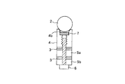
本実施の形態の振動型アクチュエータにおける振動体の基本的な構成は、図1に示す第1の実施の形態と同様であって、内径部にめねじ部が形成された頭部弾性体4と、中心部に穴が形成された中間弾性体5aと後部弾性体5bの間にそれぞれ圧電素子を配置し、後部弾性体5b側から挿入した中心軸部材をなす締結ボルト6を頭部弾性体4のめねじ部に螺着することにより、頭部弾性体4と中間弾性体5aとの間、中間弾性体5aと後部弾性体5bとの間にそれぞれ圧電素子3を挟持して一体的に連結されて形成されている。
【0060】
本実施の形態において、頭部弾性体4と中間弾性体5aとの間に配置される圧電素子3は、振動体に縦振動を励起する第1の圧電素子であり、また中間弾性体5aと後部弾性体5bとの間に配置される圧電素子3は、x−z平面内での曲げ振動を形成する第2の圧電素子と、y−z平面内での曲げ振動を形成する第3の圧電素子であって、前記第2の圧電素子と前記第3の圧電素子は位置的に90°の位相差を有して配置されている。
【0061】
また、頭部弾性体4の先端部は、球体形状の移動体2と接触する軸線に対して斜めの内周面がテーパー面に形成されている。
【0062】
したがって、本実施の形態においても、上記した第1の実施の形態と同様に、振動体に形成される縦振動、2方向の曲げ振動のうち、2つの振動を組み合わせることによって、球体形状の移動体2をx軸、y軸、z軸周りにそれぞれ回転させることができる。
【0063】
例えば、図1の(c)と(d)の組み合わせによってz軸周りに、(b)と(c)の組み合わせによってy軸周りに、(b)と(d)の組み合わせによってx軸周りに移動体2を回転させることができ、移動体2は、互いに直交する3軸周りに回転できる。
【0064】
(第4の実施の形態)
図4は本発明の第4の実施の形態を示す。
【0065】
本実施の形態の振動型アクチュエータにおける振動体の基本的構成は図3に示す第3の実施の形態と同様で、頭部4aに形成される直交3平面内の楕円運動で駆動される移動体2を平板状としている点が第3の実施の形態と異なる。
【0066】
本実施の形態では、頭部弾性体4の頭部4aに移動体2を圧接することで、移動体2はx軸方向、y軸方向およびz軸周りに運動する。例えば、第1の圧電素子を駆動して形成されるz方向の縦振動と、第2の圧電素子を駆動して形成されるx−z平面内の横振動とを約90゜位相差を有して励起すると、振動体の頭部4aにはx−z面内の楕円運動が生じ、頭部4aに接触した移動体2はx軸方向に直進運動する。
【0067】
また、z方向の縦振動とy−z平面内の横振動を位相を約90゜違えて励起すると、頭部4aの端部の点にはy−z面内の楕円運動が生じ、頭部4aに接触した移動体2はy軸方向に直進運動する。
【0068】
さらに、x−z平面内の横振動とy−z平面内の横振動を約90゜の位相差を有して励起すると、頭部4aにはxy面内の楕円運動が生じ、頭部4aに接触した移動体2はz軸周りに回転する。
【0069】
(第5の実施の形態)
図5は本発明の第5の実施の形態を示す。
【0070】
本実施の形態は図3に示す第3の実施の形態の振動型アクチュエータにおける振動体に対して球体形状の移動体2を永久磁石7の磁力により吸引加圧するようにしたもので、頭部弾性体4の先端凹部4b内に永久磁石7を設けるようにしている。
【0071】
(第6の実施の形態)
図6は第6の実施の形態を示す。
【0072】
本実施の形態は図3に示す第3の実施の形態の振動型アクチュエータにおける振動体に対して球体形状の移動体2を電磁石の磁力により吸引加圧するようにしたもので、頭部弾性体4の外周部に設けた凹溝4c内にコイル8を配置し、コイル8に通電することにより電磁石を構成し、この磁力によって移動体2を頭部弾性体4に吸引加圧する。コイル8は振動体の周囲に配置された支持部材30に取り付けられ、また振動体から延びる支持板9の外端部が支持部材30に取り付けられている。
【0073】
なお、コイル8は磁気回路を構成可能であれば、振動体の周囲のいかなる場所に配置されていてもよい。
【0074】
(第7の実施の形態)
図7は本発明の第7の実施の形態を示す。
【0075】
本実施の形態は、図3に示す第3の実施の形態における振動型アクチュエータの振動体に対する球体形状の移動体2の接触性の改善を図るもので、頭部弾性体4の先端凹部4b内に、移動体2の接触部近傍に配した弾性材料で形成された当接体10を配置し、移動体2と頭部弾性体4の接触領域の増加を図っている。
【0076】
このため、振動体に対する移動体2の接触が安定し、出力トルクが増し、また、部品加工時の加工誤差の許容範囲を広げることができる。
【0077】
なお、本実施の形態では、図5に示す第5の実施の形態と同様に、頭部弾性体4の先端凹部4b内に永久磁石7を設け、球体形状の移動体2を永久磁石7の磁力により吸引加圧するようにしている。
【0078】
(第8の実施の形態)
図8は本発明の第8の実施の形態を示す。
【0079】
本実施の形態は、第7の実施の形態と同様に、図3に示す第3の実施の形態における振動型アクチュエータの振動体に対する球体形状の移動体2の接触性の改善を図るもので、振動体における頭部弾性体4の先端凹部4bをばね性を有する筒状のつば部11により形成している。
【0080】
本実施の形態では、不図示の加圧手段により移動体2がばね性を有するつば部11によってある程度の弾性力をもって接触するので、移動体2の球面に対するつば部11の接触面積が増大し、移動体2の接触性が安定することとなり、出力トルクが増し、また部品加工時の加工誤差の許容範囲を広げることができる。
【0081】
なお、本実施の形態では、図5に示す第5の実施の形態と同様に、頭部弾性体4の先端凹部4b内に永久磁石7を設け、球体形状の移動体2を永久磁石7の磁力により吸引加圧するようにしている。
【0082】
(第9の実施の形態)
図9、図10、図11は本発明の第9の実施の形態を示す。
【0083】
本実施の形態は、円柱形状の振動体の具体的構成を示し、頭部弾性体4の後に第1弾性体5cを直接配置し、第1弾性体5cと第2弾性体5dとの間に縦振動を励起するための圧電素子板3a,3bと、振動検出のための圧電素子板3cと、中央部9aが電極板として圧電素子板3aに接触する機能を兼用する支持板9と、電極板12z,12sz,13とが配置される。また第2弾性体5dと第3弾性体5eとの間に、横振動(曲げ振動)を励起する圧電素子板3e,3fと3g,3h、振動検出のための圧電素子板3dと3i、電極板12SA,12A,12SB,12B,13とシート14が配置される。そして、頭部弾性体4の内径部のめねじ部に締結ボルト6の先端ねじ部が螺合することにより、頭部弾性体4、第1弾性体5c、第2弾性体5d、第3弾性体5e、圧電素子板3a〜3i、電極板12、13およびシート14が図示の配列で一体的に挟持され、振動体を構成している。なお、電極板13はグランド電極である。
【0084】
ここで、支持板9は中央の電極板部9aから径方向に延出した腕部が、図11に示す固定部30に固定されることにより振動体を支持するようにしている。なお、振動体自体の固有振動に影響を与えないのであれば、支持板9は板以外の形状でもよい。勿論電極板を兼用するものでなくてもよい。
【0085】
さらに、圧電素子板3d,3e,3fと、圧電素子板3g,3h,3iとは左右が逆極性を有するように分極されていて、曲げ方向に90°の位相差を有して配置されている。なお、シート14は絶縁性を有し、シート14の両側に配置される第2弾性体5dと電極板12、あるいは第3弾性体5eと電極板12が電気的に独立となるようにしている。
【0086】
このように構成された振動体に対し、後述の図19に示す駆動回路より、例えば、圧電素子板3a,3bが挟む電極板12(12Z)が振動体の固有振動数に近い周波数の交流電圧を入力すると、これらの圧電素子板3a,3bから厚さ方向に伸びと縮みを繰り返し、振動体に縦振動を励振する。また、圧電素子板3cは、圧電素子板3a,3bにより励振された縦振動によって歪み、起電力を発生する。この際、圧電素子板3cに接する電極板12(12SZ)から取り出される交流電圧は、振動検出用として用いられる。
【0087】
圧電素子板3e,3fが挟む電極板12(12A)に振動体の固有振動数に近い周波数の交流電圧を入力すると、これらの圧電素子板3e,3fが直径部分を挟んだ両側の部分が厚さ方向に伸びと縮みを交互に繰り返し、振動体に横振動を励振する。
【0088】
また、圧電素子板3dは、圧電素子板3e、3fにより励振された振動体の横振動によって歪み、起電力を発生する。この際、圧電素子板3dに接する電極板12(12SA)から取り出される交流電圧は、振動検出用として用いられる。圧電素子板3d、3eと位置的に90°の位相差を有して配置されている圧電素子板3g、3hを挟む電極板12(12B)に振動体の固有振動数に近い周波数の交流電圧を入力すると、これらの圧電素子板3g、3hが直径部分を挟んだ両側の部分が厚さ方向に伸びと縮みを繰り返し、振動体に横振動(曲げ振動)を励振する。また、圧電素子板3iは、圧電素子板3g、3hにより励振された振動体の横振動(曲げ振動)によって歪み、起電力を発生する。この際、圧電素子板3iに接する電極板12(12SB)から取り出される交流電圧は、振動検出用として用いられる。
【0089】
また、縦振動を励振する圧電素子板3a〜3cの位置は、縦振動1次モードの節となる位置である。さらに、横振動を励振する圧電素子板3d〜3iの位置は、横振動2次モードの腹となる位置である。
【0090】
一方、頭部弾性体4の外周部に形成されたくびれ部(凹部)4cにより、固有振動の振幅が拡大し、固有振動数を低く抑えることができる。また、振動体の中心軸6に施されたくびれ部(凹部)6aにより、主に縦振動の固有振動数を低く抑えることができる。
【0091】
図19は上記した振動体を駆動制御する駆動回路を示すブロック図である。101はシステム全体をコントロールするCPUで、102は発振器、103は移相器、104は選択切り替えスイッチである。105は駆動波形を作る出力回路で、図20に示す回路にょり構成されている。出力回路105Z、105A、105Bはそれぞれ電極板12Z、12A、12Bと接続され、圧電素子3aと3b、3eと3f、3gと3hに交流電圧(交番信号)を印加する。これらの圧電素子は、Z軸方向の縦振動、Z−X平面内の横(曲げ)振動、Z−Y平面内の横(曲げ)振動をそれぞれ励振する。
【0092】
選択切り替えスイッチ104はCPU101からの指令に基づいて、Z,A,Bの3つの出力から2つを選択し、発振器102および移相器103からの2つの信号を出力する。これにより、3軸の回転のうち1軸を選択することができることになる。
【0093】
107はパルス幅を制御するパルス幅制御回路で、圧電素子に印加される交流電圧の振幅を制御することができる。パルス幅により印加電圧をそれぞれ個別独立に変えることで楕円軌跡の縦横比(長軸と短軸の比)を変えることができる。発振器102の発信周波数を振動体の固有振動数に近づけたり、遠ざけたりして振動体の振幅を変え、楕円軌跡の大きさを変えることができる。
【0094】
圧電素子板3c,3d,3iで発生するZ軸方向の縦振動、Z−X平面内の横(曲げ振動)、Z−Y平面内の横(曲げ)振動、それぞれの振動振幅に応じた電圧は電極板12SZ、12SA、12SBを通じて検出回路106からそれぞれの振幅、位相の情報がCPUに入力される。
【0095】
これらの情報に基づき、パルス幅制御回路107、移相器103、発振器102をCP101でコントロールすることで、楕円軌跡を任意の形状に制御することができる。
【0096】
このような制御を行うことにより、以下のことが可能となる。
【0097】
1:振動体の送り方向速度分布が変わるので、移動体の速度を変えることができる。
【0098】
2:摩擦力分布が変わるので、最も摺動損の少ない楕円軌跡をつくることができる。例えば楕円軌跡の傾きについては、移動体の球面に対して楕円の軸が直交するように制御すれば良い。具体的には、図3に示した弾性体4の内周面(軸線に対して斜めに形成されている)の放線方向に楕円軌跡を発生させて、効率向上を図ることができる。
【0099】
あるいは、不図示の回転検出計と電力計の信号をフィードバックして、最も効率の楕円軌跡の状態で駆動することもできる。
【0100】
3:振動体と移動体との当たり方(法線方向の変位と速度)も変わるので、最も衝撃の少ない接触の仕方、あるいは鳴き等の異常なノイズを発生しない楕円軌跡とすることもできる。
【0101】
(第10の実施の形態)
図12は本発明の第10の実施の形態を示す。
【0102】
本実施の形態は、例えば図9に示す支持板9を有する振動体を、例えば任意の方向に移動可能な支持台15を介して支持するようにしてものである。支持台15は円筒形状であり、ロボットアーム等に取り付けられることにより、多自由度振動型アクチュエータを多自由度運動できる関節として利用できる。
【0103】
(第11の実施の形態)
図13は本発明の第11の実施の形態を示す。
【0104】
本実施の形態は、前述した各実施の形態及び後述する図21〜図27も含めた各実施の形態の振動型アクチュエータ40を直列に2つ接続したものを操作腕として左右に設け、制御システム41を介して操作用グローブ16により遠隔操作するようにしたもので、人の関節の角変位を読み取れるようになっている操作用グローブ16と制御システム41の組み合わせでアクチュエータを駆動する遠隔操作システムは公知なので、ここではこれらの構成の説明については省略する。本実施の形態の操作腕は、手元側の振動型アクチュエータ40の移動体42として球体形状のものを使用して、先端側の振動型アクチュエータ40の後端部に取り付け、この先端側の振動型アクチュエータ40の移動体43として操作指部分を有する棒状(振動体の頭部弾性体部分との接触部は球面)のものを使用しており、移動体42、43はヒトの関節と対応した位置に取り付けられ、人の運動に対応した遠隔操作機械(ロボット)を実現できる。なお、遠隔操作機械とは、ヒトの動きに対応して動作する機械である。
【0105】
このような遠隔操作機械は、腹腔鏡下手術やマイクロサージェリーに用いることもできる。腹腔鏡下手術とは患者の体を切開することなく、体内に挿入された内視鏡と鉗子によって行われる手術である。
【0106】
本実施の形態をこれに使用することにより、人の手を入れることのできない患者の腹部の内部で、人の手の複雑な動きを実現できるので、これまでの腹腔鏡下手術よりも緻密な手術を行うことができる。なお、マイクロサージェリーとは、微細な生体組織に対して行う、細かい操作を伴う手術であり、現在は顕微鏡下で直接人の手によって行われている。遠隔操作機械を用いて術者側のスケールと機械側のスケールを調節することで、人の手のスケールでは困難である細かい操作が可能である。
(第12の実施の形態)
図14は第12の実施の形態を示す。
【0107】
本実施の形態は、前述した各実施の形態及び後述する図21〜図27も含めた各実施の形態の振動型アクチュエータ(多自由度振動型アクチュエータ)50をシャーシ17に複数取り付け、また移動体として球体を用いることにより、X−Y平面内を任意に移動できるようにしたもので、並進および回転をすることができるようにしている。なお、図14では、多自由度振動型アクチュエータ50の移動体2が不図示の床と接触するようにしているが、逆に高所等に配置したレールの下面に接触させ、懸垂型の移動機構とすることもできる。
【0108】
(第13の実施の形態)
図15は本発明の第13の実施の形態を示す。
【0109】
本実施の形態は、前述した各実施の形態及び後述する図21〜図27も含めた各実施の形態の振動型アクチュエータ(多自由度振動型アクチュエータ)60の球体形状の移動体2内にカメラ18を配置し、監視カメラやコンピュータへの入力用の撮影装置としたものである。
【0110】
[第14の実施の形態]
図21は本実施の形態の振動型アクチュエータの構造及び駆動原理を示している。単一の振動体100としての円柱形状の弾性体101,102の間に、図21(b)に示すように4分割に分極された電気−機械エネルギ−変換素子としての圧電素子103(同じ位相で4分割に分極された複数枚の圧電素子板が積層されてブロック化されている)が挟持固定されている。この圧電素子103には各分極領域ごとに独立に駆動のための交番信号(電圧)を印加できるようになっている。なお、振動体100の移動体102との接触部(駆動部)となる内周面100aは軸線に対して斜めに形成され、球状の移動体102が若干内部に入り込むようにしている。
【0111】
圧電素子103の各分極領域A〜Dは同極性に分極されており、振動体100をZ軸方向に変位させるためには、
VA =VB =VC =VD =sin ωt
VA =VC =sin ωt、又はVB =VD =sin ωt
の交番信号を供給する。
【0112】
一方、振動体100をX軸方向(Z−X平面内で曲げ振動)に変位させるためには、
VA =sin ωt,VC =−sin ωt
もしくは
VA =cos ωt,VC =−cos ωt
の交番信号を供給する。
【0113】
更に、振動体100をY軸方向(Z−Y平面内で曲げ振動)に変位させるためには、
VB =sin ωt,VD =−sin ωt
もしくは
VB =cos ωt,VD =−cos ωt
の交番信号を供給する。
【0114】
それによって、図21(a)に示したように、Z軸方向、X軸方向、Y軸方向の変位となる。なお、Z軸方向の振動を1次モードとし、X軸方向及びY軸方向の振動を2次モードとすることにより、各軸方向の振動を共振させている。
【0115】
なお、周溝を形成することにより剛性を小さくした第1の部分101aは、X軸方向及びY軸方向の振動での節の位置として、曲げ(屈曲)の変位拡大としての役目を果たす。
【0116】
また、周溝を形成することにより剛性を小さくした第2の部分101bは、Z軸方向の振動での節の位置として、縦の変位拡大としての役目を果たす。
【0117】
図21の実施の形態は、前述した第1〜第13の実施の形態のように、縦振動専用の電気−機械エネルギー変換素子を必要とせず、基本的には複数の分極領域へ選択的に交番信号を供給することによって、3軸方向への振動体100の変位を可能としている。
【0118】
次に球状の移動体102を各軸回りに回転させるための交番信号の供給について説明する。
【0119】
X軸回りに移動体102を回転させる場合には、Z軸方向の変位とY軸方向の変位を、例えば90°の位相差をもって与える。
【0120】
すなわち
VA =VB =VC =VD =sin ωt(Z軸方向変位)
と、
VB =cos ωt,VD =−cos ωt(Y軸方向変位)
の交番信号を各対応する分極領域A〜Dに供給する。
【0121】
すなわち、次式のようになる。
【0122】
VA =sin ωt
VB =sin ωt+cos ωt=√2sin (ωt+π/4)
VC =sin ωt
VD =sin ωt−cos ωt=√2sin (ωt−π/4)
又、Y軸回りに移動体102を回転させる場合には、Z軸方向の変位とX軸方向の変位を、例えば90°の位相差をもって与える。
【0123】
VA =VB =VC =VD =sin ωt(Z軸方向変位)
VA =sin ωt,VC =−sin ωt(X軸方向変位)
すなわち、次式のようになる。
【0124】
VA =√2sin (ωt+π/4)
VB =sin ωt
VC =√2sin (ωt−π/4)
VD =sin ωt
により、(Z軸方向変位+X軸方向変位)の交番信号を各対応する分極領域A〜Dに供給する。
【0125】
更に、Z軸回りに移動体102を回転させる場合には、X軸方向の変位とY軸方向の変位を、例えば90°位相差をもって与える。
【0126】
すなわち、
VA =sin ωt
VB =cos ωt
VC =−sin ωt
VD =−cos ωt
により、(X軸方向変位+Y軸方向変位)の交番信号を各対応する分極領域A〜Dに供給する。
【0127】
なお、Z軸方向の変位を実現する際に、圧電素子103の分極領域A及びCのみを用いた場合には、次のように各分極領域への交番信号の供給は変わることになる。
【0128】
すなわち、
X軸回りの回転の際には
VA =VC =sin ωt
VB =cos ωt
VD =−cos ωt
となり、
Y軸回りの回転の際には
VA =cos ωt
VB =sin ωt
VC =−cos ωt
VD =sin ωt
となり、
Z軸回りの回転の際には
VA =sin ωt
VB =cos ωt
VC =−sin ωt
VD =−cos ωt
となる。
【0129】
なお、位相差を90°とせずに変えることにより、楕円運動の形状が変化し、移動体102と振動体100の駆動部との当接角度に合わせた高トルクでの駆動を可能とする。
【0130】
[第15の実施の形態]
図22は本実施の形態の振動型アクチュエータの構造及び変位の形態を示している。
【0131】
この実施の形態は単一の振動体200として、円柱形状の弾性体201と円板状の弾性体202とを接合させたものである。弾性体201は実際には2分割されて間に、2枚の第1の電気−機械エネルギ−変換素子としての圧電素子203,204を挟持している。又、円板状の弾性体202には表面に4つの第2の電気−機械エネルギー変換素子としての圧電素子205a〜205dが設けられている。
【0132】
圧電素子203は駆動部となる弾性体201を図22(c)に示すようにX軸方向に変位させるためのものであり、図10での圧電素子3e,3fと同じ役目を果たす。又、圧電素子204は弾性体201をY軸方向に変位させるためのものであり、図10での圧電素子3g,3hと同じ役目を果たす。なお、圧電素子203と204とは分極位相を90°ずらしている。
【0133】
一方、圧電素子205a〜dは全て同特性に分極されており、円板状の弾性体202を図22(d)に示すように屈曲させることにより、駆動部となる弾性体201をZ軸方向に変位させるものである。
【0134】
駆動部となる弾性体201には球状の移動体206が第14の実施の形態と同様に当接しており、圧電素子204と圧電素子205a〜dに交番信号を例えば90°位相をずらして供給することにより、X軸回りに移動体206を回転させることができる。又、圧電素子203と圧電素子205a〜dに交番信号を例えば90°位相をずらして供給することにより、Y軸回りに移動体206を回転させることができる。
【0135】
一方、Z軸回りに移動体206を回転させる場合には、圧電素子203と204に交番信号を例えば90°位相をずらして供給することになる。
【0136】
なお、移動体206を重力方向に関係なく、常に弾性体201に圧接させるためには、図23にて示したように弾性体201の内部に永久磁石210を設け、更に移動体206自体を磁性材によって形成するやり方がある。この構造によって、移動体206は磁石の吸着力によって重力方向にかかわらず、常に振動体200と圧接することができる。
【0137】
なお、位相差を90°としないで任意の位相差を設定し、楕円運動の形状を変えることも効果がある。
【0138】
[第16の実施の形態]
図24は本実施の形態の振動型アクチュエータの構造及び変位の形態を示している。
【0139】
この実施の形態は単一の振動体300として、円柱形状の弾性体301と円板状の弾性体302とを接合させたものである。弾性体301の内部には永久磁石(不図示)が組込まれており、磁性体で形成された移動体306を常時、磁力により吸着して圧接力を得るようにしている。
【0140】
弾性体302には、表面に4つの電気−機械エネルギ−変換素子としての圧電素子(分極領域)303a〜dが設けられている。圧電素子303a〜dは選択的に交番信号が供給されることにより、図24(b)〜(d)に示したように、駆動部としての弾性体301をX軸方向に変位させ、Y軸方向に変位させ、もしくはZ軸方向に変位させることができる。
【0141】
そして、移動体306をX軸回りに回転させる際には、Y軸方向の変位(図24(c))とZ軸方向に変位(図24(d))を、例えば90°位相差をもうけて与えればよく、Y軸回りの際にはX軸方向の変位(図24(b)とZ軸方向の変位(図24(d))を、例えば90°の位相差を設けて与える。更に、Z軸回りに回転させたい際には、X軸方向に変位(図24(b))とY軸方向の変位(図24(c))を、例えば90°の位相差を設けて与える。なお、位相差を90°とせずに任意に設定して、楕円運動の形状を変えることも効果がある。
【0142】
各圧電素子303a〜dへの交番信号の供給については、上述の第14実施の形態の場合と同じであり、詳しい説明は省略する。
【0143】
[第17の実施の形態]
図25は本実施の形態の振動型アクチュエータの構造を示すもので、単一の振動体400として円柱形状の複数の弾性体401,402,403を形成し、弾性体401と402の間に圧電素子404を挟持し、弾性体402と403の間に圧電素子405を挟持している。3つの弾性部材401〜403は締結部材としてのボルト407によって締結されている。なお、406は球状の移動体である。
【0144】
本実施の形態では、振動体400と移動体406との圧接を、エアによる吸引によって行うようにしたことを特徴としている。すなわち、ホース408を振動体400の駆動部近傍の凹部401aに挿入し、このホース408によってエアを吸引することにより、駆動部近傍に吸着力を発生させ、移動体406を重力方向にかかわらず常に振動体400と圧接させることができる。
【0145】
なお、410はケースであって、弾性体401と402の間に挟持された支持部材411の外端部が固定されることにより、振動体400を支持している。
【0146】
[第18の実施の形態]
図26(a)に示した本実施の形態は第17実施の形態の変形例を示すもので、移動体406を振動体400の駆動部に圧接させる他の構造を示している。
【0147】
具体的にはケース410の上部には、ドーム状の上カバー412が軸受としてのボール413によりケース410に対して回転自在に設けられている。上カバー412には4ヵ所で、コイルバネ414によって移動体406を振動体400の方向に付勢する押し付け部材415が移動自在に設けられている。この押し付け部材415の付勢力により、移動体406は振動体400に重力方向にかかわらず圧接できることになる。振動体400自体は支持部材411によりケース410に支持されている。
【0148】
なお、移動体406には実際の駆動部としての突部406aが上カバー412より突出形成されており、移動体406をどの方向にも回転できるように、上カバー406には図26(b)に示すように十字状の切欠き412aが形成されている。
【0149】
移動体406の突部406aは切欠き412a内に挿入されており、且つ上ケース412自体をケース410に対して回転自在としていることから、突部406aどのような方向に回転(揺動)したとしても、上カバー412を回転させてどれかの切欠き412a内に入り込み、制限を受けることがないようにしている。
【0150】
[第19の実施の形態]
図27(a)に示した本実施の形態は第18実施の形態の変形例を示すもので、上カバー420はボール413によってケース410に対して回転自在に支持されているが、皿バネ422をボール413の軸受部に追加している。この皿バネ422は実際にはボール押え部材423を間に入れて設けられ、上ケース420自体をケース410に対して図において下方向となる、移動体406と振動体400との圧接方向に付勢する役目を果たす。
【0151】
上ケース420の内側には3ヵ所に固定の押し付け部材424が形成されており、押し付け部材424によって移動体406は振動体に対して圧接されることになる。
【0152】
上ケース420には図27(b)に示すように略Y字状の切欠き420aが形成されている。この切欠き420aの役目は、上述した図26(b)での切欠き412aと同じである。なお、図27(c)には外観図を示した。
【0153】
図26,27に示した上カバー412,420を設けた実施の形態では、移動体406が実質上カバーされ、触れられることによる油やゴミ等による摩擦係数の変化を防止することができる。
【0154】
[第20の実施の形態]
本実施の形態は移動体をどのような任意な角度にも回転できるようにしたものである。図29の破線はX−Z平面内でX軸からZ軸方向にθ1 傾いた軸を示し、図29の実線はX−Y平面内でX軸からY軸方向にθ2 傾いた軸回りの回転を示している。
【0155】
そして、基準となる各X軸、Y軸、Z軸に対して異なる軸方向にθ1 ,θ2 傾いた軸回りの回転を実現できるようにすれば、それ以外でも任意の方向の軸回りの回転が実現できるようになる。
【0156】
具体例として、X軸を基準として、異なる方向にθ1 ,θ2 傾むけた軸回りの回転を実現するやり方について説明する。
【0157】
図28に示すように、X−Z平面内でX軸からθ1 傾いた軸回りの回転は、
ωθ1 =Aωx+Bωz
ただしB/A=tan θ1 として定義できる(|ωx|=|ωz|である)。
【0158】
図29に示すようにX−Y平面内でX軸からθ2 傾いた軸回りの回転は、
ωθ2 =Cωx+Dωy
ただしD/C=tan θ2 として定義できる(|ωx|=|ωy|である)。
【0159】
更に、θ1 及びθ2 傾いた軸回りの回転は、
ω(θ1 +θ2 )=ωθ1 +ωθ2 =Aωx+Bωy+Cωz
ただし、B/A=tan θ2 ,C/A=tan θ1 として定義できる。
【0160】
最初に位相差を90°とした場合で説明する。
【0161】
振動型アクチュエータとしては図1〜10のタイプを用い、図10に示した各電極板12A,12B,12Zへどのような交番信号を供給することにより、任意の角度の回転軸による駆動を可能とするかを説明する。
【0162】
X軸回りの回転ωxは
V12Z =sin ωt(Z方向)
V12B =cos ωt(Y方向)」
で行える。
【0163】
Y軸回りの回転ωyは
V12Z =sin ωt(Z方向)
V12A =cos ωt(X方向)
で行える。
【0164】
そして、Z軸回りの回転ωZ は
V12A =sin ωt(X方向)
V12B =cos ωt(Y方向)
で行える。
【0165】
次に、X−Z平面内でX軸からθ1 傾いた軸回りの回転は、
V12A =Bsin ωt
V12B =Acos ωt+Bcos ωt=(A+B)cos ωt
V12Z =Asin ωt
ただし、B/A=tan θ1 となる。
【0166】
X−Y平面内でX軸からθ2 傾いた軸回りの回転は、
V12A =Dcos ωt
V12B =Ccos ωt
V12Z =Csin ωt+Dsin ωt=(C+D)sin ωt
ただし、D/C=tan θ2 となる。
【0167】
そして、θ1 及びθ2 を合わせた軸回りの回転は、
V12A =Bcos ωt+Csin ωt=√(B2 +C2 )sin (ωt+α)
V12B =Acos ωt+Ccos ωt=(A+C)cos ωt
V12Z =Asin ωt+Bsin ωt=(A+B)sin ωt
ただし、B/A=tan θ2 ,B/C=tan α, C/A=tan θ1 とする。
【0168】
次に、図21,24に示した振動型アクチュエータを用いた場合について説明する。ただし、以下の説明は各圧電素子の領域A〜Dに対してどのような交番信号を供給するかについて述べる。
【0169】
VA 〜VD とは図21(b)では各分極領域A〜Dに対応し、図24(a)では各圧電素子303a〜303dに対応する。
【0170】
X−Z平面内でX軸よりθ1 傾いた軸回りの回転は、
VA =Asin ωt+Bsin ωt=(A+B)sin ωt
VB =Acos ωt+Bcos ωt=(A+B)cos ωt
VC =Asin ωt−Bsin ωt=(A−B)sin ωt
VD =−Acos ωt−Bcos ωt=−(A+B)cos ωt
ただし、B/A=tan θ1 となる。
【0171】
X−Y平面内でX軸からθ2 傾いた軸回りの回転は、
VA =Csin ωt+Dcos ωt=√(C2 +D2 )sin (ωt+θ2 )
VB =Ccos ωt−Dsin ωt=√(C2 +D2 )cos (ωt+θ2 )
VC =Csin ωt−Dcos ωt=−√(C2 +D2 )sin (−ωt+θ2 )
VD =−Ccos ωt+Dsin ωt=−√(C2 +D2 )cos (ωt+θ2 )
ただし、D/C=tan θ2 となる。
【0172】
そして、θ1 及びθ2 を合わせた軸回りの回転は、

【0173】
図30は上記した図21,24の振動体を駆動制御する駆動回路を示すブロック図である。
【0174】
101はシステム全体をコントロールするCPUで、102は発振器、103A,103Bは位相器、104は選択切り替えスイッチである。
【0175】
105Z,105A,105Bは駆動波形を作る出力回路で、出力回路105Z,105A,105Bはそれぞれ分極領域303a〜dと接続され、交流電圧(交番信号)を印加する。これらの圧電素子は、Z軸方向の振動、X軸方向の振動、Y軸方向の振動をそれぞれ励振する。
【0176】
発振器102の発振周波数を振動体の固有振動数に近づけたり、遠ざけたりして振動体の振幅を変えることができる。
【0177】
107はパルス幅を制御するパルス幅制御回路で、圧電素子に印加される交流電圧の振幅を制御することができる。パルス幅の制御により印加電圧をそれぞれ個別独立に変えること、振動振幅もそれぞれ個別独立に変えることができる。
【0178】
位相器103A,103Bは、発振器102の出力信号の位相を変えることができる。
【0179】
第20の実施の形態に示した前述の式に従った、印加電圧、位相差をもった3つの印加電圧をそれぞれの圧電素子に与えることにより、任意の角度の軸まわりの回転を駆動できる。
【0180】
圧電素子103(303)で発生するZ軸方向の振動、X軸方向の振動、Y軸方向の振動、それぞれの振動振幅に応じた電圧は検出信号12SZ,12SA,12SBを通じて検出回路106からそれぞれの振幅、位相の情報がCPU101に入力される。
【0181】
これらの情報に基づき、パルス幅制御回路107、位相器103A、位相器103B、発振器102をCPU101でコントロールし、各振動が所定の振幅、位相差であるように調整される。
【0182】
また、回転検出計108の信号をフィードバックしており、より精度の高い回転軸及び回転数の制御が可能となる。
【0183】
さらに、検出回路からの情報に基づき、パルス幅制御回路107、位相器103A、位相器103B等をコントロールすることで、振動の楕円軌跡の形状を任意に制御することができる。
【0184】
このような制御を行うことにより、以下のことが可能となる。
【0185】
1:振動体の送り方向速度分布が変わるので、移動体の速度を変えることができる。
【0186】
2:摩擦力分布が変わるので、最も摺動損の少ない楕円軌跡をつくることができる。例えば楕円軌跡の傾きについては、移動体の球面に対して楕円の軸が直交するように制御すれば良い。具体的には、図21に示した弾性体100の内周面100a(軸線に対して斜めに形成されている)の放線方向に楕円軌跡を発生させて、効率向上を図ることができる。
【0187】
あるいは、不図示の回転検出計と電力計の信号をフィードバックして、最も効率の良い楕円軌跡の状態で駆動することもできる。
【0188】
3:振動体と移動体との当たり方(法線方向の変位と速度)も変わるので、最も衝撃の少ない接触の仕方、あるいは鳴き等の異常なノイズを発生しない楕円軌跡とすることもできる。
【0189】
以上説明した第14の実施の形態〜第20の実施の形態の振動型アクチュエータを、図13、図14、図15に示す振動型アクチュエータに代えることができることは言うまでもない。
【0190】
また、図21の(b)に示すように、圧電素子のx軸,y軸を分極領域の中央に設定しているが、これに限定されるものではない。
【0191】
さらに、移動体に対して振動体を移動させるようにしても良い。
【0192】
【発明の効果】
本発明によれば、振動体と接触体とを任意の方向に相対移動させることができる。
【図面の簡単な説明】
【図1】本発明の第1の実施の形態を示し、(a)は振動体の外観斜視図、(b)は振動体の縦振動の1次モード、(c),(d)は横振動の2次モードを示す。
【図2】本発明の第2の実施の形態を示し、(a)は振動体の外観斜視図、(b)は振動体の縦振動の1次モード、(c),(d)は横振動の2次モードを示す。
【図3】本発明の第3の実施の形態を示す振動型アクチュエータの断面図。
【図4】本発明の第4の実施の形態を示す振動型アクチュエータの断面図。
【図5】本発明の第5の実施の形態を示す振動型アクチュエータの断面図。
【図6】本発明の第6の実施の形態を示す振動型アクチュエータの断面図。
【図7】本発明の第7の実施の形態を示す振動型アクチュエータの断面図。
【図8】本発明の第8の実施の形態を示す振動型アクチュエータの断面図。
【図9】本発明の第9の実施の形態を示す振動型アクチュエータの外観斜視図。
【図10】図9の振動体の分解斜視図。
【図11】(a)、(b)は図9の振動体を支持した状態を示す側面図と上面図。
【図12】本発明の第10の実施の形態を示す側面図。
【図13】本発明の第11の実施の形態を示す概略図。
【図14】本発明の第12の実施の形態を示す側面図。
【図15】本発明の第13の実施の形態を示す外観斜視図。
【図16】リング状振動体の斜視図。
【図17】従来の球面振動型アクチュエータの斜視図。
【図18】従来の振動型アクチュエータの断面図。
【図19】第9の実施の形態の駆動回路図。
【図20】図19の出力回路の回路図。
【図21】第14の実施の形態を示し、(a)は振動体の外観斜視図とそれぞれの方向における振動変位、(b)は圧電素子の平面図。
【図22】第15の実施の形態を示し、(a)は振動体の外観斜視図、(b)は圧電素子の配置方向と分極方向を示す図、(c)、(d)は振動体の変位を示す図。
【図23】図22の振動体と接触体との吸引保持手段を示す図。
【図24】第16の実施の形態を示し、(a)は振動体の外観斜視図、(b)、(c)、(d)は振動体の変位を示す図。
【図25】第17の実施の形態を示す振動型アクチュエータの縦断面図。
【図26】第18の実施の形態の振動型アクチュエータを示し、(a)は(b)のA−A’矢視縦断面図、(b)は(a)の上面図。
【図27】第19の実施の形態の振動型アクチュエータを示し、(a)は(b)のB−B’矢視縦断面図、(b)は(a)の上面図、(c)は側面図。
【図28】第20の実施の形態の原理を説明するためのベクトル線図。
【図29】第20の実施の形態の原理を説明するためのベクトル線図。
【図30】第20の実施の形態の駆動回路のブロック図。
【符号の説明】
1、101、102、201、202、301、302、401〜403 弾性体
2、102、206、306、406 移動体
3、103、203、204、404、405 圧電素子
3a,3b 縦振動用圧電素子
3c 縦振動検出用圧電素子 3e〜3h 横振動用圧電素子
3d,3i 横振動検出用圧電素子
303a〜303d 圧電素子
4 頭部弾性体 4a 頭部先端凹部
4b 凹溝 4c くびれ(凹部)
5a 中間弾性体 5b 後部弾性体
5c 第1弾性体 5d 第2弾性体
5e 第3弾性体
6、407 締結ボルト 6a 締結シャフト凹部
7 永久磁石 8 コイル
9 支持板 9a 中央部
10 当接体 11 つば部
12 電極板 13 グランド電極板
14 シート 15 支持台
16 グローブ 17 シャーシ
18 カメラ 19 振動体
19a 弾性体 19b 圧電素子
20a,20b 移動体 21 バネ
30 任意支持台 40,50,60 振動体
41 制御システム 42,43 移動体
408 ホース 410 ケース
411 支持部材 412 上カバー
413 ボール 414 コイルバネ
415 押し付け部材[0001]
BACKGROUND OF THE INVENTION
The present invention relates to a vibration type actuator and a vibration type driving device.
[0002]
[Prior art]
As a vibration type actuator that generates motions around multiple axes, for example, Journal of Precision Engineering (Vol. 61, No. 3, pp. 1227-1230, 1995) or Nikkei Mechanical (No. 5, pp. 26-27, 1997). 4.28) discloses a spherical vibration actuator.
[0003]
In this spherical vibration type actuator, a spherical body is used as a moving body, and this spherical moving body (rotor) is rotated around two or three of the three orthogonal axes. A plurality of vibrating bodies (stators) that generate rotational force by vibration (for example, traveling waves) about one axis are arranged so as to be in pressure contact with the moving body.
[0004]
As such spherical vibration type actuators, two-degree-of-freedom type using four vibrating bodies and three-degree-of-freedom type using three vibrating bodies have been developed.
[0005]
Further, the vibrating body used in the spherical vibration type actuator is the same as the vibrating body of a ring type vibration type actuator used for driving an autofocus lens of a camera, for example. Show shape. This vibrating
[0006]
As shown in FIG. 17, a spherical vibration type actuator, for example, a two-degree-of-freedom type spherical vibration type actuator, arranges two pairs of opposed
[0007]
Further, as other vibration type actuators that generate motions around multiple axes, Third International Conference on Motion and Vibration Control, Chiba, September, 1-6, 1996, pp. 11-29. A piezoelectric manipulator described in K9-K15 has been proposed. The configuration is shown in FIG.
[0008]
The piezoelectric manipulator includes a vibrating
[0009]
Then, by applying an appropriate AC voltage to each of the divided electrodes so as to adjust the vibration excited in the vibrating
[0010]
This driving principle is to generate an elliptical motion at the contact point between the hemispherical moving
[0011]
[Problems to be solved by the invention]
However, since the conventional spherical vibration type actuator shown in FIG. 17 uses a plurality of vibrating bodies, the following difficulties have been pointed out.
[0012]
{Circle around (1)} In order to use a plurality of vibrators for rotation around one axis, it is necessary to match the characteristics of the vibrators.
[0013]
{Circle around (2)} Since there are a plurality of vibrating bodies around the moving body, it is difficult to reduce the size and the space efficiency is poor.
[0014]
{Circle around (3)} Since another vibrating body around the shaft that is not used for driving is in pressure contact with the moving body, it becomes a resistance to rotation, and there are problems of efficiency and heat generation.
[0015]
Further, the following problems have been pointed out with respect to the vibration actuator of the conventional cylindrical vibrator shown in FIG.
[0016]
{Circle around (1)} Since an alternating signal is input to a plurality of electrodes provided on the peripheral surface of the vibrating body in accordance with the driving direction, the input signal differs for each electrode, and thus complicated control is required.
[0017]
{Circle around (2)} The hemispherical moving
[0020]
[Means for Solving the Problems]
The vibration type actuator according to the present invention isA vibrating body in which a columnar elastic body is joined on a plate-shaped elastic body, a contact body that contacts the columnar elastic body, and an in-plane perpendicular to the longitudinal direction of the columnar elastic body provided on the columnar elastic body The first electro-mechanical energy conversion element for generating vibrations displaced in two directions orthogonal to each other in the columnar elastic body and the plate-like elastic body, and bending the plate-like elastic body The plate-like elastic body has a second electro-mechanical energy conversion element for generating a vibration displaced in a direction orthogonal to the two directions. Here, out of the three displacements generated in the columnar elastic body and the plate-shaped elastic body, contact with the contact body in the columnar elastic body is performed using a synthetic vibration in which displacements in at least two directions are selectively combined. A circular or elliptical motion in any direction is formed in the part.
[0040]
DETAILED DESCRIPTION OF THE INVENTION
(First embodiment)
FIG. 1 shows a first embodiment of the present invention.
[0041]
FIG. 1 shows the driving principle of the vibration type actuator according to the present embodiment, which is shown in FIGS. 1B, 1C, and 1D between cylindrical
[0042]
In the present embodiment, the
[0043]
Here, when an alternating signal having a phase difference of, for example, 90 ° is applied to the second piezoelectric element and the third piezoelectric element, z is formed on the surface of the vibrating body by combining two bending vibrations with respect to the vibrating body. An elliptical motion around the axis (in the xy plane) is formed. In this case, since the natural frequency of the vibrating body about the x-axis and the y-axis is substantially the same, an alternating signal having this natural frequency as the driving frequency is applied to the second piezoelectric element and the third piezoelectric element. In this case, the above-described elliptical vibration is generated.
[0044]
Next, when an alternating signal having a frequency substantially equal to the natural frequency in the z-axis direction of the vibrating body is applied to the first piezoelectric element, the vibrating body repeats longitudinal vibration in the primary mode at a constant period. become.
[0045]
At that time, when an alternating signal is applied to the second piezoelectric element so as to be excited by one cycle of vibration that is coincident (substantially coincident) with one cycle of the longitudinal vibration that vibrates, the surface of the vibrator An elliptical motion in the xz plane is generated at the upper point, and a driving force in the x-axis direction (around the y-axis) is obtained. In this case, since the natural frequency in the z-axis direction of the vibrating body is different from the natural frequency of the primary mode of the bending vibration in the xz plane, as shown in FIG. The second piezoelectric element is driven in the secondary mode of the natural frequency with respect to the bending vibration in the x-axis direction so that the period of the longitudinal vibration and the period of the bending vibration coincide with each other.
[0046]
Similarly, when an alternating signal is applied to the third piezoelectric element so as to be excited by a vibration of one cycle that coincides (substantially coincides) with one cycle of the longitudinal vibration that the vibrating member vibrates, An elliptical motion in the yz plane is generated at a point on the surface, and a driving force in the y-axis direction (around the x-axis) is obtained. In this case, the natural frequency in the z-axis direction of the vibrating body is different from the natural frequency of the bending vibration in the yz plane. Therefore, as shown in FIG. By driving the third piezoelectric element in a secondary mode having a natural frequency with respect to bending vibration, the period of longitudinal vibration and the period of bending vibration are made to coincide with each other.
[0047]
That is, by applying an alternating signal having a frequency close to the natural frequency of the vibrating
[0048]
Then, by selectively applying an alternating signal to any two of the first piezoelectric element, the second piezoelectric element, and the third piezoelectric element, the longitudinal vibration of the vibrating
[0049]
Therefore, when the moving body is pressed against a part of the vibrating body, the moving body can be driven in a plurality of directions.
[0050]
The driving principle of a conventional piezoelectric actuator is that an elliptical motion about one axis is formed at a point on the surface of the elastic body by applying an alternating signal with a phase shift to the two driving phases of the piezoelectric element constituting the vibrating body. However, in the present embodiment, by combining three-phase piezoelectric elements (first piezoelectric element, second piezoelectric element, and third piezoelectric element), three axes (three orthogonal planes) are combined. In addition to the realization of the vibration type actuator that enables driving in three orthogonal planes with a single vibrating body, it is possible to further reduce the size.
[0051]
(Second Embodiment)
FIG. 2 shows a second embodiment of the present invention.
[0052]
In the first embodiment shown in FIG. 1 described above, the vibrating body in the vibration type actuator has a columnar shape. However, in this embodiment, the vibrating body has a prismatic shape, and the
[0053]
In the present embodiment, for example, the second piezoelectric element is formed by arranging a second piezoelectric element and a third piezoelectric element that form lateral vibration (bending vibration) on two adjacent side surfaces of the prismatic
[0054]
Also in the case of the present embodiment, an alternating signal similar to that of the first embodiment is applied to the first piezoelectric element, the second piezoelectric element, and the third piezoelectric element, and the first piezoelectric element is supplied to the first piezoelectric element. When the alternating signal is applied, the vibrating body vibrates longitudinally as shown in FIG. 2B, and when the alternating signal is applied to the second piezoelectric element, the vibrating body becomes xz as shown in FIG. The vibrating body bends and vibrates in the yz plane as shown in FIG. 2D by applying an alternating signal to the third piezoelectric element.
[0055]
Therefore, as in the first embodiment, a driving force in three planes orthogonal to each other can be obtained by combining two of these three types of vibration.
[0056]
In this embodiment, since a vibrating body can be obtained by sticking a piezoelectric element to a prismatic side surface, it is easy to manufacture the vibrating body, and only two piezoelectric elements for bending vibration are attached to adjacent side surfaces. Thus, the position (phase difference) of both piezoelectric elements can be defined.
[0057]
In the first embodiment and the second embodiment described above, if the vibrating body is fixed, a contact member (indicated by a broken line in the figure) that makes pressure contact with the driving surface of the vibrating body is used as a moving body. A driving force can be applied in the orthogonal three-axis directions, and conversely, if the contact body is fixed, a driving force can be applied to the vibrating body in the three-axis directions orthogonal to the contact body.
[0058]
(Third embodiment)
FIG. 3 shows a third embodiment of the present invention.
[0059]
The basic configuration of the vibrating body in the vibration type actuator of the present embodiment is the same as that of the first embodiment shown in FIG. 1, and the head
[0060]
In the present embodiment, the
[0061]
In addition, the distal end portion of the head
[0062]
Therefore, also in the present embodiment, as in the first embodiment described above, the movement of the spherical shape is achieved by combining two vibrations of the longitudinal vibration and the bending vibration in two directions formed on the vibrating body. The
[0063]
For example, the combination of (c) and (d) in FIG. 1 moves around the z axis, the combination of (b) and (c) around the y axis, and the combination of (b) and (d) around the x axis. The
[0064]
(Fourth embodiment)
FIG. 4 shows a fourth embodiment of the present invention.
[0065]
The basic configuration of the vibrating body in the vibration type actuator of the present embodiment is the same as that of the third embodiment shown in FIG. 3, and a moving body driven by an elliptical motion in three orthogonal planes formed on the
[0066]
In the present embodiment, the moving
[0067]
Further, when the longitudinal vibration in the z direction and the lateral vibration in the yz plane are excited with a phase difference of about 90 °, elliptical motion in the yz plane occurs at the end point of the
[0068]
Further, when the transverse vibration in the xz plane and the transverse vibration in the yz plane are excited with a phase difference of about 90 °, elliptical motion in the xy plane occurs in the
[0069]
(Fifth embodiment)
FIG. 5 shows a fifth embodiment of the present invention.
[0070]
In this embodiment, the spherical moving
[0071]
(Sixth embodiment)
FIG. 6 shows a sixth embodiment.
[0072]
In this embodiment, the spherical moving
[0073]
Note that the
[0074]
(Seventh embodiment)
FIG. 7 shows a seventh embodiment of the present invention.
[0075]
This embodiment is intended to improve the contact of the spherical moving
[0076]
For this reason, the contact of the
[0077]
In the present embodiment, as in the fifth embodiment shown in FIG. 5, the
[0078]
(Eighth embodiment)
FIG. 8 shows an eighth embodiment of the present invention.
[0079]
As in the seventh embodiment, the present embodiment is intended to improve the contact property of the spherical moving
[0080]
In the present embodiment, the
[0081]
In the present embodiment, as in the fifth embodiment shown in FIG. 5, the
[0082]
(Ninth embodiment)
9, 10 and 11 show a ninth embodiment of the present invention.
[0083]
The present embodiment shows a specific configuration of a columnar vibrating body, in which a first
[0084]
Here, the
[0085]
Further, the
[0086]
For the vibrator configured as described above, from the drive circuit shown in FIG. 19 described later, for example, the electrode plate 12 (12Z) sandwiched between the
[0087]
When an alternating voltage having a frequency close to the natural frequency of the vibrating body is input to the electrode plate 12 (12A) sandwiched between the
[0088]
Further, the
[0089]
The positions of the
[0090]
On the other hand, the constricted portion (recessed portion) 4c formed on the outer peripheral portion of the head
[0091]
FIG. 19 is a block diagram showing a drive circuit that drives and controls the vibrating body. A
[0092]
The
[0093]
A pulse
[0094]
Voltages corresponding to longitudinal vibrations in the Z-axis direction generated in the
[0095]
Based on this information, the elliptical locus can be controlled to an arbitrary shape by controlling the pulse
[0096]
By performing such control, the following becomes possible.
[0097]
1: Since the speed distribution in the feeding direction of the vibrating body changes, the speed of the moving body can be changed.
[0098]
2: Since the frictional force distribution changes, an elliptical locus with the least sliding loss can be created. For example, the inclination of the elliptic trajectory may be controlled so that the axis of the ellipse is orthogonal to the spherical surface of the moving object. Specifically, it is possible to improve efficiency by generating an elliptical locus in the radial direction of the inner peripheral surface (formed obliquely to the axis) of the
[0099]
Alternatively, it is also possible to feed back signals from a rotation detector and a wattmeter (not shown) and drive in the state of the most efficient elliptical locus.
[0100]
3: Since the way of contact between the vibrating body and the moving body (displacement and speed in the normal direction) also changes, it is possible to make an elliptical locus that does not generate abnormal noise such as squealing or the like with the least impact.
[0101]
(Tenth embodiment)
FIG. 12 shows a tenth embodiment of the present invention.
[0102]
In this embodiment, for example, a vibrating body having the
[0103]
(Eleventh embodiment)
FIG. 13 shows an eleventh embodiment of the present invention.
[0104]
In the present embodiment, a control system is provided on the left and right as operating arms, in which two vibration-
[0105]
Such a remote control machine can also be used for laparoscopic surgery and microsurgery. Laparoscopic surgery is a surgery performed with an endoscope and forceps inserted into the body without incising the patient's body.
[0106]
By using this embodiment for this, it is possible to realize a complicated movement of the human hand inside the abdomen of the patient into which the human hand cannot be put, so it is more precise than conventional laparoscopic surgery Surgery can be performed. Microsurgery is an operation involving fine operations performed on a fine living tissue, and is currently performed directly by a human hand under a microscope. Adjusting the scale on the operator side and the scale on the machine side using a remote control machine makes it possible to perform detailed operations that are difficult with human hands.Is possible.
(Twelfth embodiment)
FIG. 14 shows a twelfth embodiment.
[0107]
In the present embodiment, a plurality of vibration type actuators (multi-degree-of-freedom vibration type actuators) 50 of the respective embodiments including the above-described embodiments and FIGS. By using a sphere as an object, it can be arbitrarily moved in the XY plane so that it can be translated and rotated. In FIG. 14, the moving
[0108]
(Thirteenth embodiment)
FIG. 15 shows a thirteenth embodiment of the present invention.
[0109]
In this embodiment, a camera is installed in the spherical moving
[0110]
[Fourteenth embodiment]
FIG. 21 shows the structure and driving principle of the vibration type actuator of this embodiment. Between the cylindrical
[0111]
The polarization regions A to D of the
VA= VB= VC= VD= Sin ωt
VA= VC= Sin ωt or VB= VD= Sin ωt
The alternating signal is supplied.
[0112]
On the other hand, in order to displace the vibrating
VA= Sin ωt, VC= -Sin ωt
Or
VA= Cos ωt, VC= -Cos ωt
The alternating signal is supplied.
[0113]
Furthermore, in order to displace the vibrating
VB= Sin ωt, VD= -Sin ωt
Or
VB= Cos ωt, VD= -Cos ωt
The alternating signal is supplied.
[0114]
As a result, as shown in FIG. 21A, the displacement is in the Z-axis direction, the X-axis direction, and the Y-axis direction. The vibration in each axial direction is resonated by setting the vibration in the Z-axis direction as the primary mode and the vibration in the X-axis direction and the Y-axis direction as the secondary mode.
[0115]
The
[0116]
Further, the
[0117]
Unlike the first to thirteenth embodiments described above, the embodiment of FIG. 21 does not require an electro-mechanical energy conversion element dedicated to longitudinal vibration, and is basically selectively used for a plurality of polarization regions. By supplying the alternating signal, the
[0118]
Next, supply of an alternating signal for rotating the spherical moving
[0119]
When the moving
[0120]
Ie
VA= VB= VC= VD= Sin ωt (Z-axis direction displacement)
When,
VB= Cos ωt, VD= -Cos ωt (Y-axis direction displacement)
Are supplied to the corresponding polarization regions A to D.
[0121]
That is, the following equation is obtained.
[0122]
VA= Sin ωt
VB= Sin ωt + cos ωt = √2sin (ωt + π / 4)
VC= Sin ωt
VD= Sin ωt-cos ωt = √2sin (ωt-π / 4)
When the moving
[0123]
VA= VB= VC= VD= Sin ωt (Z-axis direction displacement)
VA= Sin ωt, VC= -Sin ωt (X-axis direction displacement)
That is, the following equation is obtained.
[0124]
VA= √2sin (ωt + π / 4)
VB= Sin ωt
VC= √2sin (ωt−π / 4)
VD= Sin ωt
Thus, an alternating signal of (Z-axis direction displacement + X-axis direction displacement) is supplied to the corresponding polarization regions A to D.
[0125]
Further, when the moving
[0126]
That is,
VA= Sin ωt
VB= Cos ωt
VC= -Sin ωt
VD= -Cos ωt
Thus, an alternating signal of (X-axis direction displacement + Y-axis direction displacement) is supplied to the corresponding polarization regions A to D.
[0127]
Note that when only the polarization regions A and C of the
[0128]
That is,
When rotating around the X axis
VA= VC= Sin ωt
VB= Cos ωt
VD= -Cos ωt
And
When rotating around the Y axis
VA= Cos ωt
VB= Sin ωt
VC= -Cos ωt
VD= Sin ωt
And
When rotating around the Z axis
VA= Sin ωt
VB= Cos ωt
VC= -Sin ωt
VD= -Cos ωt
It becomes.
[0129]
In addition, by changing the phase difference without setting it to 90 °, the shape of the elliptical motion is changed, and it is possible to drive with a high torque in accordance with the contact angle between the moving
[0130]
[Fifteenth embodiment]
FIG. 22 shows the structure and displacement form of the vibration type actuator of the present embodiment.
[0131]
In this embodiment, a columnar
[0132]
The
[0133]
On the other hand, the
[0134]
As in the fourteenth embodiment, a spherical moving
[0135]
On the other hand, when the moving
[0136]
In order to always bring the moving
[0137]
It is also effective to set an arbitrary phase difference without changing the phase difference to 90 ° and change the shape of the elliptical motion.
[0138]
[Sixteenth embodiment]
FIG. 24 shows the structure and displacement form of the vibration type actuator of the present embodiment.
[0139]
In this embodiment, a columnar
[0140]
The
[0141]
When the moving
[0142]
The supply of alternating signals to the
[0143]
[Seventeenth embodiment]
FIG. 25 shows the structure of the vibration type actuator of the present embodiment. A plurality of cylindrical
[0144]
The present embodiment is characterized in that the contact between the vibrating
[0145]
[0146]
[Eighteenth embodiment]
This embodiment shown in FIG. 26A shows a modification of the seventeenth embodiment, and shows another structure in which the moving
[0147]
Specifically, a dome-shaped
[0148]
Note that a
[0149]
Since the
[0150]
[Nineteenth embodiment]
This embodiment shown in FIG. 27A shows a modification of the eighteenth embodiment, and the
[0151]
Inside the
[0152]
The
[0153]
In the embodiment provided with the upper covers 412 and 420 shown in FIGS. 26 and 27, the moving
[0154]
[20th embodiment]
In the present embodiment, the movable body can be rotated at any arbitrary angle. The broken line in FIG.129 indicates a tilted axis, and the solid line in FIG.2The rotation about the tilted axis is shown.
[0155]
And θ in different axial directions with respect to each X axis, Y axis, and Z axis serving as a reference1, Θ2If rotation around an inclined axis can be realized, rotation around an axis in any direction can be realized.
[0156]
As a specific example, θ in different directions with reference to the X axis1, Θ2A method for realizing the rotation around the tilted axis will be described.
[0157]
As shown in FIG. 28, θ from the X axis in the XZ plane.1The rotation around the tilted axis is
ωθ1= Aωx + Bωz
However, B / A = tan θ1(| Ωx | = | ωz |).
[0158]
As shown in FIG. 29, θ from the X axis in the XY plane.2The rotation around the tilted axis is
ωθ2= Cωx + Dωy
However, D / C = tan θ2(| Ωx | = | ωy |).
[0159]
Furthermore, θ1And θ2The rotation around the tilted axis is
ω (θ1 + Θ2 ) = Ωθ1+ Ωθ2= Aωx + Bωy + Cωz
However, B / A = tan θ2, C / A = tan θ1Can be defined as
[0160]
First, the case where the phase difference is 90 ° will be described.
[0161]
As the vibration type actuator, the type shown in FIGS. 1 to 10 is used. By supplying any alternating signal to each of the
[0162]
The rotation ωx around the X axis is
V12Z= Sin ωt (Z direction)
V12B= Cos ωt (Y direction)
You can do it.
[0163]
The rotation ωy around the Y axis is
V12Z= Sin ωt (Z direction)
V12A= Cos ωt (X direction)
You can do it.
[0164]
And rotation around the Z axis ωZIs
V12A= Sin ωt (X direction)
V12B= Cos ωt (Y direction)
You can do it.
[0165]
Next, θ from the X axis in the XZ plane1The rotation around the tilted axis is
V12A= Bsin ωt
V12B= Acos ωt + Bcos ωt = (A + B) cos ωt
V12Z= Asin ωt
However, B / A = tan θ1It becomes.
[0166]
Θ from the X axis in the XY plane2The rotation around the tilted axis is
V12A= Dcos ωt
V12B= Ccos ωt
V12Z= Csin ωt + Dsin ωt = (C + D) sin ωt
However, D / C = tan θ2It becomes.
[0167]
And θ1And θ2The rotation around the axis
V12A= Bcos ωt + Csin ωt = √ (B2+ C2) Sin (ωt + α)
V12B= Acos ωt + Ccos ωt = (A + C) cos ωt
V12Z= Asin ωt + Bsin ωt = (A + B) sin ωt
However, B / A = tan θ2, B / C = tan α, C / A = tan θ1And
[0168]
Next, the case where the vibration type actuator shown in FIGS. 21 and 24 is used will be described. However, the following description will describe what alternating signals are supplied to the areas A to D of each piezoelectric element.
[0169]
VA~ VDCorresponds to the polarization regions A to D in FIG. 21B and corresponds to the
[0170]
Θ from the X axis in the XZ plane1The rotation around the tilted axis is
VA= Asin ωt + Bsin ωt = (A + B) sin ωt
VB= Acos ωt + Bcos ωt = (A + B) cos ωt
VC= Asin ωt−Bsin ωt = (A−B) sin ωt
VD= −Acos ωt−Bcos ωt = − (A + B) cos ωt
However, B / A = tan θ1It becomes.
[0171]
Θ from the X axis in the XY plane2The rotation around the tilted axis is
VA= Csin ωt + Dcos ωt = √ (C2+ D2) Sin (ωt + θ2)
VB= Ccos ωt-Dsin ωt = √ (C2+ D2) Cos (ωt + θ2)
VC= Csin ωt-Dcos ωt = -√ (C2+ D2) Sin (−ωt + θ2)
VD= −Ccos ωt + Dsin ωt = −√ (C2+ D2) Cos (ωt + θ2)
However, D / C = tan θ2It becomes.
[0172]
And θ1And θ2 The rotation around the axis
[0173]
FIG. 30 is a block diagram showing a drive circuit that drives and controls the vibrating body shown in FIGS.
[0174]
A
[0175]
105Z, 105A, and 105B are output circuits for generating drive waveforms, and the
[0176]
The oscillation frequency of the
[0177]
A pulse
[0178]
The
[0179]
By applying three applied voltages having an applied voltage and a phase difference to the respective piezoelectric elements according to the above-described equation shown in the twentieth embodiment, rotation about an axis of an arbitrary angle can be driven.
[0180]
The Z-axis direction vibration, the X-axis direction vibration, the Y-axis direction vibration generated in the piezoelectric element 103 (303), and the voltages corresponding to the respective vibration amplitudes are detected from the
[0181]
Based on these pieces of information, the pulse
[0182]
Further, the signal of the
[0183]
Furthermore, by controlling the pulse
[0184]
By performing such control, the following becomes possible.
[0185]
1: Since the speed distribution in the feeding direction of the vibrating body changes, the speed of the moving body can be changed.
[0186]
2: Since the frictional force distribution changes, an elliptical locus with the least sliding loss can be created. For example, the inclination of the elliptic trajectory may be controlled so that the axis of the ellipse is orthogonal to the spherical surface of the moving object. Specifically, it is possible to improve the efficiency by generating an elliptical locus in the radial direction of the inner
[0187]
Alternatively, it is also possible to feed back signals from a rotation detector and a wattmeter (not shown) and drive in the most efficient elliptical locus state.
[0188]
3: Since the way of contact between the vibrating body and the moving body (displacement and speed in the normal direction) also changes, it is possible to make an elliptical locus that does not generate abnormal noise such as squealing or the like with the least impact.
[0189]
It goes without saying that the vibration type actuators of the fourteenth to twentieth embodiments described above can be replaced with the vibration type actuators shown in FIGS. 13, 14, and 15.
[0190]
Further, as shown in FIG. 21B, the x-axis and y-axis of the piezoelectric element are set at the center of the polarization region, but the present invention is not limited to this.
[0191]
Furthermore, the vibrating body may be moved with respect to the moving body.
[0192]
【The invention's effect】
According to the present invention, the vibrating body and the contact body can be relatively moved in any direction.
[Brief description of the drawings]
1A and 1B show a first embodiment of the present invention, in which FIG. 1A is an external perspective view of a vibrating body, FIG. 1B is a primary mode of longitudinal vibration of a vibrating body, and FIGS. The secondary mode of vibration is shown.
2A and 2B show a second embodiment of the present invention, in which FIG. 2A is an external perspective view of a vibrating body, FIG. 2B is a primary mode of longitudinal vibration of the vibrating body, and FIGS. The secondary mode of vibration is shown.
FIG. 3 is a sectional view of a vibration type actuator showing a third embodiment of the present invention.
FIG. 4 is a sectional view of a vibration type actuator showing a fourth embodiment of the present invention.
FIG. 5 is a cross-sectional view of a vibration type actuator showing a fifth embodiment of the invention.
FIG. 6 is a sectional view of a vibration type actuator showing a sixth embodiment of the present invention.
FIG. 7 is a sectional view of a vibration type actuator showing a seventh embodiment of the present invention.
FIG. 8 is a sectional view of a vibration type actuator showing an eighth embodiment of the present invention.
FIG. 9 is an external perspective view of a vibration type actuator showing a ninth embodiment of the present invention.
10 is an exploded perspective view of the vibrating body in FIG. 9;
11A and 11B are a side view and a top view showing a state in which the vibrating body of FIG. 9 is supported.
FIG. 12 is a side view showing a tenth embodiment of the present invention.
FIG. 13 is a schematic diagram showing an eleventh embodiment of the present invention.
FIG. 14 is a side view showing a twelfth embodiment of the present invention.
FIG. 15 is an external perspective view showing a thirteenth embodiment of the present invention.
FIG. 16 is a perspective view of a ring-shaped vibrating body.
FIG. 17 is a perspective view of a conventional spherical vibration type actuator.
FIG. 18 is a cross-sectional view of a conventional vibration actuator.
FIG. 19 is a drive circuit diagram according to a ninth embodiment.
20 is a circuit diagram of the output circuit of FIG.
21A and 14B show a fourteenth embodiment, in which FIG. 21A is an external perspective view of a vibrating body and vibration displacement in each direction, and FIG. 21B is a plan view of a piezoelectric element;
22 shows a fifteenth embodiment, (a) is an external perspective view of a vibrating body, (b) is a diagram showing the arrangement direction and polarization direction of piezoelectric elements, and (c) and (d) are vibrating bodies. FIG.
23 is a view showing suction holding means for the vibrating body and contact body of FIG. 22;
24A and 24B show a sixteenth embodiment, in which FIG. 24A is an external perspective view of a vibrating body, and FIGS. 24B, C, and D are views showing displacement of the vibrating body.
FIG. 25 is a longitudinal sectional view of a vibration type actuator showing a seventeenth embodiment.
FIGS. 26A and 26B show a vibration type actuator according to an eighteenth embodiment, in which FIG. 26A is a longitudinal sectional view taken along the line A-A ′ in FIG.
FIGS. 27A and 27B show a vibration type actuator according to a nineteenth embodiment, wherein FIG. 27A is a longitudinal sectional view taken along line BB ′ of FIG. 9B, FIG. 27B is a top view of FIG. Side view.
FIG. 28 is a vector diagram for explaining the principle of the twentieth embodiment;
FIG. 29 is a vector diagram for explaining the principle of the twentieth embodiment;
30 is a block diagram of a drive circuit according to a twentieth embodiment. FIG.
[Explanation of symbols]
1, 101, 102, 201, 202, 301, 302, 401-403 Elastic body
2, 102, 206, 306, 406 Mobile
3, 103, 203, 204, 404, 405 Piezoelectric element
3a, 3b Piezoelectric element for longitudinal vibration
3c Piezoelectric element for
3d, 3i Lateral vibration detection piezoelectric element
303a to 303d Piezoelectric element
4 Head
5a Intermediate
5c 1st
5e Third elastic body
6,407
7
9
10
12
14
16
18
20a, 20b Moving body 21 Spring
30
41
408
411
413
415 Pressing member
Claims (1)
前記柱状の弾性体に接触する接触体と、
前記柱状の弾性体に設けられ、前記柱状の弾性体の長手方向と直交する面内において互いに直交する2方向に変位する振動を、前記柱状の弾性体に発生させるための第1の電気−機械エネルギー変換素子と、
前記板状の弾性体に設けられ、前記板状の弾性体を屈曲させて、前記板状の弾性体に前記2方向と直交する方向に変位する振動を発生させるための第2の電気−機械エネルギー変換素子とを有し、
前記柱状の弾性体と前記板状の弾性体に発生させた3つの変位のうち、少なくとも2方向の変位を選択的に組み合わせた合成振動を用いて、前記柱状の弾性体における前記接触体との接触部に、任意の方向の円または楕円運動を形成することを特徴とする振動型アクチュエータ。 A vibrating body in which a columnar elastic body is joined on a plate-shaped elastic body;
A contact body that contacts the columnar elastic body;
A first electro-machine for generating vibrations in the columnar elastic body that are provided in the columnar elastic body and are displaced in two directions orthogonal to each other in a plane orthogonal to the longitudinal direction of the columnar elastic body. An energy conversion element;
A second electro-mechanical device provided on the plate-like elastic body for bending the plate-like elastic body to generate a vibration that displaces the plate-like elastic body in a direction perpendicular to the two directions. An energy conversion element,
Of the three displacements generated in the columnar elastic body and the plate-shaped elastic body, a combined vibration that selectively combines displacements in at least two directions is used to contact the contact body in the columnar elastic body. A vibration actuator characterized by forming a circular or elliptical motion in an arbitrary direction at a contact portion .
Priority Applications (4)
| Application Number | Priority Date | Filing Date | Title |
|---|---|---|---|
| JP07470098A JP4077923B2 (en) | 1997-11-27 | 1998-03-23 | Vibration type actuator |
| US09/197,425 US6404104B1 (en) | 1997-11-27 | 1998-11-23 | Vibration type actuator and vibration type driving apparatus |
| EP98309728A EP0923144A3 (en) | 1997-11-27 | 1998-11-26 | Vibration type actuator and vibration type driving apparatus |
| KR1019980051198A KR100347124B1 (en) | 1997-11-27 | 1998-11-27 | Vibration type acturator and vibration type driving apparatus |
Applications Claiming Priority (3)
| Application Number | Priority Date | Filing Date | Title |
|---|---|---|---|
| JP9-326381 | 1997-11-27 | ||
| JP32638197 | 1997-11-27 | ||
| JP07470098A JP4077923B2 (en) | 1997-11-27 | 1998-03-23 | Vibration type actuator |
Publications (2)
| Publication Number | Publication Date |
|---|---|
| JPH11220892A JPH11220892A (en) | 1999-08-10 |
| JP4077923B2 true JP4077923B2 (en) | 2008-04-23 |
Family
ID=26415884
Family Applications (1)
| Application Number | Title | Priority Date | Filing Date |
|---|---|---|---|
| JP07470098A Expired - Fee Related JP4077923B2 (en) | 1997-11-27 | 1998-03-23 | Vibration type actuator |
Country Status (1)
| Country | Link |
|---|---|
| JP (1) | JP4077923B2 (en) |
Families Citing this family (14)
| Publication number | Priority date | Publication date | Assignee | Title |
|---|---|---|---|---|
| JP4724904B2 (en) * | 2000-08-11 | 2011-07-13 | 株式会社ニコン | Vibration actuator |
| JP2004129458A (en) | 2002-10-07 | 2004-04-22 | Canon Inc | Controller for vibratory actuator, vibratory actuator system, and control method for vibratory actuator |
| JP4490232B2 (en) * | 2004-10-14 | 2010-06-23 | 日本電信電話株式会社 | Multi-degree-of-freedom drive mechanism |
| JP4731977B2 (en) | 2005-04-22 | 2011-07-27 | キヤノン株式会社 | Optical equipment |
| JP4788451B2 (en) | 2006-04-10 | 2011-10-05 | 株式会社豊田自動織機 | Vibration actuator |
| JP4780770B2 (en) | 2006-04-10 | 2011-09-28 | 株式会社豊田自動織機 | Vibration actuator |
| JP5211463B2 (en) * | 2006-10-13 | 2013-06-12 | 株式会社豊田自動織機 | Vibration actuator |
| JP5183108B2 (en) * | 2007-06-25 | 2013-04-17 | キヤノン株式会社 | Control device for vibration wave drive device |
| JP5316045B2 (en) * | 2009-02-09 | 2013-10-16 | 株式会社豊田自動織機 | Support mechanism for vibration actuator |
| GB2479557B (en) * | 2010-04-14 | 2012-04-11 | Alan Wilkinson | Magnetic tip with trace for paintless dent removal rod |
| JP5618085B2 (en) * | 2011-02-15 | 2014-11-05 | 上野 敏幸 | 3-axis spherical motor |
| JP5484522B2 (en) * | 2012-06-14 | 2014-05-07 | キヤノン株式会社 | Vibration wave drive |
| CN106527292B (en) * | 2016-12-26 | 2023-07-28 | 中国工程物理研究院总体工程研究所 | Control method and control device of multi-piezoelectric ceramic vibration exciter parallel combination system |
| CN111251285B (en) * | 2020-03-25 | 2023-10-27 | 南京航空航天大学 | Piezoelectric-driven two-degree-of-freedom deep sea mechanical arm and driving method thereof |
-
1998
- 1998-03-23 JP JP07470098A patent/JP4077923B2/en not_active Expired - Fee Related
Also Published As
| Publication number | Publication date |
|---|---|
| JPH11220892A (en) | 1999-08-10 |
Similar Documents
| Publication | Publication Date | Title |
|---|---|---|
| KR100347124B1 (en) | Vibration type acturator and vibration type driving apparatus | |
| JP4077923B2 (en) | Vibration type actuator | |
| US7122940B2 (en) | Manipulator | |
| US5872417A (en) | Multiple degrees of freedom vibration actuator | |
| JP5304788B2 (en) | Vibration actuator | |
| US7786650B2 (en) | Ultrasonic motor | |
| JP4328412B2 (en) | Vibration type actuator and vibration type drive device | |
| JPH11220893A (en) | Vibration-type actuator and vibration-type drive unit | |
| JP4871594B2 (en) | Vibration wave drive device and vibration wave drive device | |
| JPH11220891A (en) | Vibration-type actuator and vibration-type drive unit | |
| JP5473702B2 (en) | Vibration type driving device | |
| JP4838463B2 (en) | Vibration type actuator and vibration type drive device | |
| JPH11164576A (en) | Oscillatory actuator, and oscillatory driver | |
| JP2611813B2 (en) | Rotation control mechanism | |
| CN100414092C (en) | Vibration type actuator and vibration type driving apparatus | |
| KR100712591B1 (en) | Omni-directional ultrasonic piezoelectric actuator system | |
| JP2667931B2 (en) | Multi-degree-of-freedom actuator | |
| JP2010166720A (en) | Drive unit of ultrasonic motor | |
| JP4654884B2 (en) | Multi-degree-of-freedom ultrasonic motor | |
| JP4724904B2 (en) | Vibration actuator | |
| JP4654885B2 (en) | Ultrasonic motor | |
| WO2023136772A1 (en) | Multi drive-mode actuators | |
| RU2166832C1 (en) | Multiple-coordinate piezoelectric motor | |
| JP2008199696A (en) | Vibration actuator | |
| JP2006175531A (en) | Controller for plurality of robot |
Legal Events
| Date | Code | Title | Description |
|---|---|---|---|
| A521 | Request for written amendment filed |
Free format text: JAPANESE INTERMEDIATE CODE: A523 Effective date: 20050318 |
|
| A621 | Written request for application examination |
Free format text: JAPANESE INTERMEDIATE CODE: A621 Effective date: 20050318 |
|
| A977 | Report on retrieval |
Free format text: JAPANESE INTERMEDIATE CODE: A971007 Effective date: 20070112 |
|
| A131 | Notification of reasons for refusal |
Free format text: JAPANESE INTERMEDIATE CODE: A131 Effective date: 20070123 |
|
| A521 | Request for written amendment filed |
Free format text: JAPANESE INTERMEDIATE CODE: A523 Effective date: 20070326 |
|
| TRDD | Decision of grant or rejection written | ||
| A01 | Written decision to grant a patent or to grant a registration (utility model) |
Free format text: JAPANESE INTERMEDIATE CODE: A01 Effective date: 20080129 |
|
| A61 | First payment of annual fees (during grant procedure) |
Free format text: JAPANESE INTERMEDIATE CODE: A61 Effective date: 20080204 |
|
| R150 | Certificate of patent or registration of utility model |
Free format text: JAPANESE INTERMEDIATE CODE: R150 |
|
| FPAY | Renewal fee payment (event date is renewal date of database) |
Free format text: PAYMENT UNTIL: 20110208 Year of fee payment: 3 |
|
| FPAY | Renewal fee payment (event date is renewal date of database) |
Free format text: PAYMENT UNTIL: 20120208 Year of fee payment: 4 |
|
| FPAY | Renewal fee payment (event date is renewal date of database) |
Free format text: PAYMENT UNTIL: 20130208 Year of fee payment: 5 |
|
| FPAY | Renewal fee payment (event date is renewal date of database) |
Free format text: PAYMENT UNTIL: 20140208 Year of fee payment: 6 |
|
| LAPS | Cancellation because of no payment of annual fees |