JP4076262B2 - solenoid valve - Google Patents
solenoid valve Download PDFInfo
- Publication number
- JP4076262B2 JP4076262B2 JP05609898A JP5609898A JP4076262B2 JP 4076262 B2 JP4076262 B2 JP 4076262B2 JP 05609898 A JP05609898 A JP 05609898A JP 5609898 A JP5609898 A JP 5609898A JP 4076262 B2 JP4076262 B2 JP 4076262B2
- Authority
- JP
- Japan
- Prior art keywords
- housing
- yoke
- support member
- plunger
- mounting hole
- Prior art date
- Legal status (The legal status is an assumption and is not a legal conclusion. Google has not performed a legal analysis and makes no representation as to the accuracy of the status listed.)
- Expired - Fee Related
Links
Images


Landscapes
- Magnetically Actuated Valves (AREA)
- Valve Housings (AREA)
- Details Of Valves (AREA)
Description
【0001】
【発明の属する技術分野】
本発明は、油圧制御を行うための電磁弁において、騒音を低減するための構造に関し、特に、デューティ駆動される電磁弁として好適な電磁弁構造に関する。
【0002】
【従来の技術】
油圧制御式のトランスミッション等、油圧制御用の電磁弁を有する装置において、電磁弁の作動に伴って生じる振動や騒音を低減することが大きな課題となっている。電磁弁の騒音を低減するための構造としては、実開平3−8850号公報に開示されるものがあり、これを図6に示す。図6において、電磁弁101は、内部を流体流路103とするハウジング102と、流路103を開閉するための弁体104、およびこれを駆動するためのソレノイド105を有している。ハウジング102は、その先端部106が、バルブボディ107の取付け穴108に挿通固定されるようになしてある。この連結部において、ハウジング102の先端部106周りには、Oリング109が配設されて、バルブボディ107の取付け穴108との間をシールするとともにハウジング102を弾性支持している。また、ハウジング102の基端部周りには、側方へ張り出す取付板110が固定され、該取付板110には、バルブボディ107に設けた複数のねじ穴111に対向する位置に、複数の円孔112が形成されている。これら複数の円孔112内には、筒状の防振ゴム体113が配設され、防振ゴム体113の内周に嵌合したカラー114にボルト115を挿通して、ねじ穴111にねじ込むことにより、電磁弁101をバルブボディ107に固定している。
【0003】
【発明が解決しようとする課題】
上記構成によれば、電磁弁101とバルブボディ107の間にOリング109あるいは防振ゴム体113といった弾性部材を介在させることにより、電磁弁101の作動時に発生する振動が、バルブボディ107に伝達することを防止できる。しかしながら、上記構成では、バルブボディ107を介しての振動の伝達は抑制されるものの、電磁弁101の周囲に直接放射される騒音を低減することはできなかった。すなわち、図7に示すように、電磁弁101は、通常、オイルパン116のオイル中に浸るように配設されており、弁体104の開閉に伴って発生する振動が、ソレノイド部105に伝わると、図中矢印で示すように、ソレノイド部105の外表面より、その周囲のオイルを通じてオイルパン116に伝播する。これが、外部に大きな音となって放射されるという問題があった。
【0004】
電磁弁本体から発生する騒音を低減するための構造としては、特開昭60−1486号公報に、ソレノイドにより駆動されて流路切替えを行うスプールの両端に、ストッパとしてのゴムクッションを配置し、スプール作動時の当接音を防止することが開示されている。しかしながら、この構成では、ストッパをゴムクッションで構成しているために、ON−OFF動作を高速で繰り返すデューティ駆動用の電磁弁としては、耐久性が十分とはいえなかった。
【0005】
しかして、本発明の目的は、電磁弁の作動に伴って発生する振動、特に電磁弁のソレノイド部よりその周囲に放射される騒音を低減することができ、しかもデューティ駆動用の電磁弁として十分な耐久性を有する電磁弁構造を提供することにある。
【0006】
【課題を解決するための手段】
上記課題を解決するために、本発明請求項1の電磁弁は、バルブボディに取付けられるハウジングと、該ハウジング内に形成される作動流体の流路と、該流路に連通する複数の流体ポートと、上記ハウジングに固定されるヨークおよび該ヨーク内に保持される筒状コイルからなるソレノイド部と、上記ソレノイド部により駆動されて上記複数の流体ポート間の連通、遮断を切替えるプランジャと、該プランジャを摺動自在に支持する支持部材と、上記プランジャの両端部にそれぞれ対向してその移動範囲を規制する一対のストッパ部とを備えている。上記支持部材は上記一対のストッパ部と一体に設けてあり、この一対のストッパ部と一体とした上記支持部材の一端側を上記ハウジングに設けた第一の取付け穴内に、他端側を上記筒状コイルの内周部に設けた第二の取付け穴内に、それぞれ間隙を有して配置し、弾性部材を介して浮動支持せしめてある。
【0007】
上記構成では、上記支持部材と上記一対のストッパ部、および上記プランジャが、これらの外側に位置する他の構成部材に対して浮動支持されている。従って、上記プランジャが駆動する際に、上記支持部材および上記一対のストッパ部を加振しても、その振動は上記弾性部材により大きく減衰され、上記ソレノイド部および上記ハウジングへの振動伝達を抑制する。このように、電磁弁の内部において、振動が発生する部分と直接加振される部分を、その外側の構成部材に対してフロート(浮動)させることで、放射面積の大きい上記ヨークへの振動伝達を低減し、振動が電磁弁の外部へ騒音として放射されることを防止できる。また、上記ハウジングへの振動伝達も低減されるので、振動や騒音の発生を従来に比し大きく低減することができる。また、上記プランジャによって、加振される部材を弾性部材としていないので、耐久性にも優れている。
【0008】
上記弾性部材は、例えば、弾性リングよりなり、上記支持部材の両端面と上記第一または第二の取付け穴の間、さらに上記支持部材外周面の複数箇所において上記第一または第二の取付け穴との間に介設するのがよい(請求項2)。この時、弾性リングの介設位置を適宜選択し、上記一対のストッパ部を備える上記支持部材と他の構成部材とのシール部材を兼ねるようにすれば、部品点数を大きく増加させることがなく、かつ優れた騒音低減効果が得られる。
【0009】
または、上記弾性部材が、上記支持部材の上記筒状コイル側の端面と、放射面となる上記ソレノイド部外表面の構成部材との間に介設されないような構成としてもよい(請求項3)。放射面となる面と上記支持部材の間、特に加振方向に位置する上記支持部材の筒状コイル側端面との間に弾性部材を介在させないことで、放射面となる上記ソレノイド部外表面への振動伝達をさらに低減することができ、振動や騒音の発生を防止する効果が高い。
【0010】
具体的には、請求項3の構成における上記弾性部材は、上記支持部材の上記ハウジング側の端面または外周面と、上記第一または第二の取付け穴との間の複数箇所に介設される弾性リングよりなる。そして、その1つを、上記筒状コイルの内周面に沿って上記第二の取付け穴内に突出する環状突起と上記支持部材の中間部外周に設けた段部との間に介設した構成とすることができる(請求項4)。このようにすることで、上記支持部材と上記第二の取付け穴の間の、軸方向における浮動支持を確実に行うことができ、しかも、外部に露出しない上記筒状コイルに支持せしめることで、上記請求項3に示した振動低減効果が確実に得られる。
【0011】
さらに、上記支持部材および上記一対のストッパ部において、流体圧を受ける対向する受圧面が、流体ポート圧力ごとに同面積となるように構成すれば(請求項5)、流体圧によって、上記弾性部材の振動低減効果が小さくなることを防止することができる。
【0012】
請求項1の構成とする代わりに、上記ヨークの一端側を弾性部材を介して上記ハウジングに固定するとともに、上記ヨーク内に上記筒状コイルを間隙を有して配置し、上記ヨークの他端側の端面とこれに対向する上記筒状コイルの端面との間に弾性部材を介設して、上記ヨークを浮動支持せしめてもよい(請求項6)。上記プランジャの駆動に伴う振動は、放射面積が大きく、周囲に振動を伝達しやすい作動油が存在する上記ヨークから、特に放射されやすい。従って、このヨークをフロート(浮動)させることで、振動伝播を防止する十分高い効果が得られる。
【0013】
この際、上記支持部材に上記一対のストッパ部を一体に設けて、その一端側を上記ハウジングに設けた取付け穴内に保持せしめ、上記ハウジングより突出する他端側を、上記ハウジングに固定されるキャップ部材で覆った構成としてもよい(請求項7)。上記ヨークの振動は、上記プランジャの駆動によりその周囲に発生する圧力脈動が大きな原因となっており、従って、上記プランジャとこれにより直接加振される部分を上記キャップ部材で覆うことで、上記ヨークへの振動の伝達をより小さくできる。
【0016】
【発明の実施の形態】
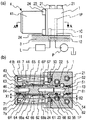
以下、本発明の電磁弁をオートマチックトランスミッションの油圧制御装置に適用した一実施の形態を図面に基づいて説明する。図1(a)において、電磁弁は、油圧制御装置のバルブボディ3に複数のネジ21によって取付けられるハウジング1と、該ハウジング1の左端部に固定されるソレノイド部4を有している。上記ハウジング1内には、流体流路として、油圧ポンプPよりバルブボディ3内を経て作動油が供給されるライン流路11と、油圧制御を行うクラッチやブレーキ等の負荷Lに連通するコントロール流路12が形成されている。また、ライン流路11の端部にはプレッシャポート1Pが、コントロール流路12の端部にはコントロールポート1Cが、それぞれ形成されている。
【0017】
上記ソレノイド部4は、図1(b)に示すように、略円筒状で軟磁性材よりなるヨーク41と、該ヨーク41内に保持される筒状コイル42とからなる。上記ヨーク41は、右端部外周の2箇所に切欠き41aを有し(図1(a))、上記ハウジング1の左端部に配設した、軟磁性材よりなる略円筒状のステイ22周りに嵌着される。そして、上記切欠き41aに固定プレート23を挿入し、ネジ24を螺挿することにより上記ステイ22とともに上記ハウジング1に固定される。上記ヨーク41の左端開口内には、上記ヨーク41に設けた肩部41bに当接せしめて、軟磁性材よりなるエンドプレート43が配設してあり(図1(b))、該エンドプレート43の外周縁は、上記ヨーク41の開口縁にて包かしめされている。
【0018】
図1(b)において、上記ハウジング1内には、図の左右方向に延びる第一の取付け穴たる取付け穴13が形成されており、該取付け穴13内に支持部材となるベース部材5が配設されている。ベース部材5は略円筒状で、軟磁性材よりなり、その内部を作動油の導入路51となしてある。該導入路51は右端部外周に形成した環状溝52を介して、その外周の上記プレッシャポート1Pに連通しており、ライン流路11より作動油が導入されるようになしてある。上記ベース部材5の左端部は、上記ハウジング1より突出して段付きに拡径しており、該拡径部内に、ベース部材5とともに支持部材を構成するシャフト6が嵌装固定されている。上記拡径部より突出する上記シャフト6の左半部は、上記ソレノイド部4の中空部内に延びている。
【0019】
上記シャフト6には、中間部外周に、流路切替えを行うためのプランジャ65が摺動自在に支持されている。上記シャフト6の左端部外周には、上記プランジャ65の左方への移動を規制する、ストッパ部たる円筒状の規制部材7が圧入固定もしくは溶接固定により一体に設けてある。この規制部材7は、上記エンドプレート43より右方に突出する筒状突部44内に形成される第二の取付け穴となる取付け穴45内に挿通保持されている。
【0020】
上記シャフト6の右端部内には、上記ベース部材5の導入路51に連通する導入路61が形成されている。該導入路61の左端部は、連通路62を介して上記シャフト6の外周に設けたプレッシャポート6Pに連通している。一方、上記エンドプレート43にはこれを貫通して外部に開口するリターン流路46が形成されており、上記シャフト6の左端部内には、このリターン流路46に連通するリターン流路63が形成されている。このリターン流路63の右端部は、連通路64を介して、上記シャフト6外周に設けたリターンポート6Rに連通している。
【0021】
図2(a)に示すように、上記プランジャ65は略円筒状で、その外周にスプリングストッパ65aとなる環状突部を有し、このスプリングストッパ65aと上記ベース部材5の間に配設したスプリング67により図の左方に付勢されている。また、上記シャフト6は、プレッシャポート6Pに隣接する部分をやや大径に形成してあり、上記プランジャ65の右方への移動を規制するストッパ部68となしてある。上記ソレノイド部4に通電しない図示の状態では、上記プランジャ65の右端と、上記ストッパ部68のエッジ部68aの間には隙間Gが形成され(図2(b))、該隙間Gを介して、上記プレッシャポート6Pと上記プランジャ65の周囲に形成される流路66とが連通する(図1(b))。この時、上記プランジャ65は、上記規制部材7のエッジ部7aに当接し、上記リターンポート6Rと上記流路66との間を遮断している。なお、上記流路66は、上記ベース部材5に形成した複数の溝53を介して上記ハウジング1内のコントロールポート1Cに連通している(図1(a)参照)。
【0022】
本発明においては、支持部材を構成する上記ベース部材5およびシャフト6と、上記プランジャ65、上記シャフト6と一体の上記規制部材7を、その他の構成部材に対し浮動支持する。すなわち、上記ベース部材5の端面と取付け穴13との間には空間が形成されており、ここに弾性部材たる弾性リング81が介設してある。また、上記ベース部材5の外周面と取付け穴13の内周面との間には、小間隙が形成されており、上記ベース部材5の外周面に設けた環状溝54、55に弾性部材たる弾性リング82、83を介設している。これにより、上記ベース部材5を上記ハウジング1に対し弾性的に支持し、両者の接触を防止するとともに、これらの間をシールしている。同様に、上記規制部材7は取付け穴45内に小間隙を有して配置され、上記規制部材7の端面と取付け穴45の間の空間には、弾性部材たる弾性リング84が、上記規制部材7の外周面に設けた環状溝71には弾性部材たる弾性リング85が介設してある。さらに、上記プランジャ65の左端部と上記筒状突部44の間、上記ベース部材5と上記ステー22との間にも、それぞれ所定の間隙X1、X2を形成して、両者が接触しないようにしている。
【0023】
なお、図2(a)に示すように、上記ベース部材5の、環状溝52を挟んで右側の径D1と左側の径D2が等しくなるように形成する。この時、プレッシャポート1Pより流入する作動油に対し左右の受圧面積が一致し、バランスする。同様に、上記流路66内の流体圧を受ける上記ベース部材5の径D3と上記シャフト6の径D4、規制部材7の径D5が等しくなるように形成する。この時、プレッシャ圧、コントロール圧に対し、上下、左右方向にバランスする。
【0024】
上記電磁弁の作動を図1により説明する。上記ソレノイド部4のコイル42に外部より一定周波数のパルス列(ON−OFF信号)を入力することにより、上記プランジャ65は、上記ストッパ部68のエッジ部68aと上記規制部材7のエッジ部7aの間を摺動する。これにより、ライン流路11より、プレッシャポート1P、導入路51、61、プレッシャポート6P、上記流路66を経て、上記コントールポート1Cよりコントロール流路12に作動油が供給され、あるいは、上記コントールポート1Cより上記流路66、上記リターンポート6R、上記リターン流路63、46を経て作動油が排出されて、コントロール圧を制御する。コントロール圧は、駆動周期に対するON時間の比(デューティ比)により決定される。
【0025】
この時、上記電磁弁の作動に伴い、上記プランジャ65が上記シャフト6と上記規制部材7を加振するが、これら部材および上記シャフト6と一体の上記ベース部材5は、弾性リング81〜85により浮動支持されているので、より外側の他の構成部材に対する加振力は減衰される。すなわち、上記ハウジング1や上記ソレノイド部4の振動は、従来に比し、大幅に低減し、従って、ヨーク41の周囲に存在する作動油を介して外部に放射される騒音も大きく低減する。また、上記ハウジング1を介してバルブボディ3やトランスミッションケースに伝達される振動も効果的に低減される。
【0026】
また、上記ベース部材5と上記シャフト6および上記規制部材7は、プレッシャ圧、コントロール圧に対し、上下、左右方向にバランスしているので、流体圧によってこれら部材が押され、弾性リング81〜85が圧縮されてその振動減衰効果が小さくなることを防止できる。
【0027】
ここで、弾性部材である弾性リングの設置位置は、必ずしも上記第1の実施の形態の位置に限定されるものではなく、加振源およびこれに直接加振される部材が、より外側の他の構成部材に対し浮動支持される構成となっていればよい。その一例を図3に本発明の第2の実施の形態として示す。
【0028】
本実施の形態では、図3のように、支持部材である上記シャフト6の左端部と取付け穴45の間の空間に、弾性リングを介設せず、その代わりに、上記コイル42の内周面に沿って内方に突出する環状突起42aと、ベース部材5の外周に設けた段部5aとの間に、弾性リング80を介設する。この時、上記取付け穴45とともに上記コイル42の内周部全体が第二の取付け穴として機能する。弾性リング84を除く弾性リング81、82、83、85の設置位置およびその他の構成は上記第1の実施の形態と同様である。
【0029】
上記取付け穴45が形成されるエンドプレート43は、左端面が外部に露出して放射面となるため、これと加振源との間に介在する部材を極力少なくすることが、振動伝達を低減する上で望ましい。特に、上記シャフト6の左端部周りに設けられ上記プランジャ65に直接加振される上記規制部材7の加振方向の端面(左端面)と、上記エンドプレート43との間に弾性部材が介在しないようにすることで、効果的に振動伝達を低減することができる。また、外部に露出しないコイル42の内周面と支持部材となるベース部材5の間に介設した弾性リング80は、上記第1の実施の形態における上記弾性リング84と同様の機能を有し、上記ベース部材5およびこれと一体の上記シャフト6、上記規制部材7は、第二の取付け穴内において確実に浮動支持する。かくして、上記ソレノイド部4外表面からの振動伝達をさらに低減して、振動や騒音の発生を防止することができる。
【0030】
図4に本発明の第3の実施の形態を示す。本実施の形態の基本構成は上記第1の実施の形態と同様であり、以下、相違点について主に説明する。本実施の形態において、ヨーク41の内部には、所定の間隙を有して筒状コイル42が配設されており、上記ヨーク41の左端面41cと、これに対向する上記コイル42の端面との間には環状の弾性部材86が介設されている。上記ヨーク41の右端部は、上記スティ22の外側に所定の間隙を有して配置され、固定プレート23とネジ24により、上記ハウジング1に支持せしめられている。
【0031】
ここで、上記ヨーク41は、上記固定プレート23が挿通される切欠き41aの幅を、上記固定プレート23の厚みより大きく形成して、上記固定プレート23と上記切欠き41aとの間に空隙を形成し、さらに上記固定プレート23の右端面と上記切欠き41aとの間に弾性部材87を介設する。しかして、上記ヨーク41は、上記弾性部材86、87により、上記コイル42および上記ハウジングに対し、金属接触することなく、浮動支持される。
【0032】
また、本実施の形態では、上記図1におけるエンドプレート43に代えて、キャップ部材9を設けている。このキャップ部材9は、内部を上記規制部材7を保持する取付け穴93とする磁性材よりなる筒状部材91と、上記プランジャ65の周囲を覆う非磁性材よりなる筒体92を有し、筒体92の右端部は、上記ステイ22の左端に突設した筒状部22a周りに接合固定されている。上記キャップ部材9の左端面は、上記ヨーク41の左端面41c中央部の開口より、外部に臨んでいる。
【0033】
本実施の形態では、特に放射面積が大きい上記ソレノイド部4のヨーク41を他の構成部材に対し浮動支持する。これにより、上記プランジャ65が上記シャフト6と上記規制部材7を加振しても、その振動が上記ヨーク41に伝達されることが抑制され、ヨーク41周囲の作動油を介して外部に騒音が放射されることを抑制できる。また、デューティ作動中には、上記プランジャ65の周囲に油圧脈動が発生し、これが上記ヨーク41を振動させる大きな原因となっていたが、本実施の形態では、上記プランジャ65を上記シャフト6および上記規制部材7とともに、キャップ部材9で覆ったので、油圧脈動がより外側に伝播することを防止し、より効果的に振動を低減できる。
【0034】
なお、本実施の形態において、上記第1の実施の形態のように、上記規制部材7および上記ベース部材5を、その取付け穴93、13に対し、弾性部材を介して浮動支持することもできる。この時、上記ハウジング1側への振動の伝達がさらに抑制され、振動低減効果が向上する。
【0035】
図5に本発明の参考例を示す。本参考例の基本構成は上記第1の実施の形態と同様であり、以下、相違点について主に説明する。図5(a)に示すように、本参考例では、上記各実施の形態におけるベース部材5を有しておらず、上記シャフト6は、上記ハウジング1に固定される略円筒状のステイ22´内に嵌挿固定される。上記ハウジング1には、図略のライン流路に連通するプレッシャポート14が形成され、該プレッシャポート14は導入路15を介して上記シャフト6の導入路61に連通している。上記プランジャ65を左方に付勢するスプリング67は、上記プランジャ65外周のスプリングストッパ65aと上記ステイ22´との間に配設される。
【0036】
本参考例では、上記プランジャ65の左方への移動を規制するストッパ部たる規制部材7を、エンドプレート43に設けた取付け穴45内に、所定の間隙Laを有して挿通配置し、両者の間を弾性リング85にてシールする。上記シャフト6の左端面と取付け穴45の対向面の間、上記プランジャ65とその外方に位置する部材の間にも空間が形成されており、加振源およびこれに直接加振される部材が他の部材と接触しないようにしてある。
【0037】
上記構成によれば、放射面となる上記エンドプレート43およびヨーク41が、上記シャフト6および規制部材7と直接接触しておらず、特に、加振方向である上記シャフト6の左端面と取付け穴45の間には、何も介在していないので、上記プランジャ65が上記シャフト6および規制部材7を加振しても、上記エンドプレート43およびヨーク41に伝達される振動は大きく低減する。
【0038】
図5(b)は、本参考例による振動低減効果を示すもので、本参考例の構成(本参考品)と、規制部材7と取付け穴45との間に間隙Laを設けない構成(比較品)の、電流on、off時の音圧を比較したものである。図のように、電流off側、すなわち上記プランジャ65が上記スプリング67の付勢力により規制部材7に当接する場合において、明らかな振動伝達防止効果が見られ、規制部材7とその周囲の取付け穴45との間に間隙を設けることで、振動伝達を低減できることがわかる。このように、本参考例によれば、加振源およびこれに直接加振される部材と、その外側の構成部材との間に間隙を設けるという比較的簡単な構成で、放射面への振動伝達を抑制し、外部への放射を防止することができる。
【図面の簡単な説明】
【図1】 本発明の第1の実施の形態を示し、(a)は電磁弁を油圧制御装置のバルブボディに取付けた状態を示す図、(b)は(a)のA−A線断面図である。
【図2】 (a)はプランジャおよび規制部材の拡大断面図、(b)は(a)の部分拡大断面図である。
【図3】 本発明の第2の実施の形態を示す電磁弁の全体断面図である。
【図4】 本発明の第3の実施の形態を示す電磁弁の全体断面図である。
【図5】 本発明の参考例を示し、(a)は電磁弁の全体断面図、(b)は参考例の効果を示す図である。
【図6】 従来の電磁弁の全体断面図である。
【図7】 従来の電磁弁を適用したオートマチックトランスミッションの全体構成概略図である。[0001]
BACKGROUND OF THE INVENTION
The present invention relates to a structure for reducing noise in an electromagnetic valve for hydraulic control, and more particularly to an electromagnetic valve structure suitable as a duty-driven electromagnetic valve.
[0002]
[Prior art]
In a device having an electromagnetic valve for hydraulic control, such as a hydraulic control transmission, reducing vibration and noise caused by the operation of the electromagnetic valve is a major issue. As a structure for reducing the noise of the electromagnetic valve, there is one disclosed in Japanese Utility Model Publication No. 3-8850, which is shown in FIG. In FIG. 6, the
[0003]
[Problems to be solved by the invention]
According to the above configuration, the vibration generated when the
[0004]
As a structure for reducing the noise generated from the solenoid valve body, in Japanese Patent Laid-Open No. 60-1486, rubber cushions as stoppers are arranged at both ends of a spool that is driven by a solenoid and performs flow path switching. It is disclosed to prevent contact noise during spool operation. However, in this configuration, since the stopper is formed of a rubber cushion, the durability cannot be said to be sufficient as a duty-driving solenoid valve that repeats the ON-OFF operation at high speed.
[0005]
Therefore, an object of the present invention is to reduce vibrations generated by the operation of the solenoid valve, particularly noise radiated from the solenoid portion of the solenoid valve to its surroundings, and is sufficient as a solenoid valve for duty drive. It is an object of the present invention to provide an electromagnetic valve structure having excellent durability.
[0006]
[Means for Solving the Problems]
In order to solve the above problems, a solenoid valve according to a first aspect of the present invention includes a housing attached to the valve body, a flow path of a working fluid formed in the housing, and a plurality of fluid ports communicating with the flow path. A solenoid portion comprising a yoke fixed to the housing and a cylindrical coil held in the yoke; a plunger that is driven by the solenoid portion to switch communication and blocking between the plurality of fluid ports; and the plunger And a pair of stopper portions that respectively oppose both end portions of the plunger and restrict the movement range thereof. The support member is provided integrally with the pair of stopper portions, one end side of the support member integrated with the pair of stopper portions is in a first mounting hole provided in the housing, and the other end side is the cylinder. In the second mounting hole provided in the inner peripheral portion of the coil-like coil, they are arranged with a gap, and are supported floating by an elastic member.
[0007]
In the above-described configuration, the support member, the pair of stopper portions, and the plunger are supported in a floating manner with respect to the other component members positioned outside these. Therefore, even when the support member and the pair of stopper portions are vibrated when the plunger is driven, the vibration is greatly attenuated by the elastic member, and vibration transmission to the solenoid portion and the housing is suppressed. . In this way, vibration transmission to the yoke having a large radiation area is achieved by floating the portion where vibration is generated and the portion directly excited inside the solenoid valve with respect to the outer constituent members. The vibration can be prevented from being radiated as noise to the outside of the solenoid valve. Further, since vibration transmission to the housing is also reduced, generation of vibration and noise can be greatly reduced as compared with the conventional case. Moreover, since the member to be vibrated by the plunger is not an elastic member, the durability is also excellent.
[0008]
The elastic member is formed of, for example, an elastic ring, and the first or second mounting hole is provided between the both end surfaces of the support member and the first or second mounting hole, and at a plurality of locations on the outer peripheral surface of the support member. (Claim 2). At this time, if the insertion position of the elastic ring is appropriately selected, and if it serves as a sealing member of the supporting member and the other constituent members provided with the pair of stopper portions, the number of parts is not greatly increased. In addition, an excellent noise reduction effect can be obtained.
[0009]
Alternatively, the elastic member may be configured not to be interposed between an end surface of the support member on the cylindrical coil side and a component member on the outer surface of the solenoid portion serving as a radiation surface (Claim 3). . By not interposing an elastic member between the surface to be the radiation surface and the support member, in particular, the cylindrical coil side end surface of the support member located in the excitation direction, the outer surface of the solenoid unit to be the radiation surface Vibration transmission can be further reduced, and the effect of preventing generation of vibration and noise is high.
[0010]
Specifically, the elastic member in the configuration of
[0011]
Further, in the support member and the pair of stopper portions, if the opposing pressure receiving surfaces that receive the fluid pressure have the same area for each fluid port pressure (Claim 5), the elastic member is caused by the fluid pressure. It is possible to prevent the vibration reduction effect of the decrease.
[0012]
Instead of the configuration of
[0013]
At this time, the support member is integrally provided with the pair of stopper portions, one end thereof is held in a mounting hole provided in the housing, and the other end protruding from the housing is fixed to the housing. It is good also as a structure covered with the member (Claim 7). The vibration of the yoke is caused mainly by pressure pulsation generated around the plunger by driving the plunger. Therefore, the yoke and the portion directly excited by the plunger are covered with the cap member, thereby The transmission of vibration to can be made smaller.
[0016]
DETAILED DESCRIPTION OF THE INVENTION
Hereinafter, an embodiment in which a solenoid valve of the present invention is applied to a hydraulic control device for an automatic transmission will be described with reference to the drawings. In FIG. 1A, the electromagnetic valve has a
[0017]
As shown in FIG. 1 (b), the
[0018]
In FIG. 1B, a mounting
[0019]
A
[0020]
An
[0021]
As shown in FIG. 2 (a), the
[0022]
In the present invention, the
[0023]
As shown in FIG. 2A, the
[0024]
The operation of the electromagnetic valve will be described with reference to FIG. By inputting a pulse train (ON-OFF signal) having a constant frequency to the
[0025]
At this time, with the operation of the electromagnetic valve, the
[0026]
Further, since the
[0027]
Here, the installation position of the elastic ring, which is an elastic member, is not necessarily limited to the position of the first embodiment. What is necessary is just to become the structure supported by floating with respect to the structural member of. An example thereof is shown in FIG. 3 as a second embodiment of the present invention.
[0028]
In the present embodiment, as shown in FIG. 3, an elastic ring is not provided in the space between the left end portion of the
[0029]
Since the left end surface of the
[0030]
FIG. 4 shows a third embodiment of the present invention. The basic configuration of the present embodiment is the same as that of the first embodiment, and differences will be mainly described below. In the present embodiment, a
[0031]
Here, the
[0032]
In the present embodiment, a
[0033]
In the present embodiment, the
[0034]
In the present embodiment, as in the first embodiment, the restricting
[0035]
FIG. 5 shows a reference example of the present invention. The basic configuration of this reference example is the same as that of the first embodiment, and differences will be mainly described below. As shown in FIG. 5A, in this reference example , the
[0036]
In this reference example , the regulating
[0037]
According to the above configuration, the
[0038]
FIG. 5 (b), shows the vibration reduction effect by the present embodiment, the configuration (comparative without the clearance La between the configuration of the present embodiment (the present reference product), the
[Brief description of the drawings]
1A and 1B show a first embodiment of the present invention, in which FIG. 1A is a diagram showing a state where an electromagnetic valve is attached to a valve body of a hydraulic control device, and FIG. 1B is a cross-sectional view taken along line AA in FIG. FIG.
2A is an enlarged sectional view of a plunger and a regulating member, and FIG. 2B is a partially enlarged sectional view of FIG.
FIG. 3 is an overall cross-sectional view of a solenoid valve showing a second embodiment of the present invention.
FIG. 4 is an overall sectional view of a solenoid valve showing a third embodiment of the present invention.
5A and 5B show a reference example of the present invention, in which FIG. 5A is an overall cross-sectional view of a solenoid valve, and FIG. 5B is a diagram showing the effect of the reference example .
FIG. 6 is an overall sectional view of a conventional solenoid valve.
FIG. 7 is a schematic diagram of the overall configuration of an automatic transmission to which a conventional solenoid valve is applied.
Claims (7)
Priority Applications (1)
| Application Number | Priority Date | Filing Date | Title |
|---|---|---|---|
| JP05609898A JP4076262B2 (en) | 1997-08-25 | 1998-02-19 | solenoid valve |
Applications Claiming Priority (3)
| Application Number | Priority Date | Filing Date | Title |
|---|---|---|---|
| JP24475597 | 1997-08-25 | ||
| JP9-244755 | 1997-08-25 | ||
| JP05609898A JP4076262B2 (en) | 1997-08-25 | 1998-02-19 | solenoid valve |
Publications (2)
| Publication Number | Publication Date |
|---|---|
| JPH11132355A JPH11132355A (en) | 1999-05-21 |
| JP4076262B2 true JP4076262B2 (en) | 2008-04-16 |
Family
ID=26397025
Family Applications (1)
| Application Number | Title | Priority Date | Filing Date |
|---|---|---|---|
| JP05609898A Expired - Fee Related JP4076262B2 (en) | 1997-08-25 | 1998-02-19 | solenoid valve |
Country Status (1)
| Country | Link |
|---|---|
| JP (1) | JP4076262B2 (en) |
Families Citing this family (2)
| Publication number | Priority date | Publication date | Assignee | Title |
|---|---|---|---|---|
| JP5779019B2 (en) * | 2011-07-15 | 2015-09-16 | 川崎重工業株式会社 | Solenoid proportional control valve |
| JP2023023634A (en) * | 2021-08-05 | 2023-02-16 | イーグル工業株式会社 | solenoid valve |
-
1998
- 1998-02-19 JP JP05609898A patent/JP4076262B2/en not_active Expired - Fee Related
Also Published As
| Publication number | Publication date |
|---|---|
| JPH11132355A (en) | 1999-05-21 |
Similar Documents
| Publication | Publication Date | Title |
|---|---|---|
| US7523763B2 (en) | Three-port electromagnetic valve | |
| JP5013782B2 (en) | Active vibration damper | |
| JP2011256951A (en) | Normally closed solenoid valve device | |
| KR20010080906A (en) | Electromagnetic device, especially for an anti-slip hydraulic vehicle brake system | |
| JP2008175342A (en) | Fluid-filled engine mount | |
| JPH024833B2 (en) | ||
| JP4076262B2 (en) | solenoid valve | |
| JP2004150546A (en) | Engine mount | |
| JPH09280304A (en) | Liquid sealing type mount device | |
| US20080179798A1 (en) | Fluid filled type engine mount | |
| JPH05129131A (en) | Electromagnet for operating valve | |
| JP5069200B2 (en) | Vibration isolator | |
| JP4054932B2 (en) | Solenoid valve for fluid pressure control | |
| JP5038198B2 (en) | Fluid filled vibration isolator | |
| JP2004076945A (en) | Hydraulic mount | |
| JP4237521B2 (en) | Liquid-filled vibration isolator | |
| JP4173066B2 (en) | Vibration isolator | |
| JPH06137454A (en) | Solenoid valve | |
| JP4173085B2 (en) | Vibration isolator | |
| JPH10267072A (en) | Fluid sealed vibration isolating device | |
| JP2002227915A (en) | Vibration control equipment | |
| JPH1096443A (en) | Engine mounting roller stopper | |
| JP2009108880A (en) | Fluid filled vibration damping device | |
| JP3944885B2 (en) | Active liquid-filled vibration isolator | |
| JPH11344152A (en) | Solenoid valve |
Legal Events
| Date | Code | Title | Description |
|---|---|---|---|
| A621 | Written request for application examination |
Free format text: JAPANESE INTERMEDIATE CODE: A621 Effective date: 20040602 |
|
| A977 | Report on retrieval |
Free format text: JAPANESE INTERMEDIATE CODE: A971007 Effective date: 20070313 |
|
| A131 | Notification of reasons for refusal |
Free format text: JAPANESE INTERMEDIATE CODE: A131 Effective date: 20070327 |
|
| A521 | Written amendment |
Free format text: JAPANESE INTERMEDIATE CODE: A523 Effective date: 20070528 |
|
| TRDD | Decision of grant or rejection written | ||
| A01 | Written decision to grant a patent or to grant a registration (utility model) |
Free format text: JAPANESE INTERMEDIATE CODE: A01 Effective date: 20080129 |
|
| A61 | First payment of annual fees (during grant procedure) |
Free format text: JAPANESE INTERMEDIATE CODE: A61 Effective date: 20080129 |
|
| R150 | Certificate of patent or registration of utility model |
Free format text: JAPANESE INTERMEDIATE CODE: R150 |
|
| FPAY | Renewal fee payment (event date is renewal date of database) |
Free format text: PAYMENT UNTIL: 20110208 Year of fee payment: 3 |
|
| FPAY | Renewal fee payment (event date is renewal date of database) |
Free format text: PAYMENT UNTIL: 20120208 Year of fee payment: 4 |
|
| FPAY | Renewal fee payment (event date is renewal date of database) |
Free format text: PAYMENT UNTIL: 20130208 Year of fee payment: 5 |
|
| LAPS | Cancellation because of no payment of annual fees |