JP4073384B2 - Torque detection device - Google Patents
Torque detection device Download PDFInfo
- Publication number
- JP4073384B2 JP4073384B2 JP2003332511A JP2003332511A JP4073384B2 JP 4073384 B2 JP4073384 B2 JP 4073384B2 JP 2003332511 A JP2003332511 A JP 2003332511A JP 2003332511 A JP2003332511 A JP 2003332511A JP 4073384 B2 JP4073384 B2 JP 4073384B2
- Authority
- JP
- Japan
- Prior art keywords
- magnetic
- shaft
- torque
- permanent magnet
- magnetic flux
- Prior art date
- Legal status (The legal status is an assumption and is not a legal conclusion. Google has not performed a legal analysis and makes no representation as to the accuracy of the status listed.)
- Expired - Fee Related
Links
Images


Landscapes
- Power Steering Mechanism (AREA)
- Force Measurement Appropriate To Specific Purposes (AREA)
Description
本発明は、車両の電動パワーステアリング装置等に好適に使用され、連結軸により同軸に連結された第1軸及び第2軸と、第1軸に固設された永久磁石と、第2軸に固定され、永久磁石の磁界内に配置されて磁気回路を形成する複数の軟磁性体と、軟磁性体に発生した磁束を検出する検出器とを備え、第1軸又は第2軸にトルクが加えられたときに、検出器の出力に基づき、トルクを検出するトルク検出装置に関するものである。 The present invention is suitably used for an electric power steering device of a vehicle, and the like. The first shaft and the second shaft are coaxially connected by a connecting shaft, the permanent magnet fixed to the first shaft, and the second shaft. A plurality of soft magnetic bodies that are fixed and arranged in a magnetic field of a permanent magnet to form a magnetic circuit, and a detector that detects a magnetic flux generated in the soft magnetic body, and torque is applied to the first axis or the second axis. The present invention relates to a torque detection device that detects torque based on the output of a detector when added.
車両の舵取装置に、電動モータを駆動して操舵補助を行ない、運転者の負担を軽減するものがある。これは、操舵部材(ステアリングホイール、ハンドル)に繋がる入力軸と、ピニオン及びラック等により操向車輪に繋がる出力軸と、入力軸及び出力軸を連結する連結軸とを備え、連結軸に生じる捩れ角度によって、トルク検出装置が入力軸に加わる操舵トルクを検出し、検出した操舵トルク値に基づき、出力軸に連動する操舵補助用の電動モータを駆動制御するものである。 Some steering devices for vehicles reduce the burden on the driver by driving an electric motor to assist steering. This includes an input shaft connected to a steering member (steering wheel, steering wheel), an output shaft connected to a steering wheel by a pinion, a rack, and the like, and a connecting shaft that connects the input shaft and the output shaft. The torque detection device detects the steering torque applied to the input shaft based on the angle, and drives and controls the steering assist electric motor linked to the output shaft based on the detected steering torque value.
このような舵取装置のトルク検出装置には、従来、コイルを用いて回転位置を検出する磁気検知式レゾルバ、又は光の透過を検知する光学式エンコーダの検出装置等が使用されている。また、特許文献1には、トーションバーにより同軸に連結された入力軸及び出力軸と、入力軸に固設されたリング状の永久磁石と、出力軸に固定され、永久磁石の磁界内に配置されて磁気回路を形成する複数の軟磁性体からなる磁気ヨークと、磁気ヨークに発生した磁束を検出する磁気センサとを備え、入力軸にトルクが加えられたときに、磁気センサの出力に基づき、トルクを検出するトルクセンサが提案されている。
Conventionally, for such a torque detection device of a steering device, a magnetic detection type resolver that detects a rotational position using a coil, an optical encoder detection device that detects transmission of light, or the like is used. In
特許文献1には、また、トーションバーにより同軸に連結された入力軸及び出力軸と、入力軸に固設されたリング状の永久磁石と、出力軸に固定され、永久磁石の磁界内に配置されて磁気回路を形成する複数の軟磁性体からなる磁気ヨークと、磁気ヨークに磁気結合され、磁気ヨークからの磁束を誘導する複数の集磁リングと、集磁リングが誘導した磁束を検出する磁気センサとを備え、入力軸にトルクが加えられたときに、磁気センサの出力に基づき、トルクを検出するトルクセンサが提案されている。
上述したようなトルクセンサでは、製造時に、磁気ヨークと磁気センサとの高精度の位置決め、又は集磁リングと磁気センサとの高精度の位置決めが必要であるので、組み付けには細心の注意を払わなければならず、手間がかかり、生産性が低下するという問題がある。本発明は、上述したような事情に鑑みてなされたものであり、製造時に組み付けが容易で生産性が向上するトルク検出装置を提供することを目的とする。 The torque sensor as described above requires high-precision positioning between the magnetic yoke and the magnetic sensor or high-precision positioning between the magnetism collecting ring and the magnetic sensor at the time of manufacture. There is a problem that it takes time and labor and productivity is lowered. The present invention has been made in view of the above-described circumstances, and an object of the present invention is to provide a torque detection device that can be easily assembled at the time of manufacture and can improve productivity.
本発明に係るトルク検出装置は、連結軸により同軸に連結された第1軸及び第2軸と、該第1軸に固設された永久磁石と、前記第2軸に固定され、前記永久磁石の磁界内に配置されて磁気回路を形成する軟磁性体である2つの磁気ヨークと、該磁気ヨークに発生した磁束を検出する検出器とを備え、前記第1軸又は第2軸にトルクが加えられたときに、前記検出器の出力に基づき、前記トルクを検出すべくなしてあるトルク検出装置において、前記2つの磁気ヨークは、板状のリングに、その板面に垂直な一方向に延びる複数の二等辺三角形状の爪が等間隔に周設された2つの磁気ヨークであり、それぞれの爪が周方向に適当な間隔でずれるように対向する状態で、前記検出器と共に合成樹脂により円筒形状にモールドされて一体化されていることを特徴とする。 The torque detection device according to the present invention includes a first shaft and a second shaft that are coaxially coupled by a coupling shaft, a permanent magnet fixed to the first shaft, a fixed to the second shaft, and the permanent magnet Two magnetic yokes, which are soft magnetic bodies that are arranged in the magnetic field of the magnetic field, and a detector that detects the magnetic flux generated in the magnetic yoke, and torque is applied to the first axis or the second axis. In the torque detection device for detecting the torque based on the output of the detector when applied, the two magnetic yokes are arranged in a plate-shaped ring in one direction perpendicular to the plate surface. A plurality of isosceles triangular claws that extend are two magnetic yokes that are circumferentially arranged at equal intervals, and the respective claws are opposed to each other so as to be displaced at an appropriate interval in the circumferential direction. Molded into a cylindrical shape and integrated It is characterized in.
このトルク検出装置では、第1軸及び第2軸が連結軸により同軸に連結され、永久磁石が第1軸に固設されている。2つの磁気ヨークが、第2軸に固定され、永久磁石の磁界内に配置されて磁気回路を形成し、検出器が磁気ヨークに発生した磁束を検出し、第1軸又は第2軸にトルクが加えられたときに、検出器の出力に基づき、トルクを検出する。2つの磁気ヨークは、板状のリングに、その板面に垂直な一方向に延びる複数の二等辺三角形状の爪が等間隔に周設された2つの磁気ヨークであり、それぞれの爪が周方向に適当な間隔でずれるように対向する状態で、検出器と共に合成樹脂により円筒形状にモールドされて一体化されている。 In this torque detector, the first shaft and the second shaft are connected coaxially by a connecting shaft, and the permanent magnet is fixed to the first shaft. Two magnetic yokes are fixed to the second axis and arranged in the magnetic field of the permanent magnet to form a magnetic circuit. The detector detects the magnetic flux generated in the magnetic yoke , and torques the first axis or the second axis. Is applied, the torque is detected based on the output of the detector. The two magnetic yokes are two magnetic yokes in which a plurality of isosceles triangular claws extending in one direction perpendicular to the plate surface are provided at equal intervals on a plate-shaped ring, and each of the claws has a circumference. It is molded in a cylindrical shape with a synthetic resin and integrated with the detector in a state of being opposed so as to be displaced at an appropriate interval in the direction .
本発明に係るトルク検出装置によれば、磁気ヨークと磁気センサとの位置決め作業が不要となるので、製造時に組み付けが容易で生産性が向上するトルク検出装置を実現することが出来る。 According to the torque detection device of the present invention, the positioning operation between the magnetic yoke and the magnetic sensor is not necessary, and therefore a torque detection device that can be easily assembled and improved in productivity at the time of manufacture can be realized.
以下に、本発明をその実施の形態を示す図面に基づいて説明する。
(実施の形態)
図1は、本発明に係るトルク検出装置の実施の形態の構成を示す説明図であり、(a)は分解斜視図、(b)は縦断面図、(c)は横断面図である。このトルク検出装置は、入力軸1(第1軸)と出力軸2(第2軸)とを、細径のトーションバー3(連結軸)を介して同軸状に連結している。入力軸1及び出力軸2は、それぞれピン9によりトーションバー3に連結されている。
Hereinafter, the present invention will be described with reference to the drawings illustrating embodiments thereof.
(In the form state of implementation)
Figure 1 is an explanatory view showing a configuration in the form status of implementation of the torque detection device according to the present invention, (a) is a exploded perspective view, (b) is a longitudinal sectional view, (c) is a cross-sectional view . In this torque detector, an input shaft 1 (first shaft) and an output shaft 2 (second shaft) are coaxially connected via a small-diameter torsion bar 3 (connecting shaft). The
入力軸1には、24極(N,S極各12極)が周方向に等間隔で着磁された円筒形状の(24極)永久磁石5が、同軸に固設されている。出力軸2には、半径方向に適当な隙間を設けて永久磁石5を囲む円筒形状のヨーク4が、同軸に固設されている。ヨーク4は、図2に示すように、板状のリングに、その板面に垂直な一方向に延びる12個の二等辺三角形状の爪10が等間隔に周設された2つの磁気ヨーク4a,4b(軟磁性体)を備えている。2つの磁気ヨーク4a,4bは、それぞれの爪10が周方向に適当な間隔でずれるように対向する状態で、合成樹脂により円筒形状にモールドされている。
A cylindrical (24 pole)
磁気ヨーク4a,4bは、永久磁石5が形成する磁界内に配置されており、それらの間のギャップに生じる磁束を検出する1又は複数のホールIC6(ホール素子、検出器)が、ギャップに挿入された状態で、磁気ヨーク4a,4bと共に合成樹脂によりモールドされ一体化されている。ホールIC6は、図示しないハウジングに固定され、ホールIC6のリード線7は、図示しない基板に半田付けされ、ホールIC6が作動する為の電源を供給し、ホールIC6が検出した出力を得ている。磁気ヨーク4a,4bは、トルクが加えられない中立状態で、それぞれの爪10の先端が、永久磁石5のN極及びS極の境界を指すように配置される。
The
以下に、このような構成のトルク検出装置の動作を説明する。入力軸1又は出力軸2にトルクが加えられないとき、磁気ヨーク4a,4bの各爪10は、図3(b)に示すように、永久磁石5のN極及びS極に対向する面積が等しくなり、N極から入る磁束とS極へ出る磁束とが等しくなるので、磁気ヨーク4a及び磁気ヨーク4b間には磁束は生じない。
Below, operation | movement of the torque detection apparatus of such a structure is demonstrated. When no torque is applied to the
入力軸1又は出力軸2に一方向のトルクが加えられたとき、トーションバー3に捩れが生じて、磁気ヨーク4a,4bの各爪10及び永久磁石5の相対位置が変化する。このとき、例えば、図3(a)に示すように、磁気ヨーク4aの各爪10に対向する面積が、永久磁石5のN極の方がS極より大きくなり、N極から入る磁束の方がS極へ出る磁束より大きくなる。また、磁気ヨーク4bの各爪10に対向する面積が、永久磁石5のN極の方がS極より小さくなり、N極から入る磁束の方がS極へ出る磁束より小さくなる。その結果、磁気ヨーク4aから磁気ヨーク4bへの磁束が生じ、この磁束密度は、各爪10に対向するN極及びS極の面積の差が大きい程、大きくなる。
When a one-way torque is applied to the
一方、入力軸1又は出力軸2に他方向のトルクが加えられたとき、上記とは逆方向に、トーションバー3に捩れが生じて、磁気ヨーク4a,4bの各爪10及び永久磁石5の相対位置が変化する。このとき、例えば、図3(c)に示すように、磁気ヨーク4aの各爪10に対向する面積が、永久磁石5のN極の方がS極より小さくなり、N極から入る磁束の方がS極へ出る磁束より小さくなる。また、磁気ヨーク4bの各爪10に対向する面積が、永久磁石5のN極の方がS極より大きくなり、N極から入る磁束の方がS極へ出る磁束より大きくなる。その結果、磁気ヨーク4bから磁気ヨーク4aへの磁束が生じ、この磁束密度は、各爪10に対向するN極及びS極の面積の差が大きい程、大きくなる。
On the other hand, when a torque in the other direction is applied to the
上述した磁気ヨーク4a及び磁気ヨーク4b間のギャップに生じる磁束密度の変化を、トーションバー3の捩れ角である電気角−180〜180deg.(機械角−15〜15deg.)に対応させて図示すると、図3(d)に示すような正弦波状となる。実際に使用される範囲は、トーションバー3の剛性から、−90〜90deg.を超えることはなく、加えられたトルクに応じた磁束密度を検出することが出来る。つまり、検出した磁束密度に基づき、加えられたトルクを知ることが出来る。
The change in the magnetic flux density generated in the gap between the magnetic yoke 4a and the
(開示技術)
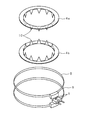
図4は、開示されるトルク検出装置の構成を示す説明図であり、(a)は分解斜視図、(b)は縦断面図、(c)は横断面図である。このトルク検出装置は、磁気ヨーク4a,4bにそれぞれ磁気結合され、磁気ヨーク4a,4bからの磁束をそれぞれ誘導する2つの集磁リング8,8(補助軟磁性体)を備えている。集磁リング8,8は、図5に示すように、平行に配置され、互いに他部分より近接する平板状の部分を有し、その近接する部分の隙間に、1又は複数のホールIC6が挿入されている。
( Disclosure technology )
Figure 4 is an explanatory diagram showing a configuration of a torque detecting apparatus disclosed, (a) an exploded perspective view, the (b) is a longitudinal sectional view, (c) is a cross-sectional view. The torque detector includes two magnetic
集磁リング8,8及びホールIC6は、上述した状態で、合成樹脂によりモールドされ一体化されている。これとは別に、磁気ヨーク4a,4bも、実施の形態と同様の形態で、合成樹脂によりモールドされ一体化されて、ヨーク41を形成している。その他の構成は、実施の形態で説明したトルク検出装置の構成と同様であるので、説明を省略する。
In the state described above, the magnetism collecting rings 8 and 8 and the
このような構成のトルク検出装置では、磁気ヨーク4a,4bに生じた磁束は、集磁リング8,8によりそれぞれ誘導され、誘導された磁束は、集磁リング8,8の互いに近接する部分に優先的に集まり、ホールIC6により検出される。集磁リング8,8により、ホールIC6は、磁気ヨーク4a,4bの全周で発生する磁束密度の平均を検出することが出来る。その他の動作は、実施の形態で説明したトルク検出装置の動作と同様であるので、説明を省略する。
In the torque detector having such a configuration, the magnetic fluxes generated in the
[図1] 本発明に係るトルク検出装置の実施の形態の構成を示す説明図である。
[図2] 図1に示すトルク検出装置の磁気ヨーク及びホールICを示す分解斜視図である。
[図3] 本発明に係るトルク検出装置の実施の形態の動作を示す説明図である。
[図4] 開示されるトルク検出装置の構成を示す説明図である。
[図5] 図4に示すトルク検出装置の磁気ヨーク、集磁リング及びホールICを示す分解斜視図である。
FIG. 1 is an explanatory diagram showing a configuration of an embodiment of a torque detection device according to the present invention.
2 is an exploded perspective view showing a magnetic yoke and a Hall IC of the torque detector shown in FIG.
[FIG. 3] It is explanatory drawing which shows operation | movement of embodiment of the torque detection apparatus based on this invention.
Is an explanatory diagram showing the configuration of [4] the disclosed torque detector.
[5] The magnetic yoke of the torque detection device shown in FIG. 4 is an exploded perspective view showing a magnetic flux collector rings and Hall IC.
1 入力軸(第1軸)
2 出力軸(第2軸)
3 トーションバー(連結軸)
4 ヨーク
4a,4b 磁気ヨーク(軟磁性体)
5 (24極)永久磁石
6 ホールIC(ホール素子、検出器)
7 リード線
8 集磁リング(補助軟磁性体)
10 爪
1 Input shaft (first axis)
2 Output shaft (second shaft)
3 Torsion bar (connection shaft)
4
5 (24 poles)
7 Lead
10 nails
Claims (1)
前記2つの磁気ヨークは、板状のリングに、その板面に垂直な一方向に延びる複数の二等辺三角形状の爪が等間隔に周設された2つの磁気ヨークであり、それぞれの爪が周方向に適当な間隔でずれるように対向する状態で、前記検出器と共に合成樹脂により円筒形状にモールドされて一体化されていることを特徴とするトルク検出装置。 A first shaft and a second shaft connected coaxially by a connecting shaft, a permanent magnet fixed to the first shaft, and a magnetic circuit fixed to the second shaft and disposed in the magnetic field of the permanent magnet And two detectors for detecting magnetic flux generated in the magnetic yoke, and when the torque is applied to the first shaft or the second shaft, the detector In the torque detection device adapted to detect the torque based on the output of
The two magnetic yokes are two magnetic yokes in which a plurality of isosceles triangular claws extending in one direction perpendicular to the plate surface are provided around a plate-like ring at equal intervals. A torque detector characterized by being integrated in a cylindrical shape with a synthetic resin together with the detector in a state of being opposed so as to be displaced at an appropriate interval in the circumferential direction.
Priority Applications (1)
| Application Number | Priority Date | Filing Date | Title |
|---|---|---|---|
| JP2003332511A JP4073384B2 (en) | 2003-09-24 | 2003-09-24 | Torque detection device |
Applications Claiming Priority (1)
| Application Number | Priority Date | Filing Date | Title |
|---|---|---|---|
| JP2003332511A JP4073384B2 (en) | 2003-09-24 | 2003-09-24 | Torque detection device |
Publications (2)
| Publication Number | Publication Date |
|---|---|
| JP2005098821A JP2005098821A (en) | 2005-04-14 |
| JP4073384B2 true JP4073384B2 (en) | 2008-04-09 |
Family
ID=34460796
Family Applications (1)
| Application Number | Title | Priority Date | Filing Date |
|---|---|---|---|
| JP2003332511A Expired - Fee Related JP4073384B2 (en) | 2003-09-24 | 2003-09-24 | Torque detection device |
Country Status (1)
| Country | Link |
|---|---|
| JP (1) | JP4073384B2 (en) |
Cited By (1)
| Publication number | Priority date | Publication date | Assignee | Title |
|---|---|---|---|---|
| US7936249B2 (en) | 2001-11-26 | 2011-05-03 | Inventio Ag | System for security control and/or transportation of persons with an elevator installation, method of operating this system, and method of retrofitting an elevator installation with this system |
Families Citing this family (4)
| Publication number | Priority date | Publication date | Assignee | Title |
|---|---|---|---|---|
| EP1746011A4 (en) * | 2004-04-06 | 2007-11-07 | Nsk Ltd | Electric power steering device |
| EP1621447B1 (en) | 2004-07-29 | 2013-09-25 | Jtekt Corporation | Torque detecting apparatus and electric power steering apparatus |
| JP4997474B2 (en) * | 2007-03-29 | 2012-08-08 | 株式会社ジェイテクト | Torque detection device |
| KR20090002543U (en) | 2007-09-10 | 2009-03-13 | 엘지이노텍 주식회사 | Apparatus for detecting torque |
-
2003
- 2003-09-24 JP JP2003332511A patent/JP4073384B2/en not_active Expired - Fee Related
Cited By (1)
| Publication number | Priority date | Publication date | Assignee | Title |
|---|---|---|---|---|
| US7936249B2 (en) | 2001-11-26 | 2011-05-03 | Inventio Ag | System for security control and/or transportation of persons with an elevator installation, method of operating this system, and method of retrofitting an elevator installation with this system |
Also Published As
| Publication number | Publication date |
|---|---|
| JP2005098821A (en) | 2005-04-14 |
Similar Documents
| Publication | Publication Date | Title |
|---|---|---|
| US6928888B2 (en) | Torque sensor for detecting a shaft torque | |
| EP1621447B1 (en) | Torque detecting apparatus and electric power steering apparatus | |
| JP2006038767A (en) | Device for detecting torque | |
| JP6311926B2 (en) | Torque sensor and electric power steering device | |
| JP5440754B2 (en) | Torque detector, electric power steering apparatus, and method of manufacturing torque detector | |
| EP1630534B1 (en) | Torque detecting apparatus | |
| US20040074316A1 (en) | Torque sensor | |
| JP4822681B2 (en) | Torque detection device | |
| JP2004020527A (en) | Torque sensor | |
| JP5071407B2 (en) | Torque sensor and electric power steering apparatus using the same | |
| JP3861778B2 (en) | Torque sensor, electric power steering apparatus using the torque sensor, and method for manufacturing the electric power steering apparatus | |
| JP2009192248A (en) | Torque detector | |
| JP4073384B2 (en) | Torque detection device | |
| JP4656851B2 (en) | Torque detection device | |
| JP2005265581A (en) | Torque detection apparatus | |
| JP4036806B2 (en) | Torque detection device | |
| JP2005069994A (en) | Device for detecting torque | |
| JP4030945B2 (en) | Torque detection device | |
| JP2009020064A (en) | Torque sensor and electric power steering device | |
| JP4030944B2 (en) | Torque detection device | |
| JP2005265593A (en) | Torque detecting apparatus | |
| JP2009092463A (en) | Torque detection apparatus, its manufacturing method, and electric power steering system | |
| JP2005265580A (en) | Torque detector | |
| JP2006064578A (en) | Torque detecting device | |
| JP2006064587A (en) | Torque detection apparatus and electric power steering system |
Legal Events
| Date | Code | Title | Description |
|---|---|---|---|
| A521 | Request for written amendment filed |
Free format text: JAPANESE INTERMEDIATE CODE: A523 Effective date: 20050523 |
|
| A711 | Notification of change in applicant |
Free format text: JAPANESE INTERMEDIATE CODE: A711 Effective date: 20050523 |
|
| A621 | Written request for application examination |
Free format text: JAPANESE INTERMEDIATE CODE: A621 Effective date: 20060821 |
|
| A711 | Notification of change in applicant |
Free format text: JAPANESE INTERMEDIATE CODE: A711 Effective date: 20060829 |
|
| A977 | Report on retrieval |
Free format text: JAPANESE INTERMEDIATE CODE: A971007 Effective date: 20070725 |
|
| A131 | Notification of reasons for refusal |
Free format text: JAPANESE INTERMEDIATE CODE: A131 Effective date: 20070731 |
|
| A521 | Request for written amendment filed |
Free format text: JAPANESE INTERMEDIATE CODE: A523 Effective date: 20071001 |
|
| A131 | Notification of reasons for refusal |
Free format text: JAPANESE INTERMEDIATE CODE: A131 Effective date: 20071030 |
|
| A521 | Request for written amendment filed |
Free format text: JAPANESE INTERMEDIATE CODE: A523 Effective date: 20071226 |
|
| TRDD | Decision of grant or rejection written | ||
| A01 | Written decision to grant a patent or to grant a registration (utility model) |
Free format text: JAPANESE INTERMEDIATE CODE: A01 Effective date: 20080122 |
|
| A61 | First payment of annual fees (during grant procedure) |
Free format text: JAPANESE INTERMEDIATE CODE: A61 Effective date: 20080122 |
|
| FPAY | Renewal fee payment (event date is renewal date of database) |
Free format text: PAYMENT UNTIL: 20110201 Year of fee payment: 3 |
|
| R150 | Certificate of patent or registration of utility model |
Free format text: JAPANESE INTERMEDIATE CODE: R150 Ref document number: 4073384 Country of ref document: JP Free format text: JAPANESE INTERMEDIATE CODE: R150 |
|
| FPAY | Renewal fee payment (event date is renewal date of database) |
Free format text: PAYMENT UNTIL: 20120201 Year of fee payment: 4 |
|
| FPAY | Renewal fee payment (event date is renewal date of database) |
Free format text: PAYMENT UNTIL: 20130201 Year of fee payment: 5 |
|
| FPAY | Renewal fee payment (event date is renewal date of database) |
Free format text: PAYMENT UNTIL: 20130201 Year of fee payment: 5 |
|
| FPAY | Renewal fee payment (event date is renewal date of database) |
Free format text: PAYMENT UNTIL: 20140201 Year of fee payment: 6 |
|
| LAPS | Cancellation because of no payment of annual fees |