JP4072712B2 - Cylinder valve - Google Patents
Cylinder valve Download PDFInfo
- Publication number
- JP4072712B2 JP4072712B2 JP2002167670A JP2002167670A JP4072712B2 JP 4072712 B2 JP4072712 B2 JP 4072712B2 JP 2002167670 A JP2002167670 A JP 2002167670A JP 2002167670 A JP2002167670 A JP 2002167670A JP 4072712 B2 JP4072712 B2 JP 4072712B2
- Authority
- JP
- Japan
- Prior art keywords
- valve
- valve body
- opening
- water
- cylinder valve
- Prior art date
- Legal status (The legal status is an assumption and is not a legal conclusion. Google has not performed a legal analysis and makes no representation as to the accuracy of the status listed.)
- Expired - Fee Related
Links
Images


Landscapes
- Taps Or Cocks (AREA)
Description
【0001】
【発明の属する技術分野】
本発明は、シリンダバルブに関する。
【0002】
【従来の技術】
従来、図18に示すように、開口を有する弁ガイドに、開口を有する弁体を内装して、弁体に連結された操作部を回転させることで弁体を回転させて、弁体の開口と弁ガイドの開口とを重ね合わせたり、ずらしたりすることで通水・止水を行なうシリンダバルブが提案されている。
そして、弁ガイドは、下面部に操作部と弁体とを挿入する挿入孔を設け、上面部に挿入孔から挿入した操作部のつまみを貫通する貫通孔と操作部の回転を規制するストッパー102とを設けている。
そして、挿入孔から操作部と弁体を挿入して弁ガイド内に装着した後、挿入孔を塞ぎ蓋100で覆って、挿入孔から弁体が飛び出さないようにしている。
【0003】
【発明が解決しようとする課題】
しかしながら、従来のシリンダバルブにおいては、塞ぎ蓋100で覆っているため、部品点数が多くなってしまっており、軸方向の寸法も長くなってしまっていた。
また、他の従来のシリンダバルブにおいては、抜け止めピン101をつまみに設けた溝にかしめて嵌め込んでいるため、操作部の回転に伴い、抜け止めピン101も同時に回っていた。
そのため、この抜け止めピン101の回転領域には、操作部の回転を規制するストッパー102を形成することができなかった。
したがって、弁ガイドの径方向の寸法が大きくなってしまうといった問題が生じていた。
なお、図18に示す従来シリンダバルブは、上述する塞ぎ蓋100と抜け止めピン101の両方を図示している。
そこで、本発明では上記の問題点を解決するため、コンパクトで操作性のよいシリンダバルブを提供することを目的とする。
【0004】
【課題を解決するための手段】
上記課題を解決すべく、本発明の請求項1では、側面に開口を有する弁ガイドに、側面に開口を有する弁体を内装して、この弁体に連結された操作部を回転させることで前記弁体を回転させて、前記弁体の開口と前記弁ガイドの開口とを重ね合わせたり、ずらしたりすることで通水と止水を行なうシリンダバルブであって、前記弁ガイドは、下面部に前記操作部と前記弁体とを挿入する挿入孔を設け、上面部に挿入孔から挿入した前記操作部のつまみを貫通する貫通孔と、前記操作部の回転を規制するストッパーとを設け、
前記つまみには溝部を形成して、前記貫通孔よりも外径が大きい抜け止めピンを前記溝部に嵌めるとともに、前記抜け止めピンをC形状として、前記溝部に装着したときに前記抜け止めピンのC形状の開部が前記ストッパーに重なり合うように配置していることを特徴とするシリンダバルブとした。
【0005】
このように構成したため、シリンダバルブを組み立てた後に操作部が貫通孔から外れるおそれがなく、かつ、ストッパーと抜け止めピンを重なり合うように配置しているため、特に径方向の寸法をコンパクトにすることができる。
【0006】
本発明の請求項2では、前記抜け止めピンは、前記操作部の回転動作と同時に抜け止めピンが回転しないように前記溝部に緩く嵌まっていることを特徴とする請求項1に記載のシリンダバルブとした。
【0007】
このように構成したため、操作部を回転すると抜け止めピンが同時に回転してストッパーに抜け止めピンが衝突して操作部の操作性が低下するようなことがない。
したがって、コンパクトで操作性のよいシリンダバルブを提供することができる。
【0008】
本発明の請求項3では、前記操作部の基部外周には、前記弁体保持用の突起部を形成し、この突起部を前記弁体の一側端部に形成した保持孔に嵌合係止して、前記操作部と前記弁体とを前記弁ガイドの挿入孔から挿入して前記弁ガイド内に装着したことを特徴とする請求項1または2に記載のシリンダバルブとした。
【0009】
これにより、従来のシリンダバルブのように塞ぎ蓋を用いずに済み、部品点数を低減することができる。そのため、塞ぎ蓋で覆わないですむため、軸方向の長さを小さく抑えることができ、コンパクトにすることができる。
【0010】
【発明の実施の形態】
以下に図面を参照して本発明をより具体的に説明する。
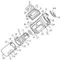
図1は、本発明のシリンダバルブ1の斜視図である。
図2は、図1のシリンダバルブ1の展開図である。
図3は、図1のシリンダバルブ1の断面斜視図である。
図4は、図1のシリンダバルブ1の弁体4と操作部3とを側方から見た図である。
図5は、図1のシリンダバルブ1を操作部3のつまみ11のある側から見た図である。
図6は、弁体4の開口4Aの開状態から閉状態になる遷移を示す図である。
図7および図8は、本発明のシリンダバルブ1を止水栓28として用いた場合の通水状態を示す断面図である。
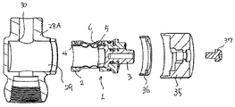
図9は、図8の止水栓28の展開断面図である。
図10は、図8の止水栓28における止水栓本体28Aにシリンダバルブ1を組み込むときの部分拡大図である。
図11は、ハンドル35を外した状態の止水栓28の外観斜視図である。
図12は、本発明のシリンダバルブ1を用いたツーハンドル式の湯水混合栓38である。
図13は、図12の湯水混合栓38の断面図である。
図14は、スパウト41の先端に本発明のシリンダバルブ1を用いた単水栓39である。
図15は、図14の単水栓39の断面図である。
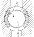
図16は、本発明のシリンダバルブを止水栓本体や湯水混合栓本体などに組み込んだ場合の断面図である。
図17は、従来のシリンダバルブを止水栓本体や湯水混合栓本体などに組み込んだ場合の断面図である。
図18は、従来のシリンダバルブの断面図である。
【0011】
図1乃至図3に示すように、本発明のシリンダバルブ1は、弁ガイド2と操作部3と弁体4とシール部材5と押え部材6とから主構成されている。
そして、このシリンダバルブ1は、開口2Aを有する弁ガイド2に、開口4Aを有する弁体4を内装して、弁体4に連結された操作部3を回転させることで弁体4を回転させて、弁体4の開口4Aと弁ガイド2の開口2Aとを重ね合わせたり、ずらしたりすることで通水・止水を行なうものである。
【0012】
以下に各構成要素と各構成要素の組立てについて説明する。
弁ガイド2は、PPS(ポリフェニレンサルファイド)などの合成樹脂にて成形されている。そして、その形状は円筒形状をしており、下面部には操作部3と弁体4とを挿入する挿入孔7を設けており、上面部には挿入孔7から挿入した操作部3のつまみ11を貫通する貫通孔8を設けている。
なお、挿入孔7は、弁ガイド2の内径と同径である。
また、貫通孔8は、弁ガイド2の内径よりも小さい径であり、操作部3の基部13が貫通孔8を貫通しないように構成されている。そして、つまみ11を貫通孔8に貫通させ、かつ、操作部3の基部13とつまみ11との間に形成した外周溝9にOリング10を装着して操作部3と弁ガイド2との水密性を保持しており、貫通孔8からの漏水を防止している。
【0013】
また、つまみ11には溝部12を形成して、貫通孔8よりも外径が大きい抜け止めピン14をこの溝部12に嵌めることで、組立て後、操作部3のつまみ11が貫通孔8 から抜けないようにしている。
なお、図5に示すように、この抜け止めピン14は、C形状をしており、溝部12に装着したときにC 形状の開部14Aが弁ガイド2のストッパー15に重なり合うように配置している。このようにすることで、シリンダバルブ1全体(特にシリンダバルブ1の径方向の寸法)をよりコンパクトにすることが可能となる。
なお、このストッパー15は、操作部3の回転角度を規制するためのものである。具体的には、操作部3に装着するハンドル35に設けた突起(図示せず)がこのストッパー15に当接することで、バルブの開閉角度を規制している。
なお、このときに抜け止めピン14が溝部12に緩く嵌まっているので、操作部3の回転動作と同時に抜け止めピン14が回転しない。そのため、操作部3を回転すると抜け止めピン14が同時に回転して、ストッパー15に抜け止めピン14が衝突して操作部3の操作性が低下するようなことがない。
また、ストッパーの形状は、同心円で同角(鋭角)の大小の円弧(計2 つ)とそれら両端を通る2 つの半径から囲まれてなる略扇形状とすることが好ましい。
これにより操作部の回転を規制するのに、ストッパーの半径方向の面で当接させて、当接面積を大きくとることができるので、確実に回転を規制することができる。
【0014】
また、弁ガイド2の側面には対向するように通水用の開口2Aが設けられている。
そして、一方の開口2A側のみに、シール部材5を側方から取り付けている。さらにこのシール部材5の開口5Aに押え部材6を設けている。
この押え部材6を設けることで、通水方向をシール部材5の開口5Aから弁体4内に流れる方向だけでなく、弁体4内からシール部材5の開口5Aに流れる逆方向の通水においても、このシリンダバルブ1を用いることができる。
つまり、この押え部材6を用いることで、一方の弁ガイド2の開口2A側のみにシール部材5を設ければ、弁体4内からシール部材5の開口5Aに流れる通水使用においても、シール部材5が弁ガイド2から外れることがない。
そして、止水時に確実に水密性を保つことができる。
上述するように押え部材6を設けることで、一方の開口2A側のみにシール部材5を側方から取り付けるだけでよいので、部品点数を低減できる。また、コンパクト化が容易になる。
【0015】
また、シリンダバルブ1を組立てた後、このシリンダバルブ1を湯水混合栓本体38Aや止水栓本体28Aなどに組み付けて利用することができる。そのため、シリンダバルブ1の輸送時や組付け工程時に、シール部材5や押え部材6が弁ガイド2から容易に外れないようにする必要がある。
そこで、図2に示すように、シール部材5の裏面外周には保持凸部16が形成されており、弁ガイド2の開口2Aの外周側面部を一段窪ませて窪み部18を形成し、さらにその外周に保持凹部17を形成している。そして、このシール部材5の保持凸部16が弁ガイド2の保持凹部17に嵌合するようにシール部材5を弁ガイド2の一段窪ませた窪み部18に取付けることで、シール部材5が弁ガイド2から容易に外れないようにしている。
また、図3に示すように、シール部材5に押え部材6を嵌め込んで、シール部材5の開口5Aの内周における一部もしくは全周に設けた押え突起部19により、押え部材6を容易に外れないように押えることができる。
なお、押え部材6をシール部材5から取外す場合は、図1に示す押え部材6の外周に形成した凹部20にマイナスドライバーを引っ掛けて容易に取外すことができる。
また、図3に示すように押え部材6の開口6Aの弁体側内周端21には、Rを付けて湾曲面として通水を滑らかにするようにしている。
【0016】
弁体4は、ステンレスなどの金属にて形成されている。そして、図2、4に示すように、その形状は円筒形状をしており、その側面に開口4Aを有している。
特にステンレスとすることで、通水中に混入していた異物が弁体4と弁ガイド2との間に入り込んでその異物によって操作性が悪くなることはない。一方、もしもこの弁体4を合成樹脂にて成形した場合は、通水に異物が混入していると、弁体4と弁ガイド2との間に入り込み弁体4に異物がくい込んでしまいその異物が抵抗となって操作性を低下してしまうおそれがある。
【0017】
弁体4の側面の開口4Aは、湯水を通水するための開口4Aであり、対向する側面にそれぞれ設けられている。
また、この開口4Aは、各側面の上下方向に開口4Aを複数有している。
また、開口4Aの端部は湾曲形状として穴あけ加工を容易にしている。
また、各一側面に設けた開口4Aは、それぞれ弁体の回転方向と同方向の長さを異にしている。
図4では、上側に位置している開口4Aの長さLを下側に位置している開口4Aの長さlよりも長くしている。これは、操作部3を操作して弁体4を開状態から閉状態にするときに急速に閉状態にならないようにするためである。つまり図6に示すように、弁体4の開口4Aと弁ガイド2との重なり合わせることで通水される開口領域が、徐々に狭めることができるのである。そのため、ウォーターハンマーを発生するおそれを低減することができる。
また、特に高給水圧の地域においては、このように周方向の長さを異にすることで、初期の少量の流量調整が行ないやすいといった効果も奏する。
また、特に、開口4Aの長さは両端ともに長くするようにしておくとよい。開閉のための操作部3の回転方向を右回りとしたときでも左回りとしたときでも、上述するウォーターハンマーの発生を低減したり、高給水圧の地域において少量の流量調整ができるという効果を常に奏することができるからである。たとえば、図12に示すようなツーハンドル式の湯水混合栓38などにこのシリンダバルブ1を利用する場合に効果を奏する。
【0018】
次に、弁体4と操作部3との連結について図2,4に基づき説明する。
弁体4の一端部には位置出し凹部23を対向するように形成している。そして、操作部3の基部13外周に形成した位置出し凸部24にこの位置出し凹部23を嵌め込む。そうすることで操作部3の回転に伴なって弁体4を回転させることができる。
【0019】
また、操作部3の基部13外周には更に弁体保持用の突起部25を形成し、弁体4の一側端部に形成した保持孔26に嵌合係止するようにしている。
特に、操作部3は合成樹脂にて成形されているので、基部13の内側を肉厚としておく。そして、スレンレスなどの金属製の弁体4を嵌合係止するときに操作部3の基部13を撓ませるのではなくて、弁体4側を撓ませるようにすることが好ましい。
その理由は、樹脂を撓ませて、弁体4と嵌合係止させた場合、長期使用により樹脂が劣化して、嵌合力が弱くなり、ウォーターハンマーなどの衝撃により操作部3と弁体4との嵌合係止が外れてしまうおそれがあるからである。
そのため、樹脂である操作部3の基部13を撓ませるのではなく、長期使用により劣化しにくいステンレスなどの金属製の弁体4側を撓ませるようにすることが好ましい。
このような構成にすることで、特に、図13に示すように、弁体4の下端開口27を通水路として使用している場合に操作部3との嵌合係止が外れて弁体4が弁ガイド2から抜け出てしまうおそれがなくなり、長期使用においても高品質を保つことができるのである。
【0020】
次に、このシリンダバルブ1の通水状態・止水状態について説明する。
図7は、弁体4が半開きのときの通水状態を示している。
この場合、押え部材6によりシール部材5が押えられているため、通水の勢いによってシール部材5が捲れあがることもない。そのため、弁体4を回転させて止水したときにシール部材5と弁体4によって確実に水密性を保つことができる。
また、押え部材6の開口6Aの弁体4側外周端21には、Rを付けて湾曲面としている。そのため、通水抵抗を抑えて滑らかに通水することができる。
図16に基づき水圧がシール部材5にどのように掛かるかをより詳しく説明する。
図に示すようにシール部材5を設けた側の開口2A、5A、6Aを上流側に配置した場合、シール部材5の隆起部31に水圧が掛かる。そして、シール部材5を下側に押しやる力(矢印A)が生じるが押え部材6を設けることで、シール部材5が歪むことを抑制することができる。
また、隆起部31の開口5A側の隆起面は、開口面5aをそのまま延設して設けているため、上流側の隆起面に水が入り込むことがなく、シール部材5下側に押しやる力が掛かることをさらに抑制することができる。
このように構成することで、シール部材5の端部が歪んで、弁体4を回転させたときに弁ガイド2と弁体4とでそのシール部材5の端部を挟んでしまうことがなく、長期に亘り、水密性を維持することができる。
また、シール部材5を設けた側の開口2A、5A、6Aを下流側に配置した場合(図の通水方向とは逆方向とした場合)、弁ガイド2の外周の隙間に水が廻り込み、止水時にシール部材5の隆起部31に水圧が掛かる(一点鎖線の矢印B)。しかしながら、押え部材6を設けているため、隆起部31に水圧が掛かってシール部材6が開口5A側に変形しようとしても押え部材6により変形することを阻止することができる。そのため、長期に亘り、シール部材6の形状が変形することなく、水密性を維持することができるのである。
【0021】
次に、本発明のシリンダバルブ1を止水栓28として利用する場合について図7乃至10に基づき説明する。シール部材5の開口5Aの側端部には隆起部31を形成している。
そして、この隆起部31により、通水路の水密性を保つことができる。
では、組み付けについて以下に説明する。
図8に示すように、止水栓本体28Aの側方に設けた取付穴29からシリンダバルブ1を挿入する。
このとき、図10に示すようにシール部材5と止水栓本体28Aとが擦れ合って取り付けられる。特に止水栓本体28Aに設けられた通水路端部30に引っかかってシール部材5がずれないようにするために、隆起部31の傾斜は、開口5Aの反対側の隆起面31Aを開口5A側の隆起面31Bよりもなだらかな隆起面としている。
特に、開口5Aの反対側の隆起面31Aは、隆起角度を鋭角(より好ましくは45度以下)としてなだらかな隆起面としている。
この隆起部31と止水栓本体28Aの取付穴29の内側とによって水密性を保つことができる。
また、隆起部31の開口5A側の隆起面31Bを急にする。特に、より好ましくはこの隆起部31の開口5A側の隆起面31Aを、開口5Aの端面をそのまま延設させて垂直な隆起面とすることにより、通水時に水圧が掛かったとしてもシール部材5が捲れあがるおそれを低減できる。なお、本発明においては押え部材6をさらに設けることで、シール部材5の捲れ上がりをより抑えることができる。
そして、図8に示すように押え蓋36で止水栓本体28Aの取付穴29を覆って固定する。さらに、操作部3のつまみ11にハンドル35を取付けてネジ37によりつまみ11とハンドル35とを固定する。
【0022】
また、図8に示すように、弁ガイド2の操作部3側の外周に溝部32を形成しておき、その溝部32にOリング33を装着して止水栓本体28Aとシリンダバルブ1との水密性を保持する。これにより、取付穴29からの漏水を防止することができる。
なお、弁ガイド2には、貫通孔8(操作部3)側の外周側端部に爪部34が設けられている。
そして、この爪部34が止水栓本体28Aなどの取付け部分の凹部に嵌り込むように組み込まれる。これにより、操作部3を操作して回転したとしても、弁ガイド2は爪部34によって回転を規制されるので、同時に回転されることはない。
また、シリンダバルブ1を止水栓本体28Aから取外す場合には、図11に示すように、爪部34にマイナスドライバーを引っ掛けて容易に取外すことができる。特にシリンダバルブ1をコンパクト化した場合、手でつまみ11をつまんで止水栓本体28Aからシリンダバルブ1を引っ張り出すことは非常に困難となるため、この爪部34を設けておくことで、シリンダバルブ1を取り外してメンテナンスをしやすくなるのである。
なお、この爪部34は、口の字形状に突設してもよいが、図1、図11に示すように下側(挿入孔側)を開放したコの字形状に突設することが好ましい。コの字形状とすることで、取外す方向の部分が肉厚にすることができるので、マイナスドライバーで引っ掛けて取外すときに、欠けるおそれがなくなる。
なお、この止水栓28は、シリンダバルブ1の側面に設けた開口2Aから他側面に設けた開口2Aをシリンダバルブ1の通水経路としている。
【0023】
次に、本発明のシリンダバルブ1を湯水混合栓38として利用する場合について説明する。
図12に示すように、この湯水混合栓38は、筒状の湯水混合栓本体38Aの両端から本発明のシリンダバルブ1をそれぞれ装着して、各シリンダバルブ1によって給湯管40および給水管39からの供給される湯水の流量調整を行ない、適温の湯水をスパウト41から吐水する構成になっている。
このシリンダバルブ1では、弁体4と操作部3とを上述したように嵌合係止させることで、ウォーターハンマーなどの衝撃が通水路内に発生しても、弁体4が操作部3から外れてしまうようなことはない。また、このシリンダバルブ1は、操作部3を早く操作しても通水路である弁体4の側面に設けた開口4Aが急激に閉まらないように、周方向の長さを異にした開口4Aを複数設けている。
なお、この湯水混合栓38は、シリンダバルブ1の側面に設けた開口4A(シール部材5、押え部材6を設ける側の開口4A)から弁体4の下端開口27をシリンダバルブ1の通水経路としている。
【0024】
次に、本発明のシリンダバルブ1を単水栓39として利用する場合について説明する。
図14に示すように、単水洗のスパウト41先端部分の側方にこのシリンダバルブ1を内蔵して、ハンドル35によって通水・止水を行う。そしてスパウト41先端の吐水口40から吐水される。
図15には、シリンダバルブ1を構成するシール部材5と押え部材6が、一次側(上流側)に位置するように設けられる。そして、この単水栓39は、シリンダバルブ1の側面に設けた開口2Aから他側面に設けた開口2Aをシリンダバルブ1の通水経路としている。
シリンダバルブ1は、コンパクト化することができたため、スパウト41の外観径を変えずにスパウト41の通水路中にこのシリンダバルブ1を組み付けることができる。そのため、従来のシリンダバルブを組み込んだものに比べて、外観性を大幅に向上させることができる。
【0025】
【発明の効果】
以上の構成とすることで、コンパクトで操作性のよいシリンダバルブを提供することができる。
【図面の簡単な説明】
【図1】 本件発明の一実施の形態である本発明のシリンダバルブの斜視図を示す。
【図2】 図1のシリンダバルブの展開図である。
【図3】 図1のシリンダバルブの断面斜視図である。
【図4】 図1のシリンダバルブの弁体と操作部とを側方から見た図である。
【図5】 図1のシリンダバルブをつまみのある側から見た図である。
【図6】弁体の開口の開状態から閉状態になる遷移を示す図である。
【図7】 本発明のシリンダバルブを止水栓として用いた場合の通水状態を示す断面図である。
【図8】 本発明のシリンダバルブを止水栓として用いた場合の通水状態を示す断面図である。
【図9】 図8の止水栓の展開断面図である。
【図10】 図8の止水栓における止水栓本体にシリンダバルブを組み込むときの部分拡大図である。
【図11】 ハンドル35を外した状態の止水栓28の外観斜視図である。
【図12】 本発明のシリンダバルブを用いたツーハンドル式の湯水混合栓である。
【図13】 図12の湯水混合栓の断面図である。
【図14】 スパウトの先端に本発明のシリンダバルブを用いた単水栓である。
【図15】 図14の単水栓の断面図である。
【図16】 本発明のシリンダバルブを止水栓本体や湯水混合栓本体などに組み込んだ場合の断面図である。
【図17】 従来のシリンダバルブを止水栓本体や湯水混合栓本体などに組み込んだ場合の断面図である。
【図18】 従来のシリンダバルブの断面図である。
【符号の説明】
1 シリンダバルブ
2 弁ガイド
2A 弁ガイドの開口
3 操作部
4 弁体
4A 弁体の開口
5 シール部材
5A シール部材の開口
6 押え部材
6A 押え部材の開口
7 挿入孔
8 貫通孔
9 外周溝
10 Oリング
11 つまみ
12 溝部
13 基部
14 抜け止めピン
14A 抜け止めピンの開部
15 ストッパー
16 保持凸部
17 保持凹部
18 弁ガイドの一段窪ませた部分
19 押え突起部
20 押え部材の凹部
21 押え部材の弁体側外周端
22 弁体の開口端部
23 位置出し凹部
24 位置出し凸部
25 弁体保持用の突起部
26 保持孔
27 弁体の下端開口
28 止水栓
28A 止水栓本体
29 取付穴
30 通水路端部
31 隆起部
32 弁ガイドの外周の溝
33 Oリング
34 爪部
35 ハンドル
36 押え蓋
37 ビス
38 湯水混合栓
39 給水管
40 給湯管
41 スパウト
39 単水栓
40 吐水口[0001]
BACKGROUND OF THE INVENTION
The present invention relates to a cylinder valve.
[0002]
[Prior art]
Conventionally, as shown in FIG. 18, a valve body having an opening is internally provided in a valve guide having an opening, and the valve body is rotated by rotating an operation unit connected to the valve body, thereby opening the valve body. There has been proposed a cylinder valve that allows water to flow and stop by overlapping or shifting the opening of the valve guide.
The valve guide is provided with an insertion hole for inserting the operation portion and the valve body in the lower surface portion, and a
Then, after the operating portion and the valve body are inserted from the insertion hole and mounted in the valve guide, the insertion hole is closed and covered with the
[0003]
[Problems to be solved by the invention]
However, since the conventional cylinder valve is covered with the
In other conventional cylinder valves, since the
For this reason, the
Therefore, the problem that the dimension of the diameter direction of a valve guide will become large has arisen.
The conventional cylinder valve shown in FIG. 18 shows both the
Accordingly, in order to solve the above-described problems, an object of the present invention is to provide a compact and easy-to-operate cylinder valve.
[0004]
[Means for Solving the Problems]
In order to solve the above-mentioned problem, in
A groove portion is formed in the knob, and a retaining pin having an outer diameter larger than that of the through hole is fitted into the groove portion, and the retaining pin is formed in a C shape so that when the retaining pin is attached to the groove portion, The cylinder valve is characterized in that the C-shaped opening is arranged so as to overlap the stopper.
[0005]
With this configuration, there is no risk that the operating part will come out of the through hole after the cylinder valve is assembled, and the stopper and retaining pin are arranged so as to overlap each other. Can do.
[0006]
The cylinder according to
[0007]
With this configuration, when the operation unit is rotated, the retaining pin does not rotate at the same time, and the retaining pin does not collide with the stopper and the operability of the operating unit is not deteriorated.
Therefore, it is possible to provide a compact and good operability cylinder valve.
[0008]
According to a third aspect of the present invention, a projection for holding the valve body is formed on the outer periphery of the base of the operation portion, and the projection is fitted into a holding hole formed at one end of the valve body. The cylinder valve according to claim 1 or 2, wherein the operation portion and the valve body are inserted through an insertion hole of the valve guide and mounted in the valve guide.
[0009]
Thereby, it is not necessary to use a closing lid like a conventional cylinder valve, and the number of parts can be reduced. Therefore, since it is not necessary to cover it with a closing lid, the length in the axial direction can be kept small, and it can be made compact.
[ 0010 ]
DETAILED DESCRIPTION OF THE INVENTION
Hereinafter, the present invention will be described more specifically with reference to the drawings.
FIG. 1 is a perspective view of a
FIG. 2 is a development view of the
FIG. 3 is a cross-sectional perspective view of the
4 is a side view of the
FIG. 5 is a view of the
FIG. 6 is a diagram illustrating a transition from the open state of the opening 4A of the
7 and 8 are cross-sectional views showing a water passage state when the
FIG. 9 is a developed cross-sectional view of the
FIG. 10 is a partially enlarged view when the
FIG. 11 is an external perspective view of the
FIG. 12 shows a two-handle type hot and cold
FIG. 13 is a cross-sectional view of the hot and
FIG. 14 shows a
FIG. 15 is a cross-sectional view of the
FIG. 16 is a cross-sectional view when the cylinder valve of the present invention is incorporated in a stop cock main body, a hot water / mixture stopper main body or the like.
FIG. 17 is a cross-sectional view when a conventional cylinder valve is incorporated in a stop cock main body or a hot and cold mixing plug main body.
FIG. 18 is a cross-sectional view of a conventional cylinder valve.
[ 0011 ]
As shown in FIGS. 1 to 3, the
The
[ 0012 ]
Hereinafter, each component and assembly of each component will be described.
The
The
Further, the through
[ 0013 ]
Further, a
As shown in FIG. 5, the retaining
The
At this time, since the retaining
Moreover, it is preferable that the shape of the stopper is a substantially fan shape surrounded by concentric circles (two in total) having the same angle (acute angle) and two radii passing through both ends.
As a result, the rotation of the operation unit can be restricted by making contact with the radial surface of the stopper to increase the contact area, so that the rotation can be reliably controlled.
[ 0014 ]
Further, a
And the sealing
By providing the
That is, if the
And watertightness can be reliably maintained at the time of water stop.
By providing the
[ 0015 ]
In addition, after the
Therefore, as shown in FIG. 2, a holding
Further, as shown in FIG. 3, the
When the
Further, as shown in FIG. 3, the valve body side inner
[ 0016 ]
The
By using stainless steel in particular, the foreign matter mixed in the water does not enter between the
[ 0017 ]
The
Further, the
Further, the end of the
Further, the
In FIG. 4, the length L of the
In particular, in an area with a high water supply pressure, by making the lengths in the circumferential direction different in this way, there is an effect that an initial small amount of flow rate can be easily adjusted.
In particular, the length of the
[ 0018 ]
Next, the connection between the
A
[ 0019 ]
Further, a
In particular, since the
The reason is that when the resin is bent and engaged with the
Therefore, it is preferable not to bend the
With such a configuration, particularly, as shown in FIG. 13, when the lower end opening 27 of the
[ 0020 ]
Next, the water flow state / water stop state of the
FIG. 7 shows a water flow state when the
In this case, since the
Further, the
Based on FIG. 16, how the water pressure is applied to the
As shown in the drawing, when the
In addition, since the raised surface on the
With this configuration, the end of the
In addition, when the
[ 0021 ]
Next, the case where the
The raised
The assembly will be described below.
As shown in FIG. 8, the
At this time, as shown in FIG. 10, the
In particular, the raised surface 31A on the opposite side of the
Watertightness can be maintained by the raised
Further, the raised surface 31B on the
Then, as shown in FIG. 8, the
[ 0022 ]
Further, as shown in FIG. 8, a
The
And this nail | claw
Further, when the
In addition, although this nail | claw
The
[ 0023 ]
Next, the case where the
As shown in FIG. 12, the hot and cold
In the
The hot and cold
[ 0024 ]
Next, the case where the
As shown in FIG. 14, the
In FIG. 15, the
Since the
[ 0025 ]
【The invention's effect】
By setting it as the above structure, a compact and good operability cylinder valve can be provided.
[Brief description of the drawings]
FIG. 1 is a perspective view of a cylinder valve of the present invention which is an embodiment of the present invention.
FIG. 2 is a development view of the cylinder valve of FIG. 1;
FIG. 3 is a cross-sectional perspective view of the cylinder valve of FIG. 1;
4 is a side view of a valve body and an operation unit of the cylinder valve of FIG. 1; FIG.
FIG. 5 is a view of the cylinder valve of FIG. 1 as viewed from the side with a knob.
FIG. 6 is a diagram illustrating a transition from an open state of the valve body to a closed state.
FIG. 7 is a cross-sectional view showing a water flow state when the cylinder valve of the present invention is used as a water stop cock.
FIG. 8 is a cross-sectional view showing a water flow state when the cylinder valve of the present invention is used as a water stop cock.
9 is a developed cross-sectional view of the water stop cock of FIG.
FIG. 10 is a partially enlarged view when a cylinder valve is incorporated in the stop cock main body of the stop cock of FIG. 8;
11 is an external perspective view of the
FIG. 12 is a two-handle type hot / cold mixing tap using the cylinder valve of the present invention.
13 is a cross-sectional view of the hot and cold water mixing tap of FIG.
FIG. 14 is a single water tap using the cylinder valve of the present invention at the tip of a spout.
15 is a cross-sectional view of the single water tap of FIG.
FIG. 16 is a cross-sectional view when the cylinder valve of the present invention is incorporated in a stop cock main body, a hot and cold water mixing plug main body, or the like.
FIG. 17 is a cross-sectional view when a conventional cylinder valve is incorporated in a stop cock main body or a hot and cold water mixing plug main body.
FIG. 18 is a cross-sectional view of a conventional cylinder valve.
[Explanation of symbols]
DESCRIPTION OF
Claims (3)
前記つまみには溝部を形成して、前記貫通孔よりも外径が大きい抜け止めピンを前記溝部に嵌めるとともに、前記抜け止めピンをC形状として、前記溝部に装着したときに前記抜け止めピンのC形状の開部が前記ストッパーに重なり合うように配置していることを特徴とするシリンダバルブ。A valve guide having an opening on the side surface is provided with a valve body having an opening on the side surface, and the valve body is rotated by rotating an operation unit connected to the valve body, so that the opening of the valve body and the valve body A cylinder valve that performs water flow and water stop by overlapping or shifting the opening of the valve guide, wherein the valve guide has an insertion hole for inserting the operation portion and the valve body in a lower surface portion. Providing a through hole penetrating the knob of the operation part inserted from the insertion hole on the upper surface part, and a stopper for restricting the rotation of the operation part,
A groove portion is formed in the knob, and a retaining pin having an outer diameter larger than that of the through hole is fitted into the groove portion, and the retaining pin is formed in a C shape so that when the retaining pin is attached to the groove portion, A cylinder valve characterized in that a C-shaped opening is arranged so as to overlap the stopper.
Priority Applications (1)
| Application Number | Priority Date | Filing Date | Title |
|---|---|---|---|
| JP2002167670A JP4072712B2 (en) | 2002-06-07 | 2002-06-07 | Cylinder valve |
Applications Claiming Priority (1)
| Application Number | Priority Date | Filing Date | Title |
|---|---|---|---|
| JP2002167670A JP4072712B2 (en) | 2002-06-07 | 2002-06-07 | Cylinder valve |
Related Child Applications (1)
| Application Number | Title | Priority Date | Filing Date |
|---|---|---|---|
| JP2007267658A Division JP4556984B2 (en) | 2007-10-15 | 2007-10-15 | Cylinder valve |
Publications (3)
| Publication Number | Publication Date |
|---|---|
| JP2004011815A JP2004011815A (en) | 2004-01-15 |
| JP2004011815A5 JP2004011815A5 (en) | 2005-09-15 |
| JP4072712B2 true JP4072712B2 (en) | 2008-04-09 |
Family
ID=30434850
Family Applications (1)
| Application Number | Title | Priority Date | Filing Date |
|---|---|---|---|
| JP2002167670A Expired - Fee Related JP4072712B2 (en) | 2002-06-07 | 2002-06-07 | Cylinder valve |
Country Status (1)
| Country | Link |
|---|---|
| JP (1) | JP4072712B2 (en) |
Families Citing this family (1)
| Publication number | Priority date | Publication date | Assignee | Title |
|---|---|---|---|---|
| KR100944387B1 (en) | 2007-08-06 | 2010-02-26 | 박강훈 | Cylinder Type Valve |
-
2002
- 2002-06-07 JP JP2002167670A patent/JP4072712B2/en not_active Expired - Fee Related
Also Published As
| Publication number | Publication date |
|---|---|
| JP2004011815A (en) | 2004-01-15 |
Similar Documents
| Publication | Publication Date | Title |
|---|---|---|
| JP4706981B2 (en) | Cylinder valve | |
| US8517055B2 (en) | Valve cartridge with lobular key | |
| JP4062726B2 (en) | Cylinder valve | |
| JP4045865B2 (en) | Cylinder valve and hot water / water mixing tap using this cylinder valve | |
| JP4556984B2 (en) | Cylinder valve | |
| KR830002827B1 (en) | Faucet valve with early shut off | |
| JP4072712B2 (en) | Cylinder valve | |
| US20140326342A1 (en) | Single-lever mixing cartridge | |
| US20060202149A1 (en) | Cylindrical plug valve | |
| JP4232450B2 (en) | Cylinder valve and water supply device provided with cylinder valve | |
| JP4975463B2 (en) | Cylinder type valve | |
| KR101973251B1 (en) | A ball valve | |
| JP3993014B2 (en) | Switching valve | |
| JP2739467B2 (en) | Single lever mixer tap | |
| KR200356297Y1 (en) | The connecting structure between a shower-body and a shower-hose | |
| KR200400995Y1 (en) | The gas safety dual valve. | |
| US6161581A (en) | Valve device for water distribution purposes | |
| KR200383416Y1 (en) | Secret ostructure of ball valve consisted of metal ball seat | |
| JP5747278B2 (en) | Mixer tap | |
| US6732756B2 (en) | Adapter for valve and manifold assembly | |
| JP3308144B2 (en) | Single lever mixer tap | |
| JPS5934763Y2 (en) | hot water mixing faucet | |
| JPS605109Y2 (en) | Water faucet | |
| KR200344248Y1 (en) | Changing apparatus of water flow | |
| JPS6329008Y2 (en) |
Legal Events
| Date | Code | Title | Description |
|---|---|---|---|
| A521 | Written amendment |
Free format text: JAPANESE INTERMEDIATE CODE: A523 Effective date: 20050329 |
|
| A621 | Written request for application examination |
Free format text: JAPANESE INTERMEDIATE CODE: A621 Effective date: 20050329 |
|
| A977 | Report on retrieval |
Free format text: JAPANESE INTERMEDIATE CODE: A971007 Effective date: 20070823 |
|
| A131 | Notification of reasons for refusal |
Free format text: JAPANESE INTERMEDIATE CODE: A131 Effective date: 20070827 |
|
| A521 | Written amendment |
Free format text: JAPANESE INTERMEDIATE CODE: A523 Effective date: 20071015 |
|
| TRDD | Decision of grant or rejection written | ||
| A01 | Written decision to grant a patent or to grant a registration (utility model) |
Free format text: JAPANESE INTERMEDIATE CODE: A01 Effective date: 20071227 |
|
| A61 | First payment of annual fees (during grant procedure) |
Free format text: JAPANESE INTERMEDIATE CODE: A61 Effective date: 20080109 |
|
| FPAY | Renewal fee payment (event date is renewal date of database) |
Free format text: PAYMENT UNTIL: 20110201 Year of fee payment: 3 |
|
| R150 | Certificate of patent or registration of utility model |
Free format text: JAPANESE INTERMEDIATE CODE: R150 Ref document number: 4072712 Country of ref document: JP Free format text: JAPANESE INTERMEDIATE CODE: R150 |
|
| FPAY | Renewal fee payment (event date is renewal date of database) |
Free format text: PAYMENT UNTIL: 20120201 Year of fee payment: 4 |
|
| FPAY | Renewal fee payment (event date is renewal date of database) |
Free format text: PAYMENT UNTIL: 20130201 Year of fee payment: 5 |
|
| FPAY | Renewal fee payment (event date is renewal date of database) |
Free format text: PAYMENT UNTIL: 20130201 Year of fee payment: 5 |
|
| FPAY | Renewal fee payment (event date is renewal date of database) |
Free format text: PAYMENT UNTIL: 20140201 Year of fee payment: 6 |
|
| LAPS | Cancellation because of no payment of annual fees |