JP4072616B2 - Kitchen grease filter - Google Patents
Kitchen grease filter Download PDFInfo
- Publication number
- JP4072616B2 JP4072616B2 JP2002071024A JP2002071024A JP4072616B2 JP 4072616 B2 JP4072616 B2 JP 4072616B2 JP 2002071024 A JP2002071024 A JP 2002071024A JP 2002071024 A JP2002071024 A JP 2002071024A JP 4072616 B2 JP4072616 B2 JP 4072616B2
- Authority
- JP
- Japan
- Prior art keywords
- metal
- net
- coil wire
- filter
- small mesh
- Prior art date
- Legal status (The legal status is an assumption and is not a legal conclusion. Google has not performed a legal analysis and makes no representation as to the accuracy of the status listed.)
- Expired - Fee Related
Links
Images


Landscapes
- Ventilation (AREA)
- Filtering Materials (AREA)
- Filtering Of Dispersed Particles In Gases (AREA)
Description
【0001】
【発明の属する技術分野】
本発明は、主として業務用厨房等に用いて好適な厨房用グリスフイルターに関するものである。
【0002】
【従来の技術】
従来この種類の厨房用グリスフイルターとして、例えば、実開昭63−16818号公報、特開昭63−218227号公報、特開平5−293318号公報、特開平8−187410号公報の如きものがある。上記実開昭63−16818号公報に開示されたものは、金属を薄く細長いカール状にしたものを、金網と金属枠で形成した筐体内に入れてフイルターとなしたものであり、また特開平63−218227号公報に開示されたものは、エクスバンドメタルを金属繊維不織布の両面に積層し、必要に応じてプレスあるいはロール圧着し、さらにその周辺部をアルミニウム繊維とアルミニウムエクスパンドメタルで圧封着してフイルタ材となしたものであり、また特開平5−293318号公報に開示されたものは、金属繊維不織布層と1層または2層のエキスバンドメタル層からなる板状積層体であって、その金属繊維不織布層とエキスバンドメタル層とが全面圧着されるかまたは板状積層体の周囲が封着されてなり、かつ該板状積層体の表面にフッ素系またはシリコーン系樹脂の皮膜を形成して厨房用フィルター材となしたものである。さらにまた、特開平8−187410号公報に開示されたものは、所要材料からなる金属コイル線巻付枠体に、巾約0.5〜0.6mm、厚み約0.05〜0.06mmくらいの扁平金属線をカールの直径が約4mmくらいのコイル状に形成した平角金属コイル線を多重に巻付けて多層状平角金属コイル線フイルターを形成するとともに前記多層状平角金属コイル線フイルターの表裏面を金属製ネットで挟持し、かつ前記金属製ネットおよび前記多層状金属コイル線フイルターの周面を分解組立可能の断面略コ字形の上、下枠体および、左、右枠体からなる金属製止縁体で囲繞するとともに前記左、右枠体に把手を、また前記下枠体の折曲角部に所要数の油排出孔を設けたものである。
【0003】
【発明が解決しようとする課題】
ところが、上記従来技術において、実開昭63−16818号公報に開示されたものは、自体単に金属を薄く細長くカール状にした物を金網と金属枠で形成した筐体内に収納しただけのものであるため、筐体内に収納された金属カール状物の安定性が悪く、そのため油分の吸着力が不安定で、かつ機械的強度も弱く、また耐熱・耐寒性、耐久性に欠ける等の問題点があったものであり、また特開昭63−218227号公報および特開平5−293318号公報に開示されたものはいずれも金属繊維不織布層と、エキスパンドメタル層を全面圧着して形成した板状積層体からなるものであるため、前記金属繊維不織布層内における油分捕捉用空間部が量的に少くなり、そのため油分の吸着効率が低くなるという問題点があった。さらにまた、特開平8−187410号公報に開示されたものは、従来の金属繊維不織布層とエキスパンドメタル層を全面圧着して形成した板状積層となしたのに比してフイルター内における油分捕捉用空間部が量的にきわめて多く、油分を充分に捕捉することができるとともに、前記多層状平角金属コイル線は金属コイル線巻き付枠体に多重に巻付けられているので、コイル状部が相互にからみ合って動きがなく、安定性があり、油分の吸着が良く、また機械的強度も大で、耐熱・耐寒性、耐久性に優れるばかりでなく、分解、組立が容易であるため、フイルター部分の清掃が容易であり、かつまた構造が簡単で安価に供給することができる等、種々の利点を有するものであるが、前記多層状平角金属コイル線フイルターの表裏面は単に金属製ネット1枚で挟持されただけのものであるため、強度的に弱く、従って前記多層状平角金属コイル線フイルターを構成する平角金属コイル線が使用中に他物との接触による衝撃で、前記金属製ネットの網目部分から外部に突出して人体または他物を傷付けたりするおそれがあるばかりでなく、体裁も悪い等の問題点があった。
【0004】
【課題を解決するための手段】
本発明は、上記問題を解決することを目的とし、所要材料からなる金属コイル線巻付枠体に、中約0.5〜0.6mm、厚み約0.05〜0.06mmくらいの扁平金属線をカールの直径が約4mmくらいのコイル状に形成した平角金属コイル線を多重に巻付けて多層状平角金属コイル線フイルターを形成するとともに前記多層状平角金属コイル線フイルターの表裏面を金属製ネットで挟持し、かつ前記金属製ネットおよび前記多層状金属コイル線フイルターの周面を分解組立可能の断面略コ字形の上、下枠体および、左、右枠体からなる金属製止縁体で囲繞するとともに前記左、右枠体に把手を、また前記下枠体の折曲角部に所要数の油排出孔を設けてなる厨房用グリスフイルターにおいて、前記金属製ネットを小メッシュの金属製ネットとなすとともに、さらに前記小メッシュの金属製ネットの外表面側に、金属製ネット抑え用杆を介在してパンチングメタル板を重合配設し、また他方の小メッシュの金属製ネットの外表面側に前記パンチングメタル板に代えてエクスパンドメタルをそれぞれ重合配設したことを特徴としたものである。
【0005】
【発明の実施の形態】
以下、本発明の厨房用グリスフイルターの実施の形態を図面を参照して説明する。図1乃至図6は本発明の一実施例を示ものであって、図1はフイルターの分解斜視図、図2は同組立正面図、図3は同拡大縦断面図、図4は同一部拡大断面図、図5は背面側をエクスパンドメタルとした同組立背面図、図6はパンチメタル板の裏面側(小メッシュの金属製に金属製ネットに対面する側)に金属製ネット抑え用杆を設けた一例を示す正面図である。
【0006】
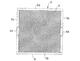
図1において、1は所要材料、例えば鉄、ステンレス、アルミ合金その他適宜の硬質材料で形成した金属コイル線巻付枠体である。2は巾約0.5mm〜0.6mm、厚み約0.05〜0.06mmくらいの扁平金属線をカールの直径が約4mmくらいのコイル状に形成した平角金属コイル線(別称、平角カール線という)であって、これを前記金属コイル線巻付枠体1に多重に巻付けて内部に多数の油分捕捉用空間部3aを有する所要厚からなる多層状平角金属コイル線フイルター3を形成してなるものである。4,4は前記多層状平角金属コイル線フイルター3の表裏面を挟持するよう設けた小メッシュの金属製ネットである。5は前記金属製ネット4,4および前記多層状平角金属コイル線フイルター3の周面を囲繞した金属製止縁体であって、図1示のように、断面略コ字形の上、下枠体5a,5bおよび、左、右枠体5c,5dに分解、組立可能に形成されている。6a,6bは把手、7は止着ビス、8は前記下枠体5bの折曲角部に所要数設けられた油排出孔である。
【0007】
9は、前記小メッシュの金属製ネット4,4の一方の外表面側に金属製ネット抑え用杆11を介在して重合配設されたパンチングメタル板であって、前記小メッシュの金属製ネット4の補強および前記小メッシュの金属製ネット4と前記パンチングメタル板9との間に空間を形成することによって、油の排出をより一層容易とするものである。10はエクスパンドメタルであって、前記パンチングメタル板9に代えて他方の小メッシュの金属製ネット4の外表面側に重合配設されてなるものである。なお前記金属製ネット抑え用杆11は、板状体、棒状体を含むものである。
【0008】
本発明は、以上説明したように、図3示の状態において、多層状平角金属コイル線フイルター3の表面から矢印方向に進入する油分を含んだ空気は、前記多層状平角金属コイル線フイルター3の裏面側へ抜ける間に前記多層状平角金属コイル線2によって形成される多数の油分捕捉用空間部3e内に油分の大部分を捕捉されて裏面へ抜けるものであり、また捕捉された油分は底部側の金属製止縁体5に形成した油排出孔8から図示しない回収カップへと回収され外部へ取出されるものである。
【0009】
また、この場合前記多層状平角金属コイル線フイルター3の表裏面を挟持する金属製ネット4,4は小メッシュからなるので、他物との接触による衝撃で、前記多層状平角金属コイル線フイルター3を構成する平角金属コイル線2が前記金属製ネットの4,4の網目部分から外部に突出して他物を傷付けたりすることもないばかりでなく、前記金属製ネット4,4はその表面側をさらにパンチングメタル板9あるいはエクスパンドメタル10により被覆されているので補強および油の排出を容易に行うことができる。
【0010】
【発明の効果】
本発明によれば、油分を捕捉するフイルター部分が金属コイル線を多重に巻付けて形成した所要厚からなる多層状金属コイル線フイルターであるため、従来の金属繊維不織布層とエクスパンドメタル層を全面圧着して板状積層体となしたものに比してフィルター内における油分捕捉用空間部が量的にきわめて多く、油分を充分に捕捉することができるとともに、前記多層状金属コイル線は金属コイル線巻付枠体に多重に巻付けられているので、コイル状部が相互にからみ合って動きがなく、安定性があり、油分の吸着力が良く、また機械的強度も大で、耐熱・耐寒性、耐久性に優れるばかりでなく、分解、組立が容易であるため、フイルター部分の清掃が容易であり、かつまた構造が簡単で安価に提供することができることは勿論のこと、特に金属製ネットを小メッシュとするとともに前記一方の小メッシュの金属製ネットの外表面側に、金属製ネット抑え用杆を介在してパンチングメタル板を重合配設したことにより、前記小メッシュの金属製ネットと前記パンチングメタル板との対面側に充分な空間を形成せしめ、油の排出をより一層容易とすることができるとともに前記金属製ネット抑え用杆が補強材となり、グリスフイルター全体の強度をより一層高めることができ、また、多層状平角金属コイル線フイルターを構成する平角金属コイル線が他物との接触による衝撃で、前記金属製ネットの網目部分から外部に突出して人体または他物を傷付けたりするのを防止することができるとともに、グリスフイルターの体裁も良くすることができる効果がある。
【0011】
また、本発明によれば、小メッシュの金属製ネットの一方の外表面側にパンチングメタル板を重合配設するとともに他方の小メッシュの金属製ネットの外表面側にエクスパンドメタルを重合配設したことにより、グリスフイルターの強度を低下することなく、コストの軽減を計ることができるばかりでなく、使用条件により、グリスフイルターの表、裏面を選択的に変えて使用することができる効果がある。
【図面の簡単な説明】
【図1】本発明の分解斜視図である。
【図2】本発明の組立正面図である。
【図3】本発明の拡大縦断面図である。
【図4】本発明の一部拡大縦断面図である。
【図5】本発明の背面側をエクスパンドメタルとした組立背面図である。
【図6】本発明のパンチングメタル板の裏面側に、金属製ネット抑え用杆を設けた一例を示す正面図である。
【符号の説明】
1 金属コイル線巻付枠体
2 平角金属コイル線
3 多層状平角金属コイル線フイルター
3a 油分捕捉用空間部
4,4 小メッシュの金属製ネット
5 金属製止縁体
5a 上枠体
5b 下枠体
5c 左枠体
5d 右枠体
6a、6b 把手
7 止着ビス
8 油排出孔
9,9 パンチングメタル板
10 エクスパンドメタル
11 金属製ネット抑え用杆[0001]
BACKGROUND OF THE INVENTION
The present invention relates to a kitchen grease filter suitable mainly for use in commercial kitchens and the like.
[0002]
[Prior art]
Conventionally, as this type of kitchen grease filter, there are, for example, Japanese Utility Model Laid-Open Nos. 63-16818, 63-218227, 5-293318, and 8-187410. . The one disclosed in Japanese Utility Model Laid-Open No. 63-16818 is a filter made by putting a thin and long curled metal into a casing formed of a metal mesh and a metal frame. No. 63-218227 discloses that an ex-band metal is laminated on both sides of a metal fiber non-woven fabric and pressed or roll-bonded as necessary, and the periphery thereof is press-sealed with aluminum fibers and aluminum expanded metal. The filter material, and the one disclosed in JP-A-5-293318 is a plate-like laminate comprising a metal fiber nonwoven fabric layer and one or two layers of an extended metal layer. The metal fiber non-woven fabric layer and the extended metal layer are pressure-bonded over the entire surface or the periphery of the plate-like laminate is sealed, and the surface of the plate-like laminate It is obtained without a kitchen filter material to form a film of fluorine-based or silicone-based resin. Furthermore, what is disclosed in Japanese Patent Application Laid-Open No. 8-187410 is a metal coil wire winding frame made of a required material, having a width of about 0.5 to 0.6 mm and a thickness of about 0.05 to 0.06 mm. A flat metal coil wire filter is formed by wrapping a flat metal coil wire formed by winding a flat metal wire into a coil shape having a curl diameter of about 4 mm and the front and back surfaces of the multilayer flat metal coil wire filter. Is made of a metal made up of a lower frame body, a left frame, and a right frame, with a substantially U-shaped cross-section capable of disassembling and assembling peripheral surfaces of the metal net and the multilayer metal coil wire filter. The left and right frame bodies are surrounded by a stop edge, and a handle is provided in the left and right frame bodies, and a required number of oil discharge holes are provided in bent corners of the lower frame body.
[0003]
[Problems to be solved by the invention]
However, in the above prior art, what is disclosed in Japanese Utility Model Laid-Open No. 63-16818 is simply a thin and long and curled metal housed in a casing formed of a metal mesh and a metal frame. As a result, the stability of the metal curl housed in the housing is poor, so the oil adsorbing power is unstable, the mechanical strength is weak, and the heat / cold resistance and durability are poor. In addition, all of those disclosed in JP-A-63-218227 and JP-A-5-293318 are formed by pressing a metal fiber nonwoven fabric layer and an expanded metal layer over the entire surface. Since it consists of a laminated body, there was a problem that the oil capturing space in the metal fiber nonwoven fabric layer is quantitatively reduced, and therefore the oil adsorption efficiency is lowered. Furthermore, what is disclosed in Japanese Patent Application Laid-Open No. 8-187410 is the oil trapping in the filter as compared with the conventional laminated plate formed by pressing the entire surface of the metal fiber nonwoven fabric layer and the expanded metal layer. The space for use is extremely large in quantity and can sufficiently capture oil, and the multi-layered flat metal coil wire is wound around the metal coil wire winding frame so that the coil-shaped portion is Since they are entangled with each other, there is no movement, they are stable, they have good oil absorption, they have high mechanical strength, they are not only excellent in heat / cold resistance and durability, but also are easy to disassemble and assemble, Although the filter portion is easy to clean and has various advantages such as simple structure and low cost supply, the front and back surfaces of the multilayer flat metal coil wire filter are simply made of gold. Because it is only sandwiched by one net made of metal, it is weak in strength, so the rectangular metal coil wire constituting the multilayered rectangular metal coil wire filter is affected by the impact caused by contact with other objects during use. In addition to the risk of damaging the human body or other objects by protruding from the mesh portion of the metal net, there are problems such as poor appearance.
[0004]
[Means for Solving the Problems]
The present invention aims to solve the above-mentioned problems, and a metal coil wire winding frame made of a required material has a flat metal with a thickness of about 0.5 to 0.6 mm and a thickness of about 0.05 to 0.06 mm. A flat rectangular metal coil wire filter is formed by wrapping a flat rectangular metal coil wire formed in a coil shape with a curl diameter of about 4 mm, and the front and back surfaces of the multilayer rectangular metal coil wire filter are made of metal. A metal stopper comprising an upper frame, a lower frame, and a left frame and a right frame, which are sandwiched between nets and can be disassembled and assembled to the peripheral surfaces of the metal net and the multilayer metal coil wire filter. In the grease filter for kitchens, in which the left and right frames are provided with handles and the required number of oil discharge holes are provided at the bent corners of the lower frame, the metal net is a small mesh metal. Net With eggplant, further the outer surface side of the metal net of the small mesh, a punching metal plate polymerized distribution and set by interposing a rod for restraining the metal net, also on the outer surface side of the metal net of the other small mesh Instead of the punching metal plate, an expanded metal is arranged in a superposed manner.
[0005]
DETAILED DESCRIPTION OF THE INVENTION
Embodiments of a grease filter for kitchen according to the present invention will be described below with reference to the drawings. 1 to 6 show an embodiment of the present invention. FIG. 1 is an exploded perspective view of a filter, FIG. 2 is a front view of the same assembly, FIG. 3 is an enlarged longitudinal sectional view, and FIG. Enlarged cross-sectional view, Fig. 5 is a rear view of the same assembly with the back side expanded metal, and Fig. 6 is a metal plate for holding the metal net on the back side of the punch metal plate (the side facing the metal net on the small mesh metal) It is a front view which shows an example which provided.
[0006]
In FIG. 1, reference numeral 1 denotes a metal coil wire winding frame formed of a required material, for example, iron, stainless steel, aluminum alloy or other appropriate hard material. 2 is a flat metal coil wire (also known as a flat curled wire) in which a flat metal wire having a width of about 0.5 mm to 0.6 mm and a thickness of about 0.05 to 0.06 mm is formed into a coil shape with a curl diameter of about 4 mm. And a multi-layered flat metal coil wire filter 3 having a required thickness and having a large number of oil trapping spaces 3a inside is formed by wrapping the metal coil wire winding frame 1 in multiple layers. It will be.
[0007]
9 is a punching metal plate that is superposed on one outer surface side of the small
[0008]
As described above, according to the present invention, in the state shown in FIG. 3, the air containing oil that enters in the direction of the arrow from the surface of the multilayer flat metal coil wire filter 3 During the escape to the back surface side, most of the oil content is captured in the numerous oil content capturing spaces 3e formed by the multilayer flat
[0009]
Further, in this case, the
[0010]
【The invention's effect】
According to the present invention, since the filter portion for capturing oil is a multilayer metal coil wire filter having a required thickness formed by wrapping a metal coil wire in multiple layers, the conventional metal fiber nonwoven fabric layer and the expanded metal layer are formed over the entire surface. Compared to the pressure-bonded plate laminate, the oil trapping space in the filter is very large in quantity and can sufficiently capture the oil, and the multilayer metal coil wire is a metal coil. Since it is wound around the wire-wound frame in multiple layers, the coiled parts are entangled with each other, do not move, have stability, have good oil adsorbing power, and have high mechanical strength. In addition to being excellent in cold resistance and durability, it is easy to disassemble and assemble, so that the filter part can be easily cleaned, and the structure is simple and can be provided at low cost. A metal net on the outer surface side of the metal net of the one of the small mesh with a small mesh by polymerized arranged a punching metal plate by interposing a rod for restraining the metal net, metal of said small mesh A sufficient space is formed on the facing side of the metal net and the punching metal plate, oil can be discharged more easily, and the metal net restraining gutter serves as a reinforcing material, increasing the strength of the entire grease filter. Further , the flat metal coil wire constituting the multilayer flat metal coil wire filter protrudes from the mesh portion of the metal net to the outside due to an impact caused by contact with the other object, thereby In addition to being able to prevent damage, it is possible to improve the appearance of the grease filter.
[0011]
Further, according to the present invention, the punching metal plate is superposed on one outer surface side of the small mesh metal net, and the expanded metal is superposed on the outer surface side of the other small mesh metal net. As a result, not only can the cost be reduced without reducing the strength of the grease filter, but also the front and back surfaces of the grease filter can be selectively changed depending on the use conditions .
[Brief description of the drawings]
FIG. 1 is an exploded perspective view of the present invention.
FIG. 2 is an assembly front view of the present invention.
FIG. 3 is an enlarged longitudinal sectional view of the present invention.
FIG. 4 is a partially enlarged longitudinal sectional view of the present invention.
FIG. 5 is an assembled rear view in which the back side of the present invention is an expanded metal.
FIG. 6 is a front view showing an example in which a metal net restraining bar is provided on the back side of the punching metal plate of the present invention.
[Explanation of symbols]
DESCRIPTION OF SYMBOLS 1 Frame with metal coil wire winding 2 Flat metal coil wire 3 Multi-layer flat metal coil wire filter 3a
Claims (1)
Priority Applications (1)
| Application Number | Priority Date | Filing Date | Title |
|---|---|---|---|
| JP2002071024A JP4072616B2 (en) | 2002-02-08 | 2002-02-08 | Kitchen grease filter |
Applications Claiming Priority (1)
| Application Number | Priority Date | Filing Date | Title |
|---|---|---|---|
| JP2002071024A JP4072616B2 (en) | 2002-02-08 | 2002-02-08 | Kitchen grease filter |
Publications (3)
| Publication Number | Publication Date |
|---|---|
| JP2003240298A JP2003240298A (en) | 2003-08-27 |
| JP2003240298A5 JP2003240298A5 (en) | 2005-08-18 |
| JP4072616B2 true JP4072616B2 (en) | 2008-04-09 |
Family
ID=27785047
Family Applications (1)
| Application Number | Title | Priority Date | Filing Date |
|---|---|---|---|
| JP2002071024A Expired - Fee Related JP4072616B2 (en) | 2002-02-08 | 2002-02-08 | Kitchen grease filter |
Country Status (1)
| Country | Link |
|---|---|
| JP (1) | JP4072616B2 (en) |
Families Citing this family (3)
| Publication number | Priority date | Publication date | Assignee | Title |
|---|---|---|---|---|
| KR100695873B1 (en) | 2005-02-18 | 2007-03-19 | 어코드 주식회사 | Apparatus for filtering for exhaust hood |
| CN110397974B (en) * | 2019-07-16 | 2021-04-16 | 林庆森 | Secondary injection range hood |
| CN114832532A (en) * | 2022-06-06 | 2022-08-02 | 苏州艾斯特环境科技有限公司 | Reinforced oil stain removal filter |
-
2002
- 2002-02-08 JP JP2002071024A patent/JP4072616B2/en not_active Expired - Fee Related
Also Published As
| Publication number | Publication date |
|---|---|
| JP2003240298A (en) | 2003-08-27 |
Similar Documents
| Publication | Publication Date | Title |
|---|---|---|
| JP4072616B2 (en) | Kitchen grease filter | |
| JP3087911U (en) | Grease filter for kitchen | |
| JP2984813B2 (en) | Grease filter for kitchen | |
| US8221567B2 (en) | Filter media and system and method of manufacturing the same | |
| JP3568935B2 (en) | Air filter | |
| JP3824595B2 (en) | Sound insulation wall panel | |
| JP4796334B2 (en) | Tick capture mat | |
| JP2006148612A5 (en) | ||
| JP2769238B2 (en) | Air purification filter | |
| US20080196369A1 (en) | Vehicle engine air intake filter | |
| JP2002143623A (en) | Composite filter for range hood | |
| JP3663466B2 (en) | Filter unit | |
| JP3119366U (en) | Insect trap | |
| JP2595333Y2 (en) | Wind noise prevention microphone | |
| US7578408B1 (en) | Patterned frame structure | |
| JP2647957B2 (en) | Air filter | |
| JP3008437U (en) | Spring mattress | |
| JPS63150015U (en) | ||
| JPH02129233U (en) | ||
| JPH11320725A (en) | Honeycomb body | |
| JPH04110054A (en) | Air purifier | |
| JP3277250B2 (en) | Range hood filter | |
| KR200189521Y1 (en) | Mattress | |
| TWI331879B (en) | ||
| JP2007132079A5 (en) |
Legal Events
| Date | Code | Title | Description |
|---|---|---|---|
| A521 | Written amendment |
Free format text: JAPANESE INTERMEDIATE CODE: A523 Effective date: 20050207 |
|
| A621 | Written request for application examination |
Free format text: JAPANESE INTERMEDIATE CODE: A621 Effective date: 20050207 |
|
| A977 | Report on retrieval |
Free format text: JAPANESE INTERMEDIATE CODE: A971007 Effective date: 20070221 |
|
| A131 | Notification of reasons for refusal |
Free format text: JAPANESE INTERMEDIATE CODE: A131 Effective date: 20070320 |
|
| A521 | Written amendment |
Free format text: JAPANESE INTERMEDIATE CODE: A523 Effective date: 20070611 |
|
| TRDD | Decision of grant or rejection written | ||
| A01 | Written decision to grant a patent or to grant a registration (utility model) |
Free format text: JAPANESE INTERMEDIATE CODE: A01 Effective date: 20071113 |
|
| RD04 | Notification of resignation of power of attorney |
Free format text: JAPANESE INTERMEDIATE CODE: A7424 Effective date: 20071116 |
|
| R155 | Notification before disposition of declining of application |
Free format text: JAPANESE INTERMEDIATE CODE: R155 |
|
| A61 | First payment of annual fees (during grant procedure) |
Free format text: JAPANESE INTERMEDIATE CODE: A61 Effective date: 20071227 |
|
| FPAY | Renewal fee payment (event date is renewal date of database) |
Free format text: PAYMENT UNTIL: 20110201 Year of fee payment: 3 |
|
| R150 | Certificate of patent or registration of utility model |
Free format text: JAPANESE INTERMEDIATE CODE: R150 |
|
| LAPS | Cancellation because of no payment of annual fees |